GE MDS DS-MERCURY900 Mercury 900 Wireless Transceiver User Manual Book1
GE MDS LLC Mercury 900 Wireless Transceiver Book1
GE MDS >
Contents
manual pt 2
MDS 05-4446A01, Rev. A MDS Mercury User’s Guide 87
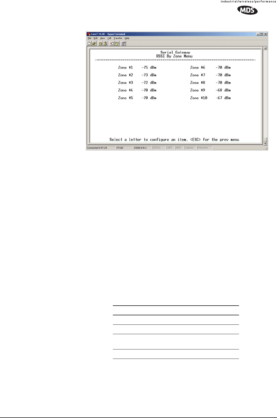
Figure 3-44. RSSI by Zone Menu
TIP: Under normal circumstances, the signal levels in each zone should
be within a few decibels of each other. If you see one that is signif-
icantly lower or higher, it may be a sign of radio frequency inter-
ference from another signal source on the 900 MHz band.
See “Network Performance Notes” on Page 96 for further infor-
mation.
Event Log Menu
The transceiver’s microprocessor monitors many operational parame-
ters and logs them. Events are classified into four levels of importance,
which are described in Table 3-5. Some of these events will result from
a condition that prevents the normal of the unit—these are “critical”
events. These will cause the unit to enter an “alarmed” state and the PWR
LED to blink until the condition is corrected. All events are stored in the
Event Log that can hold up to 8,000 entries.
Time and Date The events stored in the Event Log are time-stamped using the time and
date of the locally connected device. Remote units obtain this informa-
tion from the Access Point when they associate with it. The Access Point
obtains the time and date from a Time Server. This server can generally
be provided by a standard Windows PC server SNTP application. In the
absence of the SNTP services, the user must manually enter it at the
Table 3-5. Event Classifications
Level Description/Impact
Informational Normal operating activities
Minor Does not affect unit operation
Major Degraded unit performance but
still capable of operation
Critical Prevents the unit from operating
88 MDS Mercury User’s Guide MDS 05-4446A01, Rev. A
Access Point. (See “Device Information” on Page 42 for SNTP server
identification.) The manually set time and date clock is dependent on the
unit’s primary power. A loss of power will reset the clock to January 1,
2002 but will not affect previously stored error events.
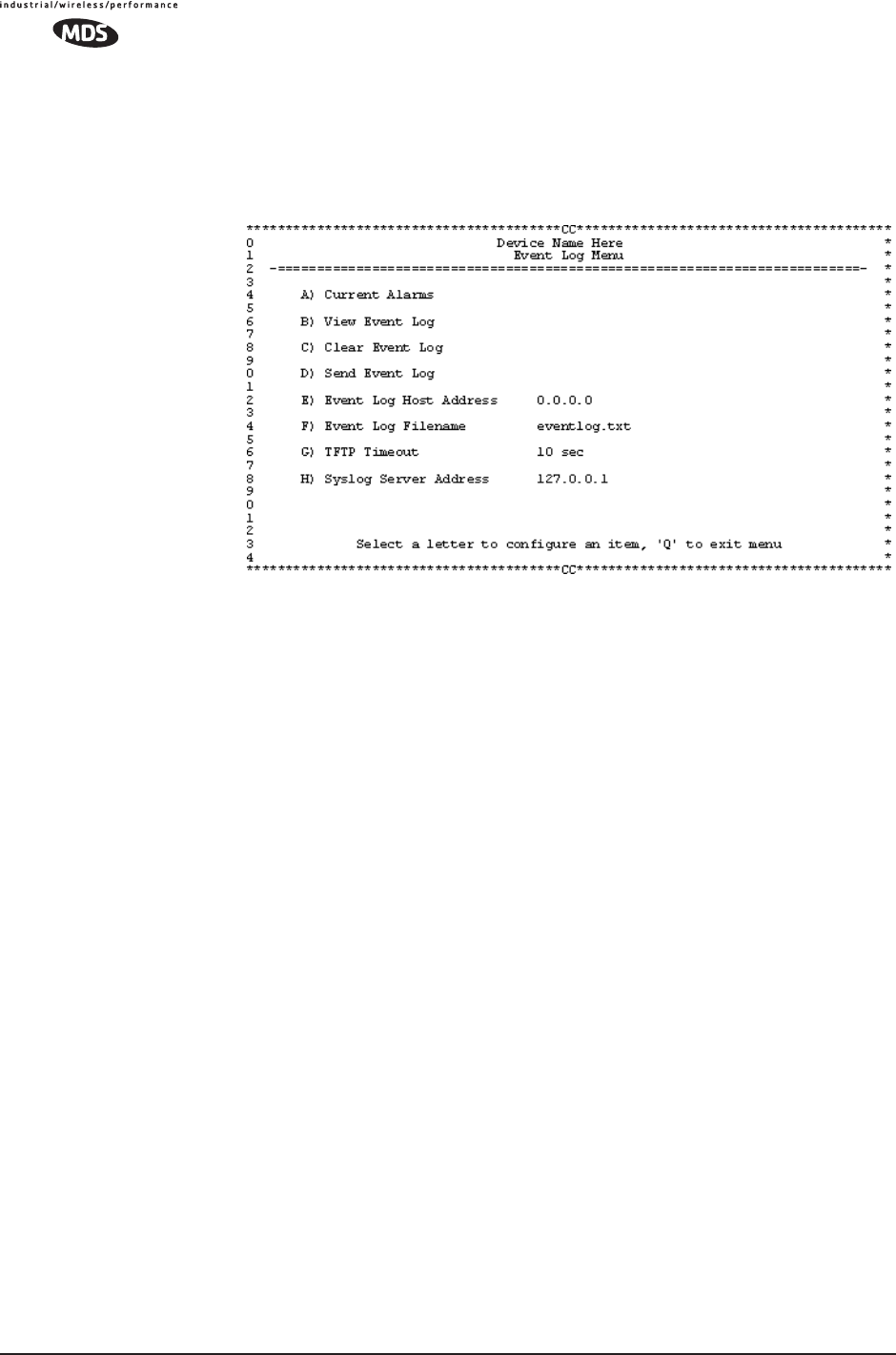
Figure 3-45. Event Log Menu
•Current Alarms (Telnet/Terminal only)—View list of root causes that
have placed the Device Status in the alarmed state. (See “Alarm
Conditions” on Page 128)
•View Log—View a list of events stored in the current log. Some
of these events are stored in volatile memory and will be erased
with a loss of power. The events are numbered for easier iden-
tification and navigation.
•Clear Log—Purges the log of all events
TIP: Save your Event Log before choosing to clear it in order
to retain potentially valuable troubleshooting information.
(See “Upgrading the Firmware” on Page 102 for an over-
view on how to transfer files from the transceiver to a com-
puter on the network using TFTP.)
•Send Log (Telnet/Terminal only)—Initiate TFTP transfer of the
unit’s event Event Log in a plain text (ASCII) file to a TFTP
server at the remote location.
•TFTP Host Address (Telnet/Terminal only)—IP address of the com-
puter on which the TFTP server resides. This same IP address is
used in other screens/functions (reprogramming, logging, etc.).
Changing it here also changes it for other screens/functions.
[Any valid IP address; 127.0.0.1]
MDS 05-4446A01, Rev. A MDS Mercury User’s Guide 89
•Filename (Telnet/Terminal only)—Name to be given to the Event
Log file sent to the TFTP server for archiving.
[Any 40-char alphanumeric string; Blank]
NOTE: You may want to change the filename to reflect the type
of log you intend to archive and/or its date.
•TFTP Time-out (Telnet/Terminal only)—Time in seconds the TFTP
server will wait for a packet ACK (acknowledgment) from the
transceiver before suspending the file transfer.
[10 to 120 seconds; 10]
•Syslog Server—IP address to which alarms are sent using the sys-
log message format. [Any valid IP address; 0.0.0.0]
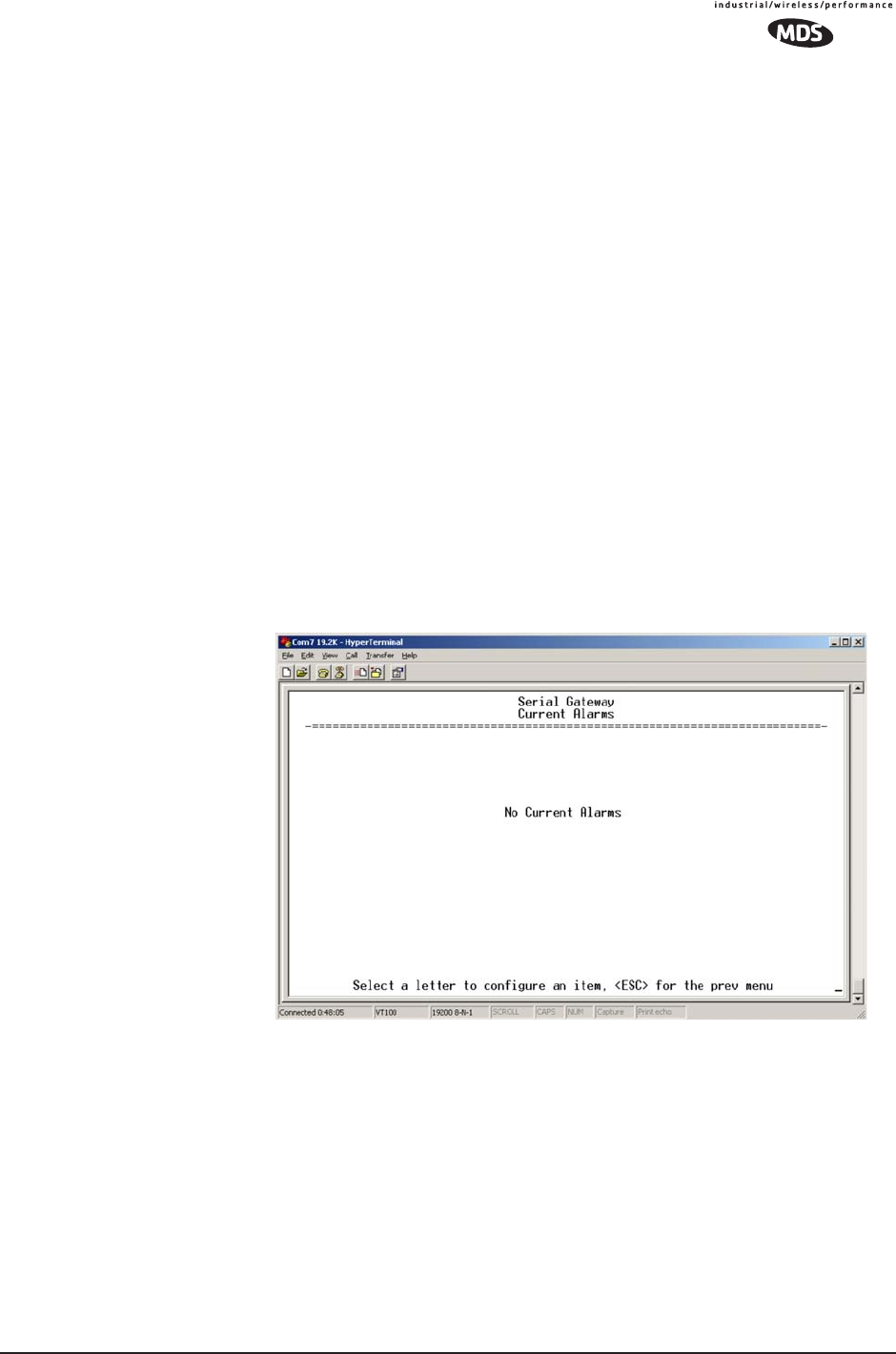
View Current Alarms Most events, classified as “critical” will make the PWR LED blink, and
will inhibit normal operation of the transceiver. The LED will remain
blinking until the corrective action has been completed.
An alarm condition is different from a log event in the sense that an
alarm is persistent in nature. That is, an alarm condition remains as an
alarm until it has been cleared by correcting the cause (see Table 4-6 on
Page 130 for corrective action).
Figure 3-46. Current Alarms Screen
90 MDS Mercury User’s Guide MDS 05-4446A01, Rev. A
View Event Log See Table 4-4 on Page 128 for event classifications.
Figure 3-47. Sample Event Log Screen
Packet Statistics Menu
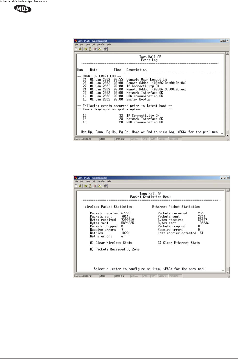
Figure 3-48. Sample Packet Statistics Menu
Wireless Packet
Statistics •Packets received—Over-the-air data packets received by this unit
•Packets sent—Over-the-air data packets sent by this Remote.
•Bytes received—Over-the-air data bytes received by this Remote.
•Bytes sent—Over-the-air data bytes sent by this Remote.
•Packets dropped—To-be-transmitted packets dropped as a result
of a lack of buffers in the RF outbound queue.
•Receive errors—Packets that do not pass CRC. This may be due
to transmissions corrupted by RF interference.
MDS 05-4446A01, Rev. A MDS Mercury User’s Guide 91
•Retries—Number of requests to re-send a data packet before it is
acknowledged. If the packet was not acknowledged, this
counter is not incremented.
•Retry errors—Packets discarded after exceeding seven retries
over-the-air.
•Clear Wireless stats—Resets the statistics counter.
Ethernet Packet
Statistics •Packets received—Packets received by the transceiver through
the Ethernet port.
•Packets sent—Packets transmitted by the transceiver through the
Ethernet port.
•Bytes received—Data bytes received by this Remote through its
LAN port.
•Bytes sent—Data bytes sent by this Remote.
•Packets dropped—Received packets dropped as a result of a lack
of buffers.
•Receive errors—Packets that do not pass CRC. This may be due
to collisions in the Ethernet LAN.
•Lost carrier detected—A count of the number of packets that the
unit attempted to send out the Ethernet port when the carrier sig-
nal of the Ethernet was not present. (No carrier present could be
due to a loose connection, bad or wrong cable, or equipment
failure at the other end of the Ethernet cable.)
•Clear Ethernet stats—Resets the statistics counter.
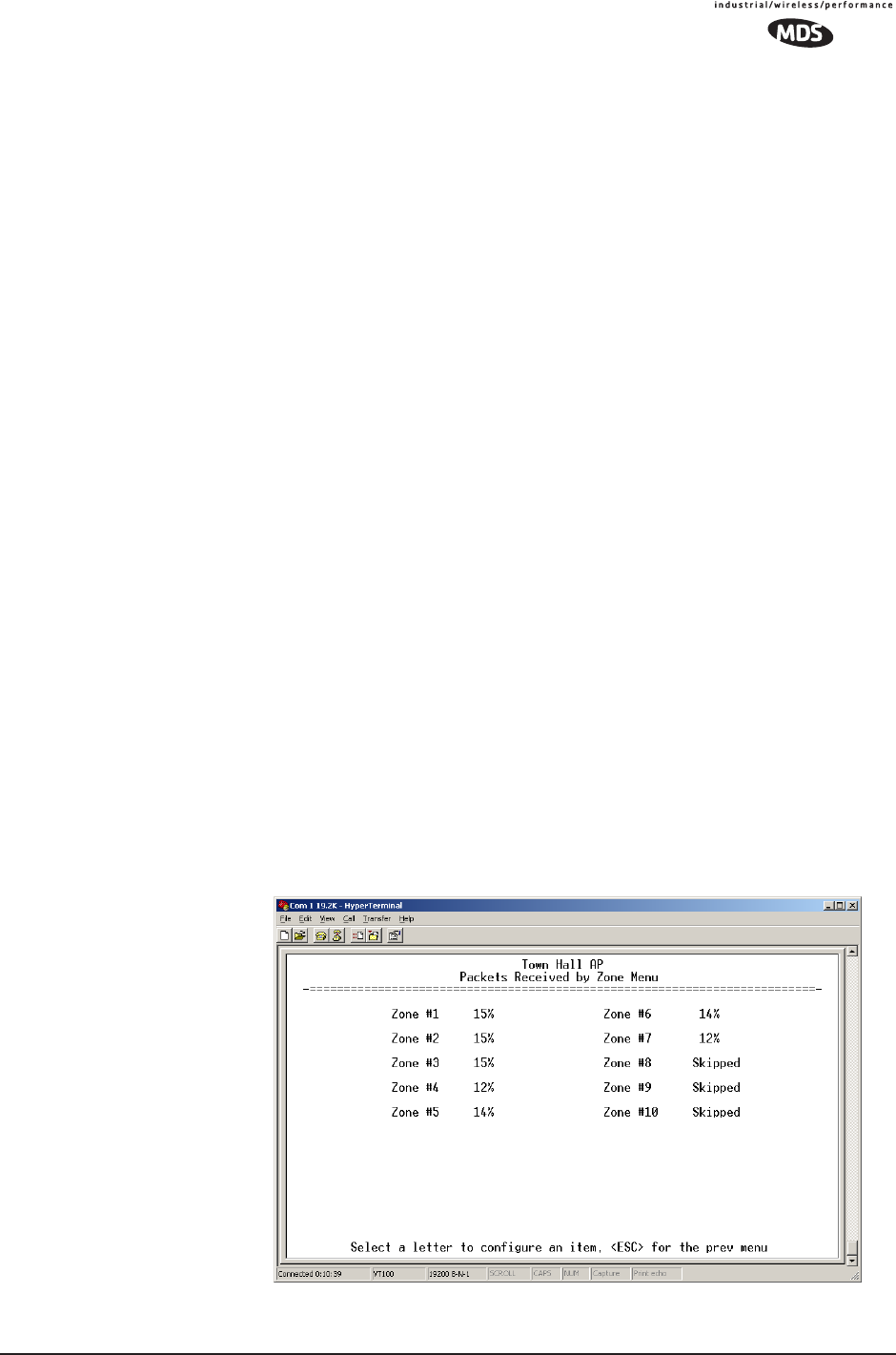
Packets Received by
Zone This screen, shown in Figure 3-49, presents a breakdown of wireless
packet statistics by-zone. All zones should report similar numbers. If
one or more zones report lower numbers than the others (2% reduction),
the specific zone is probably experiencing interference. An improve-
ment can be realized by blocking this zone (see Main Menu>>Radio Config-
uration>>Skip Zone Option).
Invisible place holder
Figure 3-49. Packets Received By Zone Menu
92 MDS Mercury User’s Guide MDS 05-4446A01, Rev. A
Wireless Network Status
(Remotes Only)
The Wireless Network Status screen provides information on a key
operating process of the transceiver—the association of the Remote with
the Access Point. The following is a description of how this process
takes place and as monitored on the Figure 3-50. Wireless Network
Status Screen" on page 92.
The Transceiver’s
Association Process After the Remote is powered up and finishes its boot cycle, it begins
scanning the 900 MHz band for beacon signals being sent out from AP
units. If the Remote sees a beacon with a Network Name that is the same
as its own, the Remote will stop its scanning and temporarily synchro-
nize its frequency-hopping pattern to match the one encoded on the AP’s
beacon signal. The Remote waits for three identical beacon signals from
the AP and then it toggles into a fully synchronized “associated” state.
If the Remote does not receive three identical beacons from the Access
Point unit within a predetermined time period, it returns to a scanning
mode and continues to search for an AP with a matching network name
in its beacon.
Under normal circumstances, the association process should be com-
pleted within 20 seconds after boot-up. This time can vary depending on
the beacon period setting at the AP. See Beacon Period description in Sec-
tion 3.5.1, Radio Configuration Menu (beginning on Page 52).
Remote units are always monitoring the beacon signal. If an associated
Remote loses the AP’s beacon for more than 20 seconds, the association
process starts again.
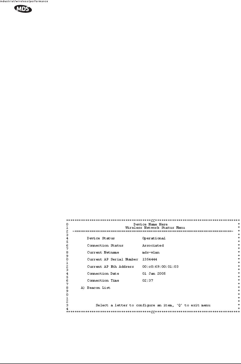
The Wireless
Network
Status Screen
(Remote only)
Figure 3-50. Wireless Network Status Screen
•Connection Status—Current state of the wireless network com-
munication.
•Scanning—The unit is looking for an Access Point beacon
signal.
MDS 05-4446A01, Rev. A MDS Mercury User’s Guide 93
•Exp(ecting) Sync(hronization)—The unit has found a valid
beacon signal for its network.
•Hop Sync—The unit has changed its frequency hopping pat-
tern to match that of the Access Point.
•Connected —The unit has established a radio (RF) connec-
tion with the Access Point, but has not obtained cyber-secu-
rity clearance to pass data.
•Associated —This unit has successfully synchronized and
associated with an Access Point. This is the normal status.
•Alarmed—The unit is has detected one or more alarms that
have not been cleared.
•Current AP Mac Address—Wireless address of Access Point with
which the Remote is associated.
•Current AP IP Address—IP address of Access Point with which
the Remote is associated.
•Association Date—Date of last successful association with an
Access Point.
•Association Time—Time of day association was established on
the association date.
•Latest AP Firmware Version—
•AP Auto Upgrade—
•AP Reboot when Upgraded—
Remote Listing Menu (Access Points Only)
Figure 3-51. Remote Listing Menu
(List of transceivers associated with this AP)
•MAC Address—Hardware address of the Remote transceiver.
•IP Address—IP Address of the Remote transceiver.
•State—Current association state of the Remote transceiver.
•AgeTime—Time, in minutes, remaining before the device (address)
94 MDS Mercury User’s Guide MDS 05-4446A01, Rev. A
will be deleted from the table.
Each transceiver maintains a table with the addresses of the devices
it communicates with. The age-time countdown is restarted to 5
minutes every time a message to/from that device is detected. If no
traffic is exchanged with that device, it then “ages out” of the table.
When traffic is detected it is included again in the table. This opti-
mizes memory space utilization.
•DataRate—Supported data rate by this unit.
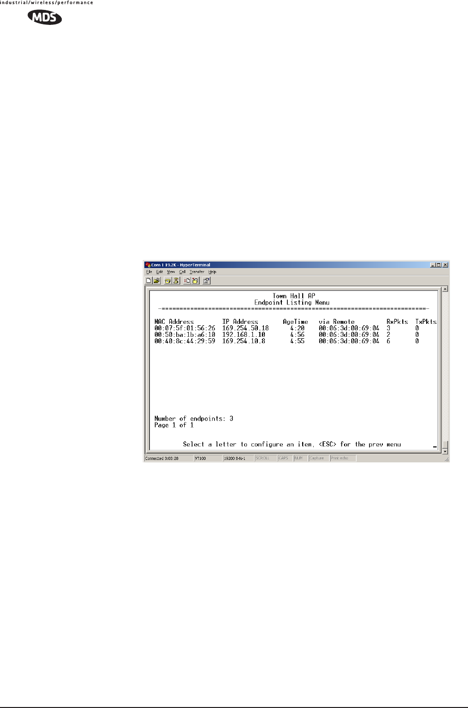
Endpoint Listing Menu
(Access Points Only)
This list shows all of the non-Mercury 900 Ethernet devices that are
known to the transceiver and is equivalent to the ARP table of IP
devices.
Figure 3-52. Endpoint Listing Menu
(Lists all equipment attached to REMOTE transceivers in the network)
•MAC Address—Hardware address of endpoint device.
•IP Address—IP Address of endpoint device.
•AgeTime—Time, in minutes, remaining before the device (address)
will be deleted from the table.
Each AP maintains a table with the addresses of the remote radios it
communicates with. The age-time countdown is restarted to 5 min-
utes every time a message to/from that remote is detected. If no traf-
fic is exchanged with that remote, it then “ages out” of the table.
When traffic is detected it is included again in the table. This opti-
mizes memory space utilization.
•via Remote—Hardware address of the radio connected to this device.
•RxPkts—Over-the-air data packets received by the transceiver. and
MDS 05-4446A01, Rev. A MDS Mercury User’s Guide 95
passed on to the endpoint device.
•TxPkt—Number of packets received from the endpoint device and
passed over-the-air.
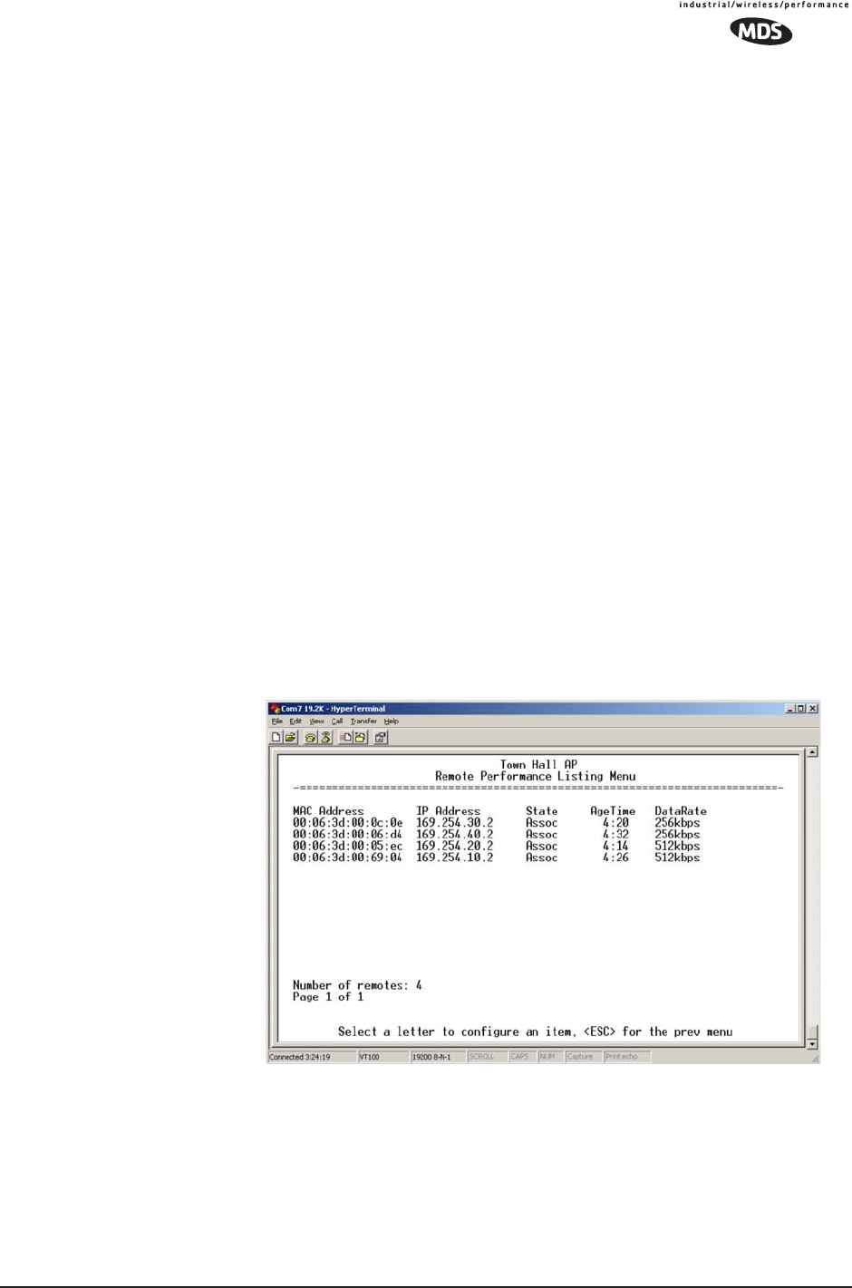
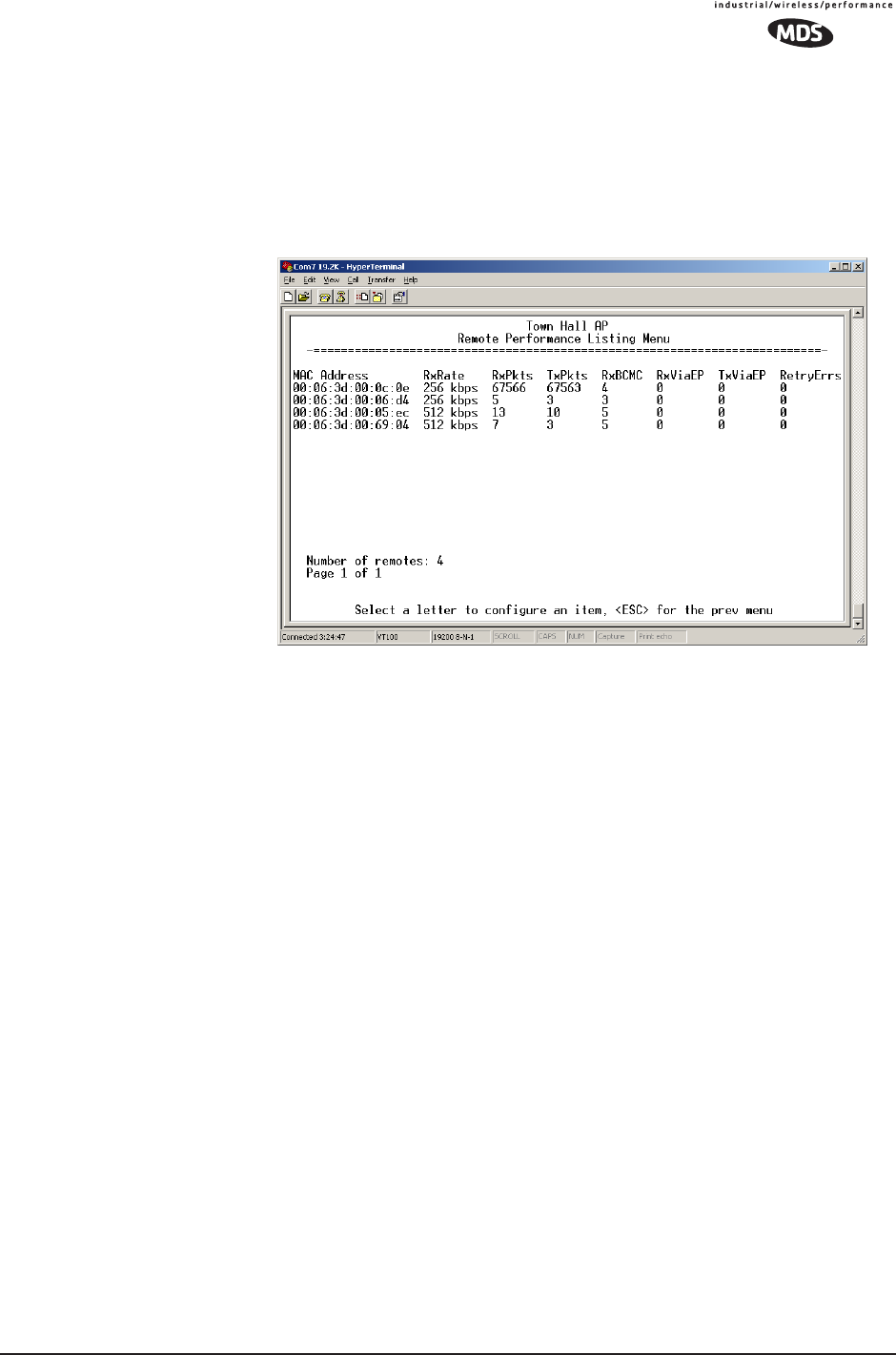
Remote Performance Listing Menu
(Access Points Only)
Figure 3-53. Remote Performance Listing Menu for AP
This screen provides a unit-by-unit summary of all Remote units cur-
rently associated with this Access Point. The parameters are displayed
in a column format with each line corresponding to one Remote.
•RxRate—Over-the-air data rate the radio is currently using. All
transceivers do not need to use the same rate.
•RxPkts—Over-the-air data packets received from this unit.
•TxPkts—Over-the-air data packets sent to this unit.
•RxBCMC—Total number of Broadcast and/or Multicast packets
received over-the-air.
•RxViaEP—Packets received by the transceiver through the Ether-
net port.
•TxViaEP—Packets sent by the transceiver through the Ethernet
port.
•RetryEr—Packets discarded after exceeding five retries
over-the-air.
96 MDS Mercury User’s Guide MDS 05-4446A01, Rev. A
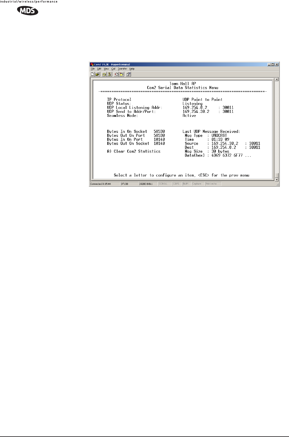
Serial Data Statistics Menu
This screen provides a summary of port activity for both serial data
ports. These values will be reset to zero after a reboot cycle.
Figure 3-54. Serial Data Statistics Screen
•Bytes in on port—Number of bytes received by the transceiver
through the serial interface
•Bytes out on port—Number of bytes transmitted by the trans-
ceiver through the serial interface
•Bytes in on socket—Number of bytes received by the trans-
ceiver through the IP socket
•Bytes out on socket—Number of bytes transmitted by the trans-
ceiver through the IP socket
In general, the number of bytes Out on Socket should follow
the number of bytes In On Port as all bytes received on the
serial port should be transmitted out to the IP interface. The
same should be true in the opposite direction, bytes Out On
Port should follow bytes In On Socket.
•Clear Com1 Statistics—Resets counter to zero.
3.8.2 Network Performance Notes
Principles of Network Operation
The following is a list of points that are useful for dealing with the net-
working aspects of the transceiver.
1. The transceiver acts as a bridge.

MDS 05-4446A01, Rev. A MDS Mercury User’s Guide 97
•If any radio in your network is connected to a large LAN, such
as may be found in a large office complex, there may be undes-
ired multicast/broadcast traffic over the air. As a bridge, the
radios transmit this type of frame.
• The radio goes through a listening and learning period at
start-up before it will send any packets over either of its ports.
This is about 10 seconds after the CPU’s operating system has
finished its boot cycle.
•The bridge code in the transceiver operates and makes decisions
about packet forwarding just like any other bridge. The bridge
code builds a list of source MAC addresses that it has seen on
each of its ports.
There are a few general rules that are followed when a packet is
received on any port:
•If the destination address is a multicast or broadcast address,
forward the packet to all remotes.
•If the destination address is not known, forward the packet to
all remotes.
•If the destination address is known, forward the packet to the
port that the destination is known to be on (usually the RF
port).
• The bridge code uses Spanning Tree Protocol (STP) to pre-
vent loops from being created when connecting bridges in
parallel. For example, connecting two remotes to the same
wired LAN could create a loop if STP was not used. Every
bridge running STP sends out Bridge Protocol Data Units
(BPDUs) at regular intervals so that the spanning tree can be
built and maintained. BPDUs are 60-byte multicast Ethernet
frames.
2. Distance affects throughput. Because of timers and other compo-
nents of the protocol, there is a maximum distance limit of 40 miles
for reliable operation. After this, although data still flows, the
throughput will start to drop and latency will increase, due to addi-
tional retries between the radios. Repeater stations may be used to
extend this range.
3. Throughput calculations must take into account all overhead.
The following is an example of the overhead at each layer for a
100-bytes of data over UDP:
• Data: 100 bytes
• UDP header: 8 bytes
• IP header: 20 bytes
• Ethernet header: 14 bytes
• 802.11 header 24 bytes
• LLC and SNAP header: 8 bytes
• MDS PHY header and FCS: 16 bytes

98 MDS Mercury User’s Guide MDS 05-4446A01, Rev. A
Total over-the-air frame size=190 bytes
If the frame is directed (for example: not multicast/broadcast), the
802.11 ACK frame must be accounted for:
• 14 bytes—802.11 ACK
• 30 bytes—Over-the-air ACK frame (including 16 MDS PHY
bytes)
If the 802.11 encapsulated Ethernet frame (NOT the UDP or Ethernet
frame) exceeds the RTS threshold, then the overhead for RTS/CTS
frames must also be accounted for.
• 20 bytes—802.11 RTS.
• 14 bytes—802.11 CTS.
• 66 bytes—Total Over-the-air bytes for RTS/CTS with MDS
PHY headers.
If the frame is TCP, then there is a 32-byte TCP header instead of the
8-byte UDP header.
•ARP requests, ARP replies and BPDU’s will affect throughput.
• ARP requests are 60-byte Ethernet frames. 142 bytes
over-the-air.
• ARP replies are 60-byte Ethernet frames. 142 bytes
over-the-air.
• BPDUs are 60-byte Ethernet frames. 142 bytes over-the-air.
Note that the overhead to put a single Ethernet frame
over-the-air is 82 bytes. If RTS/CTS is invoked, it is 148 bytes.
Therefore, the overhead for a minimal Ethernet frame
(60 bytes) is 128% and, as such, gives the transceiver a poor
small-packet performance.
4. Station-to-Station traffic reduces throughput
•When sending frames from an endpoint connected to one trans-
ceiver to another endpoint with a different transceiver, the
throughput will be halved at best. This is because all frames
must go through the AP and thus are transmitted twice over the
same radio system. Therefore, in the previous 100-byte UDP
example, the number of over-the-air bytes will be 380 bytes
(190 bytes x 2) if the frame has to go station-to-station.
5. Interference has a direct correlation to throughput.
• Interference could be caused by any unnecessary traffic on the
network from unrelated activities, or Radio Frequency Interfer-
ence in the wireless spectrum.

MDS 05-4446A01, Rev. A MDS Mercury User’s Guide 99
Tips for Optimizing Network Performance
Here are some suggestion on things to try that may maximize
throughput:
1. AP Only: Increment the Dwell Time to the maximum of 262.1 ms.
This lowers the overhead since it will stay longer on a channel. The
down side is that if a particular channel is interfered with it will take
longer to hop to another channel.
(Main Menu>>Radio Configuration>>Dwell Time)
2. AP Only: Change the Beacon Period to Normal (508 ms). This will
also reduce the overhead of beacons sent out. On the down side,
association time may be a little longer.
(Main Menu>>Radio Configuration>>Beacon Period)
3. Change the Fragmentation Threshold to the maximum of 1600. Longer
packets will be sent over the air reducing overhead. On the other
hand, if a packet is corrupted it will take longer to be retransmitted.
(Main Menu>>Radio Configuration>>Fragmentation Threshold)
4. Increase the RTS Threshold to 1600. RTS mechanism is used to
reserve a time slot if packets exceed this number. On the other hand,
a hidden-node might interfere more often than if RTS was not used.
(Main Menu>>Radio Configuration>>RTS Threshold)
Decreasing the RTS Threshold, to the 100 to 200 range, may improve
throughput on a busy network. It will add small packets, but reduce
collisions (and resulting re-tries) of large packets.
(Main Menu>>Radio Configuration>>RTS Threshold)
5. Activate compression on the Radio Configuration Menu (Compres-
sion enabled).
6. Use the Performance Information Menu to check the packets received by
zone. (Remotes Only: Main Menu>>Performance Information>>Packet
Statistics>>Packets Received by Zone)
Readings should be close in value. A significantly lower value (2%
reduction) probably indicates interference. Performance can be
improved by blocking the affected zones at the Access Point. (Main
Menu>>Radio Configuration>>Skip Zone Option)
7. Use the Performance Information Menu to check for errors, retries and
dropped packets. Do the same with Ethernet traffic.
With weak signals, interference, or hidden nodes, the optimal per-
formance may be lower due to collisions and retries.

100 MDS Mercury User’s Guide MDS 05-4446A01, Rev. A
Data Latency—TCP versus UDP Mode
The latency of data passing through a network will depend on user data
message length, the overall level of traffic on the network, and the
quality of the radio path.
Under ideal conditions—low traffic and good RF signal path—the
latency for units operating in the TCP mode, will typically be around 5
ms in each direction. However, when UDP multicast traffic is trans-
ported, the outbound packet latency (from AP to remote) is dependent
on the beacon period.
UDP multicast packet latency can be minimized by setting the Beacon
Period to Fast (52 ms). Changing beacon rate to Fast will result in an
average latency of 31 ms, assuming outbound packets wait for a beacon
transmission 50% of the time (26ms) plus the normal packet latency
(5 ms).
Data Compression
Enabling this option uses an LZO compression algorithm for
over-the-air data. Varying levels of data reduction are achieved
depending on the nature of the data. Text files are typically the most
compressible, whereas binary files are the least compressible. On
average, a 30% increase in throughput can be achieved with compres-
sion enabled.
Compression is used on data packets of 100 bytes or more, including
Ethernet, IP, and TCP/UDP headers.
Packets-per-Second (PPS)
The radio has a limit of 70 PPS. Consider this restriction when planning
your network, especially when smaller packets are expected to make up
the majority of the traffic as is the case with VoIP (Voice over IP).
3.9 MAINTENANCE
In the course of operating a wireless network, you will likely want to
take advantage of product improvements, and to read and archive the
configuration of your individual transceivers using the Maintenance
Menu. This section provides detail information on how to take advan-
tage of these services.
The maintenance tasks for the transceiver are:
•Reprogramming— Managing and selecting the unit’s operating
system firmware resources. (See “Reprogramming Menu” on
Page 101)
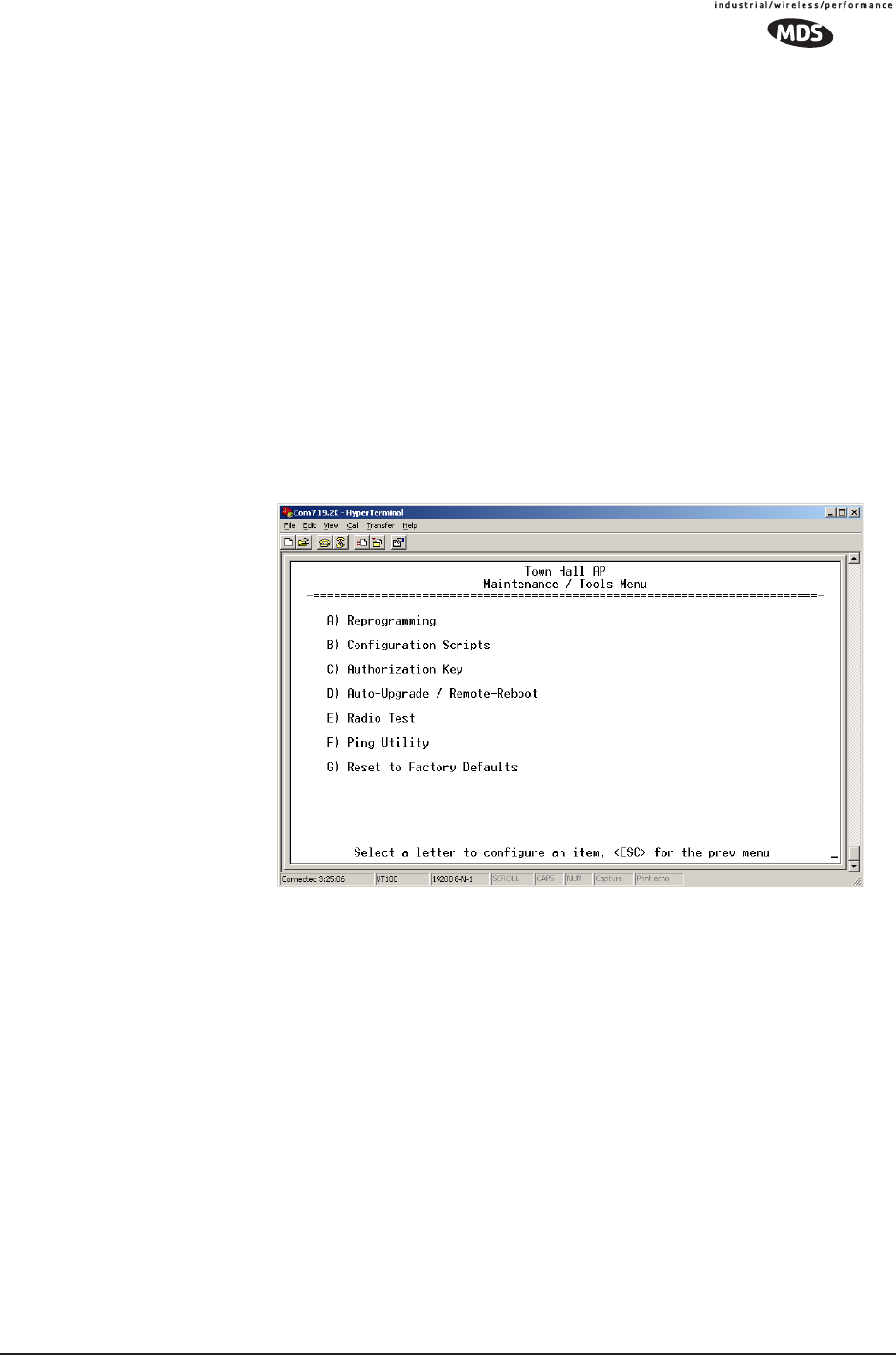
MDS 05-4446A01, Rev. A MDS Mercury User’s Guide 101
•Configuration Scripts—Saving and importing data files contain-
ing unit operating parameters/settings. (See “Configuration
Scripts Menu” on Page 106)
•Authorization Key—Alter the unit’s overall capabilities by
enabling the built-in resources. (See “Authorization Keys Menu”
on Page 114)
•Auto-Upgrade/Remote-Reboot—Configure when remotes retrieve
new firmware versions from the associated AP, and whether or
not they reboot to the new firmware after receiving the new
firmware. (See “Auto-Upgrade/Remote-Reboot Menu” on
Page 115)
•Radio Test—A diagnostic tool for testing RF operation.
(See “Radio Test Menu” on Page 116)
•Ping Utility—Diagnostic tool to test network connectivity.
(See “Ping Utility Menu” on Page 117)
Figure 3-55. Maintenance Menu
3.9.1 Reprogramming Menu
The transceiver has two copies of the firmware (microprocessor code)
used for the operating system and applications. One copy is “active” and
the second one is standing by, ready to be used. You can load new firm-
ware into the inactive position and place it in service whenever you
desire.
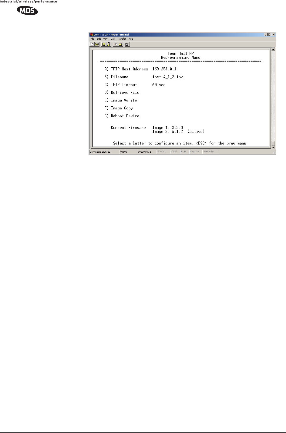
102 MDS Mercury User’s Guide MDS 05-4446A01, Rev. A
Figure 3-56. Reprogramming Menu
(Shown with “Image Copy” Selected)
•TFTP Host Address—IP address of the host computer from which
to get the file. [Any valid IP address] This same IP address is used
in other screens/functions (reprogramming, logging, etc.).
Changing it here also changes it for other screens/functions.
•Filename—Name of file to be received by the TFTP server.
[Any 40-character alphanumeric string] Verify that this corresponds
to the TFTP directory location. May require sub-directory, for
example: \firmware\mercury\mercury-4_4_0.ipk.
•TFTP Timeout—Time in seconds the TFTP server will wait for a
packet ACK (acknowledgment) from the transceiver before
suspending the file transfer. [2 to 60 seconds; 10]
•Retrieve File—Initiate the file transfer from the file from TFTP
server. Placed into inactive firmware position in the trans-
ceiver’s non-volatile memory [Y, N]
•Image Verify—Initiate the verification of the integrity of firmware
file held in unit.
•Image Copy—Initiate the copying of the active firmware into the
inactive image.
•Reboot Device—Initiate rebooting the transceiver. This will
interrupt data traffic through this unit, and the network if per-
formed on an Access Point. Intended to be used to toggle
between firmware images.
NOTE: See “Upgrading the Firmware” on Page 102 for details
on setting up the TFTP server.
Upgrading the Firmware
From time-to-time MDS offers upgrades to the transceiver firmware.
One version of the firmware provides core software resources for all

MDS 05-4446A01, Rev. A MDS Mercury User’s Guide 103
transceiver models. Loading new firmware into the unit will not alter
any privileges provided by Authorization Keys and does not require the
transceiver be taken off-line until you want to operate the unit from the
newly installed firmware image.
You must use the embedded Management System for all firmware activ-
ities, including uploading from a TFTP server.
File transfers can be initiated through any of the three Management
System gateways:
•Terminal-Emulator—Use a terminal emulator program on your
PC, such as HyperTerminal, connected directly to the trans-
ceiver’s COM1 port via a serial cable.
•Telnet—Text-based access to the Management System through
a network connection.
•Web Browser—Connect to the transceiver using a Web browser
on a local PC connected directly to the radio’s LAN port or
associated network.
Firmware images are provided free-of-charge on the MDS Web site at:
www.microwavedata.com/service/technical/support
Installing New
Firmware by TFTP To install firmware by TFTP, you will need:
•A PC with a TFTP server running.
• The IP address of the PC running the TFTP server.
If you do not know your computer’s address on a Windows PC, you can
use the RUN function from the Start menu and enter winipcfg or ipconfig to
determine your local PC’s IP address. The IP address of the radio can be
found under the Management Systems’ Configuration menu.
(See “Network Configuration Menu” on Page 44.)
A TFTP server is available on the MDS Web site at:
www.microwavedata.com/service/technical/support/downloads.asp
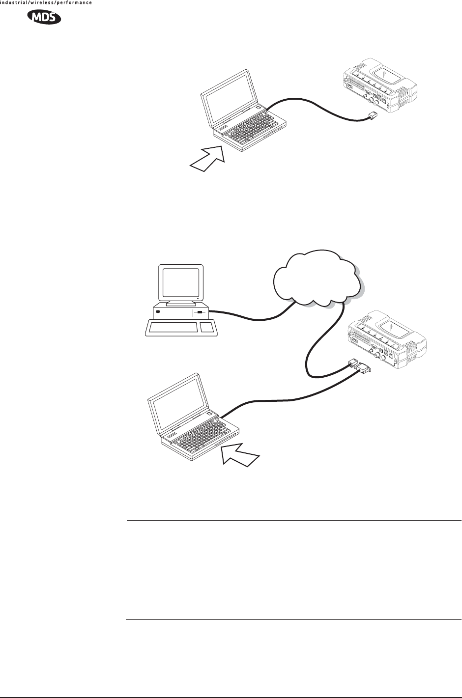
There are several alternatives to connecting the transceiver for firmware
upgrade. Figure 3-57 and Figure 3-58 show two variations. It is essen-
tial all of the equipment be on the same subnet.
104 MDS Mercury User’s Guide MDS 05-4446A01, Rev. A
Invisible place holder
Figure 3-57. Firmware Upgrade Setup—Option 1
(TFTP Server and Firmware File on Same CPU)
Invisible place holder
Figure 3-58. Firmware Upgrade Setup—Option 2
(TFTP Server and Firmware File on Remote Server)
NOTE: The LAN and COM1 ports share a common data channel when
loading firmware over-the-air. Transferring the radio firmware
image file (≈ 3 Mb), may take several minutes depending on
traffic between the TFTP server and the transceiver.
Regardless of your connection to the transceiver, loading firm-
ware/configuration files into the unit’s flash-RAM is much
slower than loading software onto a PC hard drive or RAM.
Upgrade Procedure To load a new firmware file (filename.ipk) into the transceiver, use the
following procedure:
LAN
PORT
LOCAL WINDOWS PC
WITH CONFIG. FILES
IP ADDRESS: 172.0.0.A
IP ADDRESS: 172.0.0.B
TFTP
SERVER
& TELNET
TRANSCEIVER
C
R
O
S
S
-
O
V
E
R
C
A
B
L
E
INITIATE UPLOAD
FROM HERE
AP or REMOTE
IP ADDRESS: 172.0.0.B
TFTP
SERVER ETHERNET
PORT
COM1
PORT
(DCE)
INITIATE UPLOAD
FROM HERE
REMOTE PC
W/FIRMWARE FILES
HUB/LAN/WAN/MAN
TCP/IP
LAN
PORT
COM1, 2, ETC.
(DTE)
IP ADDRESS: w.x.y.z
LOCAL WINDOWS PC
IP ADDRESS: 172.0.0.A
TERMINAL
PROGRAM
9
-
PINS
E
R
I
A
L
C
A
B
L
E

MDS 05-4446A01, Rev. A MDS Mercury User’s Guide 105
1. Launch a TFTP server on a PC connected either directly or via a
LAN to the Ethernet port (LAN) of the radio. Point the server
towards the directory containing the firmware image file.
2. Connect to the Management System by whichever means is conve-
nient: Browser or Telnet via the LAN, or Terminal emulator via the
COM1 port.
3. Go to the MS Reprogramming Menu.
(Main Menu>>Maintenance Menu>>Reprogramming Menu)
4. Fill in the information for the:
•TFTP Host Address—IP Address of server (host computer) run-
ning TFTP server.
•Retrieve File—Name of file (filename.ipk) to be pulled from the
TFTP server holding the firmware file.
5. Pull the firmware file through the TFTP server into the transceiver.
(Main Menu>>Maintenance Menu>>Reprogramming Menu>>Retrieve File)
Status messages on the transfer are posted on the Management Sys-
tem screen.
NOTE: The new firmware image file that replaces the “Inactive
Image” file will be automatically verified.
6. Reboot the transceiver.
Main Menu>>Maintenance Menu>>Reprogramming Menu>>Reboot Device
NOTE: When upgrading to firmware 6.0.0 or later, the unit creates
internal files following the first reboot. This one-time process
delays the response of the HTTP interface for 5-10 minutes. If
DC power is cycled (turned off and back on) during this
process, the files will have to be created again. It is recom-
mended that you wait until this 5-10 minute process is
complete before verifying operation of HTTP, HTTPS, or
SSH.
7. Test the transceiver for normal operation.
End of Procedure
106 MDS Mercury User’s Guide MDS 05-4446A01, Rev. A
Error Messages During File Transfers
It is possible to encounter errors during a file transfer. In most cases
errors can be quickly corrected by referring to Table 3-6.
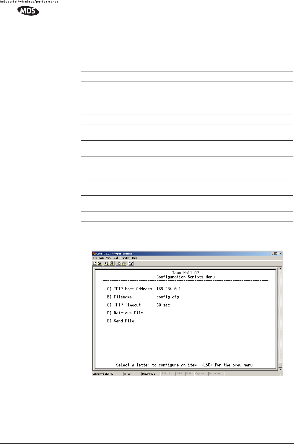
3.9.2 Configuration Scripts Menu
Figure 3-59. Configuration Files Menu
•TFTP Host Address—IP address of the computer on which the
TFTP server resides. [Any valid IP address]
Table 3-6. Common Errors During TFTP Transfer
Error Message Likely Cause/Corrective Action
Invalid File Type Indicates that the file is not a valid firmware
file. Locate proper file and re-load.
File not found Invalid or non-existent filename on TFTP
server
Invalid file path Invalid or non-existent file path to TFTP server
Timeout TFTP transfer time expired. Increase the
timeout value.
Flash Error Flash memory error. Contact factory for
assistance.
Bad CRC Cyclic Redundancy Check reporting a
corrupted file. Attempt to re-load, or use a
different file.
Version String Mismatch Invalid file detected. Attempt to re-load, or use
a different file.
Sending LCP Requests The PPP server is querying for any clients that
may need to connect.
Port not Enabled The serial port is disabled.

MDS 05-4446A01, Rev. A MDS Mercury User’s Guide 107
•Filename—Name of file containing this unit’s configuration pro-
file that will be transferred to the TFTP server. The configura-
tion information will be in a plain-text ASCII format.
[Any 40-character alphanumeric string] May require sub-directory,
for example: config\mercury-config.txt. (See “Using Configura-
tion Scripts” on Page 107)
NOTE: The filename field is used in identifying the desired
incoming file and as the name of file being exported to the TFTP
server. Before exporting the unit’s configuration, you may want
to name it something that reflect the unit’s services or identifi-
cation.
•TFTP Timeout—Time in seconds the TFTP server will wait for a
packet ACK (acknowledgment) from the transceiver before
suspending the file transfer. [10 to 120 seconds; 10]
•Retrieve File—Initiate the file transfer of the configuration file
from TFTP server into the transceiver.
•Send File—Initiate the file transfer from the transceiver’s current
configuration file to TFTP server.
NOTE: See Upgrading the Firmware on Page 102 for details on
setting up the TFTP server.
A Brief Description of Configuration Files
If you plan to have more than a few radios in your network, use the con-
figuration file feature to configure similar units from a common set of
parameters. There are over 50 user-controllable settings that can be used
to optimize the network and saved into a Configuration File. However,
only four essential parameters need to be reviewed and altered to use the
file with another transceiver.
A Configuration File (data file) will make it easy to apply your unique
settings to any radio(s) you wish. Configuration files will also provide
you with a tool to restore parameters to a “known good” set, in the event
that a parameter is improperly set and performance is affected.
(See “Using Configuration Scripts” on Page 107 for detailed instruc-
tions and a sample configuration file.)
Using Configuration Scripts
Configuration Scripts can be created and downloaded from the trans-
ceiver that contain a wealth of information on the unit. This file can
serve many purposes, not the least of which is to keep a permanent
“snapshot” of the unit’s configuration at a point in time. These files can
also be used to view the setup of a unit without needing to connect to it.
Examining archival files can be a useful source of information during
troubleshooting.
In the next few sections you will learn about the contents of the file and,
how to use it as a template for configuring multiple transceivers with the

108 MDS Mercury User’s Guide MDS 05-4446A01, Rev. A
same profile. Ultimately, standardized files can be uploaded into the
transceiver to speed up the installation process.
Configuration Files can also be uploaded into a transceiver to restore the
settings of a unit using a previously-saved configuration of the unit. This
is particularly convenient after finishing a test using some experimental
settings.
Sample of an Exported Configuration File
The following is a sample of a typical configuration file as produced by
a transceiver containing over 150 parameters; many of which are user
editable. The presentation has been slightly altered to allow notes to
appear below associated parameter lines. Some of the values used in the
calibration of the unit’s built-in test equipment have been deleted to
reduce space. This presentation is offered as a guide to the type of infor-
mation contained in the file. See “Editing Configuration Files” on
Page 113 for further information.
NOTE: The parameter names and the data values from the Exported
Configuration File are shown in bolded text. Any description
will be found below in an indented paragraph. Descriptions for
parameters that are functionally identical to both COM1 are
not repeated.
Beginning of Configuration File
; MDS mercury
; Created 00-03-2002 6:59:41
IP Address: 192.168.1.1
The IPv4 address of this unit. This field is unnecessary if DHCP is
enabled.
NOTE: Changing the IP value via the network will cause a loss of
communication with other devices unaware of the new
address.
IP Netmask: 255.255.255.0
The IPv4 local subnet mask. This field is unnecessary if DHCP is
enabled.
IP Gateway: 0.0.0.0
The IPv4 address of the network gateway device, typically a router.
This field is unnecessary if DHCP is enabled.
Ethernet Address: 00:06:3D:00:00:5D
The physical Ethernet MAC (Media Access Controller) address of
the device. This value is set by the factory and cannot be changed.
Wireless Address: 00:06:3D:00:00:5C
The physical wireless MAC (Media Access Controller) address of

MDS 05-4446A01, Rev. A MDS Mercury User’s Guide 109
the device. This value is set by the factory and cannot be changed.
Model Number: 900
The model number of this unit. This value is set by the factory and
cannot be changed.
Serial Number: 1026295
The serial number of this unit. This value is set by the factory and
cannot be changed.
Unit Name: Library Admin Office
A name for this unit. It appears at the top of every menu screen.
Owner: Hilltop College IT
The name of the owner of this unit.
Contact: IT Dept. X232
The contact person regarding this unit.
Description: Link to Campus Server
A brief general description of this unit.
Location: Hollister Bldg. RM450
The location of this unit.
Com1 Port Config: 8N1
Configuration of character size, type of parity, and number of stop
bits to be used.
Max Remotes Allowed: 50
The maximum number of remotes allowed to connect to this Access
Point.
Device Mode: Access Point
Configures the unit to act as a Remote or an Access Point. The
Access Point option is not allowed unless the unit is specifically
ordered as such, or an Authorization Key has been purchased to
allow it.
Dwell Time: 32.8
The amount of time the unit spends at any given frequency in its
hopping pattern. This field is only changeable by an Access Point.
Remotes read the Masters value upon association.
Hop Pattern: 1
RSSH Calibration: 235
RSSL Calibration: 190
Freq Calibration: 8402
Network Name: West Campus Net
The name of the network this unit belongs to. The unit will only
communicate with devices having identical Network Names.
Date Format: Generic

110 MDS Mercury User’s Guide MDS 05-4446A01, Rev. A
Specifies the format of the date.
• Generic = dd Mmm yyyy
• European = dd-mm-yyyy
• US = mm-dd-yyyy
Console Baud: 19200
The baud rate of the serial menu console. Default value is
19200 bps.
Company Name: MDS
Version Name: 06-1234567
Product Name: mercury
Beacon Period: Normal
The amount of time in milliseconds between beacon transmissions
by the AP.
Data Rate: 512 kbps
The selected over-the-air data rate. A lower data rate generally
allows more distance between the unit and its Access Point.
RF Output Power Setpoint: 30
The desired amount of RF output power, measured in dBm.
Power Cal Table DAC1: 98
21 additional values follow; do not alter
Active Boot Image: 0
Tx Coefficient1: 0
31 additional values follow; do not alter
Rx Coefficient1: 0
14 additional values follow; do not alter
Skipped Hop Zone1: Active
Skipped Hop Zone2: Skip
Skipped Hop Zone3: Active
Skipped Hop Zone4: Active
Skipped Hop Zone5: Active
Skipped Hop Zone6: Active
Skipped Hop Zone7: Active
Skipped Hop Zone8: Active
Skipped Hop Zone9: Active
Skipped Hop Zone10: Active
Firmware TFTP Host IP: 63.249.227.105
Address of the TFTP Host from which firmware images are down-
loaded
Firmware TFTP Filename: mercury-4_4_0.ipk
Eventlog TFTP Host IP: 192.168.1.3

MDS 05-4446A01, Rev. A MDS Mercury User’s Guide 111
Address of TFTP Host to which to send the event log
Eventlog TFTP Filename:
Config Script TFTP Host IP: 192.168.1.33
Address of TFTP Host to which to send the event log
Config Script TFTP Filename: mercury_config.txt
Fragmentation Threshold: 1600
Maximum packet size allowed before fragmentation occurs
RTS Threshold: 500
Number of bytes for the RTS/CTS handshake boundary
RSSI Threshold: 0
RSSI value at that the connection is deemed “degraded”
SNR Threshold: 0
SNR value at that the connection is deemed “degraded”
SNMP Read Community: public
Community string for read access using SNMPv1
SNMP Write Community: private
Community string for write access using SNMPv1
SNMP Trap Community: public
Community string sent with traps using SNMPv1
SNMP Trap Manager #1: 0.0.0.0
IP Address of a SNMP manager to which traps will be sent
SNMP Trap Manager #2: 0.0.0.0
SNMP Trap Manager #3: 0.0.0.0
SNMP Trap Manager #4: 0.0.0.0
SNMP Trap Manager #5: 0.0.0.0
Auth trap enable: disabled
Setting to enable SNMP authentication traps
Trap Version: v1 Traps
Selects which SNMP trap format
Package 1 Version: 1.1.0
Indicates the version of firmware in Image 1
Package 2 Version: 1.1.0
TFTP Timeout: 20
Com1 Serial Data Enable: disabled
Setting to enable COM1 data mode
Com1 Serial Data Mode: UDP
IP Protocol for COM1 data mode

112 MDS Mercury User’s Guide MDS 05-4446A01, Rev. A
Com1 Serial Data Baud Rate: 9600
Baud rate for COM1 data mode
Com1 Serial Data Tx IP Address: 0.0.0.0
COM1 data will be sent to this IP address
Com1 Serial Data Tx IP Port: 0
COM1 data will be sent to this IP port
Com1 Serial Data Rx IP Port: 0
COM1 data will be received on this IP port
Com1 Serial Data Rx IP Address: 0.0.0.0
COM1 data will be received on this IP address
SNTP Server IP: 0.0.0.0
The IPv4 address of NTP/SNTP Time Server
Com1 Serial Data Seamless Mode: enabled
Setting to enable seamless mode for COM1 data mode
Com1 Serial Data Delimiter Chars: 4
Minimum number of characters which will be considered a gap in
seamless mode for COM1
Com1 Serial Data Buffer Size: 20
Number of output characters which will be buffered in seamless
mode for COM1
RF Frequency Hopping Format: USA/CANADA
(Read Only) The frequency-hopping rules the radio is configured to
operate under
SNMP Enable: disabled
Enable/Disable SNMP Agent
Hop Protocol: 1
Frequency hopping protocol version
DHCP Server Enable: disabled
Enable/Disable DHCP Server Daemon
DHCP Netmask: 255.255.255.0
The IP Address to be used as the DHCP Netmask
DHCP Start Address: 192.168.0.11
The IP Address to be used as the starting address
DHCP End Address: 192.168.0.22
The IP Address to be used as the ending address
Approved Remotes List Enable: disabled
Setting to enable the Approved Remotes List

MDS 05-4446A01, Rev. A MDS Mercury User’s Guide 113
Encryption Enable: disabled
Setting to enable over-the-air data encryption
HTTP Enable: enabled
Setting to enable the HTTP interface
Telnet Enable: enabled
Setting to enable the Telnet interface
HTTP MD5 Authentication: disabled
Setting to enable MD5 Digest Authentication
Automatic Key Rotation: disabled
Setting to enable Automatic Key Rotation
Approved APs List Enable: disabled
Setting to enable the Approved Access Points List
Watch-Link-Status Flag @ AP: disabled
A flag that controls whether the Remotes care about the AP's Ether-
net Link Status
Network Name Hash Enable: disabled
A flag that controls whether MD5 hashing is applied to the network
name
End of Configuration File
Editing Configuration Files
Once a Remote unit’s operation is fine-tuned, use the Configuration
Scripts Menu on Page 106 to save a copy of the configuration in a PC.
Once the file is saved in the PC it can be used as a source to generate
modified copies adjusted to match other devices. The configuration files
can be modified using a text editor or an automated process. (Not pro-
vided by MDS).
We recommend that you review and update the following parameters for
each individual unit. Other parameters may also be changed.
Table 3-7. Common User-Alterable Parameters
Field Comment Range
IP Address Unique for each individual radio Any legal IP address
IP Gateway May change for different groups or
locations
Any legal IP address
Unit Name Should reflect a specific device.
This information will appear in
Management System headings
Any 20-character
alphanumeric string
Location Used only as reference for network
administration
Any 40-character
alphanumeric string
114 MDS Mercury User’s Guide MDS 05-4446A01, Rev. A
Each resulting file should be saved with a different name. We recom-
mend using directories and file names that reflect the location of the unit
to facilitate its identification.
Editing Rules • You may include only parameters you want to change.
• Change only the parameter values.
• Capitalization counts in some field parameters.
(Example: System Mode)
• Comment Fields
a. Edit, or delete anything on each line to the right of the
comment delineator, the semicolon (;).
b. Comments can be of any length, but must be on the same
line as the parameter, or on a new line that begins with a
semicolon character.
c. Comments after parameters in files exported from a trans-
ceiver do not need to be present in your customized files.
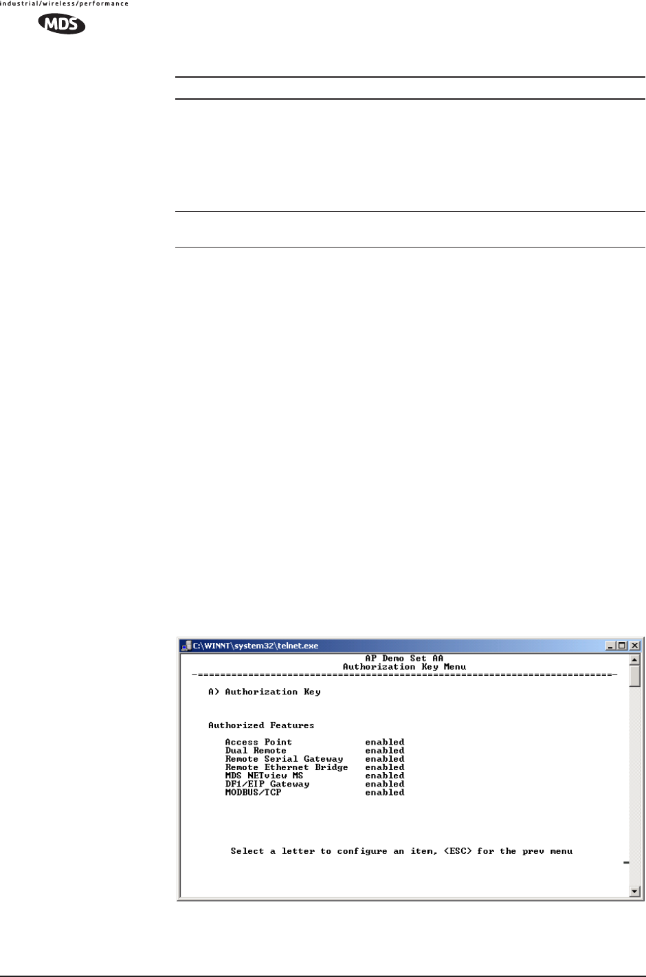
3.9.3 Authorization Keys Menu
Figure 3-60. Authorization Key Menu
System Mode The application of the parameter in
this field is dependent on the
authorized options stored in the
unit’s permanent memory.
The mode must be compatible with
any previously installed
Authorization Keys.
“Access Point”
“Dual Remote”
“Serial Remote”
“Ethernet Remote”
NOTE: These are
case-sensitive.
Network Name Used to identify different groups or
locations
Any 15-character
alphanumeric string
Table 3-7. Common User-Alterable Parameters (Continued)
Field Comment Range

MDS 05-4446A01, Rev. A MDS Mercury User’s Guide 115
•Authorization Key—Initiate the entering of an Authorization Key
into the transceiver’s non-volatile memory.
•Authorized Features—List of authorized features available for use
[enabled, disabled].
Some models will show an additional selection called Encryption
under Authorized Features.
3.9.4 Auto-Upgrade/Remote-Reboot Menu
NOTE: This menu is only available when MDS NETview MS key is
enabled.
Invisible place holder
Figure 3-61. Auto-Upgrade / Remote Reboot Menu
•Auto Upgrade—Causes all of the Remotes associated to this AP
to read the AP’s newest firmware version (active or inactive)
and upload it via TFTP to the inactive image, but only if it is
newer than the Remote’s current firmware.
•Reboot on Upgrade—Determines how a Remote will behave once
it has uploaded new firmware from the AP as part of an
auto-upgrade. When enabled, the Remote will reboot to the new
firmware.
•Force Reboot—Causes all of the Remotes associated to this AP
to reboot immediately. They will reboot to their current active
image—the same as if the power were re-cycled.
116 MDS Mercury User’s Guide MDS 05-4446A01, Rev. A
NOTE: To use the Auto Upgrade/Reboot feature, both the AP and
Remotes must already be running version 4.4.0 or newer firm-
ware.
Exception: If the AP has already been upgraded to version
4.4.0 and the Remote is still at 3.5.0 or older, you can upgrade
the Remote by using the AP as a file server. This method
allows for only one remote to be upgraded at a time. Instruc-
tions for this method are given below.
Firmware Upgrade (with AP Acting as a File Server)
An AP running firmware version 4.4.0 (or newer) may be used as a file
server to upgrade Remotes running older firmware (3.5.0 or earlier).
Follow the steps below to perform the upgrade:
1. At the Reprogramming Menu (Page 102), Enter the AP’s IP Address
in the TFTP Server field.
2. Enter upgrade_from_ap.ipk in the Filename field.
NOTE: The filename is case sensitive.
3. Perform the firmware download.
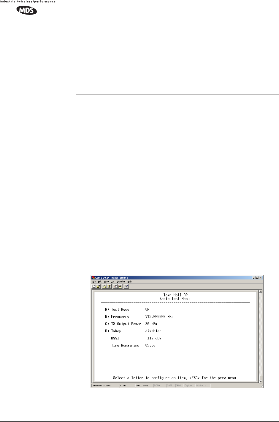
3.9.5 Radio Test Menu
This area provides several useful tools for installers and maintainers.
You can manually key the radio transmitter to make measurements of
antenna performance. (See “Antenna Aiming” on Page 135 for details.)
Figure 3-62. Radio Test Menu
Shown with Test Mode set to ON
MDS 05-4446A01, Rev. A MDS Mercury User’s Guide 117
NOTE : Use of the Test Mode will disrupt traffic through the radio. If
the unit is an Access Point, it will disrupt traffic through the
entire network.
Test Mode function is automatically limited to 10 minutes and
should only be used for brief measurement of transmit power.
It may also be manually reset to continue with the testing or
turned off.
•Test Mode—Controls access to the transceiver’s suite of tools.
[ON, OFF; OFF]
•Frequency—Set radio operating frequency during the testing
period to a single frequency. [915.0000 MHz]
•TX Output Power—Temporarily overrides the power level set-
ting in the Radio Configuration Menu. [20]
•TxKey—Manually key the radio transmitter for power mea-
surements. [Enable, Disable; Disable]
•RSSI—Incoming received signal strength on frequency
entered in the frequency parameter on this screen (–dBm).
This RSSI measurement is updated more frequently than the
RSSI by Zone display of the Performance Information menu.
3.9.6 Ping Utility Menu
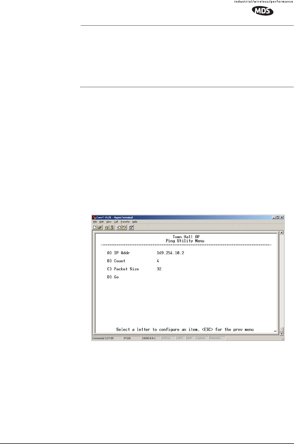
Figure 3-63. Ping Utility Menu
•IP Addr—Address to send a PING. [Any valid IP address]
•Count—Number of PING packets to be sent.
•Packet Size—Size of each PING data packet (bytes).
•Go—Send PING packets to address shown on screen.
Screen will be replaced with detailed report of PING activity.
Press any key after viewing the results to return to this menu.

118 MDS Mercury User’s Guide MDS 05-4446A01, Rev. A
3.9.7 Reset to Factory Defaults
To reset all transceiver parameters back to the factory defaults,
including the password, you must enter a special code (authorization
key) provided by the factory in place of the user name at the time of
login.
This procedure is useful when several parameters have been modified,
and there is no track of changes. It causes the transceiver to return to a
known state.
Password Reset
As part of the reset action the transceiver’s password is reverted to the
default value of admin. As a security measure, this event causes all radio
parameters to return to the factory default settings, including zone skip-
ping (as applicable), baud rate settings, network name, security phrase,
etc.

MDS 05-4446A01, Rev. A MDS Mercury User’s Guide 119

120 MDS Mercury User’s Guide MDS 05-4446A01, Rev. A

MDS 05-4446A01, Rev. A MDS Mercury User’s Guide 121
4 TROUBLESHOOTING &
RADIO MEASUREMENTS
4 Chapter Counter Reset Paragraph
Contents
4.1 TROUBLESHOOTING.............................................................123
4.1.1 Interpreting the Front Panel LEDs ............................................123
4.1.2 Troubleshooting Using the Embedded Management System ...124
4.1.3 Using Logged Operation Events ...............................................128
4.1.4 Alarm Conditions .......................................................................128
4.1.5 Correcting Alarm Conditions .....................................................130
4.1.6 Logged Events ..........................................................................131
4.2 RADIO (RF) MEASUREMENTS............................................. 133
4.2.1 Antenna System SWR and Transmitter Power Output .............134
4.2.2 Antenna Aiming .........................................................................135

122 MDS Mercury User’s Guide MDS 05-4446A01, Rev. A

MDS 05-4446A01, Rev. A MDS Mercury User’s Guide 123
4.1 TROUBLESHOOTING
Successful troubleshooting of a wireless system is not difficult, but
requires a logical approach. It is best to begin troubleshooting at the
Access Point unit, as the rest of the system depends on the Access Point
for synchronization data. If the Access Point has problems, the operation
of the entire wireless network will be affected.
When communication problems are found, it is good practice to begin
by checking the simple things. Applying basic troubleshooting tech-
niques in a logical progression can identify many problems.
Multiple
Communication
Layers
It is important to remember the operation of the network is built upon a
radio communications link. On top of that are two data levels— wireless
MAC, and the data layer. It is essential that the wireless aspect of the
Access Point and the Remotes units to be associated are operating prop-
erly before data-layer traffic will function.
Unit Configuration There are over 50 user-configurable parameters in the Management
System. Do not overlook the possibility that human error may be the
cause of the problem. With so many possible parameters to look at and
change, a parameter may be incorrectly set, and then what was changed
is forgotten.
To help avoid these problems, we recommend creating an archive of the
transceiver’s profile when your installation is complete in a Configura-
tion File. This file can be reloaded into the transceiver to restore the unit
to the factory defaults or your unique profile. For details on creating and
archiving Configuration Files, see “Using Configuration Scripts” on
Page 107.
Factory Assistance If problems cannot be resolved using the guidance provided here,
review the MDS web site’s technical support area for recent soft-
ware/firmware updates, general troubleshooting help, and service infor-
mation. Additional help is available through our Technical Support
Department. (See “TECHNICAL ASSISTANCE” on the inside of the
rear cover.)
4.1.1 Interpreting the Front Panel LEDs
An important set of troubleshooting tools are the LED status indicators
on the front panel of case. You should check them first whenever a
problem is suspected. Table 2-2 on Page 27 describes the function of
each status LED. Table 4-1 below provides suggestions for resolving

124 MDS Mercury User’s Guide MDS 05-4446A01, Rev. A
common system difficulties using the LEDs, and Table 4-2 provides
other simple techniques.
4.1.2 Troubleshooting Using the Embedded
Management System
If you have reviewed and tried the things mentioned in Table 4-1 and
still have not resolved the problem, there are some additional tools and
techniques that can be used. The embedded Management System is a
good source of information that may be used remotely to provide pre-
liminary diagnostic information, or may even provide a path to cor-
recting the problem.
Table 4-1. Troubleshooting Using LEDs—Symptom-Based
Symptom Problem/Recommended System Checks
PWR LED does not
turn on
a. Voltage too low—Check for the proper supply voltage at
the power connector. (10–30 Vdc)
b. Indefinite Problem—Cycle the power and wait
(≈ 30 seconds) for the unit to reboot. Then, recheck for
normal operation.
LINK LED does not
turn on
a. Network Name of Remote not identical to desired Access
Point—Verify that the system has a unique Network Name.
b. Not yet associated with an Access Point with the same
Network Name.
Check the “Status” of the unit’s process of associating with
the Access Point. Use the Management System.
c. Poor Antenna System—Check the antenna, feedline and
connectors. Reflected power should be less than 10% of
the forward power reading (SWR 2:1 or lower).
PWR LED is
blinking
a. Blinking indicates an alarm condition exists.
b. View Current Alarms and Event Log and correct the
problem if possible.
(See “Using Logged Operation Events” on Page 128)
c. Blinking will continue until the source of the alarm is
corrected, for example, a valid IP address is entered, etc.
LAN LED does not
turn on
a. Verify the Ethernet cable is connect at both ends.
b. Verify that the appropriate type of Ethernet cable is used:
straight-through, or crossover.
LAN LED lights, but
turns off after some
time
Verify traffic in LAN. Typically, the radio should not be placed
in high traffic enterprise LANs, as the it will not be able to pass
this level of traffic. If needed, use routers to filter traffic.

MDS 05-4446A01, Rev. A MDS Mercury User’s Guide 125
Table 4-2. Basic Troubleshooting Using the Management System
Symptom Problem/Recommended System Checks
Remote does not
associate; stays in
HOPSYNC
a. Verify the AP has sufficiently large number in the “Max
Remotes” parameter of the Network Configuration Menu.
b. Verify the correct MAC address is listed in the “Approved
Remotes List” or “Approved Access Points List” of the
Security Configuration menu.
Serial data is slow
with UDP multicast
traffic
Change Beacon Period to FAST.
(Radio Configuration Menu)
Cannot access the
MS through COM1
a. Connect to unit via Telnet or Web browser
b. Disable the serial mode for COM1
(Serial Gateway Configuration>>Com1 Serial Data
Port>>Status>>Disabled)
or, if you know the unit’s data configuration:
a. Connect to COM 1 via a terminal set to VT100 and the
port’s data baud rate.
b. Type +++
c. Change the terminal’s baud rate to match the transceiver’s
Console Baud Rate.
d. Type +++
Display on
terminal/Telnet
screen garbled
Verify the terminal/terminal emulator or Telnet application is
set to VT100
Cannot pass IP
data to WAN.
a. Verify your IP settings.
b. Use the PING command to test communication with the
transceivers in the local radio system.
c. If successful with local PING, attempt to PING an IP unit
attached to a transceiver.
d. If successful with the LAN PINGs, try connecting to a
known unit in the WAN.
Wireless Retries
too high.
Possible Radio Frequency Interference—
a. If omnidirectional antennas are used, consider changing to
directional antennas. This will often limit interference to
and from other stations.
b. Try skipping some zones where persistent interference is
known or suspected.
c. The installation of a filter in the antenna feedline may be
necessary. Consult the factory for further assistance.
Password
forgotten.
a. Connect to the transceiver using a terminal through the
COM1 Port.
b. Obtain a password-resetting Authorization Key from your
factory representative.
c. Enter the Authorization Key at the login prompt as a
password.
Packet Repeat
Mode troubles
(extra characters in
data, data not
delivered)
Verify that all radios in the network have their Packet
Redundancy Mode set to the same selection (Single Packet
vs. Packet Repeat Mode).

126 MDS Mercury User’s Guide MDS 05-4446A01, Rev. A
The following is a summary of how several screens in the Management
System can be used as diagnostic tools. For information on how to con-
nect to the Management System See “STEP 3—CONNECT PC TO THE
TRANSCEIVER” on Page 22.
Starting Information Screen
(See Starting Information Screen on Page 40)
The Management System’s “homepage” provides some valuable bits of
data. One of the most important is the “Device Status” field. This item
will tell you if the unit is showing signs of life.
If the Device Status field says “associated,” then look in the network
areas beginning with network data statistics. If it displays some other
message, such as Scanning, Hop Sync or Alarmed, you will need to
determine why it is in this state.
The Scanning state indicates a Remote unit is looking for an Access
Point beacon signal to lock onto. It should move to the Hop Sync and
finally to the Associated state within less than a minute. If this Remote
unit is not providing reliable service, look at the Event Logs for signs of
lost association with the Access Point or low signal alarms. Table 4-3
provides a description of the Device Status messages.
If the Remote is in an “Alarmed” state, the unit may still be operational
and associated. Look for the association state in the Wireless Network
Status screen to determine if the unit is associated. If it is, then look at
the Error Log for possible clues.
If the unit is in an “Alarmed” state and not able to associate with an
Access Point unit, then there may be problem with the wireless network
layer. Call in a radio technician to deal with wireless issues. Refer the
technician to the RADIO (RF) MEASUREMENTS on Page 133 for infor-
mation on antenna system checks.
Table 4-3. Device Status1
1. Available in the Startup Information Screen or the Wireless Status Screen at
the Remotes.
Scanning The unit is looking for an Access Point beacon signal. If
this is a Remote radio, Associated means that this unit is
associated with an Access Point
Hop Sync The unit has found a valid beacon signal for its network
and has changed its frequency hopping pattern to match
that of the AP.
Connected The unit has established a radio (RF) connection with the
Access Point, but has not obtained cyber-security
clearance to pass data.
Associated This unit has successfully synchronized and is
“associated” with an Access Point. This is the normal
operating state.
Alarmed The unit is has detected one or more alarms that have not
been cleared.

MDS 05-4446A01, Rev. A MDS Mercury User’s Guide 127
Packet Statistics Menu
(See Packet Statistics Menu on Page 90)
This screen provides detailed information on data exchanges between
the unit being viewed and the network through the wireless and the
Ethernet (data) layers. These include:
The most significant fields are the Packets Dropped, Retries, Retry
Errors, Receive Errors and Lost Carrier Detected. If the data values are
more than 10% of their sent and received counterparts, or the Lost Car-
rier Detected value is greater than a few dozen, there may be trouble
with radio-frequency interference or a radio link of marginal strength.
Review the RSSI by Zone Screen’s values (Page 86) for zones that are
more than 2 dB (decibels) below the average level, and for signal level
values that are likely to provide marginal service. For example, an
average level is less than –85 dBm during normal conditions with a data
rate of 256 kbps.
If the RSSI levels in each zone are within a few dB of each other, but
less than –85 dBm, then a check should be made of the aiming of the
antenna system and for a satisfactory SWR. Refer to RADIO (RF) MEA-
SUREMENTS on Page 133 for information on antenna system checks.
NOTE: For a data rate of 1 Mbps the average signal level should be
–77 dBm or stronger with no interference.
Serial Port Statistics Menu
(See Serial Data Statistics Menu on Page 96)
This screen provides top-level information on data exchanges between
the unit’s serial ports and the network through the wireless and the
Ethernet (data) layers. These include:
Wireless Packet Statistics
• Packets received • Packets dropped
• Packets sent • Receive errors
• Bytes received • Retries
• Bytes sent • Retry errors
Ethernet Packet Statistics
• Packets received • Packets dropped
• Packets sent • Receive errors
• Bytes received • Retries
• Bytes sent • Retry errors
• Lost carrier detected
• Bytes In On Port xxx • Bytes In On Socket xxx
• Bytes Out On Port xxx • Bytes Out On Socket xxx

128 MDS Mercury User’s Guide MDS 05-4446A01, Rev. A
You can use this screen as a indicator of port activity at the data and IP
levels.
Diagnostic Tools
(See MAINTENANCE on Page 100)
The radio’s Maintenance menu contains two tools that are especially
useful to network technicians—the Radio Test Menu and the Ping
Utility. The Radio Test selection allows for testing RF operation, while
the Ping Utility can be used to verify reachability to pieces of equipment
connected to the radio network. This includes transceivers and user-sup-
plied Ethernet devices.
4.1.3 Using Logged Operation Events
(See Event Log Menu on Page 87)
The transceiver’s microprocessor monitors many operational parame-
ters and logs them as various classes of “events”. If the event is one that
affects performance, it is an “alarmed”. There are also normal or routine
events such as those marking the rebooting of the system, implementa-
tion of parameter changes and external access to the Management
System. Informational events are stored in temporary (RAM) memory
that will be lost in the absence of primary power, and Alarms will be
stored in permanent memory (Flash memory) until cleared by user
request. Table 3-5 summarizes these classifications.
These various events are stored in the transceiver’s “Event Log” and can
be a valuable aid in troubleshooting unit problems or detecting attempts
at breaching network security.
4.1.4 Alarm Conditions
(See View Current Alarms on Page 89)
Most events, classified as “critical” will make the PWR LED blink, and
will inhibit normal operation of the transceiver. The LED blinks until
the corrective action is completed.
Table 4-4. Event Classifications
Level Description/Impact Storage
Informational Normal operating activities Flash
Memory
Minor Does not affect unit operation RAM
Major Degraded unit performance but
still capable of operation
RAM
Critical Prevents the unit from operating RAM

MDS 05-4446A01, Rev. A MDS Mercury User’s Guide 129
Table 4-5. Alarm Conditions (Alphabetical Order)
Alarm Condition Reported Event Log Entry SNMP Trap
EVENT_50_LIMIT Crossed 50% of Eth
Port Rate Limit
rateLimit50(20)
EVENT_75_LIMIT Crossed 75% of Eth
Port Rate Limit
rateLimit75(21)
EVENT_100_LIMIT Crossed 100% of Eth
Port Rate Limit
rateLimit100(22)
EVENT_ADC ADC output Railed adcInput(3)
EVENT_AP_NN_CHANGED Network Name changed
at the AP
apNetNameChanged(74)
EVENT_BRIDGE Network Interface /Error networkInterface(17)
EVENT_NO_CHAN_CNT Mismatch in Channel
count at AP/REM
ChanCnt(71)
EVENT_NO_CHAN Using Channel hopping
but no channels
selected
NoChan(23)
EVENT_COMPRESS Compression setting
changed
compressionChanged(76)
EVENT_ENDPOINT Endpoint
Added/Removed (AP
only)
eventEndpoint(67)
EVENT_ETH_LINK_AP* AP Ethernet Link
Disconnected
apEthLinkLost(19)
EVENT_FLASH_TEST Flash Test Failed -
EVENT_FPGA FPGA communication
Failed
fpgaCommunication(2)
EVENT_FREQ_CAL Frequency Not
Calibrated
frequencyCal(7)
EVENT_INIT_ERR Initialization Error initializationError(18)
EVENT_IPADDR*IP Address Invalid ipAddressNotSet(4)
EVENT_IP_CONN(OK) ipConnectivityOK(75)
EVENT_IPMASK*IP Mask Invalid ipNetmaskNotSet(5)
EVENT_LAN_PORT lanPortStatus(78)
EVENT_MAC MAC communication
Failed
macCommunication(1)
EVENT_MACADDR MAC Address Invalid noMacAddress(6)
EVENT_NETNAME*Netname Invalid invalidNetname(12)
EVENT_PLL_LOCK PLL Not locked pllLock(10)
EVENT_POWER_CAL Power Calibrated/Not
Calibrated
powerCal(8)
EVENT_POWER_HIGH RF Power Control
Saturated High
rfPowerHigh(13)
EVENT_POWER_LOW RF Power Control
Saturated Low
rfPowerLow(14)

130 MDS Mercury User’s Guide MDS 05-4446A01, Rev. A
* Condition may be corrected by user and alarm cleared.
4.1.5 Correcting Alarm Conditions
(See View Event Log on Page 90)
Table 4-6 provides insight on the causes of events that inhibit the unit
from operating, and possible corrective actions. The Event Description
column appears on the Event Log screen.
EVENT_REMOTE Remote Added/
Removed (AP only)
eventRemote(66)
EVENT_REPETITIVE The previous event is
occurring repetitively
EVENT_ROUTE_ADD Manual entry added to
Routing table
routeAdded(68)
EVENT_ROUTE_DEL Manual entry deleted
from Routing table
routeDeleted(69)
EVENT_RSSI*RSSI Exceeds
threshold
rssi(11)
EVENT_RSSI_CAL RSSI Not Calibrated rssiCal(9)
EVENT_SDB_ERR Internal
Remote/Endpoint
database error (AP
only)
sdbError(80)
EVENT_SINREM_SWITCH Eth/Serial mode switch
in a Single Remote
sinRemSwitch(70)
EVENT_SYSTEM_ERROR* System Error Cleared;
Please Reboot
systemError(16)
EVENT_TFTP_CONN TFTP connectivity
achieved
tftpConnection(73)
EVENT_TFTP_ERR Attempted TFTP
connection failed
tftpConnFailed(79)
Table 4-5. Alarm Conditions (Alphabetical Order) (Continued)
Alarm Condition Reported Event Log Entry SNMP Trap
Table 4-6. Correcting Alarm Conditions—Alphabetical Order
Event Log Entry Generating Condition Clearing Condition
or Action
ADC Failure The ADC always reads the
same value (either high or
low limit)
Contact factory Technical
Services for assistance
AP Ethernet Link Monitor will check state of
Ethernet link and set alarm if
it finds the link down
Ethernet link is re-established
Bridge Down When the Bridge fails to be
initialized
Contact factory Technical
Services for assistance
Flash Test Failed Internal check indicates
corruption of Flash memory
Contact factory Technical
Services for assistance
FPGA Failure Communication lost to the
FPGA
Contact factory Technical
Services for assistance

MDS 05-4446A01, Rev. A MDS Mercury User’s Guide 131
4.1.6 Logged Events
(See View Event Log on Page 90)
The following events allow the transceiver to continue operation and do
not make the PWR LED blink. Each is reported through an SNMP trap.
General System
Error
Internal checks suggest unit
is not functioning properly
Reboot the transceiver
Initialization Error Unit fails to complete boot
cycle
Contact factory Technical
Services for assistance
Invalid IP Address The IP address is either
0.0.0.0 or 127.0.0.1
Program IP address to
something other than 0.0.0.0
or 127.0.0.1
MAC Failure The monitor task reads the
LinkStatus from the MAC
every second. If the MAC
does not reply 10
consecutive times
(regardless of what the result
is) the CPU assumes the
transceiver has lost
communication to the MAC.
Contact factory Technical
Services for assistance
Network Interface
Error
Unit does not recognize the
LAN interface
Contact factory Technical
Services for assistance
Network Name Not
Programmed
Network name is “Not
Programmed”
Change Network Name to
something other than “Not
Programmed”
PLL Out-of-Lock The FPGA reports a
synthesizer out-of-lock
condition when monitored by
the CPU.
Contact factory Technical
Services for assistance.
Power Control
Railed High
Power control can no longer
compensate and reaches the
high rail
Contact factory Technical
Services for assistance
Power Control
Railed Low
Power control can no longer
compensate and reaches the
low rail
Contact factory Technical
Services for assistance
RSSI Exceeds
Threshold
The running-average RSSI
level is weaker (more
negative) than the
user-defined value.
Check aiming of the
directional antenna used at
the Remote; or raise the
threshold level to a stronger
(less-negative) value.
Table 4-6. Correcting Alarm Conditions—Alphabetical Order
Event Log Entry Generating Condition Clearing Condition
or Action

132 MDS Mercury User’s Guide MDS 05-4446A01, Rev. A
The left hand column, “Event Log Entry” is what will be shown in the
Event Log.
Table 4-7. Non-Critical Events—Alphabetical Order
Event Log Entry Severity Description
Association Attempt
Success/Failed
MAJOR Self explanatory
Association Lost - AP Hop
Parameter Changed
MINOR Self explanatory
Association Lost - AP's
Ethernet Link Down
MAJOR Self explanatory
Association Lost - Local IP
Address Changed
MAJOR Self explanatory
Association Lost - Local
Network Name Changed
MAJOR Self explanatory
Association Lost/Established MAJOR Self explanatory
Auth Demo Mode Expired --
Rebooted Radio/Enabled
MAJOR Self explanatory
Auth Key Entered - Key
Valid/Key Invalid
MAJOR Self explanatory
Bit Error Rate Below
threshold/Above threshold
INFORM Self explanatory
Console Access Locked for
5 Min
MAJOR Self explanatory
Console User Logged
Out/Logged In
MAJOR Self explanatory
Country/SkipZone Mismatch INFORM Self explanatory
Current AP No Longer
Approved
MAJOR May occur during the Scanning
process at a remote. Indicates that
the received beacon came from an
AP which is not in the “Approved
AP” list. This may be caused by
some remotes hearing multiple
AP's. This event is expected
behavior.
Decryption Error/Decryption
OK
A decryption error is logged when
an encryption phrase mismatch
has occurred. A mismatch is
declared after five consecutive
errors over a 40-second window.
When the error has cleared,
DECRYPT OK will appear.
Desired AP IP Addr Mismatch INFORM Self explanatory
ETH Rate Indicates heavy bursts of traffic on
the unit's Ethernet port (LAN). This
is expected behavior, resulting
from the network configuration.
Ethernet Port
Enabled/Disabled
INFORM Self explanatory
Expected Sync
Lost/Established
INFORM Self explanatory
Hop Sync Lost/Established INFORM Self explanatory

MDS 05-4446A01, Rev. A MDS Mercury User’s Guide 133
4.2 RADIO (RF) MEASUREMENTS
There are several measurements that are a good practice to perform
during the initial installation. The will confirm proper operation of the
unit and if they are recorded, serve as a benchmark in troubleshooting
should difficulties appear in the future. These measurements are:
• Transmitter Power Output
• Antenna System SWR (Standing-Wave Ratio)
• Antenna Direction Optimization
Hop Table
Generated/Generation Failed
INFORM Self explanatory
HTTP Access Locked for 5 Min MAJOR Self explanatory
HTTP User Logged
Out/Logged In
MAJOR httpLogin(49)
Log Cleared INFORM Self explanatory
MAC Param Changed Caused by remotes running in auto
data rate mode. Every time the link
conditions cause a data rate
change, the remote’s MAC
changes to the new rate and
forwards a signal to the AP. This
indicates link quality is changing
and causing the data rate to adjust
accordingly.
Max Beacon Wait Time
Exceeded
MAJOR Self explanatory
Received Beacon - AP is
Blacklisted
INFORM Self explanatory
Received Beacon - Netname
Does Not Match
INFORM Self explanatory
Received Beacon -
Valid/Errored
INFORM Self explanatory
Rem Ethernet Link
Connected/Disconnected
MAJOR Self explanatory
Reprogramming Complete INFORM Self explanatory
Reprogramming Failed MAJOR Self explanatory
Reprogramming Started INFORM Self explanatory
Scanning Started INFORM Self explanatory
SNR Within threshold/Below
threshold
INFORM Self explanatory
System Bootup (power on) INFORM Self explanatory
Telnet Access Locked for
5 Min
MAJOR Self explanatory
Telnet User Logged
Out/Logged In
MAJOR Self explanatory
User Selected Reboot MAJOR Self explanatory
Table 4-7. Non-Critical Events—Alphabetical Order (Continued)
Event Log Entry Severity Description

134 MDS Mercury User’s Guide MDS 05-4446A01, Rev. A
These procedures may interrupt traffic through an established network
and should only be performed by a skilled radio-technician in coopera-
tion with the network manager.
4.2.1 Antenna System SWR and Transmitter Power
Output
Introduction
A proper impedance match between the transceiver and the antenna
system is important. It ensures the maximum signal transfer between the
radio and antenna. The impedance match can be checked indirectly by
measuring the SWR (standing-wave ratio) of the antenna system. If the
results are normal, record them for comparison for use during future
routine preventative maintenance. Abnormal readings indicate a pos-
sible trouble with the antenna or the transmission line that will need to
be corrected.
The SWR of the antenna system should be checked before the radio is
put into regular service. For accurate readings, a wattmeter suited to
1000 MHz measurements is required. One unit meeting this criteria is
the Bird Model 43™ directional wattmeter with a 5J element installed.
The reflected power should be less than 10% of the forward power
(≈2:1 SWR). Higher readings usually indicate problems with the
antenna, feedline or coaxial connectors.
If the reflected power is more than 10%, check the feedline, antenna and
its connectors for damage.
Record the current transmitter power output level, and then set it to
30 dBm for the duration of the test to provide an adequate signal level
for the directional wattmeter.
Procedure
1. Place a directional wattmeter between the ANTENNA connector and
the antennas system.
2. Place the transceiver into the Radio Test Mode using the menu
sequence below:
(Main Menu>>Maintenance Menu>>Radio Test>>Test Mode>>Y>>ON)
NOTE: The Test Mode has a 10-minute timer, after which it will return
the radio to normal operation. The Radio Test Mode can be
terminated manually by selecting OFF on the menu or tempo-
rarily disconnecting the radio’s DC power.

MDS 05-4446A01, Rev. A MDS Mercury User’s Guide 135
3. Set the transmit power to 30 dBm. (This setting does not affect the
output level during normal operation—only during Test Mode.)
(Main Menu>>Maintenance Menu>>Radio Test>>Test Mode>>Tx Power Out-
put)
4. Key the transmitter.
(Main Menu>>Maintenance Menu>>Radio Test>>Test Mode>>TxKey>>
Enable)
Use the PC’s spacebar to key and unkey the transmitter ON and
OFF. (Enable/Disable)
5. Measure the forward and reflected power into the antenna system
and calculate the SWR and power output level. The output should
agree with the programmed value.
(Main Menu>>Radio Configuration>>RF Power Output)
6. Turn off Radio Test Mode at the Access Point and Remote.
(Main Menu>>Maintenance Menu>>Radio Test>>Test Mode>>Disable)
End of procedure
4.2.2 Antenna Aiming
Introduction
The radio network integrity depends, in a large part, on stable radio
signal levels being received at each end of a data link. In general, signal
levels stronger than –80 dBm provide the basis for reliable communica-
tion that includes a 15 dB fade margin. As the distance between the
Access Point and Remotes increases, the influence of terrain, foliage
and man-made obstructions become more influential and the use of
directional antennas at Remote locations becomes necessary. Direc-
tional antennas usually require some fine-tuning of their bearing to opti-
mize the received signal strength. The transceiver has a built-in received
signal strength indicator (RSSI) that can be used to tell you when the
antenna is in a position that provides the optimum received signal.
RSSI measurements and Wireless Packet Statistics are based on mul-
tiple samples over a period of several seconds. The average of these
measurements will be displayed by the Management System.
The measurement and antenna alignment process will usually take 10 or
more minutes at each radio unit.
The path to the Management System menu item is shown in bold text
below each step of the procedure.

136 MDS Mercury User’s Guide MDS 05-4446A01, Rev. A
Procedure
1. Verify the Remote transceiver is associated with an Access Point
unit by observing the condition of the LINK LED (LINK LED = On or
Blinking). This indicates that you have an adequate signal level for
the measurements and it is safe to proceed.
2. View and record the Wireless Packets Dropped and Received Error
rates.
(Main Menu>>Performance Information>>Packet Statistics>>Wireless Packet
Statistics)
This information will be used later.
3. Clear the Wireless Packets Statistics history.
(Main Menu>>Performance Information>>Packet Statistics>>Wireless Packet
Statistics>>Clear Wireless Stats)\
4. Read the RSSI level at the Remote.
(Main Menu>>Performance Information>>RSSI by Zone)
5. Optimize RSSI (less negative is better) by slowly adjusting the
direction of the antenna.
Watch the RSSI indication for several seconds after making each
adjustment so that the RSSI accurately reflects any change in the
link signal strength.
6. View the Wireless Packets Dropped and Received Error rates at the
point of maximum RSSI level. They should be the same or lower
than the previous reading.
(Main Menu>>Performance Information>>Packet Statistics>>Wireless Packet
Statistics)
If the RSSI peak results in an increase in the Wireless Packets
Dropped and Received Error, the antenna may be aimed at an undes-
ired signal source. Try a different antenna orientation.
End of procedure

MDS 05-4446A01, Rev. A MDS Mercury User’s Guide 137
5PLANNING A RADIO
NETWORK
5 Chapter Counter Reset Paragraph
Contents
5.1 INSTALLATION PLANNING ................................................... 139
5.1.1 General Requirements ............................................................ 139
5.1.2 Site Selection .......................................................................... 141
5.1.3 Terrain and Signal Strength ..................................................... 141
5.1.4 Antenna & Feedline Selection ................................................. 142
5.1.5 How Much Output Power Can be Used? ................................ 145
5.1.6 Conducting a Site Survey ....................................................... 145
5.1.7 A Word About Radio Interference ............................................ 146
5.2 dBm-WATTS-VOLTS CONVERSION CHART........................ 149

138 MDS Mercury User’s Guide MDS 05-4446A01, Rev. A
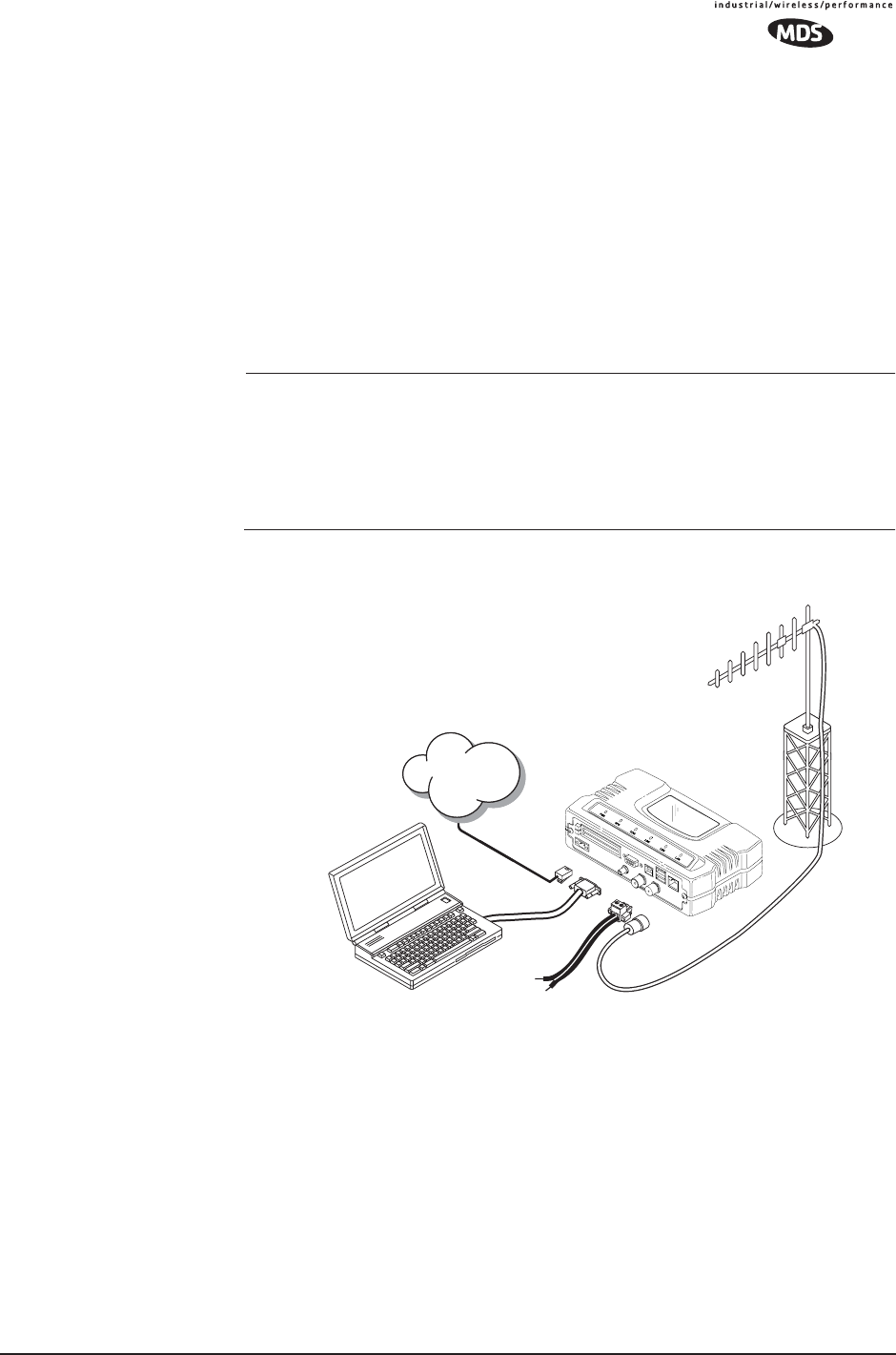
MDS 05-4446A01, Rev. A MDS Mercury User’s Guide 139
5.1 INSTALLATION PLANNING
This section provides tips for selecting an appropriate site, choosing an
antenna system, and reducing the chance of harmful interference.
5.1.1 General Requirements
There are three main requirements for installing a transceiver—ade-
quate and stable primary power, a good antenna system, and the correct
interface between the transceiver and the data device. Figure 5-1 shows
a typical Remote Gateway installation.
NOTE: The transceiver’s network port supports 10BaseT and
100BaseT connections. Confirm that your hub/switch is
capable of auto-switching data rates.
To prevent excessive Ethernet traffic from degrading perfor-
mance, place the transceiver in a segment, or behind routers.
Invisible place holder
Figure 5-1. Typical Installation with a Tower-Mounted Antenna
(Connect user data equipment to any compatible LAN or COM Port)
Unit Dimensions
Figure 5-2 shows the dimensions of the transceiver case and its
mounting holes, and Figure 5-3 on Page 140, the dimensions for
mounting with factory-supplied brackets. If possible, choose a mounting
location that provides easy access to the connectors on the end of the
radio and an unobstructed view of the LED status indicators.
POWER SUPPLY
13.8 VDC @ 580 mA (Max.)
(10.5–30 Vdc)
Negative Ground Only
COMPUTER RUNNING
TERMINAL PROGRAM
TRANSCEIVER
LOW-LOSS FEEDLINE
ANTENNA
SYSTEM
Network
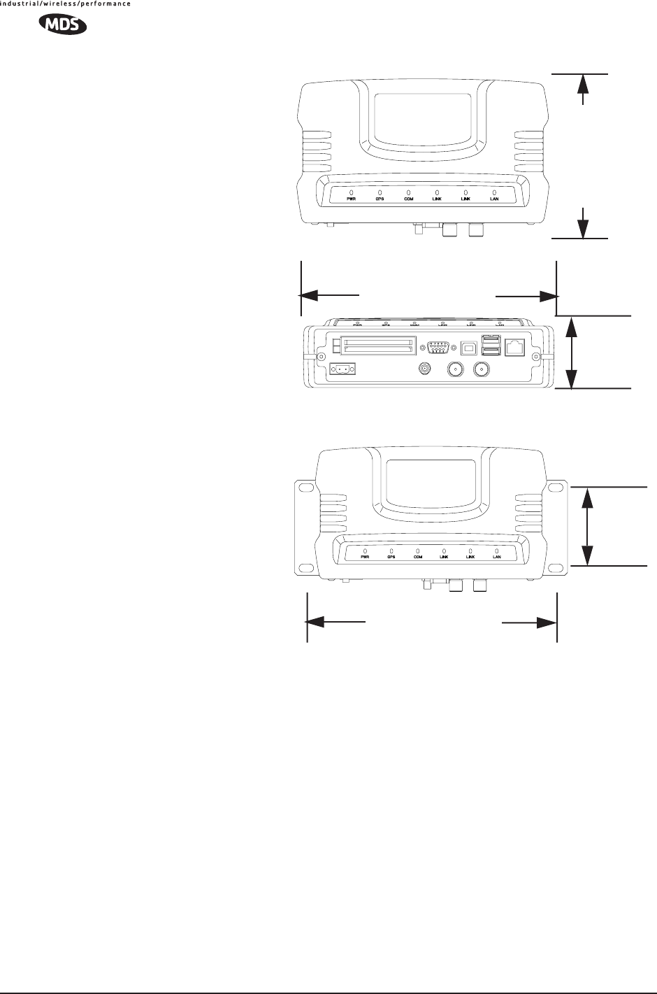
140 MDS Mercury User’s Guide MDS 05-4446A01, Rev. A
Figure 5-2. Transceiver Dimensions
Invisible place holder
Invisible place holder
Figure 5-3. Mounting Bracket Dimensions (center to center)
5.1.2 Site Selection
Suitable sites should provide:
• Protection from direct weather exposure
•A source of adequate and stable primary power
• Suitable entrances for antenna, interface or other required
cabling
• Antenna location that provides as unobstructed a transmission
path as possible in the direction of the associated station(s)
These requirements can be quickly determined in most cases. A possible
exception is the last item—verifying that an unobstructed transmission
path exists. Radio signals travel primarily by line-of-sight, and obstruc-
tions between the sending and receiving stations will affect system per-
1.4˝
6.75˝ (17.15 cm)
4.5˝ (11.43 cm)
TOP
FRONT (3.56 cm)
VIEW
VIEW
6.75˝ (17.15 cm)
1.4˝
(3.56 cm)

MDS 05-4446A01, Rev. A MDS Mercury User’s Guide 141
formance. If you are not familiar with the effects of terrain and other
obstructions on radio transmission, the discussion below will provide
helpful background.
5.1.3 Terrain and Signal Strength
While the license-free 900 MHz band offers many advantages for data
transmission services, signal propagation is affected by attenuation from
obstructions such as terrain, foliage or buildings in the transmission
path.
A line-of-sight transmission path between the central transceiver and its
associated remote site(s) is highly desirable and provides the most reli-
able communications link.
Much depends on the minimum signal strength that can be tolerated in
a given system. Although the exact figure will differ from one system to
another, a Received Signal Strength Indication (RSSI) of –80 dBm for
or stronger will provide acceptable performance in many systems.
While the equipment will work at lower-strength signals, signals
stronger than – 77 dBm provide a “fade margin” of 15 dB to account for
variations in signal strength that may occur from time-to-time. RSSI can
be measured with a terminal connected to the COM1 Port or with a HTTP
browser to the LAN (Ethernet) connector. (See “Antenna Aiming” on
Page 135 for details.)
5.1.4 Antenna & Feedline Selection
NOTE: The transceiver is a Professional Installation radio system and
must be installed by trained professional installers, or factory
trained technicians.
This text that follows is designed to aid the professional
installer in the proper methods of maintaining compliance with
FCC Part 15 limits and the +36 dBm or 4 watts peak E.I.R.P
limit.
Antennas
The equipment can be used with a number of antennas. The exact style
used depends on the physical size and layout of a system. Contact your
factory representative for specific recommendations on antenna types
and hardware sources.
In general, an omnidirectional antenna (Figure 5-4) is used at the Access
Point station site. This provides equal coverage to all of the Remote
Gateway sites.
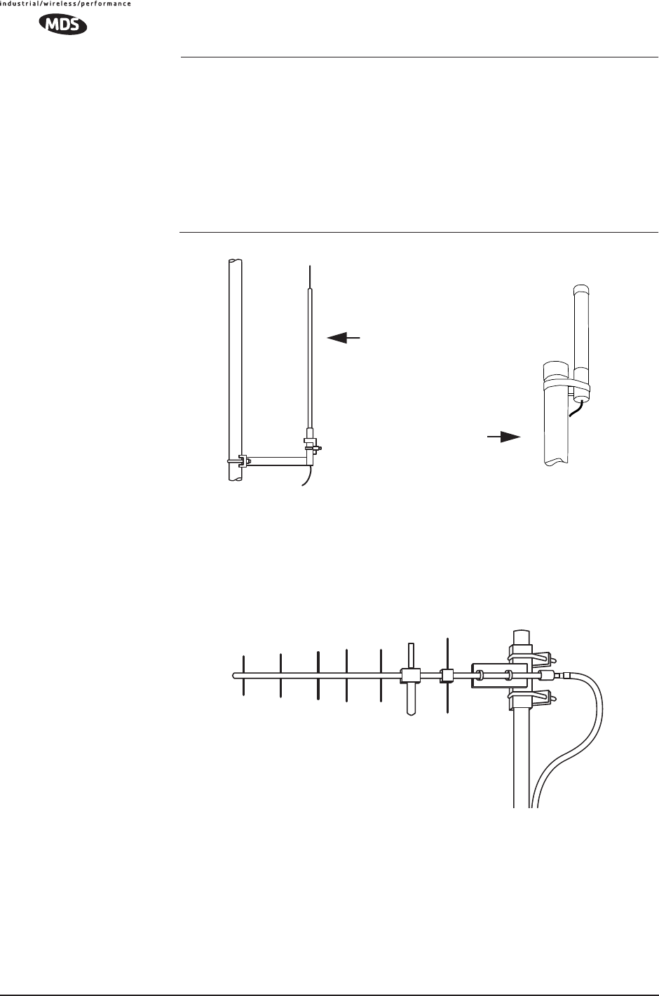
142 MDS Mercury User’s Guide MDS 05-4446A01, Rev. A
NOTE: Antenna polarization is important. If the wrong polarization is
used, a signal reduction of 20 dB or more will result. Most
systems using a gain-type omnidirectional antenna at the
Access Point station employ vertical polarization of the signal;
therefore, the remote antenna(s) must also be vertically polar-
ized (elements oriented perpendicular to the horizon).
When required, horizontally polarized omnidirectional
antennas are also available. Contact your factory representa-
tive for details.
Invisible place holder
Figure 5-4. Typical Omnidirectional Antennas
At Remote Gateway sites and units in point-to-point LANs, a directional
Yagi (Figure 5-5) antenna is generally recommended to minimize inter-
ference to and from other users. Antennas are available from a number
of manufacturers.
Invisible place holder
Figure 5-5. Typical Yagi Antenna (mounted to mast)
Feedlines
The choice of feedline used with the antenna should be carefully consid-
ered. Poor-quality coaxial cables should be avoided, as they will
degrade system performance for both transmission and reception. The
cable should be kept as short as possible to minimize signal loss.
High-gain Type
Unity-gain Type

MDS 05-4446A01, Rev. A MDS Mercury User’s Guide 143
For cable runs of less than 20 feet (6 meters), or for short range trans-
mission, an inexpensive type such as Type RG-8A/U may be acceptable.
Otherwise, we recommend using a low-loss cable type suited for
900 MHz, such as Heliax®.
Table 5-1 lists several types of popular feedlines and indicates the signal
losses (in dB) that result when using various lengths of cable at
900 MHz. The choice of cable will depend on the required length, cost
considerations, and the amount of signal loss that can be tolerated.
The tables below outline the minimum lengths of RG-214 coaxial cable
that must be used with common MDS omnidirectional antennas in order
to maintain compliance with FCC maximum limit of +36 dBi. If other
coaxial cable is used, the appropriate changes in loss figures must be
made.
NOTE: The authority to operate the transceiver in the USA may be
void if antennas other than those approved by the FCC are
used. Contact your MDS representative for additional antenna
information.
*Refer to Table 5-3 for allowable power settings of the transceiver for
each antenna type.
Table 5-1. Length vs. Loss in Coaxial Cables at 900 MHz
Cable Type 10 Feet
(3.05 m) 50 Feet
(15.24 m) 100 Feet
(30.48 m) 500 Feet
(152.4 m)
RG-214 .76 dB 3.8 dB 7.6 dB Unacceptable
Loss
LMR-400 0.39 dB 1.95 dB 3.90 dB Unacceptable
Loss
1/2 inch HELIAX 0.23 dB 1.15 dB 2.29 dB 11.45 dB
7/8 inch HELIAX 0.13 dB 0.64 dB 1.28 dB 6.40 dB
1-1/4 inch HELIAX 0.10 dB 0.48 dB 0.95 dB 4.75 dB
1-5/8 inch HELIAX 0.08 dB 0.40 dB 0.80 dB 4.00 dB
Table 5-2. Feedline Length vs. Antenna Gain*
(Required for Regulatory compliance)
Antenna
Gain (dBd) Antenna
Gain (dBi) Minimum Feedline
Length (Loss in dB) EIRP Level @
Min. Length Maxrad Antenna
Part No.
Unity (0 dB) 2.15 dBi No minimum length +32.15 dBm Omni #MFB900
3 dBd 5.15 dBi No minimum length +35.15 dBm Omni # MFB900
5 dBd 7.15 dBi 3.1 meters (1.2 dB) +35.95 dBm Omni # MFB900
6 dBd 8.15 dBi 9.1 meters (2.2 dB) +35.95 dBm Yagi # BMOY8903
10 dBd 12.15 dBi 24.7 meters (6.15 dB) +35.25 dBm Yagi # Z941

144 MDS Mercury User’s Guide MDS 05-4446A01, Rev. A
NOTE: There is no minimum feedline length required when a 6 dBi
gain or less antenna is used, as the EIRP will never exceed 36
dBm which is the maximum allowed, per FCC rules. The
transceiver’s RF output power may only be adjusted by the
manufacturer or its sub-contracted Professional Installer.
The Transceiver’s power output is factory set to maintain
compliance with the FCC’s Digital Transmission System
(DTS) Part 15 rules. These rules limit power to a maximum of
8 dBm/3 kHz, thus the Transceiver is factory set to +30 dBm.
When calculating maximum transceiver power output, use +30
dBm if the antenna gain is 6 dBi or less (36 dBm ERP). See
How Much Output Power Can be Used? below for power
control of higher gain antennas.
5.1.5 How Much Output Power Can be Used?
The transceiver is normally supplied from the factory set for a nominal
+30 dBm RF power output setting; this is the maximum transmitter
output power allowed under FCC rules. The power must be decreased
from this level if the antenna system gain exceeds 6 dBi. The allowable
level is dependent on the antenna gain, feedline loss, and the transmitter
output power setting.
NOTE: In some countries, the maximum allowable RF output may be
limited to less than the figures referenced here. Be sure to
check for and comply with the requirements for your area.
5.1.6 Conducting a Site Survey
If you are in doubt about the suitability of the radio sites in your system,
it is best to evaluate them before a permanent installation is underway.
This can be done with an on-the-air test (preferred method); or indi-
rectly, using path-study software.
An on-the-air test is preferred because it allows you to see firsthand the
factors involved at an installation site and to directly observe the quality
of system operation. Even if a computer path study was conducted ear-
lier, this test should be done to verify the predicted results.
The test can be performed by first installing a radio and antenna at the
proposed Access Point (AP) station site (one-per-system). Then visit the
Remote site(s) with another transceiver (programmed as a remote) and
a hand-held antenna. (A PC with a network adapter can be connected to
each radio in the network to simulate data during this test using the
PING command.)
With the hand-held antenna positioned near the proposed mounting
spot, a technician can check for synchronization with the Access Point
station (shown by a lit LINK LED on the front panel) and measure the

MDS 05-4446A01, Rev. A MDS Mercury User’s Guide 145
reported RSSI value. (See “Antenna Aiming” on Page 135 for details.)
If adequate signal strength cannot be obtained, it may be necessary to
mount the station antennas higher, use higher gain antennas, select a dif-
ferent site or consider installing a repeater station. To prepare the equip-
ment for an on-the-air test, follow the general installation procedures
given in this guide and become familiar with the operating instructions
found in the CHAPTER- section Page 28.
5.1.7 A Word About Radio Interference
The transceiver shares the radio-frequency spectrum with other 900
MHz services and other Part 15 (unlicensed) devices in the USA. As
such, near 100% error-free communications may not be achieved in a
given location, and some level of interference should be expected. How-
ever, the radio’s flexible design and hopping techniques should allow
adequate performance as long as care is taken in choosing station loca-
tion, configuration of radio parameters and software/protocol tech-
niques.
In general, keep the following points in mind when setting up your com-
munications network.
• Systems installed in rural areas are least likely to encounter interfer-
ence; those in suburban and urban environments are more likely to
be affected by other devices operating in the license-free frequency
band and by adjacent licensed services.
• Use a directional antenna at remote sites whenever possible.
Although these antennas may be more costly than omnidirectional
types, they confine the transmission and reception pattern to a com-
paratively narrow lobe, that minimizes interference to (and from)
stations located outside the pattern.
•If interference is suspected from a nearby licensed system (such as a
paging transmitter), it may be helpful to use horizontal polarization
of all antennas in the network. Because most other services use ver-
tical polarization in this band, an additional 20 dB of attenuation to
interference can be achieved by using horizontal polarization.
Another approach is to use a bandpass filter to attenuate all signals
outside the 900 MHz band.
• Multiple Access Point units can co-exist in proximity to each other
with only very minor interference. Each network name has a differ-
ent hop pattern. (See “Protected Network Operation using Multiple
Access Points” on Page 12.) Additional isolation can be achieved by
using separate directional antennas with as much vertical or horizon-
tal separation as is practical.
• If constant interference is present in a particular frequency zone
(collection of 8 RF channels), it may be necessary to “skip” that
zone from the radio’s hopping pattern. The radio includes built-in

146 MDS Mercury User’s Guide MDS 05-4446A01, Rev. A
software to help users identify and remove blocked frequency zones
from its hopping pattern. See Page 58 for more information on Skip
Zones.
• If interference problems persist even after skipping some zones, try
reducing the length of data streams. Groups of short data streams
have a better chance of getting through in the presence of interfer-
ence than do long streams.
• The power output of all radios in a system should be set for the low-
est level necessary for reliable communications. This lessens the
chance of causing unnecessary interference to nearby systems.
If you are not familiar with these interference-control techniques, con-
tact your factory representative for more information.
Calculating System Gain
To determine the maximum allowable power setting of the radio, per-
form the following steps:
1. Determine the antenna system gain by subtracting the feedline loss
(in dB) from the antenna gain (in dBi). For example, if the antenna
gain is 9.5 dBi, and the feedline loss is 1.5 dB, the antenna system
gain would be 8 dB. (If the antenna system gain is 6 dB or less, no
power adjustment is required.)
2. Subtract the antenna system gain from 36 dBm (the maximum
allowable EIRP). The result indicates the maximum transmitter
power (in dBm) allowed under the rules. In the example above, this
is 28 dBm.
3. If the maximum transmitter power allowed is less than 30 dBm, set
the power to the desired level using the Management System.
(Main Menu>>Radio Configuration>>RF Output Power Setpoint)
For convenience, Table 5-3 lists several antenna system gains and
shows the maximum allowable power setting of the radio. Note that a
gain of 6 dB or less entitles you to operate the radio at full power output
–30 dBm.
For assistance in the conversion of dBm to Watts, please see
dBm-WATTS-VOLTS CONVERSION CHART on Page 148.

MDS 05-4446A01, Rev. A MDS Mercury User’s Guide 147
* Most antenna manufacturers rate antenna gain in dBd in their litera-
ture. To convert to dBi, add 2.15 dB.
† Feedline loss varies by cable type and length. To determine the loss
for common lengths of feedline, see Ta b le 5-1 on Page 143.
Table 5-3. Antenna System Gain vs. Power Output Setting
Antenna System Gain
(Antenna Gain in dBi*
minus Feedline Loss in dB†)
Maximum Power Setting
(PWR command) EIRP
(in dBm)
Omni 6 (or less) 30 36
Omni 9 27 36
Yagi 12 24 36
Yagi 14 22 36
Yagi 16 20 36

148 MDS Mercury User’s Guide MDS 05-4446A01, Rev. A
5.2 dBm-WATTS-VOLTS CONVERSION
CHART
Table 5-4 is provided as a convenience for determining the equivalent
voltage or wattage of an RF power expressed in dBm.
Table 5-4. dBm-Watts-Volts conversion—for 50 ohm systems
dBm V Po
+53 100.0 200W
+50 70.7 100W
+49 64.0 80W
+48 58.0 64W
+47 50.0 50W
+46 44.5 40W
+45 40.0 32W
+44 32.5 25W
+43 32.0 20W
+42 28.0 16W
+41 26.2 12.5W
+40 22.5 10W
+39 20.0 8W
+38 18.0 6.4W
+37 16.0 5W
+36 14.1 4W
+35 12.5 3.2W
+34 11.5 2.5W
+33 10.0 2W
+32 9.0 1.6W
+31 8.0 1.25W
+30 7.10 1.0W
+29 6.40 800mW
+28 5.80 640mW
+27 5.00 500mW
+26 4.45 400mW
+25 4.00 320mW
+24 3.55 250mW
+23 3.20 200mW
+22 2.80 160mW
+21 2.52 125mW
+20 2.25 100mW
+19 2.00 80mW
+18 1.80 64mW
+17 1.60 50mW
+16 1.41 40mW
+15 1.25 32mW
+14 1.15 25mW
+13 1.00 20mW
+12 .90 16mW
+11 .80 12.5mW
+10 .71 10mW
+9 .64 8mW
+8 .58 6.4mW
+7 .500 5mW
+6 .445 4mW
+5 .400 3.2mW
+4 .355 2.5mW
+3 .320 2.0mW
+2 .280 1.6mW
+1 .252 1.25mW
dBm V Po
0 .225 1.0mW
-1 .200 .80mW
-2 .180 .64mW
-3 .160 .50mW
-4 .141 .40mW
-5 .125 .32mW
-6 .115 .25mW
-7 .100 .20mW
-8 .090 .16mW
-9 .080 .125mW
-10 .071 .10mW
-11 .064
-12 .058
-13 .050
-14 .045
-15 .040
-16 .0355
dBm mV Po
-17 31.5
-18 28.5
-19 25.1
-20 22.5 .01mW
-21 20.0
-22 17.9
-23 15.9
-24 14.1
-25 12.8
-26 11.5
-27 10.0
-28 8.9
-29 8.0
-30 7.1 .001mW
-31 6.25
-32 5.8
-33 5.0
-34 4.5
-35 4.0
-36 3.5
-37 3.2
-38 2.85
-39 2.5
-40 2.25 .1µW
-41 2.0
-42 1.8
-43 1.6
-44 1.4
-45 1.25
-46 1.18
-47 1.00
-48 0.90
dBm mV Po
-49 0.80
-50 0.71 .01µW
-51 0.64
-52 0.57
-53 0.50
-54 0.45
-55 0.40
-56 0.351
-57 0.32
-58 0.286
-59 0.251
-60 0.225 .001µW
-61 0.200
-62 0.180
-63 0.160
-64 0.141
dBm µV Po
-65 128
-66 115
-67 100
-68 90
-69 80
-70 71 .1nW
-71 65
-72 58
-73 50
-74 45
-75 40
-76 35
-77 32
-78 29
-79 25
-80 22.5 .01nW
-81 20.0
-82 18.0
-83 16.0
-84 11.1
-85 12.9
-86 11.5
-87 10.0
-88 9.0
-89 8.0
-90 7.1 .001nW
-91 6.1
-92 5.75
-93 5.0
-94 4.5
-95 4.0
-96 3.51
-97 3.2
dBm µV Po
-98 2.9
-99 2.51
-100 2.25 .1pW
-101 2.0
-102 1.8
-103 1.6
-104 1.41
-105 1.27
-106 1.18
dBm nV Po
-107 1000
-108 900
-109 800
-110 710 .01pW
-111 640
-112 580
-113 500
-114 450
-115 400
-116 355
-117 325
-118 285
-119 251
-120 225 .001pW
-121 200
-122 180
-123 160
-124 141
-125 128
-126 117
-127 100
-128 90
-129 80 .1ƒW
-130 71
-131 61
-132 58
-133 50
-134 45
-135 40
-136 35
-137 33
-138 29
-139 25
-140 23 .01ƒW

MDS 05-4446A01, Rev. A MDS Mercury User’s Guide 149

150 MDS Mercury User’s Guide MDS 05-4446A01, Rev. A

MDS 05-4446A01, Rev. A MDS Mercury User’s Guide 151
6TECHNICAL REFERENCE
6 Chapter Counter Reset Paragraph
Contents
5.1 INSTALLATION PLANNING ...................................................139
5.1.1 General Requirements ........................................................... 139
5.1.2 Site Selection ......................................................................... 141
5.1.3 Terrain and Signal Strength .................................................... 141
5.1.4 Antenna & Feedline Selection ................................................ 142
5.1.5 How Much Output Power Can be Used? ............................... 145
5.1.6 Conducting a Site Survey ...................................................... 145
5.1.7 A Word About Radio Interference ........................................... 146
5.2 dBm-WATTS-VOLTS CONVERSION CHART........................149

152 MDS Mercury User’s Guide MDS 05-4446A01, Rev. A

MDS 05-4446A01, Rev. A MDS Mercury User’s Guide 153
6.1 DATA INTERFACE CONNECTORS
Three types of data interface connectors are provided on the face of the
transceiver. The first, the LAN Port, is an RJ-45 connector. The second
are USB connectors, of which there are two Type-A and one Type-B
provided. Finally, COM1 is a DB-9 female interface connector that uses
the RS-232 (EIA-232) signaling standard.
The transceiver meets U.S.A.’s FCC Part 15, Class A limits when used
with shielded data cables.
6.1.1 LAN Port
The transceiver’s LAN Port is used to connect the radio to an Ethernet
network. The transceiver provides a data link to an Internet Pro-
tocol-based (IP) network via the Access Point station. Each radio in the
network must have a unique IP address for the network to function prop-
erly.
• To connect a PC directly to the radio’s LAN port, an RJ-45 to
RJ-45 cross-over cable is required.
• To connect the radio to a Ethernet hub or bridge, use a
straight-through cable.
The connector uses the standard Ethernet RJ-45 cables and wiring. For
custom-made cables, use the pinout information below.
Figure 6-1. LAN Port (RJ-45) Pinout
(Viewed from the outside of the unit)
Table 6-1. LAN Port (IP/Ethernet)
Pin Functions Ref.
1 Transmit Data (TX) High
2 Transmit Data (TX) Low
3 Receive Data (RX) High
4 Unused
5 Unused
6 Receive Data (RX) Low
7 Unused
8 Unused
CAUTION
RADIO FREQUENCY
INTERFERENCE
POTENTIAL
1 2 3 4 5 6 7 8
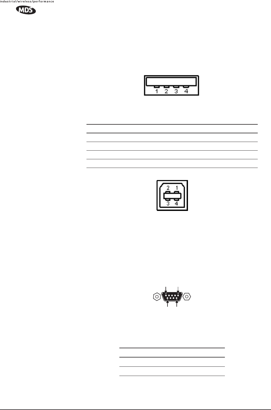
154 MDS Mercury User’s Guide MDS 05-4446A01, Rev. A
6.1.2 USB Ports
The transceiver contains two USB Type-A connectors (see Figure 6-2)
and one USB Type-B connector (see Figure 6-3). These ports conforms
to version 1.1 of the USB standard. The pin functions for this connector
are provided in the table below.
Figure 6-2. USB Type-A Connector
(As viewed from the outside of the unit)
Invisible place holder
Figure 6-3. USB Type-B Connector
6.1.3 COM1 Port
To connect a PC to the transceiver’s COM1 port use a DB-9M to DB-9F
“straight-through” cable. These cables are available commercially, or
may be constructed using the pinout information in Figure 6-4 and
Table 6-2.
Figure 6-4. COM1 Port (DCE)
(Viewed from the outside of the unit.)
Pin Signal Name Description Std. Cable Color
1 PC_USB_+5V +5 Vdc Red
2 USBD– USB Data Minus White
3 USBD+ USB Data Plus Green
4 Ground Chassis Ground Black
Table 6-2. COM1 Port Pinout, DB-9F/RS-232 Interface
Pin Functions DCE
1 Unused
2 Receive Data (RXD) <—[ Out
1
5
96

MDS 05-4446A01, Rev. A MDS Mercury User’s Guide 155
6.2 FUSE REPLACEMENT
PROCEDURE
An internal fuse protects the transceiver from over-current conditions or
an internal component failure. It should not be replaced until you are
certain you are in a safe (non-flammable) environment.
1. Disconnect the primary power source and all other connections to
the unit.
2. Place the radio on its back and remove the four Phillips screws on
the bottom cover.
3. Carefully separate the top and bottom covers. There is a flat ribbon
cable between the top cover’s LEDs and the unit motherboard. You
do not need to disconnect the ribbon cable.
4. Locate the fuse and fuse holder on the transceiver’s PC board. See
Figure 6-5 for details.
5. Loosen the fuse from the holder using a very small screwdriver. Use
a small pair of needle-nose pliers to pull the fuse straight up and
remove it.
6. Using an Ohmmeter, or other continuity tester, verify the fuse is
blown.
7. Install a new fuse by reversing the process.
Littelfuse P/N: 0454002; 452 Series, 2 Amp SMF Slo-Blo
MDS P/N: 29-1784A03
8. Install the covers and check the transceiver for proper operation.
3 Transmit Data (TXD) —>[ In
4 Unused
5 Signal Ground (GND)
6–9 Unused
Figure 6-5.
Internal Fuse and Holder
Assembly
Table 6-2. COM1 Port Pinout, DB-9F/RS-232 Interface
Pin Functions DCE

156 MDS Mercury User’s Guide MDS 05-4446A01, Rev. A
Invisible place holder
6.3 TECHNICAL SPECIFICATIONS
GENERAL
Temperature Range: –40° C to +60° C (–40° F to 158° F)
Humidity: 95% at +40° C (104° F); non-condensing
Primary Power: 10.5–30 Vdc (13.8 Vdc Nominal)
External Power Supply Options: 110–120/210–220 Vac
Supply Current (TX): AP: 14.5 Watts @ 1 Watt RF Output
Remote: 3.2 watts @ 1 Watt RF Output
Supply Current (RX): AP: 4 Watts
Remote: 3 watts
MTBF: 35 Years (Telcordia Method 1, Case 3)
Size (Excluding mtg. hardware): 5.72 x 20 x 12.38 cm (H x W x D)
(2.25" x 7.88" x 4.88" in)
Mounting w/Optional Hardware: • DIN Rail
• Flat surface mounting brackets
• 19” rack tray (2U high)
Weight: 0.91 kg / 2 lb
Case: Die Cast Aluminum
Boot Time: ≈ 45 sec
Time Required to Associate
with Access Point: ≈ 20 sec
APPROVALS/HOMOLOGATION
• FCC Part 15.247
FCC identifier: E5MDS-Mercury 900
• Industry Canada RSS-210
Certification no.: 3738A-Mercury 900
• CSA/US Class 1, Div. 2; Groups A, B, C and D
hazardous locations
• Contact factory for information on availability and
governmental approvals in other countries
MANAGEMENT
• HTTP (Embedded Web server)
• Telnet, local console
• SNMP v1/v2/v3
• MIB II
• Enterprise MIB
• SYSLOG
• MDS NETview MS compatible
DATA CHARACTERISTICS
PORTS:

MDS 05-4446A01, Rev. A MDS Mercury User’s Guide 157
Ethernet Interface: • 10/100BaseT, RJ-45 Standard
• IEEE 802.3, Spanning Tree (Bridging), IGMP, IP
(DHCP, ICMP, UDP, TCP, ARP)
Raw Bit Rate (LAN port): 12.7 Mbps–64 QAM
4.8 Mbps–16 QAM
2.4 Mbps–QPSK
.2 Mbps–BPSK
Serial Interface (COM1):
Signaling Standard: EIA-232/V.24
Interface Connector: DB-9F
Interface: • DCE
• Encapsulation over IP (tunneling) for serial async
multidrop protocols
Data Rate: 1200–115,200 bps
asynchronous
Data Latency: < 10 ms typical
Byte Formats: 7 or 8-bit; even, odd, or no-parity; 1 or 2 stop bits
Other Interfaces: Two CardBus Slots
USB Device and host ports
Built-in GPS (Optional)
LEDs: PWR, COM1, LINK, USB, LAN
OPERATING MODES: Configurable as Access Point or Remote Station
CONFIGURATIONS:: Serial and Ethernet
Remote Serial Gateway
Serial only
Remote Ethernet Bridge
Ethernet only (with multi-drop capability)
:PROTOCOLS: • Wireless: CSMA/CA (Collision Avoidance)
• Ethernet: IEEE 802.3, Ethernet II, Spanning Tree
(Bridging), IGMP
• TCP/IP: DHCP, ICMP, UDP, TCP, ARP, Multicast,
SNTP, TFTP
• Serial: PPP, Encapsulation over IP (tunneling) for
serial async multidrop protocols including
Modbus, DNP.3, DF1, BSAP
• Special: Allen-Bradley EtherNet/IP* -
Modbus/TCP (optional)
CYBER SECURITY
• MDS Cyber Security Suite,
Level 1: • AES-128 encryption (optional)
• MDS Cyber Security Suite,
Level 2: • RC4-128 encryption
•Automatic rotating key algorithm
•Authentication: 802.1x, RADIUS, EAP/TLS, PKI,
PAP, CHAP
•Management: SSL, SSH, HTTPS
•Approved AP/Remotes list (local authentication)
•Failed login lockdown
•900 MHz operation and proprietary data framing
RADIO CHARACTERISTICS
GENERAL:

158 MDS Mercury User’s Guide MDS 05-4446A01, Rev. A
Frequency Range: 902–928 MHz ISM Band
Frequency Hopping Range: Five user-configurable 2.5 MHz-wide zones,
each containing 5 frequencies
Hop Patterns: 8192, based on network name
Frequency Stability: 20 ppm
Antenna Connectors: TX/RX and RX (diversity)—TNC
GPS—Female SMA
TRANSMITTER:
Power Output
(at antenna connector): 0.1 to 1.0 watt (+20 dBm to +30 dBm) ±1.0 dB, set
by user
Duty Cycle: Continuous
Modulation Type: Orthogonal Frequency Division Multiplex (OFDM)
Output Impedance: 50 Ohms
Spurious: –67 dBc
Occupied Bandwidth
(data channels): +/- 3 MHz wide data channels
RECEIVER:
Type: Double conversion superheterodyne
Sensitivity: –86 dBm through –101 dBm with 10-6 BER
Intermodulation: 59 dB Minimum (EIA)
Desensitization: 70 dB
Spurious: 60 dB
TRANSMIT/RECEIVE RANGE (Nominal)
512 kbps
Fixed Range (typical): 15 miles (24 km)
Fixed Range (maximum): 60 miles (97 km)
Mobile Range (parked): 5 miles (8 km)
Mobile Range (moving): 3 miles (5 km)
1.5 Mbps
Fixed Range (typical): 8 miles (13 km)
Fixed Range (maximum): 15 miles (24 km)
Note: Specifications subject to change without notice or obligation.

MDS 05-4446A01, Rev. A MDS Mercury User’s Guide 159
NOTE: Range calculations for fixed locations assume a 6 dBd gain
Omnidirectional antenna on a 100 ft tower at the AP, a 10 dBd
gain Yagi on a 25 ft mast at the remote with output power
decreased to yield maximum allowable EIRP (36 dBm), a 10
dB fade margin, and a mix of agricultural and commercial
terrain with line of sight.
Range calculations for mobile units assume a 6 dBd gain Omni
on a 100 ft tower at the AP, a 5 dBd gain Omni with 1 watt
output power at 6 ft height, a 10 dB fade margin, and 90%
confidence with near line-of-sight in a mix of agricultural and
commercial terrain.
Actual performance is dependent on many factors including
antenna height, blocked paths, and terrain.
6.4 CHANNEL TABLE
The transceiver operates on x channels, numbered 0 to x as listed in
Table 6-3. (Channel info to be supplied.)
6.5 SNMP USAGE NOTES
6.5.1 Overview
The firmware release described in this manual contains major changes
to the transceiver’s SNMP Agent, several new MIB variables, and new
Table 6-3. Channel Table
Zone Channel Frequency
0 902.5000
1 902.8165
2 903.1330
3 903.4495
4 903.7660
5 904.0825
6 904.3990
7 904.7155
8 905.0320
9 905.3485
10 905.6650

160 MDS Mercury User’s Guide MDS 05-4446A01, Rev. A
Agent configuration options. This guide reviews the changes and shows
how to properly configure the Agent to take advantage of these new fea-
tures.
SNMPv3 Support
The updated SNMP Agent now supports SNMP version 3 (SNMPv3).
The SNMPv3 protocol introduces Authentication (MD5/SHA-1),
Encryption (DES), the USM User Table, and View-Based Access
(Refer to RFC2574 for full details). The SNMP Agent has limited
SNMPv3 support in the following areas:
• Only MD5 Authentication is supported (no SHA-1). SNMPv3
provides support for MD5 and SHA-1. Currently, only MD5
Authentication is supported in the SNMP Agent.
• Limited USM User Table Manipulation. The SNMP Agent
starts with 5 default accounts. New accounts can be added
(SNMPv3 adds new accounts by cloning existing ones), but
they will be volatile (will not survive a power-cycle).
New views cannot be configured on the SNMP Agent. Views
will be inherited for new accounts from the account that was
cloned.
The SNMP Agent uses one password pair (Authentication / Pri-
vacy) for all accounts. This means that when the passwords
change for one user, they change for all users.
SNMPv3 Accounts
The following default accounts are available for the SNMP Agent:
enc_mdsadmin—Read/write account using Authentication and Encryp-
tion
auth_mdsadmin—Read/write account using Authentication
enc_mdsviewer—Read only account using Authentication and Encryp-
tion
auth_mdsviewer—Read only account using Authentication
def_mdsviewer—Read only account with no Authentication or Encryp-
tion
Context Names
The following Context Names are used (please refer to RFC2574 for full
details):
Admin accounts: context_a / Viewer accounts: context_v
All accounts share the same default passwords:

MDS 05-4446A01, Rev. A MDS Mercury User’s Guide 161
Authentication default password: MDSAuthPwd / Privacy default pass-
word: MDSPrivPwd
Passwords can be changed either locally (via the console) or from an
SNMP Manager, depending on how the Agent is configured. If pass-
words are configured and managed locally, they are non-volatile and
will survive a power-cycle. If passwords are configured from an SNMP
manager, they will be reset to whatever has been stored for local man-
agement on power-cycle.
This behavior was chosen based on RFC specifications. The SNMP
Manager and Agent don’t exchange passwords, but actually exchange
keys based on passwords. If the Manager changes the Agent’s password
the Agent doesn’t know the new password; just the new key. In this case,
only the Manager knows the new password. This could cause problems
if the Manager loses the password. If that happens, the Agent becomes
unmanageable. Resetting the Agent’s passwords (and therefore keys) to
what is stored in flash memory upon power-cycle prevents the serious
problem of losing the Agent’s passwords.
If passwords are managed locally, they can be changed on the Agent (via
the console). Any attempts to change the passwords for the Agent via an
SNMP Manager will fail when the Agent is in this mode. Locally
defined passwords will survive a power-cycle.
In either case, the SNMP Manager needs to know the initial passwords
that are being used in order to talk to the Agent. If the Agent’s passwords
are configured via the Manager, then they can be changed from the Man-
ager. If the passwords are managed locally, then the Manager must be
re-configured with any password changes in order to continue to talk to
the Agent.
Password-Mode Management Changes
When the password management mode is changed, the active passwords
used by the Agent may also change. Some common scenarios are dis-
cussed below:
Common Scenarios • Passwords are currently being handled by the Manager. The
assigned passwords are Microwave (Auth), and Rochester (Priv).
Configuration is changed to manage the passwords locally. The
passwords stored on the radio were Fairport (Auth), and
Churchville (Priv) (If local passwords have never been used,
then MDSAuthPwd and MDSPrivPwd will be used). These
passwords will now be used by the Agent to re-generate keys.
The Manager will need to know these passwords in order to talk
to the Agent.

162 MDS Mercury User’s Guide MDS 05-4446A01, Rev. A
•Passwords are currently being managed locally. The local pass-
words are Fairport (Auth) and Churchville (Priv). Configuration is
changed to handle the passwords from the Manager. The same
passwords will continue to be used, but now the Manager can
change them.
•Passwords are currently being managed locally. The local pass-
words are Fairport (Auth) and Churchville (Priv). Passwords are
changed to Brighton (Auth) and Perinton (Priv). The Agent will
immediately generate new keys based on these passwords and
start using them. The Manager will have to be re-configured to
use these new passwords.
•Passwords are currently being managed locally. The local pass-
words are Fairport (Auth) and Churchville (Priv). Configuration is
changed to handle the passwords from the Manager. The Man-
ager changes the passwords to Brighton (Auth) and Perinton
(Priv). The radio is then rebooted. After a power-cycle, the radio
will use the passwords stored in flash, which are Fairport (Auth)
and Churchville (Priv). The Manager will have to be re-config-
ured to use these new passwords.
Table 6-4. SNMP Traps (Sorted by Code)
SNMP Trap Severity Description
systemBoot(32) INFORM SNR Within threshold/Below threshold
systemReboot(33) MAJOR Telnet User Logged Out/Logged In
startScan(34) INFORM Reprogramming Started
rxBeaconErrored(35) INFORM Received Beacon - Netname Does Not Match
rxBeaconWrongNetworkName (36) INFORM Received Beacon - AP is Blacklisted
rxBeaconFromBlacklistAP(37) MAJOR Max Beacon Wait Time Exceeded
expectedSync(38) INFORM Expected Sync Lost/Established
hopSync(39) INFORM Hop Sync Lost/Established
snr(41) INFORM Scanning Started
ber(42) INFORM Bit Error Rate Below threshold/Above threshold
associated(43) MAJOR Association Lost/Established
apParmChange(44) MINOR Association Lost - AP Hop Parameter Changed
reprogStarted(45) MAJOR Reprogramming Failed
reprogComplete(46) MAJOR Rem Ethernet Link Connected/Disconnected
reprogFailed(47) INFORM Reprogramming Complete
telnetLogin(48) MAJOR Telnet Access Locked for 5 Min
httpLogin(49) MAJOR HTTP User Logged Out/Logged In
countrySkipZoneMismatch(50) INFORM Country/SkipZone Mismatch
desiredAPIPMismatch(51) INFORM Desired AP IP Addr Mismatch
eventLogCleared(52) INFORM Log Cleared

MDS 05-4446A01, Rev. A MDS Mercury User’s Guide 163
authDemoMode(53) MAJOR Auth Demo Mode Expired -- Rebooted
Radio/Enabled
keyEntered(54) MAJOR Auth Key Entered - Key Valid/Key Invalid
apEthLinkDown(55) MAJOR Association Lost - AP's Ethernet Link Down
noBeacons(56) MAJOR MAC Param Changed
apNotApproved(57) MAJOR Current AP No Longer Approved
netnameChanged(58) MAJOR Association Lost - Local Network Name Changed
ipAddrChanged(59) MAJOR Association Lost - Local IP Address Changed
assocTryFail(60) MAJOR Association Attempt Success/Failed
remEthLinkLost(61) INFORM Received Beacon - Valid/Errored
consoleLogin(62) MAJOR Console User Logged Out/Logged In
consoleLockdown(63) MAJOR Console Access Locked for 5 Min
telnetLockdown(64) INFORM System Bootup (power on)
httpLockdown(65) MAJOR HTTP Access Locked for 5 Min
eventRemote(66) INFORM Remote added/removed from internal database
eventEndpoint(67) INFORM Endpoint added/removed from internal database
routeAdded(68) INFORM Radio attempted but failed to add a route to its
internal routing table
routeDeleted(69) INFORM Radio attempted but failed to delete a route from its
internal routing table
sinRemSwitch(70) INFORM Remote mode was switched (serial to ethernet,
ethernet to serial)
ChanCnt(71) INFORM Number of channels defined does not match
(Channel 130 only)
tftpConnection(73) INFORM TFTP Server on AP started or finished a transfer
apNetNameChanged(74) MAJOR Remote lost association due to a change in the
AP’s netname
ipConnectivityOK(75) INFORM Radio is associated AND 1) has an IP address
statically defined, OR 2) received an IP address via
DHCP
compressionChanged(76) INFORM Compression state has changed (enabled,
disabled)
macDecryptError(77) INFORM MAC has received a packet that it could not decrypt
lanPortStatus(78) INFORM Ethernet port has changed (enabled, disabled)
tftpConnFailed(79) INFORM TFTP server on AP failed to transfer
sdbError(80) INFORM AP encountered an internal database error
Table 6-4. SNMP Traps (Sorted by Code) (Continued)
SNMP Trap Severity Description

164 MDS Mercury User’s Guide MDS 05-4446A01, Rev. A

MDS 05-4446A01, Rev. A MDS Mercury User’s Guide 165
7GLOSSARY OF TERMS
AND ABBREVIATIONS
7 Chapter Counter Reset Paragraph
If you are new to wireless IP/Ethernet systems, some of the terms used
in this guide may be unfamiliar. The following glossary explains many
of these terms and will prove helpful in understanding the operation of
your radio network.
Access Point (AP)—The transceiver in the network that provides syn-
chronization information to one or more associated Remote units. AP
units may be configured for either the Access Point (master) or Remote
services. (See “Network Configuration Menu” on Page 44.)
Active Scanning—See Passive Scanning
Antenna System Gain—A figure, normally expressed in dB, repre-
senting the power increase resulting from the use of a gain-type antenna.
System losses (from the feedline and coaxial connectors, for example)
are subtracted from this figure to calculate the total antenna system gain.
AP—See Access Point
Association—Condition in which the frequency hopping pattern of the
Remote is synchronized with the Access Point station and is ready to
pass traffic.
Authorization Key—Alphanumeric string (code) that is used to enable
additional capabilities in the transceiver.
Bit—The smallest unit of digital data, often represented by a one or a
zero. Eight bits (plus start, stop, and parity bits) usually comprise a byte.
Bits-per-second—See BPS.
BPDU—Bridge Protocol Data Units
BPS—Bits-per-second (bps). A measure of the information transfer rate
of digital data across a communication channel.
Byte—A string of digital data usually made up of eight data bits and
start, stop and parity bits.
CSMA/CA—Carrier Sense Multiple Access/Collision Avoidance
CSMA/CD—Carrier Sense Multiple Access/Collision Detection
Cyclic Redundancy Check (CRC)—A technique used to verify data
integrity. It is based on an algorithm which generates a value derived

166 MDS Mercury User’s Guide MDS 05-4446A01, Rev. A
from the number and order of bits in a data string. This value is com-
pared with a locally-generated value and a match indicates that the mes-
sage is unchanged, and therefore valid.
Data Circuit-terminating Equipment—See DCE.
Data Communications Equipment—See DCE.
Datagram—A data string consisting of an IP header and the IP message
within.
Data Terminal Equipment—See DTE.
dBi—Decibels referenced to an “ideal” isotropic radiator in free space.
Frequently used to express antenna gain.
dBm—Decibels referenced to one milliwatt. An absolute unit used to
measure signal power, as in transmitter power output, or received signal
strength.
DCE—Data Circuit-terminating Equipment (or Data Communications
Equipment). In data communications terminology, this is the “modem”
side of a computer-to-modem connection. COM1 Port of the transceiver
is set as DCE.
Decibel (dB)—A measure of the ratio between two signal levels. Fre-
quently used to express the gain (or loss) of a system.
Delimiter—A flag that marks the beginning and end of a data packet.
Device Mode—The operating mode/role of a transceiver (Access Point
or Remote) in a wireless network.
DHCP (Dynamic Host Configuration Protocol)—An Internet stan-
dard that allows a client (i.e. any computer or network device) to obtain
an IP address from a server on the network. This allows network admin-
istrators to avoid the tedious process of manually configuring and man-
aging IP addresses for a large number of users and devices. When a
network device powers on, if it is configured to use DHCP, it will con-
tact a DHCP server on the network and request an IP address.
The DHCP server will provide an address from a pool of addresses allo-
cated by the network administrator. The network device may use this
address on a “time lease” basis or indefinitely depending on the policy
set by the network administrator. The DHCP server can restrict alloca-
tion of IP addresses based on security policies. An Access Point may be
configured by the system administrator to act as a DHCP server if one
is not available on the wired network.
Digital Signal Processing—See DSP.

MDS 05-4446A01, Rev. A MDS Mercury User’s Guide 167
DSP—Digital Signal Processing. DSP circuitry is responsible for the
most critical real-time tasks; primarily modulation, demodulation, and
servicing of the data port.
DTE—Data Terminal Equipment. A device that provides data in the
form of digital signals at its output. Connects to the DCE device.
Encapsulation—Process in by which, a complete data packet, such as
Modbus frame or any other polled asynchronous protocol frame, is
placed in the data portion of another protocol frame (in this case IP) to
be transported over a network. Typically this action is done at the receiv-
ing end, before being sent as an IP packet to a network. A similar re-
versed process is applied at the other end of the network extracting the
data from the IP envelope, resulting in the original packet in the original
protocol.
Endpoint—IP address of data equipment connected to the ports of the
radio.
Equalization—The process of reducing the effects of amplitude, fre-
quency or phase distortion with compensating networks.
Fade Margin—The greatest tolerable reduction in average received
signal strength that will be anticipated under most conditions. Provides
an allowance for reduced signal strength due to multipath, slight antenna
movement or changing atmospheric losses. A fade margin of 15 to 20
dB is usually sufficient in most systems.
Fragmentation—A technique used for breaking a large message down
into smaller parts so it can be accommodated by a less capable media.
Frame—A segment of data that adheres to a specific data protocol and
contains definite start and end points. It provides a method of synchro-
nizing transmissions.
Frequency Hopping—The spread spectrum technique used by the
transceiver, where two or more associated radios change their operating
frequencies several times per second using a set pattern. Since the pat-
tern appears to jump around, it is said to “hop” from one frequency to
another.
Frequency Zone—The radio uses up to 80 discrete channels in the 902
to 928 MHz spectrum. A group of 8 channels is referred to as a zone; in
total there are 10 zones.
Hardware Flow Control—A transceiver feature used to prevent data
buffer overruns when handling high-speed data from the connected data
communications device. When the buffer approaches overflow, the
radio drops the clear-to-send (CTS) line, that instructs the connected
device to delay further transmission until CTS again returns to the high
state.

168 MDS Mercury User’s Guide MDS 05-4446A01, Rev. A
Hop Pattern Seed—A user-selectable value to be added to the hop pat-
tern formula in an unlikely event of nearly identical hop patterns of two
collocated or nearby radio networks to eliminate adjacent-network inter-
ference.
Host Computer—The computer installed at the master station site, that
controls the collection of data from one or more remote sites.
HTTP—Hypertext Transfer Protocol
IAPP (inter-Access Point Protocol)—A protocol by which access
points share information about the stations that are connected to them.
When a station connects to an access point, the access point updates its
database. When a station leaves one access point and roams to another
access point, the new access point tells the old access point, using IAPP,
that the station has left and is now located on the new access point.
ICMP—Internet Control Message Protocol
IGMP (Internet Gateway Management Protocol)—Ethernet level
protocol used by routers and similar devices to manage the distribution
of multicast addresses in a network.
IEEE—Institute of Electrical and Electronic Engineers
Image (File)—Data file that contains the operating system and other
essential resources for the basic operation of the radio’s CPU.
LAN—Local Area Network
Latency—The delay (usually expressed in milliseconds) between when
data is applied at the transmit port at one radio, until it appears at the
receive port at the other radio.
MAC—Media Access Controller
MD5—A highly secure data encoding scheme. MD5 is a one-way hash
algorithm that takes any length of data and produces a 128 bit “finger-
print.” This fingerprint is “non-reversible,” it is computationally infea-
sible to determine the file based on the fingerprint. For more details
review “RFC 1321” available on the Internet.
MIB—Management Information Base
Microcontroller Unit—See MCU.
Mobile IP—An emerging standard by which access points and stations
maintain network connectivity as the stations move between various IP
networks. Through the use of Mobile IP a station can move from its
home IP network to a foreign network while still sending and receiving
data using it's original IP address. Other hosts on the network will not
need to know that the station is no longer in its home network and can

MDS 05-4446A01, Rev. A MDS Mercury User’s Guide 169
continue to send data to the IP address that was assigned to the station.
Mobile IP also uses DHCP when the station moves into a foreign net-
work.
Mobility—Refers to a station that moves about while maintaining
active connections with the network. Mobility generally implies phys-
ical motion. The movement of the station is not limited to a specific net-
work and IP subnet. In order for a station to be mobile it must establish
and tear down connections with various access points as it moves
through the access points' territory. To do this, the station employs
roaming and Mobile IP.
Mode—See Device Mode.
MTBF—Mean-Time Between Failures
Multiple Address System (MAS)—See Point-Multipoint System.
Network Name—User-selectable alphanumeric string that is used to
identify a group of radio units that form a communications network. The
Access Point and all Remotes within a given system should have the
same network address.
Network-Wide Diagnostics—An advanced method of controlling and
interrogating MDS radios in a radio network.
NTP—Network Time Protocol
Packet—The basic unit of data carried on a link layer. On an IP net-
work, this refers to an entire IP datagram or a fragment thereof.
Passive Scanning—Scanning is a process used by stations to detect
other access points on network to which it may connect if it needs to
roam. Passive scanning is a slower process in which it listens for infor-
mation offered by the access points on a regular basis. Active scanning
is a faster process in which the station sends out probe message to which
the access points respond. Passive scanning can be done while main-
taining the current network connectivity. Active scanning affects the RF
configuration of the radio and therefore, at least temporarily, discon-
nects the station from the access point.
PING—Packet INternet Groper. Diagnostic message generally used to
test reachability of a network device, either over a wired or wireless net-
work.
Point-Multipoint System—A radio communications network or
system designed with a central control station that exchanges data with
a number of remote locations equipped with terminal equipment.
Poll—A request for data issued from the host computer (or master PLC)
to a remote radio.

170 MDS Mercury User’s Guide MDS 05-4446A01, Rev. A
Portability—A station is considered connected when it has successfully
authenticated and associated with an access point. A station is consid-
ered authenticated when it has agreed with the access point on the type
of encryption that will be used for data packets traveling between them.
The process of association causes a station to be bound to an access
point and allows it to receive and transmit packets to and from the access
point. In order for a station to be associated it must first authenticate
with the access point. The authentication and association processes
occur automatically without user intervention.
Portability refers to the ability of a station to connect to an access point
from multiple locations without the need to reconfigure the network set-
tings. For example, a remote transceiver that is connected to an access
point may be turned off, moved to new site, turned back on, and,
assuming the right information is entered, can immediately reconnect to
the access point without user intervention.
PLC—Programmable Logic Controller. A dedicated microprocessor
configured for a specific application with discrete inputs and outputs. It
can serve as a host or as an RTU.
PuTTY—A free implementation of Telnet and SSH for Win32 and
Unix platforms. It is written and maintained primarily by Simon Tatham
Refer to http://www.pobox.com/~anakin/ for more information.
Remote—A transceiver in a network that communicates with an asso-
ciated Access Point.
Remote Terminal Unit—See RTU.
RFI—Radio Frequency Interference
Roaming—A station's ability to automatically switch its wireless con-
nection between various access points (APs) as the need arises. A station
may roam from one AP to another because the signal strength or quality
of the current AP has degraded below what another AP can provide.
When two access points are co-located for redundancy, roaming allows
the stations to switch between them to provide a robust network.
Roaming may also be employed in conjunction with Portability where
the station has been moved beyond the range of the original AP to which
it was connected. As the station comes in range of a new AP, it will
switch its connection to the stronger signal. Roaming refers to a station's
logical, not necessarily physical, move between access points within a
specific network and IP subnet.
RSSI—Received Signal Strength Indicator
RTU—Remote Terminal Unit. A data collection device installed at a
remote radio site.

MDS 05-4446A01, Rev. A MDS Mercury User’s Guide 171
SCADA—Supervisory Control And Data Acquisition. An overall term
for the functions commonly provided through an MAS radio system.
Skip Zone(s)—Groups of operating channels (frequencies) deleted
from the radio transmitter and receiver operating range.
SNMP—Simple Network Management Protocol
SNR—Signal-to-Noise Ratio. A measurement of the desired signal to
ambient noise levels.This measurement provides a relative indication of
signal quality. Because this is a relative number, higher signal-to-noise
ratios indicate improved performance.
SNTP—Simple Network Time Protocol
SSL—Secure Socket Layer
SSH—Secure Shell
STP—Spanning Tree Protocol
Standing-Wave Ratio—See SWR.
SWR—Standing-Wave Ratio. A parameter related to the ratio between
forward transmitter power and the reflected power from the antenna
system. As a general guideline, reflected power should not exceed 10%
of the forward power (≈ 2:1 SWR).
TCP—Transmission Control Protocol
TFTP—Trivial File Transfer Protocol
Trap Manager—Software that collects SNMP traps for display or log-
ging of events.
UDP—User Datagram Protocol
UTP—Unshielded Twisted Pair
WINS—Windows Internet Naming Service. Part of Microsoft Win-
dows NT and 2000 servers that manages the association of workstation
names and locations with Internet Protocol addresses. It works without
the user or an administrator having to be involved in each configuration
change. Similar to DNS.
Zone—See Frequency Zone.

172 MDS Mercury User’s Guide MDS 05-4446A01, Rev. A

MDS 05-4446A01, Rev. A MDS Mercury User’s Guide i
INDEX
Numerics
100BaseT 139
10BaseT 139
802.11b 8
A
Access Point (AP), defined 167
accessories 15
Active Scanning, defined 167, 171
Actual Data Rate 87
Add Associated Remotes 83
AgeTime 94, 95
alarm conditions 128
correcting 130
Alarmed 126
Antenna
aiming 135
directional 146
Minimum Feedline Length versus Antenna Gain 144
omnidirectional 143
polarization 142
selection 142
SWR check 134
system gain 167
system gain vs. power output setting 148
system gain, defined 167
Yagi 143
AP
Auto Upgrade 94
Reboot when Upgraded 94
application
IP-to-Serial 73
Mixed-Modes 78
Point-to-Multipoint Serial-to-Serial 75
Point-to-Point Serial-to-Serial 74
Serial Port 78
Approved
Access Points/Remotes List 81
Remotes/Access Points List 82
Associated 126
Association
Date 94
defined 167
Process 93
Time 94
attenuation 22
Auth Traps Status 52
Authorization Key 116, 119
defined 167
Authorized Features 116
Auto Data Rate Menu
RSSI Threshold/Delta 57
SNR Threshold/Delta 57
Auto Key Rotation 81
Auto-Upgrade/Remote-Reboot 116
B
Backhaul
for Serial Radio Networks 7
Network 7
bandpass filter 146
Beacon
Period 54, 100, 101
signal 93
Begin Wizard 65
Bit, defined 167
Bits-per-second (bps), defined 167
BPDU 98
defined 167
BPS, defined 167
Bytes
defined 167
in on port 97
in on socket 97
out on port 97
out on socket 97
received 91, 92
sent 91, 92
C
cable
Ethernet crossover 23
feedlines 143
serial 23
Clear
Com# statistics 97
Ethernet stats 92
Log 89
Wireless stats 92
Collocating Multiple Radio Networks 13
Commit Changes and Exit Wizard 67, 69, 70, 72, 73
compression 53, 101
Computer
host, defined 170
configuration 23, 67, 68, 70, 71, 72
basic device parameters 42
defaults 23
DHCP server 48
editing files 114
Ethernet Port 47
file 108, 123
IP address 46
network 44
PPP Mode 72
radio parameters 52
scripts 107, 108
security 79
serial interfaces 62
SNMP Agent 50
TCP Mode 69
UDP mode 66
Connection Status 93
connectors 153
Contact 43

ii iNET Series User’s Guide MDS 05-4446A01, Rev. A
cost of deployment 8
Count 119
CRC (Cyclic Redundancy Check), defined 167
CSMA
CA, defined 167
CD, defined 167
Current
Alarms 89
AP IP Address 94
AP Mac Address 94
Custom Data Buffer Size 67, 69, 70, 72, 73
D
data
baud 72
baud rate 67, 68, 70, 71
buffering 64, 70
compression 101
rate 53
Database
Logging 46
Timeout 46
Datagram, defined 168
DataRate 95
Date 43
Format 43
dB, defined 168
dBi, defined 168
dBm
defined 168
watts-volts conversion 149
DCE, defined 168
default gateway 46
defaults
reset to factory 119
Delete
All Remotes 83
Remote 82
Delimiter, defined 168
deployment costs 8
Description 43
Device
IP Address 72
Mode 40, 44, 45
Mode, defined 168
Name 40, 43
Status 40, 126
DHCP 46, 47
defined 168
Netmask 49
Server Configuration 45
Diagnostic Tools 128
dimensions 139
DKEY command 134
DNS Address 49
DSP (Digital Signal Processing), defined 169
DTE 9, 62
defined 169
Dwell Time 54, 100
Dynamic Mode 47
E
EIA-232 9
Embedded Management System 23
Encapsulation, defined 169
Encryption 81
Phrase 82
Ending Address 49
Endpoint
defined 169
Listing 87
Listing Menu 95
Equalization, defined 169
Ethernet
Address 46
Link (H/W) Watch 48
Link Poll Address 48
Packet Statistics 92
port enabled/disabled 48
Rate Limit 48
Event Log 87, 88, 126, 128, 130, 131
F
Fade Margin 169
Feedline
selection 142, 143
Filename 90, 103, 107
firmware
installing 104
upgrade 103, 117
version 41, 43
Flow Control 65, 67, 69, 70, 71, 72
hardware, defined 169
Force Key Rotation 82
Force Reboot 117
Fragmentation
defined 169
Threshold 54, 100
Frame, defined 169
Frequency 118
hopping, defined 169
zone, defined 169
fuse replacement 155
G
gain
antenna, defined 167
system 147
Glossary 167–173
Go 119
H
Hardware
flow control, defined 169
Version 41, 43
Hop
Format 55
pattern 146
Pattern Seed 54
Pattern Seed, defined 170
Sync 126
Hopping
channels 159
frequency, defined 169
pattern seed, defined 170
Host computer, defined 170
HTTP
defined 170
Security Mode 81

MDS 05-4446A01, Rev. A MDS Mercury User’s Guide iii
I
IANA 63
IAPP, defined 170
ICMP, defined 170
IEEE, defined 170
IETF standard RFC1213 50
IGMP, defined 170
Image
Copy 103
file, defined 170
Verify 103
iNET II, differences of 53, 55, 57, 59, 135
Installation
antenna & feedline 142
feedline selection 143
general information 3
planning 139
requirements 139
site selection 141
site survey 145
Interference 146
Internet
Assigned Numbers Authority 63
Control Message Protocol, defined 170
IP 48
Addr 119
Address 40, 44, 94, 95, 115
address 47
Address Configuration 45
Address Mode 47
Gateway 115
Mobile, defined 170
Protocol 66, 68, 69, 71, 72
tunneling 63
K
Key
transmitter, for antenna SWR check 134
KEY command 134
L
LAN 47
defined 170
Latency 101
Latency, defined 170
Latest AP Firmware Version 94
LED
COM1 27
LAN 26, 124
LINK 26, 27, 124, 136, 145
PWR 26, 27, 88, 90, 124, 128, 131
use during troubleshooting 123
Link Established 73
Local
Area Network, defined 170
IP Port 66, 68
Listening IP Port 71
Location 43, 115
Logged Events 131
Lost Carrier Detected 92, 127
M
MAC Address 94, 95, 98
Management System 23
user interfaces 31
Maximum Remotes 45
MD5, defined 170
MDS Security Suite 14
measurements
radio 133
Media Access Controller, defined 170
MIB
defined 170
files 50
Mobile 59
Mobile Data
Beacon Period 61
Compression 61
configuration 59
Dwell Time 61
Fragmentation Threshold 61
RTS Threshold 62
Mobile IP, defined 170
Mobility
defined 171
Mobility Capability 10
MODBUS 70
Mode
Device, defined 168
mixed 77
serial gateway interface 10
TCP 10
UDP 10
Model Number 42
MTBF, defined 171
Multicast
IP Address 66
IP Port 66
multiple
protocols 7
services 7
N
NEMA 8
net mask 46
Network
Name 13, 21, 40, 44, 45, 115
Name, defined 171
Time Protocol (NTP), defined 171
-wide diagnostics 171
network
maintenance 101
operation principles 97
performance optimization 100
performance verification 86
network design 10
antennas 11
collocating multiple radio networks 13
network name 11
repeaters 10
using multiple Access Points 12
Using the AP as a Store-and-Forward Packet Repeater 12
using two transceivers to form a repeater station 10
NTP (Network Time Protocol), defined 171
O
Outgoing Connection’s Inactivity Timeout 70
Owner 43

iv iNET Series User’s Guide MDS 05-4446A01, Rev. A
P
Packet
defined 171
Redundancy Mode 67, 68
Size 119
Statistics 87, 91, 127
Packets
Dropped 91, 92, 127
Received 91, 92
Received by Zone 92
Sent 91, 92
Passive Scanning, defined 171
Password Reset 119
PC
connection to transceiver 23
Performance Information Menu 100
PING 21, 27, 145
defined 171
Ping Utility 119
PLC 9
defined 172
Point-Multipoint System, defined 171
Point-to-Point
LAN Extension 6
Link 7
Poll, defined 171
port
antenna 134
COM1 9, 23, 24, 62, 73, 142, 154
COM2 9, 24, 62, 73
Ethernet 21
IP 73
LAN 23, 24, 153
not Enabled 73
Portability, defined 172
ports
serial 7
power
how much can be used 145
primary 22
transmitter power output 134
PPP 64
Primary Host Address 69
Primary IP Port 70
Programmable Logic Controller 9
protocol
BPDU 98
ICMP, defined 170
IP 24, 48, 62
MODBUS 70
PPP 64
SNMP 31, 50, 161
defined 173
SNTP 45, 173
STP 98
STP, defined 173
TCP 62, 63, 69, 73, 77, 101
defined 173
TFTP 104
defined 173
UDP 62, 63, 73, 74, 77, 101
defined 173
PuTTY usage 35
defined 172
R
Radio
Frequency Interference 13, 146
Remote, defined 172
Test 117
range, transmission 8
Read Community String 51
Reboot
Device 103
on Upgrade 117
Receive errors 91, 92, 127
Received Signal Strength Indicator 22, 141
defined 172
Redundancy
Using multiple Access Points 12
Remote
IP Address 68
IP Port 68
Listing 87
Listing Menu 94
Performance Listing 87, 96
radio, defined 172
Terminal Unit 9
Terminal Unit, defined 172
Repeater 10
antennas 11
Network Name 11
Using the AP as a Store-and-Forward Packet Repeater 12
Using two transceivers to form a repeater station 10
reprogramming 102
Resetting the Password 119
Restart DHCP Server 50
Retries 92, 127
Retrieve File 103, 108
Retry errors 92, 127
RetryEr 96
RF Output Power 53, 86
RFI 13
defined 172
Roaming, defined 172
RSSI 22, 86, 118, 127, 135, 141
by Zone 87
defined 172
Threshold 55
RTS Threshold 54, 100
RTS/CTS handshaking 67
RTU 9, 62, 73, 78
defined 172
RxBCMC 96
RxPkts 95, 96
RxRate 96
RxViaEP 96
S
Save Changes 83
SCADA 7, 9, 64
defined 173
Scanning 126
Active, defined 171
Passive, defined 171
Seamless Inter-Frame Delay 67, 69, 70, 72, 73
Secondary
Host Address 70
IP Port 70
security
Approved Access Points/Remotes List 81

MDS 05-4446A01, Rev. A MDS Mercury User’s Guide v
Auto Key Rotation 81
encryption 81
Encryption Phrase 82
Force Key Rotation 82
general information 3
HTTP Security Mode 81
risks 14
suite 14
Telnet Access 80
Two-Way Authentication 80
User Password 80
Send
File 108
Log 89
Sending LCP Requests 73
Serial
Configuration Wizard 64
Data Statistics 97
encapsulation 63
Mode 67, 69, 70, 71, 72
Number 41, 42
Port Statistics 127
radio networks, backhaul 7
Server Status 49
Signal strength 141
Signal-to-Noise Ratio 86
defined 173
Simple Network
Management Protocol, defined 173
Time Protocol, defined 173
Site selection 141
Skip Zone, defined 173
SNMP 31
Config Menu 45
defined 173
Mode 51, 80
traps 164
usage 161
V3 Passwords 52
SNR 55
defined 173
Threshold 55
SNTP 45
defined 173
Spanning Tree Protocol 98
Spanning Tree Protocol, defined 173
Specifications 156–159
SSH, defined 173
SSL, defined 173
Standing Wave Ratio 173
Starting
Address 49
Information Screen 42
State 94
Static IP
Address 47
Gateway 47
Netmask 47
Status 40, 66, 68, 69, 71, 72
STP, defined 173
subnet 47
SWR 134, 173
defined 173
performance optimization 134
Syslog Server 90
system gain, antenna 167
system gain, antenna (defined) 167
System Mode 115
T
TCP 10, 63, 77, 101
Client 63
defined 173
Server 63
Telnet 73
Access 80
Test Mode 118
TFTP
defined 173
Host Address 89, 103, 107
Time-out 90
Timeout 103, 108
Time 43
Time to Live (TTL) 66
Transmission
Control Protocol, defined 173
range 8
transparent encapsulation 63
Trap
Community String 51
Manager 52
Manager, defined 173
Version 52
Troubleshooting 123–133
Using the Embedded Management System 124
Two-Way Authentication 80
TX Output Power 118
TxKey 118
TxPkt 96
TxPkts 96
TxViaEP 96
U
UDP 10, 63, 74, 77, 101
defined 173
mode 66
Unit Name 115
Uptime 41, 43
User Datagram Protocol, defined 173
User Password 80
Using multiple Access Points 12
UTP, defined 173
V
V3
Authentication Password 51
Privacy Password 51
via Remote 95
View
Approved Remotes 83
Current Alarms 90
Current Settings 65
Event Log 91
Log 89
volts-dBm-watts conversion 149
W
watts-dBm-volts conversion 149
WINS
Address 49
defined 173

vi iNET Series User’s Guide MDS 05-4446A01, Rev. A
Wireless
Address 46
Network Status 87, 93
Packet Statistics 91
wizard
serial configuration 64
Write community String 51
Y
Yagi antenna 143
Z
Zone, defined 173

IN CASE OF DIFFICULTY...
MDS products are designed for long life and trouble-free operation. However, this equipment, as
with all electronic equipment, may have an occasional component failure. The following informa-
tion will assist you in the event that servicing becomes necessary.
TECHNICAL ASSISTANCE
Technical assistance for MDS products is available from our Technical Support Department during
business hours (8:00 A.M.—5:30 P.M. Eastern Time). When calling, please give the complete
model number of the radio, along with a description of the trouble/symptom(s) that you are expe-
riencing. In many cases, problems can be resolved over the telephone, without the need for
returning the unit to the factory. Please use one of the following means for product assistance:
Phone: 585 241-5510 E-Mail: TechSupport@microwavedata.com
FAX: 585 242-8369 Web: www.microwavedata.com
FACTORY SERVICE
Component level repair of radio equipment is not recommended in the field. Many components are
installed using surface mount technology, which requires specialized training and equipment for
proper servicing. For this reason, the equipment should be returned to the factory for any PC board
repairs. The factory is best equipped to diagnose, repair and align your radio to its proper operating
specifications.
If return of the equipment is necessary, you will be issued a Service Request Order (SRO) number.
The SRO number will help expedite the repair so that the equipment can be repaired and returned
to you as quickly as possible. Please be sure to include the SRO number on the outside of the ship-
ping box, and on any correspondence relating to the repair. No equipment will be accepted for
repair without an SRO number.
A statement should accompany the radio describing, in detail, the trouble symptom(s), and a
description of any associated equipment normally connected to the radio. It is also important to
include the name and telephone number of a person in your organization who can be contacted if
additional information is required.
The radio must be properly packed for return to the factory. The original shipping container and
packaging materials should be used whenever possible. All factory returns should be addressed to:
Microwave Data Systems
Product Services Department
(SRO No. XXXX)
175 Science Parkway
Rochester, NY 14620 USA
When repairs have been completed, the equipment will be returned to you by the same shipping
method used to send it to the factory. Please specify if you wish to make different shipping arrange-
ments. To inquire about an in-process repair, you may contact our Product Services Group at 585-
241-5540 (FAX: 585-242-8400), or via e-mail at ProductServices@microwavedata.com.

Microwave Data Systems Inc.
Rochester, NY 14620
General Business: +1 585 242-9600
FAX: +1 585 242-9620
Web: www.microwavedata.com
175 Science Parkway
A product of Microwave Data Systems Inc.