GE MDS DS-MERCURY900 Mercury 900 Wireless Transceiver User Manual
GE MDS LLC Mercury 900 Wireless Transceiver
GE MDS >
Contents
- 1. manual pt 1
- 2. manual pt 2
- 3. User Manual 1
- 4. User Manual 2
- 5. Users Manual Revised 121908 Part 1
- 6. Users Manual Revised 121908 Part 2
- 7. Users Manual Revised 121908 Part 3
Users Manual Revised 121908 Part 3
142 Mercury Reference Manual 05-4446A01, Rev. D
3.13.1Proper Operation—What to Look For
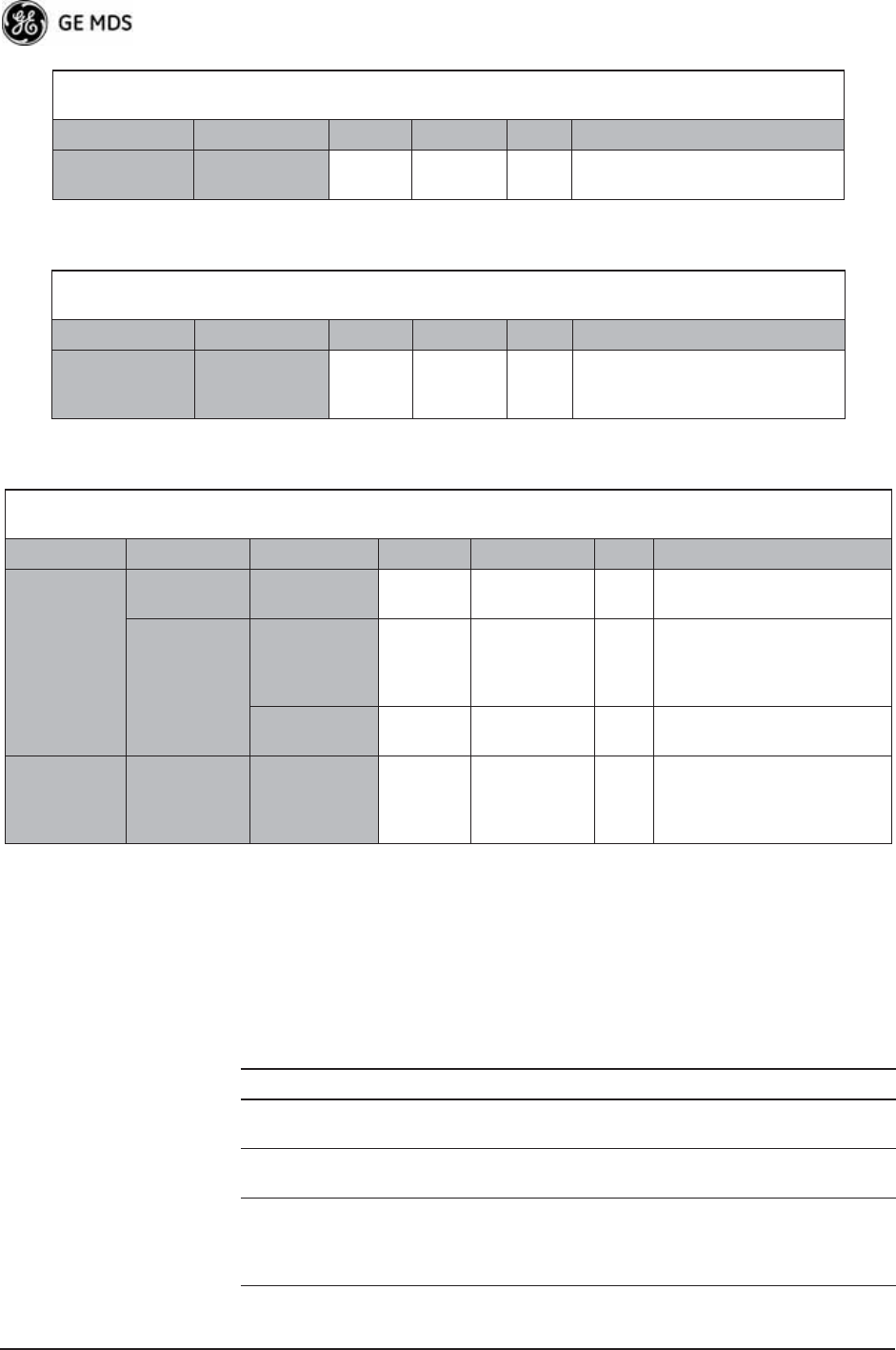
Table 3-12 and Table 3-13 on Page 143 show target performance values
for AP and Remote transceivers. View these values using the built-in
menu system by navigating the path shown under each table title.
For Optimal Sensitivity
(Trades off throughput for best possible sensitivity. AP more susceptible to interference)
AP Remote Units Notes
Radio
Configuration
Receive
Power
-80 N/A dBm Sets AP receiver for highest gain.
When Heavy Interference Exists at AP
(Trades off range for robustness in the face of interference)
AP Remote Units Notes
Radio
Configuration
Receive
Power
-60 N/A dBm Sets AP receiver for low gain,
which forces Remote transmit
power to be high.
For Mobile Systems
(Where hand-offs between APs are required)
AP Remote Units Notes
Radio
Configuration
Frequency
Control
Frequency
Mode
Static
Hopping
Hopping
w/Hand-offs
Advanced
Configuration
Protection
Margin
66dBMore channel variation in
mobile, so use more robust
modulation with greater
SNRs.
Channel Type Dynamic N/A Less periodic ranging when
Channel Type = Static.
Network
Configuration
AP Location
Info Config
Retrieve Text
File
N/A AP
Locations file
AP locations file with
coordinates and key
attributes of APs to which
Remote can associate.
Table 3-12. Mercury Remote Transceiver
(Performance Information>>Internal Radio Status Menu)
Name Target Value Notes
Connection Status Associated Remote must be associated
for network operation.
Transmit Power Varies Adjusts automatically as
requested by AP.
RSSI
(Received Signal
Strength Indication)
Varies The less negative an RSSI
reading, the stronger the
signal (i.e., -75 dBm is
stronger than -85 dBm).

05-4446A01, Rev. D Mercury Reference Manual 143
Additional Considerations for Mobile Operation
Consider the following key points for all mobile installations:
SNR
(Signal-to-Noise Ratio)
Strong signal (bench
setting): 25-28 dB
Operational: 3-30 dB
Typ. System: 10-20 dB
A low SNR may be caused by
noise or interfering signals.
TX Freq. Offset 0-22,875 Hz Adjusts to accommodate what
is expected by the AP.
RX Freq. Offset 0-22,875 Hz Adjusts to accommodate what
is expected by the AP.
Total FEC Count Varies
Corrected FEC Count Varies
Uncorrected FEC
Count
Varies
Current AP Name Device name of
associated AP
Typically set to reflect the
application or system the radio
is used in.
Table 3-12. Mercury Remote Transceiver (Continued)
(Performance Information>>Internal Radio Status Menu)
Name Target Value Notes
Table 3-13. Mercury Access Point
(Performance Information>>Wireless Network Status>>
Remote Performance Database)
Name Target Value Notes
MAC ADDR MAC Address of
associated Remote
Must match Remote’s MAC
address exactly
RSSI
(Received Signal
Strength Indication)
Varies The less negative an RSSI
reading, the stronger the
signal (i.e., -75 dBm is
stronger than -85 dBm).
SNR
Signal-to-Noise Ratio
Strong signal (bench):
25-28 dB
Operational: 3-30 dB
Typ. System:10-20 dB
A low SNR may be caused by
noise or interfering signals.
Downlink Varies QPSK/FEC-3/4 Preferred
Uplink Varies QPSK/FEC-3/4 Preferred
FEC Total Varies
Corrected FEC Count Varies
Uncorrected FEC
Count
Varies

144 Mercury Reference Manual 05-4446A01, Rev. D
• Use connectionware—The use of connectionware in the mobile lap-
tops is highly recommended for better operation of a mobile data
system. GE MDS provides connectionware from one of the vendors
in this market. Contact your factory representative for details.
• Plan your network coverage—Deploy Access Points so that they
provide overlapping coverage with each other. Access Points must
use the same Network Name to enable roaming service.
• Set the RSSI Threshold to -70 dBm—This level is typically used for
mobile systems with good performance. Make sure there is overlap-
ping coverage of more than one AP to provide continuous coverage.
• At every AP Radio, review the following settings when providing
service to mobile remotes:
•TDD Sync—Set to GPS Required.
•Pattern Offset—Each AP should be different. Cell planning is
required if there are overlaps.
•Hop Pattern—Set the same on all APs.
•Compression [disabled]—Disable radio compression. Data com-
pression is best performed by the connectionware running on
the mobile laptop PC. Gains in efficiency are made because
connectionware compresses data at a higher stack level, and it
aggregates multiple data frames and streams into a single
packet. Compression at the radio level, although highly effi-
cient, works only at the individual packet level.

05-4446A01, Rev. D Mercury Reference Manual 145
4 TROUBLESHOOTING &
RADIO MEASUREMENTS
4 Chapter Counter Reset Paragraph
Contents
4.1 TROUBLESHOOTING........................................................... 147
4.1.1 Interpreting the Front Panel LEDs ......................................... 147
4.1.2 Troubleshooting with the Embedded Management Sys. ........ 148
4.1.3 Using Logged Operation Events ............................................ 151
4.1.4 Alarm Conditions .................................................................... 152
4.1.5 Correcting Alarm Conditions .................................................. 153
4.1.6 Logged Events ....................................................................... 153
4.2 RADIO (RF) MEASUREMENTS............................................ 155
4.2.1 Antenna System SWR and Transmitter Power Output .......... 155
4.2.2 Antenna AimingFor Directional Antennas ........................... 156

146 Mercury Reference Manual 05-4446A01, Rev. D

05-4446A01, Rev. D Mercury Reference Manual 147
4.1 TROUBLESHOOTING
Successful troubleshooting of a wireless system is not difficult, but
requires a logical approach. It is best to begin troubleshooting at the
Access Point unit, as the rest of the system depends on the Access Point
for synchronization data. If the Access Point has problems, the operation
of the entire wireless network is affected.
When you find communication problems, it is good practice to begin by
checking the simple causes. Applying basic troubleshooting techniques
in a logical progression identifies many problems.
Multiple
Communication
Layers
It is important to remember that the operation of the network is built on
a radio communications link. On top of that are two data levels— wire-
less MAC, and the data layer. It is essential that the wireless aspect of
the Access Point and the Remotes units to be associated operates prop-
erly before data-layer traffic will function.
Unit Configuration There are numerous user-configurable parameters in the Management
System. Do not overlook the possibility that human error is the cause of
the problem. With so many parameters to view and change, a parameter
might be incorrectly set, and then that change is forgotten.
To help avoid these problems, GE MDS recommends creating an
archive of the transceiver’s profile in a Configuration File when your
installation is complete. You can reload this file into the transceiver to
restore the unit to the factory defaults or your unique profile. For details
on creating and archiving Configuration Files, see “Configuration
Scripts Menu” on Page 130.
Factory Assistance If problems cannot be resolved using the guidance provided here,
review the GE MDS web site’s technical support area for recent soft-
ware/firmware updates, general troubleshooting help, and service infor-
mation. Additional help is available through our Technical Support
Department. (See “TECHNICAL ASSISTANCE” on the inside of the
rear cover.)
4.1.1 Interpreting the Front Panel LEDs
An important set of troubleshooting tools are the LED status indicators
on the front panel of the radio case. You should check them first when-
ever a problem is suspected. Table 2-2 on Page 30 describes the func-
tion of each status LED. Table 4-1 on Page 148 provides suggestions for

148 Mercury Reference Manual 05-4446A01, Rev. D
resolving common system difficulties using the LEDs, and Table 4-2 on
Page 149 provides other simple techniques.
4.1.2 Troubleshooting With the Embedded
Management System
If you have reviewed and tried the items listed in Table 4-1 and still have
not resolved the problem, there are additional tools and techniques you
can use. The embedded Management System is a good source of infor-
mation that you can use remotely to provide preliminary diagnostic
information, or may even provide a path to correcting the problem.
Refer to Table 4-2 on Page 149 for more information on using the Man-
agement System as a troubleshooting tool.
Table 4-1. Troubleshooting Using LEDs—Symptom-Based
Symptom Problem/Recommended System Checks
PWR LED does not
turn on
a. Voltage too low—Check for the proper supply voltage at
the power connector. (10–30 Vdc)
b. Indefinite Problem—Cycle the power and wait
(≈ 30 seconds) for the unit to reboot. Then, recheck for
normal operation.
LINK LED does not
turn on
a. Network Name of Remote not identical to desired Access
Point—Verify that the system has a unique Network Name.
b. Not yet associated with an Access Point with the same
Network Name.
Check the “Status” of the unit’s process of associating with
the Access Point. Use the Management System.
c. Poor Antenna System—Check the antenna, feedline and
connectors. Reflected power should be less than 10% of
the forward power reading (SWR 2:1 or lower).
PWR LED is
blinking
a. Blinking indicates that an alarm condition exists.
b. View Current Alarms and Event Log and correct the
problem if possible.
(See “Using Logged Operation Events” on Page 151)
c. Blinking continues until the source of the alarm is
corrected, for example, a valid IP address is entered, etc.
LAN LED does not
turn on
a. Verify the Ethernet cable is connect at both ends.
b. Verify that the appropriate type of Ethernet cable is used:
straight-through or crossover.
LAN LED lights, but
turns off after some
time
Verify traffic in LAN. Typically, the radio should not be placed
in high traffic enterprise LANs, as it will not pass this level of
traffic. If needed, use routers to filter traffic.
GPS LED not lit No satellite fix has been obtained. A fix is required for all
operation except single-frequency channel (non-hopping)
configurations. The lack of a fix may be caused by an
obstructed “view” of the satellites, or a GPS antenna problem.
The GPS LED blinks slowly on the AP while it synchronizes its
internal clock to the GPS signal. When in this condition, the AP
does not transmit.

05-4446A01, Rev. D Mercury Reference Manual 149
The following is a summary of how you can use several screens in the
Management System as diagnostic tools. For information on how to
Table 4-2. Basic Troubleshooting Using the Management System
Symptom Problem/Recommended System Checks
Cannot access the
MS through COM1
a. Connect to unit via Telnet or Web browser.
b. Disable the serial mode for COM1
(Serial Gateway Configuration>>Com1 Serial Data
Port>>Status>>Disabled).
Or, if you know the unit’s data configuration:
a. Connect to COM 1 via a terminal set to VT100 and the
port’s data baud rate.
b. Type +++.
c. Change the terminal’s baud rate to match the transceiver’s
Console Baud Rate.
d. Type +++.
Display on
terminal/Telnet
screen garbled
Verify the terminal/terminal emulator or Telnet application is
set to VT100.
Password forgotten a. Connect to the transceiver using a terminal through the
COM1 Port.
b. Obtain a password-resetting Authorization Key from your
factory representative.
c. At the login prompt, try the user name authcode, and enter
the Authorization Key for the password.
Remote only gets
to Connecting
a. Check Network Name, encryption, and Device Auth Mode
settings.
b. Verify that the correct MAC address is listed in the
Approved Remotes List of the Security Configuration
Menu.
Remote only gets
to Authenticating
Check encryption settings and security mode settings.
Cannot pass IP
data to WAN
a. Verify your IP settings.
b. Use the PING command to test communication with the
transceivers in the local radio system.
c. If successful with local PING, attempt to PING an IP unit
attached to a transceiver.
d. If successful with the LAN PINGs, try connecting to a
known good unit in the WAN.
Wireless Retries
too high
Possible Radio Frequency Interference:
a. If omnidirectional antennas are used, consider changing to
directional antennas. This usually limits interference to and
from other stations.
b. Try disabling channels where persistent interference is
known or suspected.
c. The installation of a filter in the antenna feedline may be
necessary. Consult the factory for further assistance.
d. Try using an antenna with a downward tilt.

150 Mercury Reference Manual 05-4446A01, Rev. D
connect to the Management System, see “STEP 3—CONNECT PC TO
THE TRANSCEIVER” on Page 25.
Starting Information Screen
(See Starting Information Screen on Page 42)
The Management System’s home page provides some valuable bits of
data. One of the most important is the Device Status field. This item tells
you if the unit is operational.
If the Device Status field says Associated, then look in the network areas
beginning with network data statistics. If it displays some other mes-
sage, such as Scanning, Connecting, or Alarmed, you must determine why
it is in this state.
The Scanning state indicates a Remote unit is looking for an Access
Point beacon signal to lock onto. It should move to the Connecting state
and finally to the Associated state within less than a minute. If this
Remote unit is not providing reliable service, look at the Event Logs for
signs of lost association with the Access Point, or low signal alarms.
Table 4-3 provides a description of the Device Status messages.
If the Remote is in an Alarmed state, the unit might still be operational
and associated. Look for the association state in the Wireless Network
Status screen to determine if the unit is associated. If it is, look at the
Error Log for possible clues.
If the unit is in an Alarmed state and is not associated with an Access
Point, then there might be a problem with the wireless network layer.
Call a radio technician to deal with wireless issues. Refer the technician
to the RADIO (RF) MEASUREMENTS on Page 155 for information on
antenna system checks.
Table 4-3. Device Status1
1. Device Status is available in the Startup Information Screen or the Wireless Status
Screen at Remotes.
Scanning The unit is looking for an Access Point beacon signal.
Ranging Remote has detected AP and is synchronizing to it.
Connecting The Remote has established a radio (RF) connection
with the Access Point and is negotiating the network
layer connectivity.
Authenticating2
2. If Device Authentication is enabled.
The Remote is authenticating itself to the network to
obtain cyber-security clearance in order to pass data.
Associated This unit has successfully synchronized and is
“associated” with an Access Point. This is the normal
operating state.
Alarmed The unit has detected one or more alarms that have not
been cleared.

05-4446A01, Rev. D Mercury Reference Manual 151
Packet Statistics Menu
(See Packet Statistics Menu on Page 113)
This screen provides detailed information on data exchanges between
the unit being viewed and the network through the wireless and the
Ethernet (data) layers. These include:
The most significant fields are the Packets Dropped, Retries, Retry
Errors, Receive Errors and Lost Carrier Detected. If the data values are
more than 10% of their sent and received counterparts, or the Lost Car-
rier Detected value is greater than a few dozen, there might be trouble
with radio-frequency interference or a radio link of marginal strength.
If errors are excessive, check the aiming of the antenna system, and
check for a satisfactory SWR. Refer to RADIO (RF) MEASUREMENTS
on Page 155 for information on antenna system checks.
Diagnostic Tools
(See MAINTENANCE/TOOLS MENU on Page 122)
The radio’s Maintenance menu contains two tools that are especially
useful to network technicians—the Radio Test Menu and the Ping
Utility. Use the Radio Test selection for testing RF operation. Use the
Ping Utility to verify communications access to pieces of equipment
connected to the radio network. This includes transceivers and user-sup-
plied Ethernet devices.
4.1.3 Using Logged Operation Events
(See PERFORMANCE INFORMATION MENU on Page 109)
The transceiver’s microprocessor monitors many operational parame-
ters and logs them as various classes of events. If the event is one that
affects performance, it is an alarm. There are also normal or routine
events such as those marking the rebooting of the system, implementa-
tion of parameter changes, and external access to the Management
System. Informational events are stored in temporary (RAM) memory
that is lost in the absence of primary power, and Alarms are stored in
Wireless Packet Statistics
• Packets received • Packets dropped
• Packets sent • Receive errors
• Bytes received • Retries
• Bytes sent • Retry errors
Ethernet Packet Statistics
• Packets received • Packets dropped
• Packets sent • Receive errors
• Bytes received • Retries
• Bytes sent • Retry errors
• Lost carrier detected

152 Mercury Reference Manual 05-4446A01, Rev. D
permanent memory (Flash memory) until cleared by user request.
Table 4-4 summarizes these classifications.
These events are stored in the transceiver’s Event Log and can be a valu-
able aid in troubleshooting unit problems or detecting attempts at
breaching network security.
4.1.4 Alarm Conditions
Most events, classified as “critical” will cause the PWR LED to blink,
and will inhibit normal operation of the transceiver. The LED blinks
until the corrective action is completed. (See also Event Log Menu on
Page 112.)
Table 4-4. Event Classifications
Level Description/Impact Storage
Alarms Transceiver has detected one or
more alarm conditions
Flash
Memory
Informational Normal operating activities Flash
Memory
Temporary
Informational
Transient conditions or events RAM
Minor Does not affect unit operation RAM
Major Degraded unit performance but
still capable of operation
RAM
Critical Prevents the unit from operating RAM
Table 4-5. Alarm Conditions (Alphabetical Order)
Alarm Condition Reported Event Log Entry SNMP Trap
EVENT_BRIDGE Network Interface /Error networkInterface(17)
EVENT_FREQ_CAL Frequency Not
Calibrated
frequencyCal(7)
EVENT_INIT_ERR Initialization Error initializationError(18)
EVENT_IPADDR*IP Address Invalid ipAddressNotSet(4)
EVENT_IPMASK*IP Mask Invalid ipNetmaskNotSet(5)
EVENT_LAN_PORT lanPortStatus(78)
EVENT_MAC MAC communication
Failed
macCommunication(1)
EVENT_MACADDR MAC Address Invalid noMacAddress(6)
EVENT_NETNAME*Netname Invalid invalidNetname(12)
EVENT_POWER_CAL Power Calibrated/Not
Calibrated
powerCal(8)
EVENT_REMOTE Remote Added/
Removed (AP Only)
eventRemote(66)
EVENT_RSSI*RSSI Exceeds
threshold
rssi(11)

05-4446A01, Rev. D Mercury Reference Manual 153
* User can correct condition, clearing the alarm.
4.1.5 Correcting Alarm Conditions
(See Event Log Menu on Page 112)
Table 4-6 provides likely causes of events that inhibit the unit from
operating, and possible corrective actions. The Event Description
column appears on the Event Log screen.
4.1.6 Logged Events
The following events allow the transceiver to continue operation and do
not make the PWR LED blink. Each is reported through an SNMP trap.
EVENT_RSSI_CAL RSSI Not Calibrated rssiCal(9)
EVENT_SYSTEM_ERROR* System Error Cleared;
Please Reboot
systemError(16)
EVENT_TFTP_CONN TFTP connectivity
achieved
tftpConnection(73)
EVENT_TFTP_ERR Attempted TFTP
connection failed
tftpConnFailed(79)
Table 4-5. Alarm Conditions (Alphabetical Order) (Continued)
Alarm Condition Reported Event Log Entry SNMP Trap
Table 4-6. Correcting Alarm Conditions—Alphabetical Order
Event Log Entry Generating Condition Clearing Condition
or Action
Bridge Down The Bridge fails to be
initialized.
Contact factory Technical
Services for assistance.
General System
Error
Internal checks suggest unit
is not functioning properly.
Reboot the transceiver.
Initialization Error Unit fails to complete boot
cycle.
Contact factory Technical
Services for assistance.
Invalid IP Address The IP address is either
0.0.0.0 or 127.0.0.1.
Program IP address to
something other than 0.0.0.0
or 127.0.0.1.
Network Interface
Error
Unit does not recognize the
LAN interface.
Contact factory Technical
Services for assistance.
RSSI Exceeds
Threshold
The running-average RSSI
level is weaker (more
negative) than the
user-defined value.
Check the aiming of the
directional antenna at the
Remote; raise the threshold
level to a stronger
(less-negative) value.

154 Mercury Reference Manual 05-4446A01, Rev. D
The left hand column, Event Log Entry, is what shows in the Event Log.
(See also Event Log Menu on Page 112.)
Table 4-7. Non-Critical Events—Alphabetical Order
Event Log Entry Severity Description
Association Attempt
Success/Failed
MAJOR Self explanatory
Association Lost - Local IP
Address Changed
MAJOR Self explanatory
Association Lost - Local
Network Name Changed
MAJOR Self explanatory
Association Lost/Established MAJOR Self explanatory
Auth Demo Mode Expired --
Rebooted Radio/Enabled
MAJOR Self explanatory
Auth Key Entered - Key
Valid/Key Invalid
MAJOR Self explanatory
Console Access Locked for
5 Min
MAJOR Self explanatory
Console User Logged
Out/Logged In
MAJOR Self explanatory
Current AP No Longer
Approved
MAJOR May occur during the Scanning
process at a Remote. Indicates
that the received beacon came
from an AP which is not in the
“Approved AP” list. This might be
caused by some Remotes hearing
multiple AP's. This event is
expected behavior.
Decryption Error/Decryption
OK
MAJOR A decryption error is logged when
an encryption phrase mismatch
has occurred. A mismatch is
declared after five consecutive
errors over a 40-second window.
When the error has cleared,
DECRYPT OK appears.
Ethernet Port
Enabled/Disabled
INFORM Self explanatory
Ranging Lost/Established INFORM Self explanatory
Connecting Lost/Established INFORM Self explanatory
HTTP Access Locked for 5 Min MAJOR Self explanatory
HTTP User Logged
Out/Logged In
MAJOR httpLogin(49)
Log Cleared INFORM Self explanatory
Reprogramming Complete INFORM Self explanatory
Reprogramming Failed MAJOR Self explanatory
Reprogramming Started INFORM Self explanatory
Scanning Started INFORM Self explanatory
SNR Within threshold/Below
threshold
INFORM Self explanatory

05-4446A01, Rev. D Mercury Reference Manual 155
4.2 RADIO (RF) MEASUREMENTS
There are several measurements that should be performed during the ini-
tial installation. These measurements confirm proper operation of the
unit and, if they are recorded, serve as a benchmark in troubleshooting
should difficulties appear in the future. These measurements are:
• Transmitter Power Output
• Antenna System SWR (Standing-Wave Ratio)
• Antenna Direction Optimization
These procedures might interrupt traffic through an established network
and should only be performed by a skilled radio-technician in coopera-
tion with the Network Administrator.
4.2.1 Antenna System SWR and Transmitter Power
Output
Introduction
A proper impedance match between the transceiver and the antenna
system is important. It ensures the maximum signal transfer between the
radio and antenna. You can check the impedance match indirectly by
measuring the SWR (standing-wave ratio) of the antenna system. If the
results are normal, record them for comparison during future routine
preventive maintenance. Abnormal readings indicate possible trouble
with the antenna or the transmission line, and should be corrected.
Check the SWR of the antenna system before putting the radio into reg-
ular service. For accurate readings, a wattmeter suited to the frequency
of operation is required. One unit meeting this criteria is the Bird Model
43™ directional wattmeter with the appropriate element installed.
The reflected power should be less than 10% of the forward power
(≈2:1 SWR). Higher readings indicate problems with the antenna, feed-
line or coaxial connectors.
Record the current transmitter power output level, then set it to an ade-
quate signal level for the directional wattmeter (for the duration of the
test.)
System Bootup (power on) INFORM Self explanatory
Telnet Access Locked for
5 Min
MAJOR Self explanatory
Telnet User Logged
Out/Logged In
MAJOR Self explanatory
User Selected Reboot MAJOR Self explanatory
Table 4-7. Non-Critical Events—Alphabetical Order (Continued)
Event Log Entry Severity Description

156 Mercury Reference Manual 05-4446A01, Rev. D
Procedure
1. Place a directional wattmeter between the TX antenna connector and
the antenna system.
2. Place the transceiver into the Radio Test Mode using the menu
sequence below:
(Maintenance/Tools Menu>>Radio Test>>Radio Mode>>Test)
3. Set the transmit power to 29 dBm (900 model), or 23 dBm (3650
model). (This setting does not affect the output level during normal
operation—only during Test Mode.)
(Maintenance/Tools Menu>>Radio Test >>Test Mode>>Test>>Test Transmit
Power)
4. Key the transmitter.
(Maintenance/Tools Menu>>Radio Test>>Test Mode>>Test>>Test Key>>
enabled)
Use the PC’s spacebar to key and unkey the transmitter.
(Enable/Disable)
NOTE: The Transmit Key has a 10-minute timer, after which it unkeys
the radio. Manually unkey the transmitter by selecting Test
Key>>disabled on the menu, or temporarily disconnecting the
radio’s DC power.
5. Measure the forward and reflected power into the antenna system
and calculate the SWR and power output level. The output should
agree with the programmed value set in the Radio Configuration
Menu. (Radio Configuration>>Transmit Power)
6. Turn off Radio Test Mode.
(Maintenance/Tools Menu>>Radio Test>>Test Key>>disabled)
End of procedure.
4.2.2 Antenna Aiming—For Directional Antennas
Introduction
The radio network integrity depends, in a large part, on stable radio
signal levels at each end of a data link. In general, signal levels stronger
than –80 dBm provide the basis for reliable communication that
includes a 15 dB fade margin. As the distance between the Access Point
and Remotes increases, the influence of terrain, foliage, and man-made
obstructions become more influential, and the use of directional
antennas at Remote locations becomes necessary. Directional antennas
require fine-tuning of their bearing to optimize the received signal
strength. The transceiver has a built-in received signal strength indicator
(RSSI) that can tell you when the antenna is in a position that provides
the optimum received signal.

05-4446A01, Rev. D Mercury Reference Manual 157
RSSI measurements and Wireless Packet Statistics are based on mul-
tiple samples over a period of several seconds. The average of these
measurements is displayed by the Management System.
The measurement and antenna alignment process usually takes 10 or
more minutes at each radio unit.
The path to the Management System menu item is shown in bold text
below each step of the procedure.
Procedure
1. Verify the Remote transceiver is associated with an Access Point
unit by observing the condition of the LINK LED (LINK LED = On or
Blinking). This indicates that you have an adequate signal level for
the measurements and it is safe to proceed.
2. Record the Wireless Packets Dropped and Received Error rates.
(Main Menu>>Performance Information>>Packet Statistics>>Wireless Packet
Statistics)
This information will be used later.
3. Clear the Wireless Packets Statistics history.
(Main Menu>>Performance Information>>Packet Statistics>>Wireless Packet
Statistics>>Clear Wireless Stats)
4. Read the RSSI level at the Remote.
(Main Menu>>Performance Information>>Internal Radio Status)
5. Optimize RSSI (less negative is better) by slowly adjusting the
direction of the antenna.
Watch the RSSI indication for several seconds after making each
adjustment so that the RSSI accurately reflects any change in the
link signal strength.
6. View the Wireless Packets Dropped and Received Error rates at the
point of maximum RSSI level. They should be the same or lower
than the previous reading.
(Main Menu>>Performance Information>>Packet Statistics>>Wireless Packet
Statistics)

158 Mercury Reference Manual 05-4446A01, Rev. D
7. If the RSSI peak results in an increase in the Wireless Packets
Dropped and Received Error, the antenna may be aimed at an undes-
ired signal source. Try a different antenna orientation.
End of procedure.

05-4446A01, Rev. D Mercury Reference Manual 159
5PLANNING A RADIO
NETWORK
5 Chapter Counter Reset Paragraph
Contents
5.1 INSTALLATION PLANNING .................................................. 161
5.1.1 General Requirements ........................................................... 161
5.1.2 Site Selection ......................................................................... 162
5.1.3 Terrain and Signal Strength .................................................... 163
5.1.4 Antenna & Feedline Selection ................................................ 163
5.1.5 How Much Output Power Can be Used? ............................... 167
5.1.6 Conducting a Site Survey ...................................................... 167
5.1.7 A Word About Radio Interference ........................................... 168
5.1.8 ERP Compliance at 900 MHz ................................................ 170
5.1.9 ERP Compliance at 3650 MHz .............................................. 171
5.2 dBm-WATTS-VOLTS CONVERSION CHART....................... 172

160 Mercury Reference Manual 05-4446A01, Rev. D
05-4446A01, Rev. D Mercury Reference Manual 161
5.1 INSTALLATION PLANNING
This section provides tips for selecting an appropriate site, choosing an
antenna system, and reducing the chance of harmful interference.
5.1.1 General Requirements
There are three main requirements for installing a transceiver—ade-
quate and stable primary power, a good antenna system, and the correct
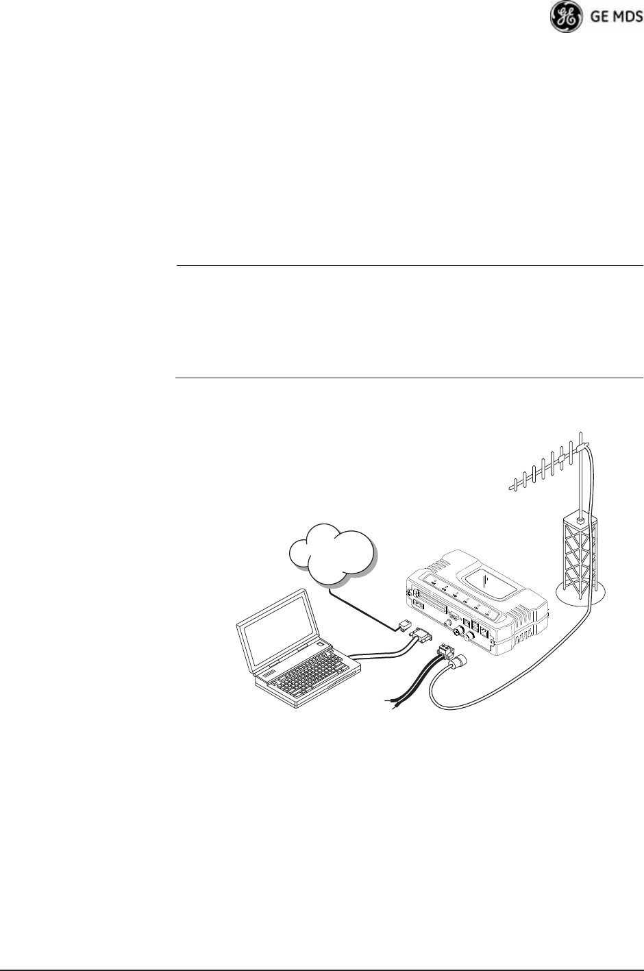
interface between the transceiver and the data device. Figure 5-1 shows
a typical Remote installation.
NOTE: The transceiver’s network port supports 10BaseT and
100BaseT connections. Confirm that your hub/switch is
capable of auto-switching data rates.
To prevent excessive Ethernet traffic from degrading perfor-
mance, place the transceiver in a segment, or behind routers.
Invisible place holder
Figure 5-1. Typical Fixed Remote Installation
With a Directional Antenna
(Connect user data equipment to any compatible LAN Port)
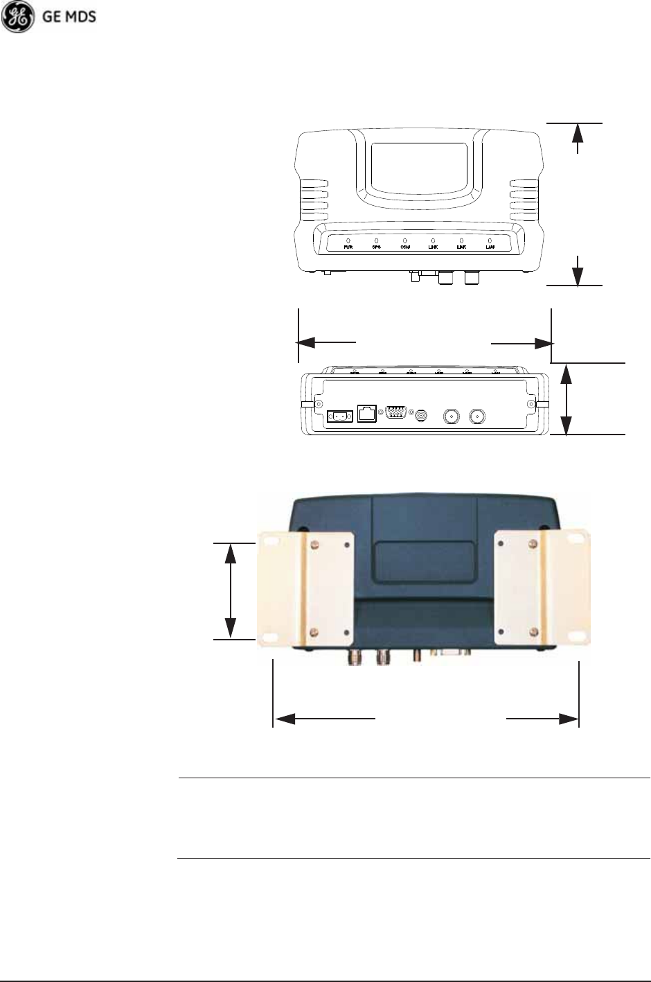
Unit Dimensions
Figure 5-2 on Page 162 shows the dimensions of the transceiver case
and its mounting holes, and Figure 5-3 on Page 162 shows the dimen-
sions for mounting with factory-supplied brackets. If possible, choose a
POWER SUPPLY
13.8 VDC @ 580 mA (Max.)
(10.5–30 Vdc)
Negative Ground Only
COMPUTER RUNNING
TERMINAL PROGRAM
TRANSCEIVER
LOW-LOSS FEEDLINE
ANTENNA
SYSTEM
Network
162 Mercury Reference Manual 05-4446A01, Rev. D
mounting location that provides easy access to the connectors on the end
of the radio and an unobstructed view of the LED status indicators.
Figure 5-2. Transceiver Dimensions
Invisible place holder
Invisible place holder
Figure 5-3. Mounting Bracket Dimensions (center to center)
NOTE: To prevent moisture from entering the radio, do not mount the
radio with the cable connectors pointing up. Also, dress all
cables to prevent moisture from running along the cables and
into the radio.
5.1.2 Site Selection
Suitable sites should provide:
• Protection from direct weather exposure
1.4
6.75 (17.15 cm)
4.5 (11.43 cm)
TOP
FRONT (3.56 cm)
VIEW
VIEW
2.75 (7 cm)
8 5/8 (21.8 cm)

05-4446A01, Rev. D Mercury Reference Manual 163
• A source of adequate and stable primary power
• Suitable entrances for antenna, interface, or other required
cabling
• An antenna location that provides a transmission path that is as
unobstructed as possible in the direction of the associated sta-
tion(s)
With the exception of the transmission path, you can quickly determine
these requirements. Radio signals travel primarily by line-of-sight, and
obstructions between the sending and receiving stations will affect
system performance. If you are not familiar with the effects of terrain
and other obstructions on radio transmission, the discussion below will
provide helpful background.
5.1.3 Terrain and Signal Strength
While the license-free bands offers many advantages for data transmis-
sion services, signal propagation is attenuated by obstructions such as
terrain, foliage, or buildings in the transmission path. A line-of-sight
transmission path between the central transceiver and its associated
remote site(s) is highly desirable and provides the most reliable commu-
nications link.
Much depends on the minimum signal strength that can be tolerated in
a given system. Although the exact figure will differ from one system to
another, a Received Signal Strength Indication (RSSI) of –80 dBm or
stronger will provide acceptable performance in most systems. While
the equipment will work at lower-strength signals, signals stronger than
– 77 dBm provide a fade margin of 15 dB to account for variations in
signal strength that might occur. You can measure RSSI with a terminal
connected to the COM1 port, or with an HTTP browser connected to the
LAN (Ethernet) connector. (See “Antenna Aiming—For Directional
Antennas” on Page 156 for details.)
5.1.4 Antenna & Feedline Selection
NOTE: The transceiver must be installed by trained professional
installers, or factory trained technicians.
The following text will help the professional installer in the
proper methods of maintaining compliance with regulatory
ERP limits.
Antennas
The radio equipment can be installed with a number of antennas. The
exact style used depends on the physical size and layout of a system.
Contact your factory representative for specific recommendations on
antenna types and hardware sources.
164 Mercury Reference Manual 05-4446A01, Rev. D
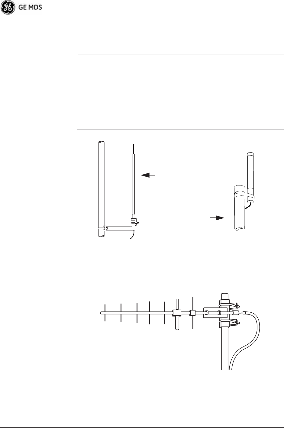
In general, an omnidirectional antenna (Figure 5-4) is used at the Access
Points and mobile Remote stations. This provides equal signal coverage
in all directions.
NOTE: Antenna polarization is important. If the wrong polarization is
used, a signal reduction of 20 dB or more will result. Most
systems using a gain-type omnidirectional antenna at Access
Point stations employ vertical polarization of the signal; there-
fore, the Remote antenna(s) must also be vertically polarized
(elements oriented perpendicular to the horizon).
When required, horizontally polarized omnidirectional
antennas are also available. Contact your factory representa-
tive for details.
Invisible place holder
Figure 5-4. Typical Omnidirectional Antennas
At fixed Remote sites, a directional Yagi antenna (Figure 5-5 on
Page 164) minimizes interference to and from other users. Antennas are
available from a number of manufacturers.
Invisible place holder
Figure 5-5. Typical Yagi Antenna (mounted to mast)
High-gain Type
Unity-gain Type

05-4446A01, Rev. D Mercury Reference Manual 165
Diversity Reception (RX2) Antenna Port
Functional on some models. The RX2 antenna port allows connection of
a second antenna to the transceiver for space diversity reception.
GPS Antennas
A number of GPS antennas (both active and passive) are available for
use with the transceivers. Consult your factory representative for more
information.
Feedlines
Carefully consider the choice of feedline used with the antenna. Avoid
poor-quality coaxial cables, as they degrade system performance for
both transmission and reception. A low-loss cable type such as Heliax®
is recommended that is suitable for the frequency of operation. Keep the
cable as short as possible to minimize signal loss.
Table 5-1 lists several types of popular feedlines and indicates the signal
losses (in dB) that result when using various lengths of cable at
900 MHz. The choice of cable depends on the required length, cost con-
siderations, and the acceptable amount of signal loss. Table 5-1 lists
several types of popular feedlines and indicates the signal losses (in dB)
that result when using various lengths of cable at 900 MHz. The choice
of cable depends on the required length, cost considerations, and the
acceptable amount of signal loss.
Table 5-1. Length vs. Loss in Coaxial Cables at 900 MHz
Cable Type
10 Feet
(3.05 m)
50 Feet
(15.24 m)
100 Feet
(30.48 m)
500 Feet
(152.4 m)
RG-214 .76 dB 3.8 dB 7.6 dB Unacceptable
Loss
LMR-400 0.39 dB 1.95 dB 3.90 dB Unacceptable
Loss
1/2 inch HELIAX 0.23 dB 1.15 dB 2.29 dB 11.45 dB
7/8 inch HELIAX 0.13 dB 0.64 dB 1.28 dB 6.40 dB
1-1/4 inch HELIAX 0.10 dB 0.48 dB 0.95 dB 4.75 dB
1-5/8 inch HELIAX 0.08 dB 0.40 dB 0.80 dB 4.00 dB
Table 5-2. Length vs. Loss in Coaxial Cables at 3600 MHz
Cable Type
10 Feet
(3.05 m)
50 Feet
(15.24 m)
100 Feet
(30.48 m)
500 Feet
(152.4 m)
RG-214 3.04 dB 15.2 dB Unacceptable
Loss
Unacceptable Loss
LMR-400 1.56 dB 7.8 dB 15.6 dB Unacceptable Loss

166 Mercury Reference Manual 05-4446A01, Rev. D
The tables below outline the minimum lengths of RG-214 coaxial cable
that must be used with common GE MDS omnidirectional antennas in
order to maintain compliance with FCC maximum limit of +36 dBi. If
other coaxial cable is used, make the appropriate changes in loss figures.
NOTE: The authority to operate the transceiver in the USA may be
void if antennas other than those approved by the FCC are
used. Contact your factory representative for additional
antenna information.
*Refer to Table 5-4 on Page 170 for allowable transceiver power set-
tings for each antenna type.
1/2 inch HELIAX 0.92 dB 4.6 dB 9.16 dB Unacceptable Loss
7/8 inch HELIAX 0.52 dB 2.56 dB 5.12 dB Unacceptable Loss
1-1/4 inch HELIAX 0.40 dB 1.92 dB 3.8 dB 19 dB
1-5/8 inch HELIAX 0.32 dB 1.6 dB 3.2 dB 16 dB
Table 5-2. Length vs. Loss in Coaxial Cables at 3600 MHz
Cable Type
10 Feet
(3.05 m)
50 Feet
(15.24 m)
100 Feet
(30.48 m)
500 Feet
(152.4 m)
Table 5-3. Feedline Length vs. Antenna Gain*
(Required for Regulatory Compliance)
Antenna
Gain (dBd)
Antenna
Gain (dBi)
Minimum Feedline
Loss (dB) that must
be introduced for
compliance
EIRP Level @
Min. Feedline
Length
Maxrad Antenna
Part No. (For 900
MHz Operation)
Unity (0 dB) 2.15 dBi No minimum length +32.15 dBm Omni #MFB900
3 dBd 5.15 dBi No minimum length +35.15 dBm Omni # MFB900
5 dBd 7.15 dBi 1.2 dB +35.95 dBm Omni # MFB900
6 dBd 8.15 dBi 2.2 dB +35.95 dBm Yagi # BMOY8903
9 dBd 11.15 dBi 7.15 dB +35.25 dBm Yagi # Z941
15.2 dBd 17.4 dBi 12 dB +35.4 dBm Andrew
DB878G90A-XY

05-4446A01, Rev. D Mercury Reference Manual 167
NOTE: There is no minimum feedline length required when a 6 dBi
gain or less antenna is used, as the EIRP will never exceed
36 dBm which is the maximum allowed, per FCC rules. Only
the manufacturer or a sub-contracted professional installer can
adjust the transceiver’s RF output power.
The transceiver’s power output is factory set to maintain
compliance with the FCC’s Digital Transmission System
(DTS) Part 15 rules. These rules limit power to a maximum of
8 dBm/3 kHz, thus the transceiver is factory set to +29 dBm
(900 model); 23 dBm (3650 model). When calculating
maximum transceiver power output, use +29 dBm if the
antenna gain is 6 dBi or less (36 dBm ERP). See How Much
Output Power Can be Used? below for power control of higher
gain antennas.
5.1.5 How Much Output Power Can be Used?
The transceiver is normally configured at the factory for a nominal RF
power output of +29 dBm (900 model); +23 dBm (3650 model) this is
the maximum transmitter output power allowed under FCC rules. The
power must be decreased from this level if the antenna system gain
exceeds 6 dBi. The allowable level is dependent on the antenna gain,
feedline loss, and the transmitter output power setting.
NOTE: In some countries, the maximum allowable RF output might
be limited to less than the figures referenced here. Be sure to
check for and comply with the requirements for your area.
5.1.6 Conducting a Site Survey
If you are in doubt about the suitability of the radio sites in your system,
it is best to evaluate them before a permanent installation is underway.
You can do this with an on-the-air test (preferred method), or indirectly,
using path-study software.
An on-the-air test is preferred because it allows you to see firsthand the
factors involved at an installation site, and to directly observe the quality
of system operation. Even if a computer path study was conducted ear-
lier, perform this test to verify the predicted results.
Perform the test by first installing a radio and antenna at the proposed
Access Point (AP) station site (one-per-system). Then visit the Remote
site(s) with another transceiver (programmed as a remote) and a
hand-held antenna. (A PC with a network adapter can be connected to
each radio in the network to simulate data during this test, using the
PING command.)
With the hand-held antenna positioned near the proposed mounting
spot, a technician can check for synchronization with the Access Point

168 Mercury Reference Manual 05-4446A01, Rev. D
station (shown by a lit LINK LED on the front panel), then measure the
reported RSSI value. (See “Antenna Aiming—For Directional
Antennas” on Page 156 for details.) If you cannot obtain adequate signal
strength, it might be necessary to mount the station antennas higher, use
higher gain antennas, select a different site, or install a repeater station.
To prepare the equipment for an on-the-air test, follow the general
installation procedures given in this guide and become familiar with the
operating instructions found in the CHAPTER-2 TABLETOP EVALUA-
TION AND TEST SETUP on Page 21.
5.1.7 A Word About Radio Interference
The transceiver shares the radio-frequency spectrum with other services
and users. Completely error-free communications might not be achiev-
able in a given location, and some level of interference should be
expected. However, the radio’s flexible design and hopping techniques
should allow adequate performance as long as you carefully choose the
station location, configuration of radio parameters, and software/pro-
tocol techniques.
In general, keep the following points in mind when setting up your com-
munications network:
• Systems installed in rural areas are least likely to encounter interfer-
ence; those in suburban and urban environments are more likely to
be affected by other devices operating in the license-free frequency
band and by adjacent licensed services.
• Use a directional antenna at remote sites whenever possible.
Although these antennas may be more costly than omnidirectional
types, they confine the transmission and reception pattern to a com-
paratively narrow lobe, minimizing interference to (and from) sta-
tions located outside the pattern.
• If interference is suspected from a nearby licensed system (such as a
paging transmitter), it might be helpful to use horizontal polarization
of all antennas in the network. Because most other services use ver-
tical polarization in this band, you can achieve an additional 20 dB
of attenuation to interference by using horizontal polarization.
Another approach is to use a bandpass filter to attenuate all signals
outside the desired band.
• Multiple Access Point units can co-exist in proximity to each other
with no interference. The APs should be configured to operate in
TDD Sync Mode, where their transmissions are synchronized to
GPS timing. See “Protected Network Operation using Multiple
APs” on Page 16. For additional isolation, separate directional
antennas with as much vertical or horizontal separation as is practi-
cal.
• The power output of all radios in a system should be set for the low-
est level necessary for reliable communications. This reduces the

05-4446A01, Rev. D Mercury Reference Manual 169
chance of causing unnecessary interference to nearby systems and
also keeps power consumption to a minimum.
Configuring Mercury 3650 for Shared Spectrum Use
(Contention-Based Protocol)
While the Mercury 3650 has been designed to reduce the effects of inter-
ferers outside of the RF channel, cases may arrive where interferers may
cause undesired operation. In the case of WiMAX interferers, proper
configuration of the radio may reduce these effects.
The radio employs a WiMAX contention protocol that effectively
reduces the amount of interference the network may cause to other
co-located WiMAX networks using the same channel. In addition,
proper configuration of the radio will help to reduce the effects of other
WiMAX hardware attempting to do the same.
Remote radios receive scheduling information from a central base sta-
tion (AP). This scheduling information destined for a given remote
includes when to transmit, the duration of transmission, and modulation
selection. In the event the intended Remote unit is unable to receive or
interpret this information from the AP, the Remote will persist in receive
mode only.
The radio allows the installer to configure an Approved Access Point list
that contains the MAC addresses of desired AP radios in the network.
When an Access Point sends scheduling data to the Remote unit, the
Remote compares the MAC Address of the AP to this approved MAC
address list, and discards the scheduling information if it has originated
from a “foreign” network.
In order to maximize the performance of a shared network, the fol-
lowing configuration is recommended:
1. The Mercury 3650 network should be set to operate on the same
channel frequency as the network the channel is shared with. Slight
offsets in frequency between two collocated systems will cause
on-channel interference that is not decodable by either system.
Having both systems operate on the same frequency allows the radio
to decode WiMAX scheduling information from the interfering AP.
2. Configure the approved AP list using the AP Locations file as speci-
fied in the AP Location Push Config Menu on Page 59. After the
Remote unit has received scheduling information from the interfer-
ing network, it will compare the MAC address of this radio to its AP
Locations File. When the MAC address does not match, the radio
will ignore this information from the interfering AP and continue to
wait for valid scheduling information from an AP in the desired net-
work.

170 Mercury Reference Manual 05-4446A01, Rev. D
5.1.8 ERP Compliance at 900 MHz
To determine the maximum allowable power setting of the radio, per-
form the following steps:
1. Determine the antenna system gain by subtracting the feedline loss
(in dB) from the antenna gain (in dBi). For example, if the antenna
gain is 9.5 dBi, and the feedline loss is 1.5 dB, the antenna system
gain would be 8 dB. (If the antenna system gain is 6 dB or less, no
power adjustment is required.)
2. Subtract the antenna system gain from 36 dBm (the maximum
allowable EIRP). The result indicates the maximum transmitter
power (in dBm) allowed under the rules. In the example above, this
is 28 dBm.
3. Set the transmitter power so that it does not exceed the maximum
level determined in Step 2.
(Main Menu>>Radio Configuration>>Transmit Power)
Refer to Table 5-4, which lists several antenna system gains and shows
the maximum allowable power setting of the radio. Note that a gain of
6 dB or less entitles you to operate the radio at full power output
–30 dBm.
For MDS 3650 units, refer also to the section titled ERP Compliance at
3650 MHz below.
* Most antenna manufacturers rate antenna gain in dBd in their litera-
ture. To convert to dBi, add 2.15 dB.
** Must use with the appropriate length of feedline cable to reduce
transmitter power by at least 2 dB. Feedline loss varies by cable
type and length. To determine the loss for common lengths of feed-
line, see Table 5-1 on Page 165.
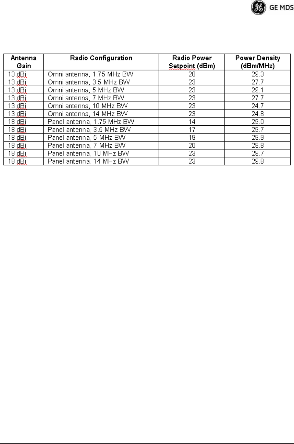
5.1.9 ERP Compliance at 3650 MHz
To maintain regulatory compliance for Effective Radiated Power (ERP)
of 1-Watt per MHz, the following table of transmit power settings must
Table 5-4. Examples of Antenna System Gain
vs. Power Output Setting (900 MHz)
Antenna System Gain
(Antenna Gain in dBi*
minus Feedline Loss in dB)
Maximum Power Setting
(PWR command)
EIRP
(in dBm)
Omni 6 (or less) 29 35
Omni 11 25 36
Yagi 11 23 36
Half Parabolic 16 20 36
Panel 17.4** 20 36
05-4446A01, Rev. D Mercury Reference Manual 171
be observed for the listed bandwidths and antenna types approved. Con-
sult the factory for other antenna options of lower gain.

172 Mercury Reference Manual 05-4446A01, Rev. D
5.2 dBm-WATTS-VOLTS CONVERSION
CHART
Table 5-5 is provided as a convenience for determining the equivalent
voltage or wattage of an RF power expressed in dBm.
Table 5-5. dBm-Watts-Volts conversion—for 50 ohm systems
dBm V Po
+53 100.0 200W
+50 70.7 100W
+49 64.0 80W
+48 58.0 64W
+47 50.0 50W
+46 44.5 40W
+45 40.0 32W
+44 32.5 25W
+43 32.0 20W
+42 28.0 16W
+41 26.2 12.5W
+40 22.5 10W
+39 20.0 8W
+38 18.0 6.4W
+37 16.0 5W
+36 14.1 4W
+35 12.5 3.2W
+34 11.5 2.5W
+33 10.0 2W
+32 9.0 1.6W
+31 8.0 1.25W
+30 7.10 1.0W
+29 6.40 800mW
+28 5.80 640mW
+27 5.00 500mW
+26 4.45 400mW
+25 4.00 320mW
+24 3.55 250mW
+23 3.20 200mW
+22 2.80 160mW
+21 2.52 125mW
+20 2.25 100mW
+19 2.00 80mW
+18 1.80 64mW
+17 1.60 50mW
+16 1.41 40mW
+15 1.25 32mW
+14 1.15 25mW
+13 1.00 20mW
+12 .90 16mW
+11 .80 12.5mW
+10 .71 10mW
+9 .64 8mW
+8 .58 6.4mW
+7 .500 5mW
+6 .445 4mW
+5 .400 3.2mW
+4 .355 2.5mW
+3 .320 2.0mW
+2 .280 1.6mW
+1 .252 1.25mW
dBm V Po
0 .225 1.0mW
-1 .200 .80mW
-2 .180 .64mW
-3 .160 .50mW
-4 .141 .40mW
-5 .125 .32mW
-6 .115 .25mW
-7 .100 .20mW
-8 .090 .16mW
-9 .080 .125mW
-10 .071 .10mW
-11 .064
-12 .058
-13 .050
-14 .045
-15 .040
-16 .0355
dBm mV Po
-17 31.5
-18 28.5
-19 25.1
-20 22.5 .01mW
-21 20.0
-22 17.9
-23 15.9
-24 14.1
-25 12.8
-26 11.5
-27 10.0
-28 8.9
-29 8.0
-30 7.1 .001mW
-31 6.25
-32 5.8
-33 5.0
-34 4.5
-35 4.0
-36 3.5
-37 3.2
-38 2.85
-39 2.5
-40 2.25 .1W
-41 2.0
-42 1.8
-43 1.6
-44 1.4
-45 1.25
-46 1.18
-47 1.00
-48 0.90
dBm mV Po
-49 0.80
-50 0.71 .01W
-51 0.64
-52 0.57
-53 0.50
-54 0.45
-55 0.40
-56 0.351
-57 0.32
-58 0.286
-59 0.251
-60 0.225 .001W
-61 0.200
-62 0.180
-63 0.160
-64 0.141
dBm V Po
-65 128
-66 115
-67 100
-68 90
-69 80
-70 71 .1nW
-71 65
-72 58
-73 50
-74 45
-75 40
-76 35
-77 32
-78 29
-79 25
-80 22.5 .01nW
-81 20.0
-82 18.0
-83 16.0
-84 11.1
-85 12.9
-86 11.5
-87 10.0
-88 9.0
-89 8.0
-90 7.1 .001nW
-91 6.1
-92 5.75
-93 5.0
-94 4.5
-95 4.0
-96 3.51
-97 3.2
dBm V Po
-98 2.9
-99 2.51
-100 2.25 .1pW
-101 2.0
-102 1.8
-103 1.6
-104 1.41
-105 1.27
-106 1.18
dBm nV Po
-107 1000
-108 900
-109 800
-110 710 .01pW
-111 640
-112 580
-113 500
-114 450
-115 400
-116 355
-117 325
-118 285
-119 251
-120 225 .001pW
-121 200
-122 180
-123 160
-124 141
-125 128
-126 117
-127 100
-128 90
-129 80 .1˜W
-130 71
-131 61
-132 58
-133 50
-134 45
-135 40
-136 35
-137 33
-138 29
-139 25
-140 23 .01˜W

05-4446A01, Rev. D Mercury Reference Manual 173
6TECHNICAL REFERENCE
6 Chapter Counter Reset Paragraph
Contents
6.1 DATA INTERFACE CONNECTORS ...................................... 175
6.1.1 LAN Port ................................................................................. 175
6.1.2 COM1 Port ............................................................................. 175
6.2 SPECIFICATIONS ................................................................. 176
6.3 NOTES ON SNMP................................................................. 179
6.3.1 Overview ................................................................................ 179

174 Mercury Reference Manual 05-4446A01, Rev. D

05-4446A01, Rev. D Mercury Reference Manual 175
6.1 DATA INTERFACE CONNECTORS
Two types of data interface connectors are provided on the front panel
of the transceiver—an RJ-45 LAN port, and a DB-9 serial port (COM1),
which uses the RS-232 (EIA-232) signaling standard.
The transceiver meets U.S.A.’s FCC Part 15, Class A limits when used
with shielded data cables.
6.1.1 LAN Port
Use the transceiver’s LAN port to connect the radio to an Ethernet net-
work. The transceiver provides a data link to an Internet Protocol-based
(IP) network via the Access Point station. Each radio in the network
must have a unique IP address for the network to function properly.
• To connect a PC directly to the radio’s LAN port, an RJ-45 to
RJ-45 cross-over cable is required.
• To connect the radio to a Ethernet hub or bridge, use a
straight-through cable.
The connector uses the standard Ethernet RJ-45 cables and wiring. For
custom-made cables, use the pinout information in Figure 6-1 and
Table 6-1.
Figure 6-1. LAN Port (RJ-45) Pinout
(Viewed from the outside of the unit)
6.1.2 COM1 Port
The COM1 serial port is a standard DB-9 female connector. Connect a
PC to the transceiver via this port with a DB-9M to DB-9F
Table 6-1. LAN Port (IP/Ethernet)
Pin Functions Ref.
1 Transmit Data (TX) High
2 Transmit Data (TX) Low
3 Receive Data (RX) High
4 Unused
5 Unused
6 Receive Data (RX) Low
7 Unused
8 Unused
CAUTION
RADIO FREQUENCY
INTERFERENCE
POTENTIAL
1 2 3 4 5 6 7 8
176 Mercury Reference Manual 05-4446A01, Rev. D
“straight-through” cable. These cables are available commercially, or
may be constructed using the pinout information in Table 6-2.
6.2 SPECIFICATIONS
General
• Raw Bit Rate: from 600 kbps to 12.7 Mbps
• Frequency Bands: 902-928 MHz ISM band
3.65-3.7 GHz Registered FCC band
• Bandwidths: 900 model—1.75, 3.5 MHz
3650 model—1.75, 3.5, 5, 7 MHz
• Orthogonal Frequency Division Multiplexing (OFDM)
• 200 Carriers per Channel
• Available Configurations:
• Access Point: Ethernet, Serial, GPS
• Remote: Ethernet, Serial, GPS
Radio
• System Gain: 140 dB for 1.75 MHz channel, 137 dB for
3.5 MHz channel
• Carrier Power—AP: -30 to +29 dBm, RM: 0 to +29 dBm (900
models); +23 dBm max. (3650 model)
• RF Output Impedance: 50 Ohms
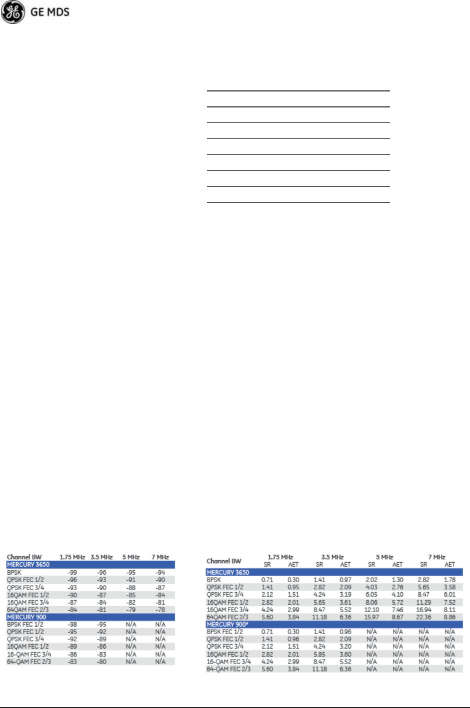
• Sensitivity and Signal Rate (see Table 6-3):
Table 6-3. Sensitivity and Signal Rate
Table 6-2. COM1 Port Pinout, DB-9F/RS-232 Interface
Pin Functions DCE
1 Unused
2 Receive Data (RXD) <—[Out
3 Transmit Data (TXD) —>[In
4 Unused
5 Signal Ground (GND)
6–9 Unused

05-4446A01, Rev. D Mercury Reference Manual 177
Note that the transceiver is a half-duplex radio, so maximum user
throughput is based on a configured or dynamic duty cycle, which is typ-
ically 50/50 indicating that half of the maximum throughput would be
available one way. The maximum user throughput is also based on high
protocol overhead from TCP/IP applications. For UDP applications,
these throughput numbers will increase.
Physical Interface
• Ethernet: 10/100BaseT, RJ-45
• Serial: 1,200 – 115,200 bps
• COM1: RS-232, DB-9F
• Antennas: TX/RX–TNC connector, GPS—SMA connector
• LED Indicators: PWR, COM1, LINK, LAN
Protocols (Pending—contact factory for details)
• Ethernet: IEEE 802.3, Spanning Tree (Bridging), VLAN, IGMP
• TCP/IP: DHCP, ICMP, UDP, TCP, ARP, Multicast, SNTP,
TFTP
• Serial: Encapsulation over IP (tunneling) for serial async multi-
drop protocols including MODBUS™, DNP.3, DF1, BSAP
GE MDS Cyber Security Suite, Level 1
• Encryption: AES-128.
• Authentication: 802.1x, RADIUS, EAP/TLS, PKI, PAP, CHAP
• Management: SSL, SSH, HTTPS
Management
• HTTP, HTTPS, TELNET, SSH, local console
• SNMPv1/v2/v3, MIB-II, Enterprise MIB
• SYSLOG
• MDS NETview MS™ compatible
Environmental
• Temperature: -40°C to +70°C (-40°F to +158°F)
• Humidity: 95% at 40°C (104°F) non-condensing
Electrical
• Input Power: 10-30 Vdc
• Current Consumption (nominal):
Mode Power 13.8 Vdc 24 Vdc
AP Transmit 25 W 1.8 A 1.0 A
AP Receive 8 W 579 mA 333 mA
RM Transmit 25W 1.8 mA 1.0 A
RM Receive 6.5W 471 mA 270 mA

178 Mercury Reference Manual 05-4446A01, Rev. D
Mechanical
• Case: Die Cast Aluminum
• Dimensions: 5.715 H x 20 W x 12.382 D cm. (2.25 H x 7.875 W
x 4.875 D in.)
• Weight: 1kg (2.2 lb.)
• Mounting options: Flat surface mount brackets, DIN rail, 19”
rack tray
External GPS PPS Option
Agency Approvals
• FCC Part 15.247 (DTS)
• CSA Class 1 Div. 2, (CSA C22.2-213-M1987 & CSA
C22.2-142-M1987) (UL1604 & UL916)
• IC RSS-210 “Issue 7”
NOTE: GE MDS products are manufactured under a quality system
certified to ISO 9001. GE MDS reserves the right to make
changes to specifications of products described in this manual
at any time without notice and without obligation to notify any
person of such changes.
6.3 NOTES ON SNMP
6.3.1 Overview
The firmware release described in this manual contains changes to the
transceiver’s SNMP Agent, several new MIB variables, and new Agent
configuration options. This guide reviews the changes and shows how
to properly configure the Agent to take advantage of these new features.
SNMPv3 Support
The updated SNMP Agent now supports SNMP version 3 (SNMPv3).
The SNMPv3 protocol introduces Authentication (MD5/SHA-1),
Encryption (DES), the USM User Table, and View-Based Access (refer
Parameter Minimum Maximum
Pulse Voltage (logic low) 0 V 1 V
Pulse Voltage (logic high) 1.7 V 10 V
Source Impedance (ohms) —200 Ω
Duty Cycle (ton) 0.0001% (1μsec) 50% (0.5 sec)
Operating Frequency 0.99999999 Hz
(-0.1 ppm error)
1.00000001 Hz
(+0.1 ppm error)
Module Clamping Voltage 2.7 V 3.3 V
Module Input Resistance 150 Ω (Vin >2.6 V) 10 kΩ (Vin < 2 V)
Input Hysteresis 7 mV N/A

05-4446A01, Rev. D Mercury Reference Manual 179
to RFC2574 for full details). The SNMP Agent has limited SNMPv3
support in the following areas:
• Only MD5 Authentication is supported (no SHA-1). SNMPv3
provides support for MD5 and SHA-1.
• Limited USM User Table Manipulation. The SNMP Agent
starts with 5 default accounts. New accounts can be added
(SNMPv3 adds new accounts by cloning existing ones), but
they will be volatile (will not survive a power-cycle).
New views cannot be configured on the SNMP Agent. Views are
inherited for new accounts from the account that was cloned.
The SNMP Agent uses one password pair (Authentication/Pri-
vacy) for all accounts. This means that when the passwords
change for one user, they change for all users.
SNMPv3 Accounts
The following default accounts are available for the SNMP Agent:
enc_mdsadmin—Read/write account using Authentication and Encryp-
tion.
auth_mdsadmin—Read/write account using Authentication.
enc_mdsviewer—Read only account using Authentication and Encryp-
tion.
auth_mdsviewer—Read only account using Authentication.
def_mdsviewer—Read only account with no Authentication or Encryp-
tion.
Context Names
The following Context Names are used (refer to RFC2574 for full
details):
Admin accounts: context_a/Viewer accounts: context_v.
All accounts share the same default passwords:
Authentication default password: MDSAuthPwd/Privacy default pass-
word: MDSPrivPwd.
Passwords can be changed either locally (via the console) or from an
SNMP Manager, depending on how the Agent is configured. If pass-
words are configured and managed locally, they are non-volatile and
will survive a power-cycle. If passwords are configured from an SNMP
manager, they will be reset to whatever has been stored for local man-
agement on power-cycle.

180 Mercury Reference Manual 05-4446A01, Rev. D
This behavior was chosen based on RFC specifications. The SNMP
Manager and Agent do not exchange passwords, but actually exchange
keys based on passwords. If the Manager changes the Agent’s password,
the Agent does not know the new password. The Agent only knows the
new key. In this case, only the Manager knows the new password. This
could cause problems if the Manager loses the password. If that hap-
pens, the Agent becomes unmanageable. Resetting the Agent’s pass-
words (and therefore keys) to what is stored in flash memory upon
power-cycle prevents the serious problem of losing the Agent’s pass-
words.
If passwords are managed locally, they can be changed on the Agent (via
the console). Any attempts to change the passwords for the Agent via an
SNMP Manager will fail when the Agent is in this mode. Locally
defined passwords will survive a power-cycle.
In either case, the SNMP Manager needs to know the initial passwords
being used in order to talk to the Agent. If the Agent’s passwords are
configured via the Manager, they can be changed from the Manager. If
the passwords are managed locally, then the Manager must be re-con-
figured with any password changes in order to continue talking to the
Agent.
Password-Mode Management Changes
When the password management mode is changed, the active passwords
used by the Agent may also change. Some common scenarios are dis-
cussed below:
Common Scenarios • Passwords are currently being handled by the Manager. The
assigned passwords are Microwave (Auth), and Rochester (Priv).
Configuration is changed to manage the passwords locally. The
passwords stored on the radio were Fairport (Auth), and
Churchville (Priv) (if local passwords have never been used,
then MDSAuthPwd and MDSPrivPwd are used). These pass-
words will now be used by the Agent to re-generate keys. The
Manager must know these passwords to talk to the Agent.
• Passwords are currently managed locally. The local passwords
are Fairport (Auth) and Churchville (Priv). Configuration is
changed to handle the passwords from the Manager. The same
passwords will continue to be used, but now the Manager can
change them.
• Passwords are currently managed locally. The local passwords
are Fairport (Auth) and Churchville (Priv). Passwords are changed
to Brighton (Auth) and Perinton (Priv). The Agent will immedi-
ately generate new keys based on these passwords and start
using them. The Manager will have to be re-configured to use
these new passwords.

05-4446A01, Rev. D Mercury Reference Manual 181
• Passwords are currently managed locally. The local passwords
are Fairport (Auth) and Churchville (Priv). Configuration is
changed to handle the passwords from the Manager. The Man-
ager changes the passwords to Brighton (Auth) and Perinton
(Priv). The radio is then rebooted. After a power-cycle, the radio
will use the passwords stored in flash memory, which are Fair-
port (Auth) and Churchville (Priv). The Manager must be re-con-
figured to use these new passwords.
Table 6-4. SNMP Traps (Sorted by Code)
SNMP Trap Severity Description
bootup(34) CRITICAL System Bootup
reboot(35) MAJOR User Selected Reboot
reprogStarted(36) INFORM Reprogramming Started
reprogCompleted(37) INFORM Reprogramming Completed
reprogFailed(38) MAJOR Reprogramming Failed
telnetLogin(39) MAJOR Telnet/SSH User login/logout
httpLogin(40) MAJOR HTTP User login/logout
logClear(41) INFORM Event Log Cleared
dhcpServer(42) INFORM DHCP server enabled/disabled
dhcpClient(43) INFORM DHCP client enabled/disabled
dhcpAddr(44) MINOR Obtained DHCP address
timeNotSet(45) INFORM Date/time not set
timeByUser(46) INFORM Date/time changed by user
timeFromServer(47) INFORM Date/time from server
consoleLogin(48) MAJOR Console user login/logout
httpLockdown(49) MAJOR HTTP Access locked down
parmChanged(50) INFORM Parameter changed
cfgscript(51) INFORM Configuration script generated/received
authKey(52) MAJOR Authorization key entered - valid/invalid
authDemo(53) MAJOR Demo authorization enabled/expired
maxDemos(54) CRITICAL Max demos reset/reached
modemRestart(55) MAJOR Modem restarted
internalError(56) MAJOR Internal error
gpsRestarted(57) MAJOR GPS Restarted
remoteConnection(58) INFORM Remote associated/disassociated
imageCopyStarted(59) INFORM Firmware image copy started
imageCopyComplete(60) INFORM Firmware image copy complete
imageCopyFailed(61) MAJOR Firmware image copy failed
connectionStatus(64) INFORM Connection status change
connAbort(65) MAJOR Connection aborted
authenticating(66) INFORM Authenticating to Access Point

182 Mercury Reference Manual 05-4446A01, Rev. D
association(67) MAJOR Associated to Access Point established/lost
redundLackRem(72) MAJOR Lack of associated remotes exceeded threshold for
P21 AP
redundRecvErr(73) MAJOR Packet receive errors exceeded threshold for P21
AP
redundForced(74) MAJOR P21 AP forced switchover
redundancySwitch(75) MAJOR P21 AP auto switchover
radioError(76) CRITICAL Radio error
procopen(77) MAJOR Proc filesystem access failed
procformat(78) MAJOR Unexpected proc filesystem format
csropen(79) MAJOR Failed to open CSR device
csrstatus(80) MAJOR CSR read failed
csrctrlsignal(81) MAJOR CSR write failed
bandwidthMismatch(83) INFORM Bandwidth of AP in Locations file does not match
this unit
gpsSync(84) INFORM GPS synchronized/lost sync
gpsTddSync(85) INFORM TDD synchronized/lost sync
tftpClientConn(86) INFORM TFTP Connection to Client Opened/Closed
tftpClientError(87) MAJOR Error in TFTP Transfer to Client
autoUpgrade(88) MAJOR Auto Firmware Upgrade Retry Scheduled/Starting
autoReboot(89) MAJOR Auto Firmware Boot Failed/Starting
certVerify(90) CRITICAL X.509 certificates loaded/failed
certChainVerify(91) CRITICAL Certificate chain verified/invalid
paTemp(92) MAJOR PowerAmp temperature Normal/Too hot
Table 6-4. SNMP Traps (Sorted by Code) (Continued)
SNMP Trap Severity Description

05-4446A01, Rev. D Mercury Reference Manual 183
7GLOSSARY OF TERMS
AND ABBREVIATIONS
7 Chapter Counter Reset Paragraph
If you are new to wireless IP/Ethernet systems, some of the terms used
in this manual might be unfamiliar. The following glossary explains
many of these terms and will prove helpful in understanding the opera-
tion of your radio network. Some of these terms do not appear in the
manual, but are often encountered in the wireless industry, and are there-
fore provided for completeness.
Access Point (AP)—The transceiver in the network that provides syn-
chronization information to one or more associated Remote units.
See “Network Configuration Menu” on Page 45.
AGC—Automatic Gain Control
Antenna System Gain—A figure, normally expressed in dB, repre-
senting the power increase resulting from the use of a gain-type antenna.
System losses (from the feedline and coaxial connectors, for example)
are subtracted from this figure to calculate the total antenna system gain.
AP—See Access Point
Association—Condition in which the frequency hopping pattern of the
Remote is synchronized with the Access Point station, and the Remote
is ready to pass traffic.
Authorization Key—Alphanumeric string (code) that is used to enable
additional capabilities in the transceiver.
Bit—The smallest unit of digital data, often represented by a one or a
zero. Eight bits usually comprise a byte.
Bits-per-second—See BPS.
BPDU—Bridge Protocol Data Units
BPS—Bits-per-second (bps). A measure of the information transfer rate
of digital data across a communication channel.
Byte—A string of digital data made up of eight data bits.
CSMA/CA—Carrier Sense Multiple Access/Collision Avoidance
CSMA/CD—Carrier Sense Multiple Access/Collision Detection
Cyclic Redundancy Check (CRC)—A technique used to verify data
integrity. It is based on an algorithm which generates a value derived

184 Mercury Reference Manual 05-4446A01, Rev. D
from the number and order of bits in a data string. This value is com-
pared with a locally-generated value and a match indicates that the mes-
sage is unchanged, and therefore valid.
Data Circuit-terminating Equipment—See DCE.
Data Communications Equipment—See DCE.
Datagram—A data string consisting of an IP header and the IP message
within.
Data Terminal Equipment—See DTE.
dBd—Decibels (dipole antenna).
dBi—Decibels referenced to an “ideal” isotropic radiator in free space.
Frequently used to express antenna gain.
dBm—Decibels referenced to one milliwatt. An absolute unit used to
measure signal power, as in transmitter power output, or received signal
strength.
DCE—Data Circuit-terminating Equipment (or Data Communications
Equipment). In data communications terminology, this is the “modem”
side of a computer-to-modem connection. COM1 Port of the transceiver
is set as DCE.
Decibel (dB)—A measure of the ratio between two signal levels. Fre-
quently used to express the gain (or loss) of a system.
Delimiter—A flag that marks the beginning and end of a data packet.
Device Mode—The operating mode/role of a transceiver (Access Point
or Remote) in a wireless network.
DHCP (Dynamic Host Configuration Protocol)—An Internet stan-
dard that allows a client (i.e. any computer or network device) to obtain
an IP address from a server on the network. This allows network admin-
istrators to avoid the tedious process of manually configuring and man-
aging IP addresses for a large number of users and devices. When a
network device powers on, if it is configured to use DHCP, it will con-
tact a DHCP server on the network and request an IP address.
The DHCP server will provide an address from a pool of addresses allo-
cated by the network administrator. The network device may use this
address on a “time lease” basis or indefinitely depending on the policy
set by the network administrator. The DHCP server can restrict alloca-
tion of IP addresses based on security policies. An Access Point may be
configured by the system administrator to act as a DHCP server if one
is not available on the wired network.

05-4446A01, Rev. D Mercury Reference Manual 185
Digital Signal Processing—See DSP.
DSP—Digital Signal Processing. DSP circuitry is responsible for the
most critical real-time tasks; primarily modulation, demodulation, and
servicing of the data port.
DTE—Data Terminal Equipment. A device that provides data in the
form of digital signals at its output. Connects to the DCE device.
Encapsulation—Process in by which, a complete data packet, such as
MODBUS™ frame or any other polled asynchronous protocol frame, is
placed in the data portion of another protocol frame (in this case IP) to
be transported over a network. Typically this action is done at the trans-
mitting end, before being sent as an IP packet to a network. A similar
reversed process is applied at the other end of the network extracting the
data from the IP envelope, resulting in the original packet in the original
protocol.
Endpoint—Data equipment connected to the Ethernet port of the radio.
Equalization—The process of reducing the effects of amplitude, fre-
quency or phase distortion with compensating networks.
Fade Margin—The greatest tolerable reduction in average received
signal strength that will be anticipated under most conditions. Provides
an allowance for reduced signal strength due to multipath, slight antenna
movement or changing atmospheric losses. A fade margin of 15 to 20
dB is usually sufficient in most systems.
Fragmentation—A technique used for breaking a large message down
into smaller parts so it can be accommodated by a less capable media.
Frame—A segment of data that adheres to a specific data protocol and
contains definite start and end points. It provides a method of synchro-
nizing transmissions.
Frequency Hopping—The spread spectrum technique used by the
transceiver, where two or more associated radios change their operating
frequencies many times per second using a set pattern. Since the pattern
appears to jump around, it is said to “hop” from one frequency to
another.
GPS—Global Positioning System. A constellation of orbiting satellites
used for navigation and timing data. Although 24 satellites are normally
active, a number of spares are also available in case of malfunction.
Originally designed for military applications by the U.S. Department of
Defense, GPS was released for civilian use in the 1980s. GPS satellites
operate in the vicinity of the “L” frequency band (1500 MHz).
Hardware Flow Control—A transceiver feature used to prevent data
buffer overruns when handling high-speed data from the connected data

186 Mercury Reference Manual 05-4446A01, Rev. D
communications device. When the buffer approaches overflow, the
radio drops the clear-to-send (CTS) line, that instructs the connected
device to delay further transmission until CTS again returns to the high
state.
Host Computer—The computer installed at the master station site, that
controls the collection of data from one or more remote sites.
HTTP—Hypertext Transfer Protocol
ICMP—Internet Control Message Protocol
IGMP (Internet Gateway Management Protocol)—Ethernet level
protocol used by routers and similar devices to manage the distribution
of multicast addresses in a network.
IEEE—Institute of Electrical and Electronic Engineers
IEEE 802.1Q—A standard for Ethernet framing which adds a four-byte
tag after the Ethernet header. The four-byte tag contains a VLAN ID and
a IEEE 802.1P priority value.
IEEE 802.1X—A standard for performing authentication and port
blocking. The 802.1X port/device denies access to the network until the
client device has authenticated itself.
Image (File)—Data file that contains the operating system and other
essential resources for the basic operation of the radio’s CPU.
LAN—Local Area Network
Latency—The delay (usually expressed in milliseconds) between when
data is applied at the transmit port at one radio, until it appears at the
receive port at the other radio.
MAC—Media Access Controller
MD5—A highly secure data encoding scheme. MD5 is a one-way hash
algorithm that takes any length of data and produces a 128 bit “finger-
print.” This fingerprint is “non-reversible,” it is computationally infea-
sible to determine the file based on the fingerprint. For more details
review “RFC 1321” available on the Internet.
MIB—Management Information Base
Microcontroller Unit—See MCU.
Mobility—Refers to a station that moves about while maintaining
active connections with the network. Mobility generally implies phys-
ical motion. The movement of the station is not limited to a specific net-
work and IP subnet. In order for a station to be mobile it must establish

05-4446A01, Rev. D Mercury Reference Manual 187
and tear down connections with various access points as it moves
through the access points' territory.
Mode—See Device Mode.
MTBF—Mean-Time Between Failures
Multiple Address System (MAS)—See Point-Multipoint System.
NMEA—National Marine Electronics Association. National body that
established a protocol for interfacing GPS data between electronic
equipment.
Network Name—User-selectable alphanumeric string that is used to
identify a group of radio units that form a communications network. The
Access Point and all Remotes within a given system should have the
same network address.
Network-Wide Diagnostics—An advanced method of controlling and
interrogating GE MDS radios in a radio network.
NTP—Network Time Protocol
Packet—The basic unit of data carried on a link layer. On an IP network,
this refers to an entire IP datagram or a fragment thereof.
PING—Packet INternet Groper. Diagnostic message generally used to
test reachability of a network device, either over a wired or wireless net-
work.
PKI—Private Key Infrastructure. A set of policies and technologies
needed to create, store, and distribute Public Key Certificates used to
protect the security of network communications.
Point-to-Multipoint System—A radio communications network or
system designed with a central control station that exchanges data with
a number of remote locations equipped with terminal equipment.
Poll—A request for data issued from the host computer (or master PLC)
to a remote device.
Portability—A station is considered connected when it has successfully
authenticated and associated with an access point. A station is consid-
ered authenticated when it has agreed with the access point on the type
of encryption that will be used for data packets traveling between them.
The process of association causes a station to be bound to an access
point and allows it to receive and transmit packets to and from the access
point. In order for a station to be associated it must first authenticate
with the access point. The authentication and association processes
occur automatically without user intervention.

188 Mercury Reference Manual 05-4446A01, Rev. D
Portability refers to the ability of a station to connect to an access point
from multiple locations without the need to reconfigure the network set-
tings. For example, a remote transceiver that is connected to an access
point may be turned off, moved to new site, turned back on, and,
assuming the right information is entered, can immediately reconnect to
the access point without user intervention.
PLC—Programmable Logic Controller. A dedicated microprocessor
configured for a specific application with discrete inputs and outputs. It
can serve as a host or as an RTU.
PuTTY—A free implementation of Telnet and SSH for Win32 and
Unix platforms. It is written and maintained primarily by Simon
Tatham. Refer to http://www.pobox.com/~anakin/ for more information.
RADIUS—Remote Authentication Dial In User Service. An authenti-
cation, authorization, and accounting protocol used to secure remote
access to a device or network.
Remote—A transceiver in a network that communicates with an asso-
ciated Access Point.
Remote Terminal Unit—See RTU.
RFI—Radio Frequency Interference
Roaming—A station's ability to automatically switch its wireless con-
nection between various access points (APs) as the need arises. A station
may roam from one AP to another because the signal strength or quality
of the current AP has degraded below what another AP can provide.
Roaming may also be employed in conjunction with Portability where
the station has been moved beyond the range of the original AP to which
it was connected. As the station comes in range of a new AP, it will
switch its connection to the stronger signal. Roaming refers to a station's
logical, not necessarily physical, move between access points within a
specific network and IP subnet.
RSSI—Received Signal Strength Indicator
RTU—Remote Terminal Unit. A data collection device installed at a
remote radio site.
SCADA—Supervisory Control And Data Acquisition. An overall term
for the functions commonly provided through an MAS radio system.
SNMP—Simple Network Management Protocol
SNR—Signal-to-Noise Ratio. A measurement of the desired signal to
ambient noise levels.This measurement provides a relative indication of
signal quality. Because this is a relative number, higher signal-to-noise
ratios indicate improved performance.

05-4446A01, Rev. D Mercury Reference Manual 189
SNTP—Simple Network Time Protocol
SSL—Secure Socket Layer
SSH—Secure Shell
STP—Spanning Tree Protocol
Standing-Wave Ratio—See SWR.
SWR—Standing-Wave Ratio. A parameter related to the ratio between
forward transmitter power and the reflected power from the antenna
system. As a general guideline, reflected power should not exceed 10%
of the forward power (≈ 2:1 SWR).
TCP—Transmission Control Protocol
TFTP—Trivial File Transfer Protocol
Trap Manager—Software that collects SNMP traps for display or log-
ging of events.
UDP—User Datagram Protocol
UTP—Unshielded Twisted Pair
VLAN—Virtual Local Area Network. A network configuration
employing IEEE 802.1Q tagging, which allows multiple groups of
devices to share the same physical medium while on separate broadcast
domains.

190 Mercury Reference Manual 05-4446A01, Rev. D

05-4446A01, Rev. D Mercury Reference Manual I-1
Index
Numerics
100BaseT 55, 161
10BaseT 55, 161
16QAM 74
64QAM 74
802.11b 12
A
Access Point (AP), defined 183
accessories 19
Active Scanning, defined 183
adapter
TNC Male-to-N Female 19
Adaptive
Modulation 72
Split 73
Add
Associated Remotes 96
Remote 96
Address to Ping 134
Advanced
Configuration 65
Control 69
AES encryption 4
agency approvals 178
alarm conditions 152
correcting 153
Alarmed 150
alarms 151
Altitude 115
antenna
900 MHz 5
aiming 156
cross-polarization 15
directional 5, 168
for repeater stations 15
GPS 5, 165
receiving 19
minimizing interference 15
Minimum Feedline Length versus Antenna Gain 166
omni-directional 5, 14, 19, 164
polarization 164
selection 163
SWR check 155
system gain
defined 183
vs. power output setting 170
vertical separation 15
Yagi 14, 19, 164
AP
current name 143
Location Info Config 46
locations 59—62
application
IP-to-Serial 81
Mixed-Modes 86
Point-to-Multipoint Serial-to-Serial 83
Point-to-Point Serial-to-Serial 82
Serial Port 86
approvals
agency 178
Approved Remotes 95
ARQ 73
Block Lifetime 73
Block Size 73
Receiver Delay 73
Transmitter Delay 73
Window Size 73
Associated 150
Remotes 43, 117
association
defined 183
process 116
attenuation 24
Auth Server
Address 98
Port 98
Shared Secret 98
Auth Traps Status 59
Authenticating 150
authentication
device 96
user 97
Authorization
Codes 123, 135
Key 135
defined 183
Authorized Features 135
Auto Firmware Upgrade 124
Automatic Repeat Request 73
Auto-Upgrade/Remote-Reboot 137
Average
RSSI 121
SNR 121
B
Backhaul
for serial radio networks 11
Network 11
bandpass filter 168
baud rate 78, 81
console 75
serial data 75
Begin Wizard 77
Bit, defined 183
Bits-per-second (bps), defined 183
BPDU 56
defined 183
BPS, defined 183
BPSK 74
Bridge
Configuration 46
Forward Delay 57
Hello Time 56
Priority 56
Protocol Data Unit 56
Bridge Status 110
Buffer Size 78, 79, 80, 81
BW 61
Byte Format 78
byte format 79, 81
bytes
defined 183
received 114
sent 114

I-2 Mercury Reference Manual 05-4446A01, Rev. D
C
cable
crossover 36, 38, 175
EIA-232 Shielded Data 19
Ethernet crossover 14, 25, 39
Ethernet RJ-45 Crossover 19
Ethernet RJ-45 Straight-thru 19
feedlines 165
serial communications 25, 37
straight-through 38, 39, 175
certificate
files 96
type 100
Certificate Filename 100
Change
Admin Password 94
Guest Password 94
channel
selection 69
single frequency 68
type 72
CHANNELS 61
clear
Ethernet statistics 114
Event Log 112
MDS wireless statistics 114
Collocating Multiple Radio Networks 16
Commit Changes and Exit Wizard 78, 79, 80, 81
communication
peer-to-peer 10
Compression 144
Computer
host, defined 186
Config
filename 132
configuration 25, 80
advanced 65
defaults 25
DHCP server 50
editing files 133
Ethernet Port 55
file 25, 147
IP address 53
network 45
P23 8
protected network 8
radio parameters 63—87
RADIUS 98
redundant 8
script 123, 130
SNMP Agent 57
TCP Mode 80
UDP mode 77
Connecting 150
Connection Status 43, 118, 120, 142
connectionware 144
connector
descriptions 175
Ethernet 10
console baud rate 75, 108
Contact 109
context names 179
Corrected FEC Count 122, 143
cost of deployment 12
Count 134
CRC (Cyclic Redundancy Check), defined 183
CSMA
CA, defined 183
CD, defined 183
Current Alarms 112
Current AP 69
Eth Address 118
IP Address 118
Name 118, 120, 143
Current IP
Address 42, 50, 53
Gateway 50, 53
Netmask 50, 53
Cyclic Prefix 72
D
data
baud rate 80
buffering 76
compression 72
encryption 95
VLAN ID 49
VLAN Subnet Config 49
Datagram, defined 184
Date 108
Format 108
dB, defined 184
dBd, defined 184
dBi, defined 184
dBm
defined 184
watts-volts conversion 172
DCE, defined 184
Default Route IF 49
defaults
resetting 136
Delete
All Remotes 96
Remote 96
Delimiter, defined 184
deployment costs 12
Description 109
Device
Auth Mode 95
Authentication 96
Information 45
Menu 108
Mode 42
defined 184
Name 42, 109, 134
Security Menu 92
Status 42, 117, 150
messages 150
DHCP 53
defined 184
DNS address 52
ending address 52
Netmask 52
Server 49
Config 49
Configuration 46, 47
Status 52
starting address 52
WINS address 52

05-4446A01, Rev. D Mercury Reference Manual I-3
Diagnostic Tools 151
dimensions 161
DIN Rail Mounting Bracket 20
DKEY command 155
Downlink 143
Percentage 73
DSP (Digital Signal Processing), defined 185
DTE
defined 185
DUR 61
E
EIA-232 13
Embedded Management System 25
Enable Filtering 56
encapsulation
defined 185
serial 75
transparent 75
encryption 5
AES 4
Phrase 95
Endpoint
defined 185
Equalization, defined 185
Ethernet
filtering configuration 55
Port Config 46
port enable 55
port follows association 55
port phy rate 55
event
Alarms 152
Critical 152
Informational 152
Major 152
Minor 152
Temporary Informational 152
Event Log 110, 113, 150, 151, 152, 153
clear 112
filename 112
host address 112
Menu 112
send 112
view 112
events 151
F
factory defaults
resetting 136
Fade Margin 185
FEC 72
count
corrected 122, 143
total 122, 143
uncorrected 122, 143
Total 143
feedline
selection 163, 165
file
certificate 96
MIB 33
Filename 126
filtering
enable 56
firmware
automatic upgrade 124
current 127
filename 129
for Upgrade 137
installing 128
upgrade 129, 137
version 43, 124
Flow Control
hardware, defined 185
Force
Switchover 102
Fragmentation
defined 185
frame
defined 185
duration 68
Free Run 24, 27, 29
frequency
control 65
hopping, defined 185
mode 26, 67
offset
RX 143
TX 143
fuse 19
G
gain
antenna, defined 183
gateway
current IP 53
Glossary 183—189
GPS
antenna 165
Configuration 45
defined 185
external GPS PPS option 9, 178
Firmware Version 115
information 115
latitude 61
longitude 61
Precise Positioning Service 115
pseudo-random noise 115
receiver 42
satellite fix 62
Serial Number 115
Status 110
Menu 115
Streaming Configuration 106
time of day 62
timing signals 42
to Console Baud Rate 106
UDP Server IP Address 106
UDP Server UDP Port 106
GROUP 61
H
hand-off 70
Signal and Distance 70
Signal, Distance, and Bearing 70
Strict Connection 70
Strict Distance 70

I-4 Mercury Reference Manual 05-4446A01, Rev. D
Strict Signal 70
Hardware
Event Triggers 102, 104
flow control, defined 185
Version 43
hop
pattern 68, 144
pattern offset 68
Hopping
frequency, defined 185
Host
computer 85
computer, defined 186
HTTP
Auth Mode 93
defined 186
Mode 93
HyperTerminal 36, 37
Hysteresis Margin 72, 73
I
IANA 76
ICMP
defined 186
IEEE
802.1Q 48, 49, 186
802.1X 186
defined 186
IEEE 802.1x
Device Authentication 4, 51, 96
IETF standard RFC1213 57
IGMP 76
defined 186
Image
Copy 127
file, defined 186
Verify 127
iNET II, differences of 156
Init/Hardware Error 104
Installation
antenna & feedline 163
feedline selection 165
general information 5
mobile 9
planning 161
requirements 161
site selection 162
site survey 167
Interference 168
inter-frame packet delay 80
Internal Radio Status 110
Menu 119
Internet
Assigned Numbers Authority 76
Control Message Protocol, defined 186
Inter-Packet Delay 78, 79, 81
IP 12, 50
Address 26, 42, 53, 133
Configuration 47
Mode 49, 50, 53
Configuration 46
current
address 50, 53
gateway 50
netmask 50
gateway 53, 133
netmask 53
Protocol 78, 79
static
address 49
netmask 49
tunneling 75
K
KEY
command 155
transmitter, for antenna SWR check 155
L
Lack of Associated Remotes Exceeded Threshold 103, 104
Menu 105
Lack of Remotes for 105
LAN
defined 186
wireless 10, 12
LAT 61
Latency, defined 186
Latitude 115
LED
COM1 30
LAN 29, 38, 39, 148
LINK 29, 30, 148, 157, 167
PWR 29, 30, 113, 148, 152, 153
use during troubleshooting 147
Local
Area Network, defined 186
Console 36
session 37
Location 109, 134
logged events 153
LONG 61
Longitude 115
Lost Carrier Detected 114, 151
M
MAC 61
ADDR 143
Main Menu 43
Maintenance/Tools 45
Menu 122
Manage Certificates 92
Management
VLAN ID 49
VLAN Mode 49
VLAN Subnet Config 49
Management System 25, 74, 129
as a troubleshooting tool 148
user interfaces 33
manuals
Reference Manual 3
Start-Up Guide 3
margin
hysteresis 73
protection 73
Max
Modulation 72
Transmit Power 65
Max Remotes 95

05-4446A01, Rev. D Mercury Reference Manual I-5
Maximum Receive Errors 105
MD5, defined 186
MDS Security Suite 17
measurements
radio 155
Media Access Controller, defined 186
MIB
defined 186
files 33, 57
version II 57
mobile 9
Mobility
defined 186
MODBUS 87
ASCII 89
RTU 89
Modbus
TCP Server 87
Mode 61, 77
Device, defined 184
mixed 85
Model 108
modulation protection 73
MTBF, defined 187
multicast addressing 76
N
NAME 61
NEMA 12
netmask
current IP 53
network
Administrator 9
Configuration 44
coverage 144
design 14
antennas 15
collocating multiple radio networks 16
name 15
repeaters 14
using multiple Access Points 16
Using the AP as a Store-and-Forward
Packet Repeater 15
Using two transceivers to form a repeat-
er station 14
Event Triggers 102, 103
Interface
Config 46
Error 103
LAN 10
name 17, 23, 26, 64, 144
defined 187
tabletop 23
Time Protocol (NTP), defined 187
WAN 1 0
-wide diagnostics 187
NTP (Network Time Protocol), defined 187
Number of Satellites 115
O
OFDM 4
OFFSET 61
optimizing
radio performance 139
Orthogonal Frequency Division Multiplexing 4
Outgoing Connections Inactivity Timeout 80
P
P23 8
Packet
defined 187
Receive Errors Exceeded Threshold 103, 105
Menu 105
Size 134
Statistics 110, 113, 151
packets
dropped 114, 151
received 114
sent 114
password
admin 94
guest 94
Pattern Offset 144
PC
connection to transceiver 25
host 85
peer-to-peer communications 10
Performance
Information 45
Trend 110
PING 23, 30, 122, 167
address 134
defined 187
utility 123
PKI 187
PLC 13
defined 188
point-to-multipoint 16
defined 187
Point-to-Point
LAN Extension 11
Link 11
Poll, defined 187
port
access 48, 49
COM1 13, 25, 26, 27, 28, 33, 36, 38, 44, 74, 82, 87, 129,
163, 175
COM2 26, 82
Ethernet 23, 48, 49
GPS antenna 27, 29
IP 82
LAN 25, 26, 27, 28, 33, 36, 38, 39, 53, 74, 129, 163, 175
PWR 27, 28
RX2 27, 29, 165
serial 12
trunk 49
TX/RX1 antenna 27, 29
Portability, defined 187
power
connector 24
how much can be used 167
primary 24
transmitter power output 155
PPS 115
Precise Positioning Service 115
PRN 115

I-6 Mercury Reference Manual 05-4446A01, Rev. D
Programmable Logic Controller 13
Protection Margin 72, 73
protocol
DHCP 53
HTTP 33
HTTPS 33
ICMP 48
defined 186
IP 12, 26, 50, 74
SNMP 33, 48, 50, 57, 178
defined 188
SNTP 46, 189
SSH 33, 36
STP, defined 189
Syslog 112
TCP 75, 80, 81, 85
defined 189
Telnet 33, 36, 38, 48
TFTP 48, 128
defined 189
UDP 75, 76, 81, 82, 85
defined 189
Pseudo-Random Noise 115
PuTTY usage 41
defined 188
Q
QoS 4
QPSK 74
Quality of Service 4
R
Radio
Configuration 44
Details 121
Event Triggers 102, 103
Frequency Interference 17
interference 168
Mode 138
performance optimization 139
Remote, defined 188
Test 124
RADIUS 188
configuration 92, 98
User Auth Mode 98
range, transmission 12
ranging 150
Read Community String 58
reboot
Device 127
on upgrade 137
Remotes 137
receive
errors 114, 151
power 65
Received Signal Strength Indicator 24, 163
defined 188
Redundancy
Configuration 45, 102
Options 102, 104
Using multiple Access Points 16
Remote
add 96
associated 96
approved 95
Database 117
delete 96
all 96
Max 6
Performance Database 117
radio, defined 188
Standard 6
Terminal Unit 13
defined 188
view approved 96
Repeater 14
antennas 15
Network Name 15
Using the AP as a Store-and-Forward Packet Repeater 15
Using two transceivers to form a repeater station 14
Reprogramming 123
Menu 125
Reset to Factory Defaults 123, 136
Retries 151
Retrieve
Certificate 100
File 127, 133
Retry errors 151
RF
bandwidth 26, 68
Output Power 26
power output level 24
RFI 17
defined 188
Roaming, defined 188
RSSI 24, 121, 142, 143, 156, 163
average 121
defined 188
RTU 13, 82, 86
defined 188
RX
Frequency Offset 122, 143
IP Port 78
S
satellite
fix status 43, 115
number of 115
SCADA 12, 13, 76
defined 188
Scanning 150
script
configuration 123
security
Configuration 45
Menu 91
device level 96
general information 5
monitoring 13
password 25
risk management 18
suite 17
wireless access 96
Send
Event Log 112
file 133
GPS via UDP 106

05-4446A01, Rev. D Mercury Reference Manual I-7
Serial
Configuration Wizard 76
data baud rate 75
encapsulation 75
Number 43, 108
Port
Configuration 44
radio networks, backhaul 11
server
status 52
time 113
signal
strength 163
-to-noise ratio 115
defined 188
Simple Network
Management Protocol, defined 188
Time Protocol 62
defined 189
Single
channel operation 24
Frequency Channel 26, 68
SINGLE_CHAN 62
Site selection 162
SNMP 33, 50
Agent Config 46
defined 188
Mode 58, 59
traps 181
usage 178
V3 Passwords 59
SNMPv3 178
accounts 179
SNR 72, 115, 121, 143
average 121
defined 188
max 74
min 74
range 73
SNTP
defined 189
Server 46
configuration 62
Spanning Tree Protocol, defined 189
Spectrum Analyzer Mode 139
spread-spectrum transmission 5
SSH 36, 97
Access 93
defined 189
SSL, defined 189
Standing Wave Ratio 189
Starting
Information Screen 38, 44
Static IP
Address 49, 50, 53
Gateway 54
Netmask 49, 50, 53
Status 42, 77, 78, 80, 81
alarmed 150
associated 150
authenticating 150
connecting 150
scanning 150
STP, defined 189
Stream GPS to Console 106
subnet 53
SWR 155, 189
defined 189
performance optimization 155
Syslog Server Address 112
system gain, antenna (defined) 183
T
tabletop network 23
TCP 75, 85
client 75
defined 189
server 75
TDD
Sync Mode 15, 69, 144
TDD Sync 26
Telnet 36, 74, 82, 97
Access 93
session 38
Utility 124
Test
Burst Percentage 138
Channel 138
Key 138
RF Bandwidth 138
Status 138
Transmit Power 138
TFTP
Block Size 101
defined 189
Host Address 60, 100, 126, 129, 132, 133
Timeout 101
Time 108
Connected 118
Division Duplex 69
server 113
Total FEC Count 122, 143
transceiver
models 6
Transfer Options 100, 112
Transmission
Control Protocol, defined 189
range 12
transmit
max power 65
power 64, 121, 142
transparent encapsulation 75
Trap
Community String 58
Manager 59
defined 189
Version 59
triggers
hardware event 104
radio event 103
Troubleshooting 147—155
Using the Embedded Management System 148
TX
Frequency Offset 121, 143
IP
Address 78
Port 78

I-8 Mercury Reference Manual 05-4446A01, Rev. D
U
UDP 75, 82, 85
defined 189
mode 77
multicast 76
Point-to-Point 78
Uncorrected FEC Count 122, 143
Unit Password 26
upgrade
firmware 137
Uplink 143
Uptime 43, 108
User
Auth Fallback 93
Auth Method 93
Authentication 97
Datagram Protocol, defined 189
Passwords 93
Menu 94
User Auth Mode 98
UTC Time Offset 109
UTP, defined 189
V
V3
Authentication Password 58
View
Approved Remotes 96
Current Settings 77
Event Log 112
Menu 113
VLAN 48, 189
data 48, 49
Ethport Mode 49
ID 49
management 48, 49
Status 46, 47, 49
Voice over IP 4, 13
VoIP 4, 13
volts-dBm-watts conversion 172
W
watts-dBm-volts conversion 172
Web browser 36, 74
session 39
Wireless
LAN 10
Network Status 110
Menu 116
Security 92
Menu 94
wizard
serial configuration 76
Write community String 58
Y
Yagi antenna 164

IN CASE OF DIFFICULTY...
GE MDS products are designed for long life and trouble-free operation. However, this equipment, as with
all electronic equipment, may have an occasional component failure. The following information will assist
you in the event that servicing becomes necessary.
TECHNICAL ASSISTANCE
Technical assistance for GE MDS products is available from our Technical Support Department during
business hours (8:00 A.M.—5:30 P.M. Eastern Time). When calling, please give the complete model number
of the radio, along with a description of the trouble/symptom(s) that you are experiencing. In many cases,
problems can be resolved over the telephone, without the need for returning the unit to the factory. Please
use one of the following means for product assistance:
Phone: 585 241-5510 E-Mail: TechSupport@GEmds.com
FAX: 585 242-8369 Web: www.GEmds.com
FACTORY SERVICE
Component level repair of this equipment is not recommended in the field. Many components are installed
using surface mount technology, which requires specialized training and equipment for proper servicing.
For this reason, the equipment should be returned to the factory for any PC board repairs. The factory is best
equipped to diagnose, repair and align your radio to its proper operating specifications.
If return of the equipment is necessary, you must obtain a Service Request Order (SRO) number. This
number helps expedite the repair so that the equipment can be repaired and returned to you as quickly as
possible. Please be sure to include the SRO number on the outside of the shipping box, and on any corre-
spondence relating to the repair. No equipment will be accepted for repair without an SRO number.
SRO numbers are issued online at www.GEmds.com/support/product/sro/. Your number will be issued
immediately after the required information is entered. Please be sure to have the model number(s), serial
number(s), detailed reason for return, "ship to" address, "bill to" address, and contact name, phone number,
and fax number available when requesting an SRO number. A purchase order number or pre-payment will
be required for any units that are out of warranty, or for product conversion.
If you prefer, you may contact our Product Services department to obtain an SRO number:
Phone Number: 585-241-5540
Fax Number: 585-242-8400
E-mail Address: productservices@GEmds.com
The radio must be properly packed for return to the factory. The original shipping container and packaging
materials should be used whenever possible. All factory returns should be addressed to:
GE MDS, LLC
Product Services Department
(SRO No. XXXX)
175 Science Parkway
Rochester, NY 14620 USA
When repairs have been completed, the equipment will be returned to you by the same shipping method used
to send it to the factory. Please specify if you wish to make different shipping arrangements. To inquire
about an in-process repair, you may contact our Product Services Group using the telephone, Fax, or E-mail
information given above.

GE MDS, LLC
Rochester, NY 14620
General Business: +1 585 242-9600
FAX: +1 585 242-9620
Web: www.GEmds.com
175 Science Parkway