GE MDS DS-MERCURY900 Mercury 900 Wireless Transceiver User Manual
GE MDS LLC Mercury 900 Wireless Transceiver
GE MDS >
Contents
- 1. manual pt 1
- 2. manual pt 2
- 3. User Manual 1
- 4. User Manual 2
- 5. Users Manual Revised 121908 Part 1
- 6. Users Manual Revised 121908 Part 2
- 7. Users Manual Revised 121908 Part 3
Users Manual Revised 121908 Part 1
Reference Manual
05-4446A01, Rev. D
DECEMBER 2008
Wireless IP/Ethernet Transceiver
Covering all AP and Remote Units
including Mercury 900, 3650, and Option Set 1 Remotes
MDS Mercury SeriesTM


05-4446A01, Rev. D Mercury Reference Manual i
TABLE OF CONTENTS
1 PRODUCT OVERVIEW AND APPLICATIONS ......... 1
1.1 ABOUT THIS MANUAL................................................................................................... 3
1.1.1 Start-Up Guide .................................................................................................................... 3
1.1.2 Online Access to Manuals ................................................................................................... 3
1.1.3 Conventions Used in This Manual ....................................................................................... 3
1.2 PRODUCT DESCRIPTION............................................................................................. 4
1.2.1 Model Offerings ................................................................................................................... 6
1.2.2 Remote Radio with Option Set 1 .........................................................................................7
1.2.3 GE MDS P23 Protected Network (Redundant) Configuration ............................................. 8
1.2.4 External GPS PPS Option ................................................................................................... 9
1.3 APPLICATIONS ..............................................................................................................9
1.3.1 Mobile/Fixed Data System .................................................................................................. 9
1.3.2 Wireless LAN ..................................................................................................................... 10
1.3.3 Point-to-Point LAN Extension .............................................................................................11
1.3.4 Serial Radio Network Connectivity .....................................................................................11
1.3.5 Multiple Protocols and/or Services .....................................................................................11
1.3.6 Wireless LAN with Mixed Services .................................................................................... 12
1.3.7 Upgrading Older Wireless Network with Serial Interfaces ................................................. 13
1.4 NETWORK DESIGN CONSIDERATIONS.................................................................... 14
1.4.1 Extending Network Coverage with Repeaters ................................................................... 14
1.4.2 Protected Network Operation using Multiple Access Points .............................................. 16
1.4.3 Collocating Multiple Radio Networks ................................................................................. 16
1.5 GE MDS CYBER SECURITY SUITE............................................................................ 17
1.6 ACCESSORIES ............................................................................................................ 19
2 TABLETOP EVALUATION & TEST SETUP............. 21
2.1 OVERVIEW................................................................................................................... 23
2.2 STEP 1
—
CONNECT THE ANTENNA PORTS............................................................. 23
2.3 STEP 2
—
CONNECT THE PRIMARY POWER ............................................................ 24

ii
Mercury Reference Manual 05-4446A01, Rev. D
2.4 STEP 3
—
CONNECT PC TO THE TRANSCEIVER...................................................... 25
2.5 STEP 4
—
REVIEW TRANSCEIVER CONFIGURATION 25
2.5.1 Getting Started 25
2.5.2 Procedure 25
2.5.3 Basic Configuration Defaults 25
2.6 STEP 5
—
CONNECT LAN OR SERIAL DATA EQUIPMENT 26
2.6.1 Option 1 Set (MaxRM) Connectors 28
2.7 STEP 6
—
CHECK FOR NORMAL OPERATION 29
3 EMBEDDED MANAGEMENT SYSTEM.................. 31
3.1 MS INTRODUCTION.................................................................................................... 33
3.1.1 Differences in the User Interfaces .....................................................................................33
3.2 ACCESSING THE MENU SYSTEM ............................................................................. 35
3.2.1 Methods of Control ............................................................................................................ 36
3.2.2 PC Connection and Log In Procedures ............................................................................. 36
3.2.3 Navigating the Menus ........................................................................................................ 40
3.3 BASIC OVERVIEW OF OPERATION........................................................................... 42
3.3.1 Starting Information Screen ............................................................................................... 42
3.3.2 Main Menu ......................................................................................................................... 43
3.4 CONFIGURING NETWORK PARAMETERS ............................................................... 45
3.4.1 Network Configuration Menu .............................................................................................45
3.4.2 Ethernet Port Configuration Menu ..................................................................................... 55
3.4.3 Bridge Configuration .......................................................................................................... 56
3.4.4 SNMP Agent Configuration ................................................................................................ 57
3.4.5 AP Location Push Config Menu ......................................................................................... 59
3.4.6 SNTP Server Configuration ............................................................................................... 62
3.5 RADIO CONFIGURATION............................................................................................ 63
3.5.1 Radio Configuration Menu ............................................................................................... 63
3.5.2 Serial Port Configuration ................................................................................................... 74
3.6 MODBUS / TCP SERVER CONFIGURATION ............................................................. 87
3.6.1 Modbus/TCP in Mercury Transceivers
—
An Overview ...................................................... 87
3.6.2 Menu Selections ................................................................................................................ 88
3.7 SECURITY CONFIGURATION MENU ......................................................................... 91
3.7.1 Device Security Menu ....................................................................................................... 92

05-4446A01, Rev. D Mercury Reference Manual iii
3.7.2 Wireless Security Menu ..................................................................................................... 94
3.7.3 IEEE 802.1x Device Authentication ................................................................................... 96
3.7.4 Manage Certificates .......................................................................................................... 98
3.8 REDUNDANCY CONFIGURATION (AP ONLY) ......................................................... 101
3.9 GPS CONFIGURATION (REMOTE ONLY) ................................................................ 106
3.10 DEVICE INFORMATION MENU............................................................................... 108
3.11 PERFORMANCE INFORMATION MENU................................................................. 109
3.12 MAINTENANCE/TOOLS MENU............................................................................... 122
3.12.1 Installing Firmware via TFTP ........................................................................................ 128
3.12.2 Auto Firmware Upgrade Menu (AP Only) ..................................................................... 137
3.13 PERFORMANCE OPTIMIZATION............................................................................ 139
3.13.1 Proper Operation
—
What to Look For ........................................................................... 142
4 TROUBLESHOOTING & RADIO
MEASUREMENTS................................................... 145
4.1 TROUBLESHOOTING................................................................................................ 147
4.1.1 Interpreting the Front Panel LEDs ................................................................................... 147
4.1.2 Troubleshooting With the Embedded Management System ........................................... 148
4.1.3 Using Logged Operation Events ..................................................................................... 151
4.1.4 Alarm Conditions ............................................................................................................. 152
4.1.5 Correcting Alarm Conditions ............................................................................................ 153
4.1.6 Logged Events ................................................................................................................ 153
4.2 RADIO (RF) MEASUREMENTS................................................................................. 155
4.2.1 Antenna System SWR and Transmitter Power Output .................................................... 155
4.2.2 Antenna Aiming
—
For Directional Antennas .................................................................... 156
5 PLANNING A RADIO NETWORK .......................... 159
5.1 INSTALLATION PLANNING ....................................................................................... 161
5.1.1 General Requirements .................................................................................................... 161
5.1.2 Site Selection .................................................................................................................. 162
5.1.3 Terrain and Signal Strength ............................................................................................. 163
5.1.4 Antenna & Feedline Selection ......................................................................................... 163
5.1.5 How Much Output Power Can be Used? ........................................................................ 167
5.1.6 Conducting a Site Survey ................................................................................................ 167
5.1.7 A Word About Radio Interference .................................................................................... 168

iv
Mercury Reference Manual 05-4446A01, Rev. D
5.1.8 ERP Compliance at 900 MHz .......................................................................................... 170
5.1.9 ERP Compliance at 3650 MHz ........................................................................................ 171
5.2 dBm-WATTS-VOLTS CONVERSION CHART............................................................ 172
6 TECHNICAL REFERENCE..................................... 173
6.1 DATA INTERFACE CONNECTORS ........................................................................... 175
6.1.1 LAN Port .......................................................................................................................... 175
6.1.2 COM1 Port ...................................................................................................................... 175
6.2 SPECIFICATIONS ...................................................................................................... 176
6.3 NOTES ON SNMP...................................................................................................... 179
6.3.1 Overview ......................................................................................................................... 179
7 GLOSSARY OF TERMS & ABBREVIATIONS....... 185
Copyright Notice
This publication is protected by U.S.A. copyright law. Copyright 2008, GE MDS. All rights
reserved.
ISO 9001 Registration
GE MDS adheres to the internationally-accepted ISO 9001 quality system standard.
To our Customers
We appreciate your patronage. You are our business. We promise to serve and anticipate your
needs. We will strive to give you solutions that are cost effective, innovative, reliable and of the
highest quality possible. We promise to build a relationship that is forthright and ethical, one that
builds confidence and trust.
Related Materials on the Internet
—
Data sheets, frequently asked questions, case studies, applica-
tion notes, firmware upgrades and other updated information is available on the GE MDS Web site
at www.GEmds.com.
About GE MDS
Over two decades ago, GE MDS began building radios for business-critical applications. Since
then, we have installed thousands of radios in over 110 countries. To succeed, we overcame
impassable terrain, brutal operating conditions and disparate, complex network configurations. We
also became experts in wireless communication standards and system applications worldwide. The
result of our efforts is that today, thousands of utilities around the world rely on GE MDS-based
wireless networks to manage their most critical assets.
05-4446A01, Rev. D Mercury Reference Manual v
The majority of GE MDS radios deployed since 1985 are still installed and performing within our
customers' wireless networks. That’s because we design and manufacture our products in-house,
according to ISO 9001 which allows us to control and meet stringent global quality standards.
Thanks to our durable products and comprehensive solutions, GE MDS is the wireless leader in
industrial automation
—
including oil and gas production and transportation, water/wastewater
treatment, supply and transportation, electric transmission and distribution and many other utility
applications. GE MDS is also at the forefront of wireless communications for private and public
infrastructure and online transaction processing. Now is an exciting time for GE MDS and our cus-
tomers as we look forward to further demonstrating our abilities in new and emerging markets.
As your wireless needs change you can continue to expect more from GE MDS. We'll always put
the performance of your network above all. Visit us at www.GEmds.com for more information.
OPERATIONAL & SAFETY NOTICES
Professional installation required. The radio equipment described in this
guide emits radio frequency energy. Although the power level is low, the
concentrated energy from a directional antenna may pose a health hazard.
Do not allow people to come closer than 23 cm (9 inches) to the antenna
when the transmitter is operating in indoor or outdoor environments. More
information on RF exposure is on the Internet at
www.fcc.gov/oet/info/documents/bulletins
.
To meet co-location requirements, the FCC requires a 20cm (7.87 inch)
separation distance between the unit’s WIFI and fundamental antenna
installations.
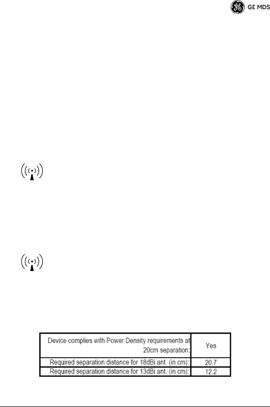
Professional installation required. The transceiver described here emits
radio frequency energy. Although the power level is low, the concentrated
energy from a directional antenna may pose a health hazard. Do not allow
people to come closer than 20.7 cm (8.15 inches) to the antenna when the
transmitter is operating. This calculation is based on an 18 dBi panel
antenna. Refer also to the table below, which lists required separation dis-
tances. Additional information on RF exposure is available on the Internet
at www.fcc.gov/oet/info/documents/bulletins.
To meet co-location requirements, the FCC requires a 20cm (7.87 inch)
separation distance between the unit’s WIFI and fundamental antenna
installations.
RF Exposure
(900 MHz models)
RF Exposure
(3650 MHz models)

vi
Mercury Reference Manual 05-4446A01, Rev. D
CSA/
us
Notice (Remote Transceiver Only)
This product is approved for use in Class 1, Division 2, Groups A, B, C & D Hazardous Locations. Such locations are
defined in Article 500 of the National Fire Protection Association (NFPA) publication
NFPA 70
, otherwise known as
the National Electrical Code.
The transceiver has been recognized for use in these hazardous locations by the Canadian Standards Association
(CSA) which also issues the US mark of approval (CSA/
US
). The CSA Certification is in accordance with CSA STD
C22.2 No. 213-M1987.
CSA Conditions of Approval: The transceiver is not acceptable as a stand-alone unit for use in the
hazardous locations described above. It must either be mounted within another piece of equipment
which is certified for hazardous locations, or installed within guidelines, or conditions of approval,
as set forth by the approving agencies. These conditions of approval are as follows:
The transceiver must be mounted within a separate enclosure which is suitable for the intended
application.
The antenna feedline, DC power cable and interface cable must be routed through conduit in accor-
dance with the National Electrical Code.
Installation, operation and maintenance of the transceiver should be in accordance with the trans-
ceiver's installation manual, and the National Electrical Code.
Tampering or replacement with non-factory components may adversely affect the safe use of the
transceiver in hazardous locations, and may void the approval.
A power connector with screw-type retaining screws as supplied by GE MDS must be used.
Do not disconnect equipment unless power has been switched off or the area is known to
be non-hazardous.
Refer to Articles 500 through 502 of the National Electrical Code (NFPA 70) for further
information on hazardous locations and approved Division 2 wiring methods.
FCC Part 15 Notices
The transceiver series complies with Part 15 of the FCC Rules. Operation is subject to the fol-
lowing two conditions: (1) this device may not cause harmful interference, and (2) this device must
accept any interference received, including interference that may cause undesired operation. This
device is specifically designed to be used under Section 15.247 of the FCC Rules and Regulations.
Any unauthorized modification or changes to this device without the express approval of Micro-
wave Data Systems may void the user’s authority to operate this device. Furthermore, the Mercury
Series is intended to be used only when installed in accordance with the instructions outlined in
this manual. Failure to comply with these instructions may also void the user’s authority to operate
this device.
Part 15 rules also require that the Effective Isotropic Radiated Power (EIRP) from a Mercury Series
installation not exceed 36 dBm. Refer to this manual for more information.
Industry Canada RSS Notices
Operation is subject to the following two conditions: (1) this device may not cause interference,
and (2) this device must accept any interference, including interference that may cause undesired
operation of the device.
EXPLOSION
HAZARD!

05-4446A01, Rev. D Mercury Reference Manual vii
To reduce potential radio interference to other users, the antenna type and its gain should be chosen
so that the Equivalent Isotropic Radiated Power (EIRP) is not more than that permitted for suc-
cessful communication.
This device has been designed to operate with the antennas listed on Page 170 and 171. Antennas
not included in this list are strictly prohibited for use with this device. The required antenna imped-
ance is 50 ohms.
Manual Revision and Accuracy
This manual was prepared to cover a specific version of firmware code. Accordingly, some screens
and features may differ from the actual unit you are working with. While every reasonable effort
has been made to ensure the accuracy of this guide, product improvements may also result in minor
differences between the manual and the product shipped to you. If you have additional questions
or need an exact specification for a product, please contact our Customer Service Team using the
information at the back of this guide. In addition, manual updates can often be found on the GE
MDS Web site at www.GEmds.com.
Environmental Information
The manufacture of this equipment has required the extraction and use of natural resources.
Improper disposal may contaminate the environment and present a health risk due to hazardous
substances contained within. To avoid dissemination of these substances into our environment, and
to limit the demand on natural resources, we encourage you to use the appropriate recycling sys-
tems for disposal. These systems will reuse or recycle most of the materials found in this equipment
in a sound way. Please contact GE MDS or your supplier for more information on the proper dis-
posal of this equipment.

viii
Mercury Reference Manual 05-4446A01, Rev. D

05-4446A01, Rev. D Mercury Reference Manual 1
1
PRODUCT OVERVIEW
AND APPLICATIONS
1 Chapter Counter Reset Paragraph
Contents
1.1 ABOUT THIS MANUAL ......................................................... 3
1.1.1 Start-Up Guide ....................................................................... 3
1.1.2 Online Access to Manuals ...................................................... 3
1.1.3 Conventions Used in This Manual ......................................... 3
1.2 PRODUCT DESCRIPTION ................................................... 4
1.2.1 Model Offerings ...................................................................... 6
1.2.2 Remote Radio with Option Set 1 ............................................ 7
1.2.3 GE MDS P23 Protected Network (Redundant) Config. ......... 8
1.2.4 External GPS PPS Option ..................................................... 9
1.3 APPLICATIONS ..................................................................... 9
1.3.1 Mobile/Fixed Data System ..................................................... 9
1.3.2 Wireless LAN ......................................................................... 10
1.3.3 Point-to-Point LAN Extension ................................................ 11
1.3.4 Serial Radio Network Connectivity ......................................... 11
1.3.5 Multiple Protocols and/or Services ......................................... 11
1.3.6 Wireless LAN with Mixed Services ......................................... 12
1.3.7 Upgrading Older Wireless Network with Serial Interfaces ..... 13
1.4 NETWORK DESIGN CONSIDERATIONS ............................ 14
1.4.1 Extending Network Coverage with Repeaters ....................... 14
1.4.2 Protected Network Operation using Multiple APs .................. 16
1.4.3 Collocating Multiple Radio Networks ..................................... 16
1.5 GE MDS CYBER SECURITY SUITE .................................... 17
1.6 ACCESSORIES ..................................................................... 19

2 Mercury Reference Manual 05-4446A01, Rev. D

05-4446A01, Rev. D Mercury Reference Manual 3
1.1 ABOUT THIS MANUAL
This
Reference Manual
is one of two publications provided for users of
the Mercury Series
TM
transceiver system. It contains detailed product
information, an overview of common applications, a screen-by-screen
review of the menu system, technical specifications, suggested settings
for various scenarios, and troubleshooting information. This manual
should be available to all personnel responsible for network design,
setup, commissioning and troubleshooting of the radios.
1.1.1 Start-Up Guide
The Mercury Series
Start-Up Guide
(Part No. 05-4558A01) is a com-
panion publication to the Reference Manual. It is a smaller book, with a
specific purpose—to guide an installer in the basic steps for getting a
transceiver on the air and communicating with other units in a network.
It provides only the essential information installers need for getting their
equipment up and running in the shortest time possible.
1.1.2 Online Access to Manuals
In addition to printed manuals, many users need access to documents
electronically. This is especially useful when you need to access docu-
mentation while traveling, or want to share a document with another
user in the field. Electronic documents also allow searching for a spe-
cific term or subject, especially in larger manuals.
Access manuals for our equipment anytime from our Web site at
www.GEmds.com
. Simply click the
Downloads
tab at the top of the home
page and select
Product Manuals
from the drop-down list. A search
window appears to help you locate the manual you need.
Online manuals are provided as PDF files in the Adobe
®
Acrobat
®
stan-
dard. If necessary, download the free reader for PDF files from
www.adobe.com
.
1.1.3 Conventions Used in This Manual
On-Screen Menu Items
On-screen menu items or command entries are presented in a distinctive
font to set them apart from regular text (for example:
Network Name, IP
Address, Password
). You will find this font most often in Chapter 3,
where the menu system is discussed in detail. When variable settings or
a range of options are available for a menu option, the items are pre-
sented inside brackets, with the default setting (if any) shown last after
a semicolon:
[
available settings or range;
default setting
]

4 Mercury Reference Manual 05-4446A01, Rev. D
Menu Strings
To help show the path to a menu selection, navigation strings are used
in several places in this manual. For example, suppose you want to view
or set the Network Name assigned to your system. This item is located
in the Network Configuration Menu, so the navigation string in the text
would appear as shown:
Main Menu>>Network Configuration>>Network Name
By following this order of menus, you can quickly reach the desired
menu.
1.2 PRODUCT DESCRIPTION
The GE MDS Mercury Series
TM
transceiver (Figure 1-1) is an
easy-to-install wireless solution offering extended range, secure opera-
tion, and multi-megabit performance in a compact and rugged package.
The transceiver is ideally suited for demanding applications in fixed or
mobile environments, where reliability and range are paramount.
The transceivers are commonly used to convey text documents,
graphics, e-mail, video, Voice over IP (VoIP), and a variety of other
application data between mobile, fixed-point, and WAN/LAN-based
entities.
Based on multi-carrier Orthogonal Frequency Division Multiplexing
(OFDM), the transceiver features high speed/low latency, basic Quality
of Service (QoS) for prioritizing traffic, Ethernet and serial encapsula-
tion, and network roaming. It also provides enhanced security features
including AES encryption and IEEE 802.1x Device Authentication,
making the Mercury system the best combination of security, range, and
speed of any industrial wireless solution on the market today.
Invisible place holder
Figure 1-1. The GE MDS
Mercury Series
TM
Transceiver
(Remote unit shown, AP similar in appearance)
Rugged Packaging
The transceivers are housed in a compact and rugged die cast-aluminum
case that need only be protected from direct exposure to the weather.

05-4446A01, Rev. D Mercury Reference Manual 5
This one enclosure contains all necessary components for radio opera-
tion and data communications.
Simple Installation
Mercury Transceivers are designed for rapid and trouble-free installa-
tion. For basic services, you simply connect the antennas (900 or 3650
MHz as required, and GPS), connect your data equipment, apply pri-
mary power, and set some operating parameters. No license is required
for 900 MHz operation in the USA, Canada, and many other countries.
A simple registration process is required for 3650 MHz operation in the
USA. Check requirements for your region before placing the equipment
into service.
Most installations employ an omni-directional antenna at the Access
Point (AP) location and mobile stations. Fixed Remote stations often
employ a directional antenna aimed at the AP. Regardless of the type
used, antennas are a vital part of the system and must be chosen and
installed correctly. Refer to
INSTALLATION PLANNING
on Page 161
for guidance on choosing suitable antennas and installation sites.
Secure Operation
Data network security is a vital issue in today’s wireless world. Mercury
transceivers
provide multiple tools to help you build a network that min-
imizes the risk of eavesdropping and unauthorized access. Some are
inherent in the radio’s operation, such as the use of 900 MHz
spread-spectrum transmissions; others include AES data encryption,
enabling/disabling channels, IEEE 802.1X port blocking, approved
device lists, secure devices management protocols, and password pro-
tection.
Security is not a one-step process that can simply be turned on and for-
gotten. It must be practiced and enforced at multiple levels,
24 hours-a-day and 7 days-a-week. See
“GE MDS CYBER SECURITY
SUITE”
on Page 17 for more information about the transceiver’s secu-
rity tools.
Robust Radio
Operation
The transceivers are designed for operation in the 900 MHz license-free
Industrial, Scientific, and Medical (ISM) band and the 3650-3700 MHz
registered band. They provide consistent, reliable coverage over a large
geographic area.
Mobile range depends on many factors, including terrain, building den-
sity, antenna gain, and speed of travel. The unit is designed for suc-
cessful application in a variety of mobile environments, and offers the
best combination of range, speed and robustness available in an indus-
trial wireless package today. By using multiple Access Points, a network
can be created that provides consistent, reliable coverage over a large
metropolitan area. See
“SPECIFICATIONS”
on Page 176 for more
information on transmission range.
Flexible Services
Users with a mix of equipment having Ethernet and serial data interfaces
can use this equipment via a Remote transceiver. The transceiver pro-
vides services in data networks that are migrating from legacy

6 Mercury Reference Manual 05-4446A01, Rev. D
serial/EIA-232-based hardware to the faster and more easily interfaced
Ethernet protocol.
Flexible
Management
You can locally or remotely configure, commission, troubleshoot, and
maintain the transceiver. Four different modes of access are available:
local RS-232 console terminal, local or remote IP access (via Telnet or
SSH), web browser (HTTP, HTTPS), and SNMP (v1/v2/v3) All IP
access interfaces are available through the unit’s wired Ethernet port and
over the air.
The text-based interfaces (RS-232 console, Telnet, and SSH) are imple-
mented in the form of easy-to-follow menus, and the terminal server
provides a wizard to help you configure the units correctly.
Transceiver
Features
The transceiver’s design makes the installation and configuration easy,
while allowing for future changes.
• Industrial-Grade Product—Extended temperature range for
trouble-free operation in extreme environments.
• Robust Radio Communications—Designed to operate over long
distances in dense, high-interference environments.
• Robust Network Security—Prevents common attack schemes
and hardware from gaining access or control of the network.
Common attack events are logged and reported by alarms.
• Transmission Speed—Operation at 1.5 Mbps is over 100-times
faster than 9.6 kbps radios.
• Plug-and-Play Connectivity—AP or Remote configuration
requires minimal setup.
• Built-in GPS Receiver—GPS technology is used for timing and
location data. The only external equipment needed for this func-
tionality is a GPS antenna available from GE MDS).
1.2.1 Model Offerings
The transceiver comes in two primary models—Access Point and
Remote. Unique hardware is used for each model. Of the Remote radios,
there are two sub-types available—
Standard Remote
and
Remote
with Option Set 1
, both of which support Ethernet and serial services.
Table 1-1 summarizes each radio’s interface services.
Table 1-1. Transceiver Models and Data Interface Services
Model Sub-Type Ethernet/LAN
1
COM1
1
USB Integrated WiFi
Access Point N/A
Yes Yes No No
Remote Standard Remote
Yes Yes No No
Remote w/Option 1 Set
Yes Yes Yes Yes
NOTES
1. COM1 provides access to the embedded Management System for all units.

05-4446A01, Rev. D Mercury Reference Manual 7
Available Frequency Bands
At the time of publication, Mercury transceivers are offered in two dif-
ferent frequency bands: 902-928 MHz (Mercury 900) and 3.65–3.70
GHz (Mercury 3650). The 900 MHz unit operates in a license-free spec-
trum (frequency hopping spread spectrum—FHSS), which may be used
by anyone in the USA, provided FCC Part 15 rules are observed.
Canada, and certain other countries allow license-free operation in this
band—check your country’s requirements.
The 3.65–3.70 GHz radio operates in a “registered” band using conten-
tion-based protocol, which provides additional protection from interfer-
ence, but it requires FCC registration before operation can begin. Other
restrictions may apply based on your location and “grandfathered” FSS
users. Check local requirements before operation. GE MDS has pub-
lished a whitepaper containing frequently asked questions about the
3.65–3.70 GHz band. To obtain a copy, request publication
05-4734A02.
Operationally, the Mercury 3650 has two key differences from the Mer-
cury 900: First, it operates on a different RF band (3.65–3.70 GHz).
Second, it only requires GPS for TDD synchronization of the Access
Points, which may or may not be needed for an installation.
Access Point or Remote?—Identification Tip
The outward appearance of AP and Remote radios is nearly identical,
however, the hardware for each type is different and they are
not
inter-
changeable. An quick way to identify them is to observe the color of the
gasket seal in the center of the radio case.
APs have a black gasket,
while Remote units have a yellow gasket.
In addition to gasket color, a label on the top of each radio identifies it
as an AP or Remote unit. If the label shows an
—A
suffix, it is an AP. If
it shows a
—R
suffix, it is a Remote.
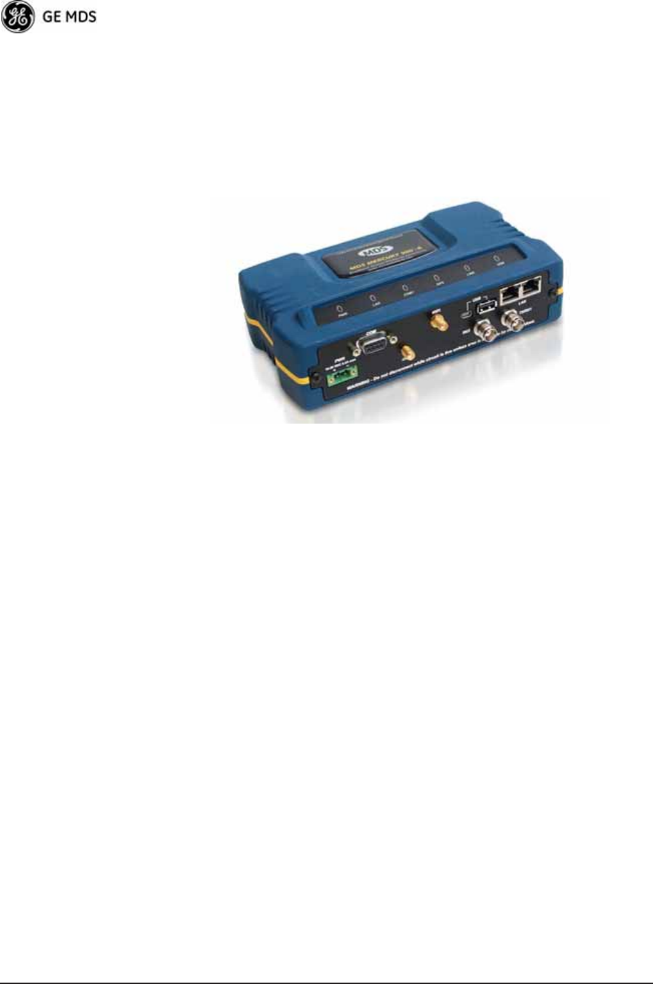
1.2.2 Remote Radio with Option Set 1
The “Option Set 1” Remote is similar to and compatible with the stan-
dard Mercury Remote. It contains the same 900 MHz radio, user inter-
face, and primary functionality as the Standard Remote. The Standard
Remote can be
directly replaced
with the Option Set 1 Remote. The key
differences are the additional physical interfaces: an IEEE 802.11b/g
WiFi networking module, a USB device port, a USB host port, and a
second Ethernet port on the radio enclosure.
The USB ports are used for device management. The host port accepts
a flash drive and can be used to transfer firmware and configuration
files. The two Ethernet ports are connected to an internal, integrated
switch and included in the Layer 2 bridge.
8 Mercury Reference Manual 05-4446A01, Rev. D
The internal WiFi module has FCC modular approval and may only be
operated by connecting one of the GE MDS approved antennas (see
802.11 WiFi Module Specifications
below) to the reverse-SMA con-
nector on the radio’s front panel. The WiFi module can operate as an
802.11 Access Point or Infrastructure Station, according to user config-
uration. The operational mode (
AP, Infrastructure RM
) and frequency can
be configured through the unit's user interface.
Invisible place holder
Figure 1-2. Mercury Remote with Option Set 1 (MaxRM)
(Note interface connector differences from Standard Remote)
802.11 WiFi Module Specifications
The specifications listed below are unique to Remotes with Option 1
Set, which contain a 2.4 GHz WiFi module.
SPECIFICATIONS
on
Page 176 contains a complete list of general Mercury Series specifica-
tions.
Protocol: IEEE 802.11b/g OFDM 6 to 54Mbps, CCK 1 to
11Mbps
Frequency Range: 2400 to 2500MHz
Maximum Transmit Power: 15 dBm
Permissible Antennas: PCTEL: BMLPV2400NGP
Sagrad: W1037
Sagrad: W1038
FCC: Part 15C
FCC ID: VRA-SG9011028
WiFi Antenna Connector: Female Reverse SMA
1.2.3 GE MDS P23 Protected Network (Redundant)
Configuration
For mission-critical applications, a Protected Network Station is also
offered. This unit incorporates two Access Points, two power supplies,
and a switchover logic board that automatically selects between Trans-
ceiver A and Transceiver B as the active radio. Figure 1-3 shows the

05-4446A01, Rev. D Mercury Reference Manual 9
protected chassis. For system-level information on this product, refer to
MDS publication 05-4161A01.
Invisible place holder
Figure 1-3. MDS P23 Protected Network Station
(incorporates two transceivers, with automatic switchover)
1.2.4 External GPS PPS Option
The External GPS Precise Positioning Service (PPS) option allows for
an external GPS device to provide the PPS input to the Mercury. This is
useful in installations where multiple radios require GPS timing. This
option prevents each Mercury from requiring its own GPS antenna.
Refer to the electrical specifications in the
External GPS PPS Option
section on Page 178. This option is only available in hardware revision
1.0.2 or later.
1.3 APPLICATIONS
The following sections provide illustrations of typical transceiver instal-
lations. This is an overview only. A Network Administrator should be
involved in all installation planning activities.
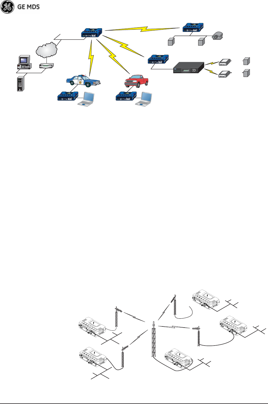
1.3.1 Mobile/Fixed Data System
Mercury transceivers support high-speed data communications in a
mobile environment. In this application, Remote radios “roam” between
different Access Points, providing seamless transitions and continuous
coverage throughout a municipal area. Figure 1-4 shows an example of
an integrated system employing both mobile and fixed Mercury trans-
ceivers.
10 Mercury Reference Manual 05-4446A01, Rev. D
Invisible place holder
Figure 1-4. Integrated Mobile/Fixed Application
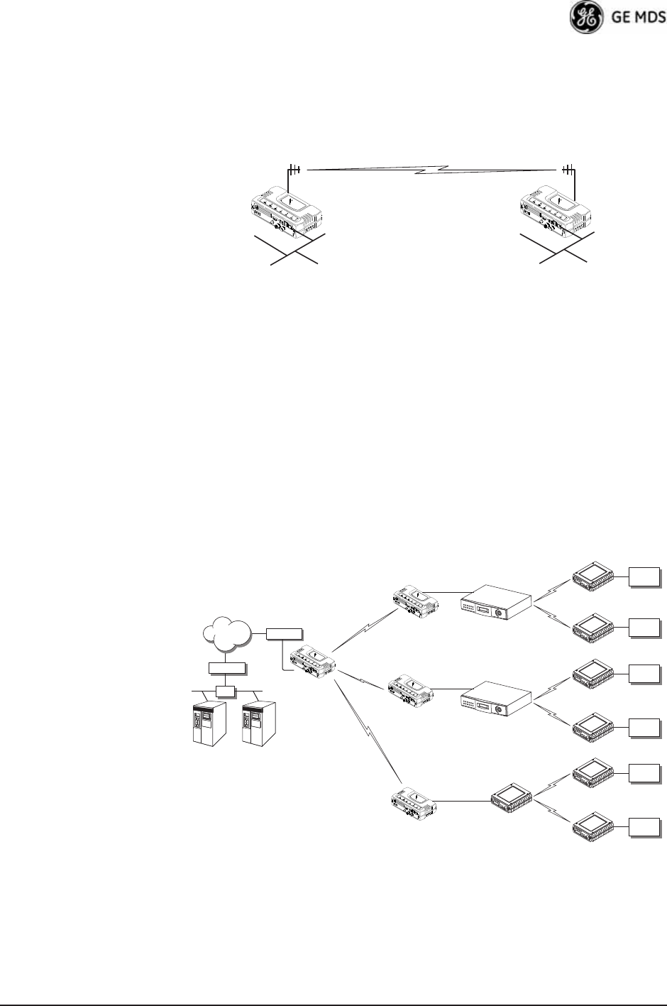
1.3.2 Wireless LAN
The wireless LAN is a common application of the transceiver. It consists
of a central control station (Access Point) and one or more associated
Remote units, as shown in Figure 1-5. A LAN provides communications
between a central WAN/LAN and remote Ethernet segments. The oper-
ation of the radio system is transparent to the computer equipment con-
nected to the transceiver.
The Access Point is positioned at a location from which it communi-
cates with all Remote units in the system. Commonly, this is a high loca-
tion on top of a building or communications tower. Messages are
exchanged at the Ethernet level. This includes all types of IP traffic.
A Remote transceiver can only communicate over-the-air to an Access
Point (AP). Peer-to-peer communications between Remotes can only
take place indirectly via the AP. In the same fashion, an AP can only
communicate over-the-air to associated Remote units. Exception: Two
APs can communicate with each other “off-the-air” through their
Ethernet connectors using a common LAN/WAN.
Invisible place holder
Figure 1-5. Typical Wireless LAN
MDS 4790
Master Radio
Licensed Serial/IP Integration
Mercury AP
MDS 4710
RTU/PLC
(Serial)
RS-232
RS-232
RS-232
MDS 4710
RTU/PLC
(Serial)
RTU/PLC
(Ethernet)
Long Range WLAN
Mobile DataMobile Data
MDS NETview MS®
Server
(Ethernet)
Computer Router
WAN
Video
Surveillance
Mercury
remote
Control Center Mercury
remote
Mercury
remote
Mercury
remote
R
emo
t
e
Remote
Access Point
Remote
Remote
LAN
LAN
WAN/LAN
LAN
LAN
05-4446A01, Rev. D Mercury Reference Manual 11
1.3.3 Point-to-Point LAN Extension
A point-to-point configuration (Figure 1-6) is a simple arrangement
consisting of an Access Point and a Remote unit. This provides a com-
munications link for transferring data between two locations.
Invisible place holder
Figure 1-6. Typical Point-to-Point Link
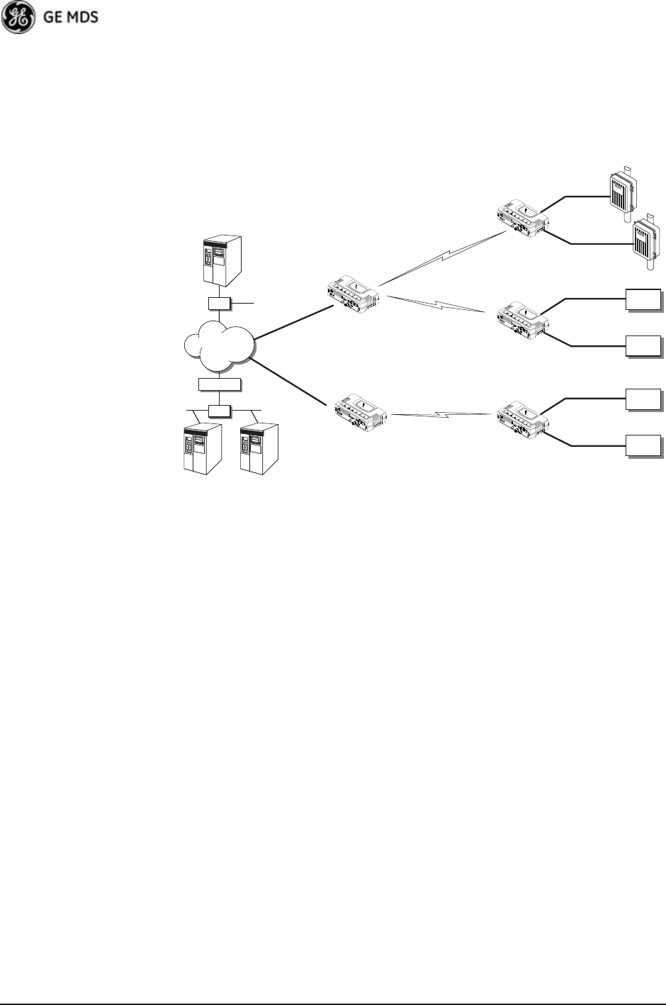
1.3.4 Serial Radio Network Connectivity
The transceiver provides a path for serial devices to migrate to
IP/Ethernet systems. Many radio networks in operation today still rely
on serial networks at data rates of 9600 bps or less. These networks can
use the transceiver as a means to continue using the serial service, while
allowing the infrastructure to migrate to an IP format.
A Remote transceiver with its serial port connected to a GE MDS
serial-based radio, such as the MDS x790/x710, MDS TransNET and
others, provides a path for bringing the data from the older radio into the
IP/Ethernet environment of a Mercury-based system.
Invisible place holder
Figure 1-7. Backhaul Network
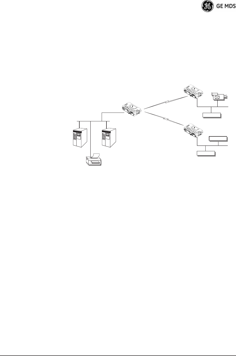
1.3.5 Multiple Protocols and/or Services
Prior to the introduction of Ethernet/IP-based radios, two radios were
often used to service two different types of devices (typically connected
LAN/WAN
Access Point Remote
LAN
MDS 4790
Master
MDS 9790
Master
MDS 9810
Master
Serial Conn.
Serial Conn.
Serial Conn.
MDS 4710 Remote
NMS Control
Point
SCADA Host
Modbus/IP
HUB Access Point
MDS 4710 Remote
MDS 9710 Remote
MDS 9710 Remote
MDS 9810 Remote
MDS 9810 Remote
Remote Serial
Remote Serial
Remote Serial
NETWORK
ROUTER
ROUTER
Serial
Device
Serial
Device
Serial
Device
Serial
Device
Serial
Device
Serial
Device
12 Mercury Reference Manual 05-4446A01, Rev. D
to different SCADA hosts). A Mercury radio provides this capability
using a single remote unit. The unit’s serial port can be connected via IP
to different SCADA hosts, transporting different (or the same) proto-
cols. Both data streams are completely independent, and the transceiver
provides seamless simultaneous operation as shown in Figure 1-8.
Invisible place holder
Figure 1-8. Multiple Protocol Network
By using a single radio, the cost of deployment is cut in half. Beyond
requiring only one radio instead of two, the biggest cost reduction comes
from using half of the required infrastructure at the remote site: one
antenna, one feedline, one lightning protector and ancillary hardware.
Other cost reductions come from the system as a whole, such as reduced
management requirements. And above all, the radio provides the poten-
tial for future applications that run over Ethernet and IP, such as video
for remote surveillance.
1.3.6 Wireless LAN with Mixed Services
The transceiver is an excellent solution for a long-range industrial wire-
less LAN. It offers several advantages over commercial solutions, pri-
marily improved performance over extended distances. The rugged
construction of the radio and its extended temperature range make it an
ideal solution even in harsh locations. In extreme environments, a
simple NEMA enclosure is sufficient to house the unit.
The transceiver trades higher speed for longer range. Commercial
802.11a/b/g solutions are designed to provide service to relatively small
areas such as offices, warehouses and homes. They provide high data
rates but have limited range. The Mercury transmits at a higher power
level, uses a different frequency band, has higher sensitivity, and a nar-
NETview SCADA Host
Total Flow
Access Point
Remote Serial
Remote Serial
SCADA Host
Modbus/IP
Remote Serial
Access Point
RTU
Flow Meter
EIA-232
EIA-232
EIA-232
EIA-232
EIA-232
EIA-232
ROUTER
HUB
Serial
Device
Serial
Device
Serial
Device
Serial
Device
HUB
HUB
HUB
WAN
05-4446A01, Rev. D Mercury Reference Manual 13
rower channel to concentrate the radio energy, reaching farther dis-
tances. It is designed for industrial operation from the ground up.
IP-based devices that may be used with the transceiver include new,
powerful Remote Terminal Units (RTUs) and Programmable Logic
Controllers (PLCs). These, as well as other devices, may be used in
applications ranging from SCADA/telemetry monitoring, web-based
video, security monitoring, and Voice over IP. Figure 1-9 shows a typ-
ical wireless IP network.
Invisible place holder
Figure 1-9. Extended-Range LAN with Mixed Applications
1.3.7 Upgrading Older Wireless Network with Serial
Interfaces
Millions of wireless data products have been installed in the last two
decades for licensed and license-free operation, many of them manufac-
tured by GE MDS. There are several ways that these systems can benefit
from incorporating Mercury equipment. The chief advantages are inter-
face flexibility (serial and Ethernet in one unit), and higher data
throughput. By taking advantage of its built-in serial and Ethernet inter-
faces, the transceiver is well suited to replace leased lines, dial-up lines,
or existing “multiple address” data transceivers.
Replacing Legacy Wireless Products
In most cases, legacy radio transceivers supporting serial-interface
equipment can be replaced with Mercury transceivers. Legacy equip-
ment can be connected to the transceiver through the COM1 port with a
DB-25 to DB-9 cable wired for EIA-232 signaling. The COM1 port acts
as a Data Communications Equipment (DCE) port.
NMS Control
Point
SCADA Host
Modbus/IP
Access Point
Remote Bridge
Printer
IP/Ethernet
IP/Ethernet
Remote Bridge
IP/Ethernet
IP Camera
14 Mercury Reference Manual 05-4446A01, Rev. D
NOTE: Several previous GE MDS-brand products had non-standard
signal lines on their interface connectors (for example, to
control sleep functions and alarm lines). These special func-
tions are not provided nor supported by the Mercury trans-
ceiver. Consult equipment manuals for complete pinout
information.
1.4 NETWORK DESIGN
CONSIDERATIONS
1.4.1 Extending Network Coverage with Repeaters
What is a Repeater System?
A repeater works by re-transmitting data from outlying remote sites to
the Access Point, and vice-versa. It introduces some additional
end-to-end transmission delay but provides longer-range connectivity.
In some geographical areas, obstacles can make communications diffi-
cult. These obstacles are commonly large buildings, hills, or dense
foliage. These obstacles can often be overcome with a repeater station.
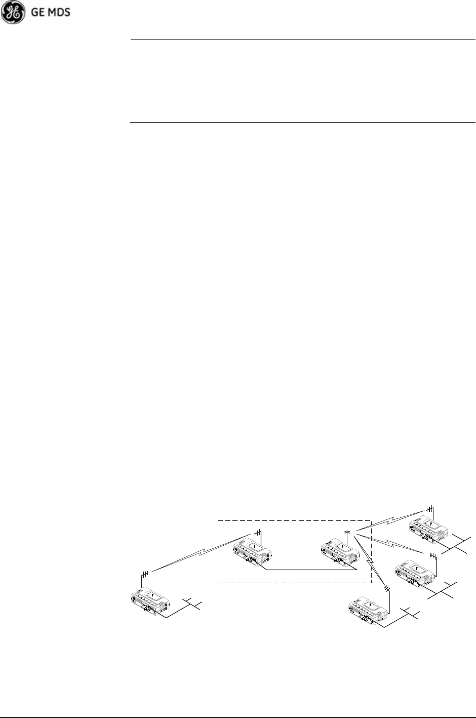
Option A—Using two transceivers to form a repeater station
(back-to-back repeater)
Although the range between fixed transceivers can be up to 40 km (25
miles) over favorable terrain, it is possible to extend the range consider-
ably by connecting two units together at one site in a “back-to-back”
fashion, creating repeater as shown in Figure 1-10. Use this arrangement
whenever the objective is to utilize the maximum range between sta-
tions. In this case, using high-gain Yagi antennas at each location pro-
vides more reliable communications than their counterparts—
omnidirectional antennas.
Invisible place holder
Figure 1-10. Typical LAN with a Repeater Link
Overview Two transceivers may be connected “back-to-back” through the LAN
ports to form a repeater station. If the transceivers are connected directly
to each other, you must use an Ethernet cross-over cable. This configu-
Remote
Remote
Remote
Remote
Access
Point
Access
Point
LAN/WAN
REPEATER
Crossover Cable
LAN
LAN
LAN
Ethernet
POINT-TO-POINT LINK

05-4446A01, Rev. D Mercury Reference Manual 15
ration is sometimes required in a network that includes a distant Remote
that would otherwise be unable to communicate directly with the Access
Point station due to distance or terrain.
The geographic location of a repeater station is especially important.
Choose a site that allows good communication with both the Access
Point and the outlying Remote site. This is often on top of a hill,
building, or other elevated terrain from which both sites can be “seen”
by the repeater station antennas. A detailed discussion on the effects of
terrain is given in Section 5.1.2, Site Selection (beginning on Page 162).
The following paragraphs contain specific requirements for repeater
systems.
Antennas Two antennas are required at this type of repeater station—one for each
radio. You must take measures to minimize the chance of interference
between these antennas. One effective technique for limiting interfer-
ence is to employ vertical separation. In this arrangement, assuming
both antennas are vertically polarized, one antenna is mounted directly
over the other, separated by at least 10 feet (3 meters). This takes advan-
tage of the minimal radiation exhibited by most antennas directly above
and below their driven elements.
Another interference reduction technique is to cross-polarize the
repeater antennas. If one antenna is mounted for polarization in the ver-
tical plane, and the other in the horizontal plane, an additional 20 dB of
attenuation is achieved. The corresponding stations should use the same
antenna orientation when cross-polarization is used.
Network Name The two radios that are wired together at the repeater site must have dif-
ferent network names. For information on how to set or view the net-
work names, see “STEP 3—CONNECT PC TO THE TRANSCEIVER”
on Page 25.
TDD Sync Mode To avoid interference between the two APs that form a repeater station,
they should be synchronized so that they will transmit at the same time
and receive at the same time. This eliminates the possibility of one AP
transmitting while another is trying to receive.
This can be accomplished by setting the TDD Sync Mode parameter in the
Frequency Configuration menu to GPS Required. See Frequency Control
Menu on Page 65 for details.
Option B—Using the AP as a Store-and-Forward Packet
Repeater
You can extend a wireless network by using the Access Point as a
repeater to re-transmit the signals of all stations in the network. (See
Figure 1-11 on Page 16.)

16 Mercury Reference Manual 05-4446A01, Rev. D
Invisible place holder
Figure 1-11. Typical Store-and-Forward Repeater Arrangement
As with the conventional repeater described in Option 1 above, the loca-
tion of a store and forward repeater is also important. A site must be
chosen that allows good communication with both the Access Point and
the outlying Remote site. This can be on the top of a hill, building, or
other elevated terrain from which all sites can be “seen” by the repeater
station antenna. A detailed discussion on the effects of terrain is given
in Section 5.1.2, Site Selection (beginning on Page 162).
1.4.2 Protected Network Operation using Multiple
APs
Although GE MDS transceivers have a very robust design and have
undergone intensive testing before being shipped, it is possible for iso-
lated failures to occur. In mission-critical applications, down time can
be virtually eliminated by using some, or all, of the following configu-
rations:
In a point-to-multipoint scenario, the Access Point services multiple
remotes. A problem in the Access Point will have an effect on all
remotes, since none will have access to the network. When operation of
the network does not tolerate any down time, it is possible to set up a
protected configuration for the Access Point to greatly reduce the possi-
bility of this occurrence.
Two or more Access Points can be configured identically, each with its
own independent antenna. In this scenario, Remotes will associate with
one of the available Access Points. In case of a failure of that AP, the
Remotes will quickly associate with another Access Point, re-estab-
lishing connectivity to the end devices. Because only one Access Point
operates at any given time, collisions between APs is not possible.
1.4.3 Collocating Multiple Radio Networks
Many networks can operate in relatively close physical proximity to one
another provided reasonable measures are taken to assure the radio
signal of one Access Point is not directed at the antenna of the second
Access Point.
Remote
Remote
Remote
Remote
Access Point
LAN/WAN
REPEATER
LAN
LAN
LAN

05-4446A01, Rev. D Mercury Reference Manual 17
The Network Name and the Association Process
The Network Name is the foundation for building individual radio net-
works. Remotes in a network with the same network name as an Access
Point (AP) unit are “associated” with that AP.
The use of a different Network Name does not guarantee an interfer-
ence-free system. It does, however, assure that only data destined for a
unique network is passed through to that network.
Co-Location for
Multiple Networks It may be desirable to co-locate Access Points at one location to take
advantage of an excellent location that can serve two independent net-
works. Configure each network with a unique Network Name, and
install each AP’s antenna with at least 10 feet of vertical separation to
minimize RFI.
To co-locate APs, configure them with Time Division Duplex (TDD)
Sync set to GPS Required. Configure all APs that are within range of each
other with the same pattern, but with a unique Hop Pattern Offset. For
more information, see “Frequency Control Menu” on Page 65.
NOTE: Transceivers are shipped with the Network Name set to
MDS-Mercury as a factory default.
Can radio frequency interference (RFI) disrupt my wireless
network?
When multiple radio networks operate in close physical proximity to
other wireless networks, individual units may not operate reliably under
weak signal conditions and may be influenced by strong radio signals on
adjacent bands. This radio frequency interference cannot be predicted
with certainty, and can only be determined by experimentation. If you
need to co-locate two units, start by using the largest possible vertical
antenna separation between the two AP antennas on the same support
structure. If that does not work, consult with your factory representative
about other techniques for controlling radio frequency interference
between the radios. (See “A Word About Radio Interference” on
Page 168 for more details.)
1.5 GE MDS CYBER SECURITY SUITE
Today, the operation and management of an enterprise is increasingly
dependent on electronic information flow. An accompanying concern
becomes the cyber security of the communication infrastructure and the
security of the data itself.

18 Mercury Reference Manual 05-4446A01, Rev. D
The transceiver is capable of dealing with many common security
issues. Table 1-2 profiles security risks and how the transceiver pro-
vides a solution for minimizing vulnerability.
Table 1-2. Security Risk Management
Security Vulnerability GE MDS Cyber Security Solution
Unauthorized access to the backbone
network through a foreign remote radio • IEEE 802.1x device authentication
• Approved Remotes List (local)
Only those remotes included in the
AP list will associate
“Rogue” AP, where a foreign AP takes
control of some or all remote radios and
thus remote devices
• IEEE 802.1x device authentication
• Approved AP List
A remote will only associate to those
APs included in its local authorized
list of APs
Dictionary attacks, where a hacker runs a
program that sequentially tries to break a
password.
• Failed-login lockdown
After five tries, the transceiver
ignores login requests for 5 minutes.
Critical event reports (traps) are
generated as well.
Denial of service, where Remote radios
could be reconfigured with bad
parameters, bringing the network down.
• Remote login with SSH or HTTPS
• Local console login
• Disabled HTTP and Telnet to allow
only local management services
Airsnort and other war-driving hackers in
parking lots, etc. • Operation is not interoperable with
standard 802.11 wireless cards
• The transceiver cannot be put in a
promiscuous mode
• Proprietary data framing
Eavesdropping, intercepting messages • AES-128 encryption
Unprotected access to configuration via
SNMPv1 • Implement SNMPv3 secure
operation
Intrusion detection •Provides early warning via SNMP
through critical event reports
(unauthorized, logging attempts,
etc.)
•Unauthorized AP MAC address
detected at Remote
•Unauthorized Remote MAC
address detected at AP
•Login attempt limit exceeded
(Accessed via: Telnet, HTTP, or
local)
•Successful login/logout
(Accessed via: Telnet, HTTP, or
local)

05-4446A01, Rev. D Mercury Reference Manual 19
1.6 ACCESSORIES
The transceiver can be used with one or more of the accessories listed in
Table 1-3. Contact the factory for ordering details.
Table 1-3. Accessories
Accessory Description GE MDS
Part No.
AC Power
Adapter Kit
A small power supply module designed for
continuous service. UL approved. Input:
120/220; Output: 13.8 Vdc @ 2.5 A
01-3682A02
Omni-
Directional
Antennas
Rugged antennas well suited for use at Access
Point installations. Consult with your factory
Sales Representative for details
--
Yagi Antenna
(Directional)
Rugged antennas well suited for use at fixed
Remote sites. Consult with your factory Sales
Representative for details.
--
GPS Receiving
Antennas
A variety of fixed and mobile GPS antennas
(active and passive) are available. Consult with
your factory Sales Representative for details.
--
TNC Male-to-N
Female Adapter
One-piece RF adaptor plug. 97-1677A161
TNC Male-to-N
Female Adapter
Cable
Short length of coaxial cable used to connect
the radio’s TNC antenna connector to a Type N
commonly used on large diameter coaxial
cables.
97-1677A159
(3 ft./1m)
97-1677A160
(6 ft./1.8m)
Ethernet RJ-45
Crossover
Cable (CAT5)
Cable assembly used to cross-connect the
Ethernet ports of two transceivers used in a
repeater configuration.
(Cable length ≈ 3 ft./1M)
97-1870A21
2-Pin Power
Plug
Mates with power connector on transceiver.
Screw terminals provided for wires, threaded
locking screws to prevent accidental disconnect.
73-1194A39
Ethernet RJ-45
Straight-thru
Cable (CAT5)
Cable assembly used to connect an Ethernet
device to the transceiver. Both ends of the cable
are wired identically.
(Cable length ≈ 3 ft./1M)
97-1870A20
EIA-232
Shielded Data
Cable
Shielded cable terminated with a DB-25 male
connector on one end, and a DB-9 female on the
other end. Two lengths available (see part
numbers at right).
97-3035L06
(6 ft./1.8m)
97-3035L15
(15 ft./4.6m)
EIA-232
Shielded Data
Cable
Shielded cable terminated with a DB-9 male
connector on one end, and a DB-9 female on the
other end, 6 ft./1.8m long.
97-1971A03
Flat-Surface
Mounting
Brackets &
Screws
Brackets: 2˝ x 3˝ plates designed to be screwed
onto the bottom of the unit for surface-mounting
the radio.
82-1753-A01
Bracket screws: 6-32/1/4˝ with locking adhesive.
(Industry Standard MS 51957-26)
70-2620-A01
Fuse Internal fuse, 5.0 Ampere 29-1784A04

20 Mercury Reference Manual 05-4446A01, Rev. D
DIN Rail
Mounting
Bracket
Bracket used to mount the transceiver to
standard 35 mm DIN rails commonly found in
equipment cabinets and panels.
03-4022A03
COM1 Interface
Adapter
DB-25(F) to DB-9(M) shielded cable assembly
(6 ft./1.8 m) for connection of equipment or other
EIA-232 serial devices previously connected to
“legacy” units. (Consult factory for other lengths
and variations.)
97-3035A06
Bandpass Filter Antenna system filter that helps eliminate
interference from nearby paging transmitters.
20-2822A02
Ethernet Surge
Suppressor
Surge suppressor for protection of Ethernet port
against lightning.
29-4018A01
Table 1-3. Accessories (Continued)
Accessory Description GE MDS
Part No.

05-4446A01, Rev. D Mercury Reference Manual 21
2TABLETOP EVALUATION
AND TEST SETUP
2 Chapter Counter Reset Paragraph
Contents
2.1 OVERVIEW ........................................................................... 23
2.2 STEP 1—CONNECT THE ANTENNA PORTS...................... 23
2.3 STEP 2—CONNECT THE PRIMARY POWER ..................... 24
2.4 STEP 3—CONNECT PC TO THE TRANSCEIVER............... 25
2.5 STEP 4—REVIEW TRANSCEIVER CONFIGURATION ....... 25
2.5.1 Getting Started ....................................................................... 25
2.5.2 Procedure ............................................................................... 25
2.5.3 Basic Configuration Defaults .................................................. 25
2.6 STEP 5—CONNECT LAN OR SERIAL DATA EQUIPMENT. 26
2.6.1 Option 1 Set (MaxRM) Connectors ........................................ 28
2.7 STEP 6—CHECK FOR NORMAL OPERATION ................... 29

22 Mercury Reference Manual 05-4446A01, Rev. D
05-4446A01, Rev. D Mercury Reference Manual 23
2.1 OVERVIEW
GE MDS recommends that you set up a “tabletop network” to verify the
basic operation of the transceivers. This allows experimenting with net-
work designs, configurations, or network equipment in a convenient
location. This test can be performed with any number of radios.
When you are satisfied that the network is functioning properly in a
benchtop setting, perform the field installation. Complete information
for field installation, including mounting dimensions and antenna selec-
tion, is provided in INSTALLATION PLANNING on Page 161.
NOTE: It is important to use a “Network Name” that is different from
any currently in use in your area during the testing period.
To simulate data traffic over the radio network, connect a PC or LAN to
the Ethernet port of the Access Point and PING each transceiver several
times.
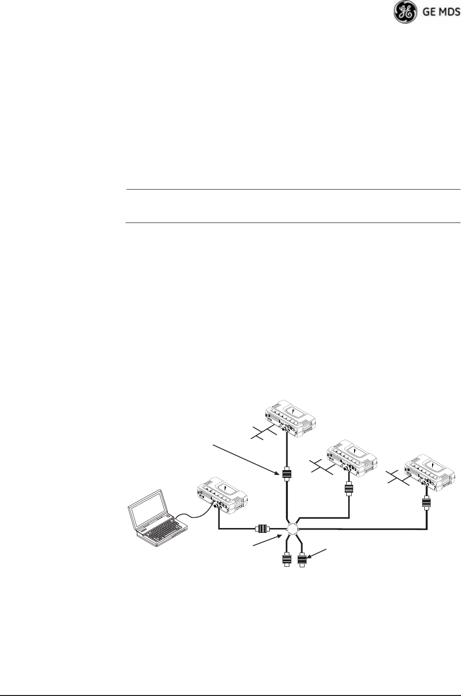
2.2 STEP 1—CONNECT THE ANTENNA
PORTS
Figure 2-1 shows the tabletop arrangement. Connect the antenna ports
of each transceiver as shown. This provides stable radio communica-
tions between each unit and prevents interference to nearby electronic
equipment.
Invisible place holder
Figure 2-1. Typical Setup for Tabletop-Testing of Radios
POWER ATTENUATORS
• Fixed or adjustable
• 2W Minimum Rating
POWER DIVIDER
NON-RADIATING ATTENUATORS
• Install on unused divider ports (if any)
• 2W Minimum Rating
COMPUTER
Remote
Remote
Access Point
Remote
24 Mercury Reference Manual 05-4446A01, Rev. D
NOTE: Use attenuation between all units in the test setup. The amount
of attenuation required depends on the number of units tested
and the desired signal strength (RSSI) at each transceiver
during the test. In no case should a signal greater than –50 dBm
be applied to any transceiver in the test setup. GE MDS recom-
mends an RF power output level of +20 dBm from the AP.
Remote power is not setable. (See “Radio Configuration
Menu” on Page 63.)
2.3 STEP 2—CONNECT THE PRIMARY
POWER
The primary power at the transceiver’s power connector must be within
10.5–30 Vdc and be capable of continuously providing 30 Watts. Typ-
ical power consumption for 13.8 Vdc and 24 Vdc operation are listed in
SPECIFICATIONS on Page 176.
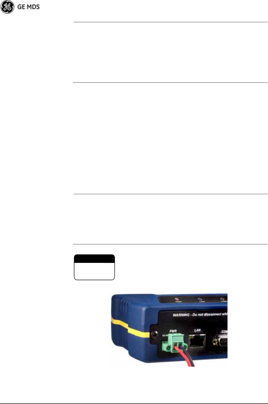
A Phoenix two-pole power connector with screw-terminals is provided
with each unit. Strip the wire leads to 6 mm (0.25"). Be sure to observe
proper polarity with the positive lead (+) on the left and negative (–) on
the right, as shown in Figure 2-2.
NOTE: The transceiver typically requires about 30 seconds to power up, and
might require several minutes to associate with another unit, if GPS
is required for time synchronization.
GPS is required for all configurations except when “Free Run”
single-channel (non-frequency hopping) operation is used, which
might be possible in some low-interference environments.
Only use the transceiver with negative-ground power
systems. Make sure the polarity of the power source
is correct.
Invisible place holder
Figure 2-2. Power Connector
(Polarity: Left +, Right —)
CAUTION
POSSIBLE
EQUIPMENT
DAMAGE

05-4446A01, Rev. D Mercury Reference Manual 25
2.4 STEP 3—CONNECT PC TO THE
TRANSCEIVER
Connect a PC’s Ethernet port to the LAN port using an Ethernet cross-
over cable. The LAN LED should light. Alternatively, you can use a
serial cable to connect to the COM1 port (Figure 2-3 on Page 27).
2.5 STEP 4—REVIEW TRANSCEIVER
CONFIGURATION
2.5.1 Getting Started
Start by logging into the Access Point radio. This is done first because
the Remotes are dependent on the AP’s beacon signal to achieve an
“associated” state.
Once the Access Point is up and running, move the computer connection
to each of the Remote units, log-in at each unit, review their configura-
tion, set their IP addresses, Network Name, and frequency configura-
tion, then wait for each AP to achieve an associated state.
With all units associated, you will be ready to connect and test your data
services.
2.5.2 Procedure
The following is a summary of the configuration procedure that must be
done on each unit in the system. Key parameters are shown on the
Embedded Management System overview (Figure 3-1 on Page 34). A
lists of parameters is located in two tables—Table 4-5 on Page 152 and
Table 4-7 on Page 154. Detailed information on using the Management
System can be found in INTRODUCTION on Page 33.
NOTE: The Management System supports the use of “configuration
files” to help consistently configure multiple units. These are
explained in Configuration Scripts Menu on Page 130.
2.5.3 Basic Configuration Defaults
Table 2-1 provides a selection of key operating parameters, their range,
and default values. All of these are accessible through a terminal emu-
lator connected to the COM1 serial port or through a Web browser con-
nected to the LAN port (see Figure 5-1 on Page 161 for hookup).
NOTE: Access to the transceiver’s Management System and changes
to all parameters requires entering a security password.

26 Mercury Reference Manual 05-4446A01, Rev. D
For benchtop evaluation, configure:
•Frequency Mode = Single Channel
•Single Frequency Channel = 0
•RF Bandwidth = 1.75
•TDD Sync = Free Run
For more information on configuring these parameters, see “Frequency
Control Menu” on Page 65.
A unique IP address and subnet are required to access all IP-based man-
agement interfaces (telnet, SSH, SNMP, and Web), either through the
LAN port or remotely over-the-air.
2.6 STEP 5—CONNECT LAN OR
SERIAL DATA EQUIPMENT
Connect a local area network to the LAN port or a serial device to the
COM1 (DCE) port. The LAN port supports any Ethernet-compatible
equipment. This includes devices that use Internet Protocol (IP).
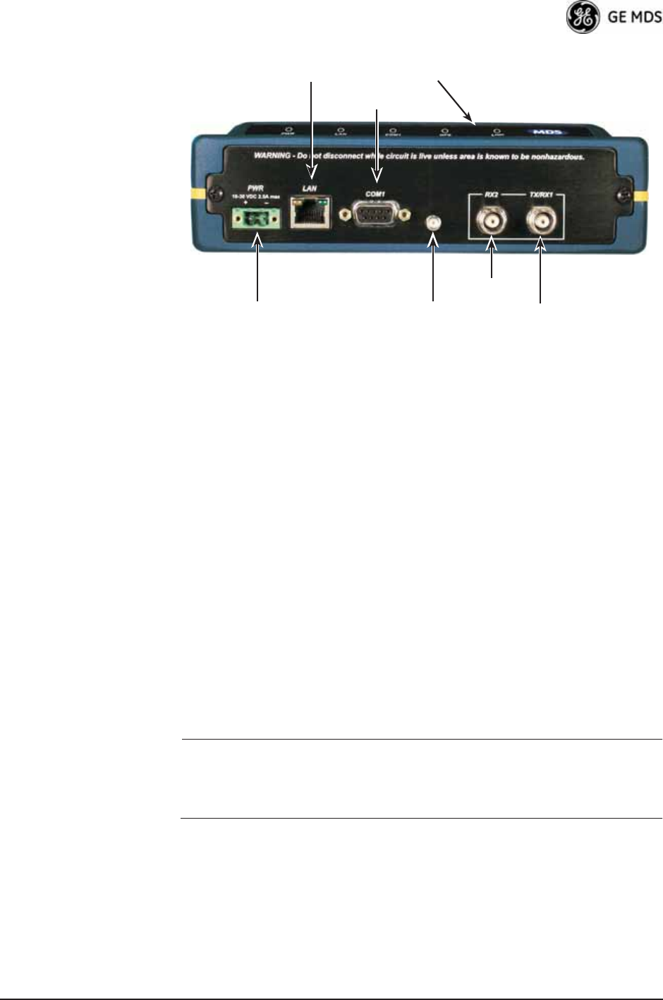
Figure 2-3 on Page 27 shows the interface connectors on the front panel
of the standard transceiver (Remote). The Option 1 Set Remote connec-
tors are shown in Figure 2-4 on Page 28.
NOTE: The use of shielded Ethernet cable is recommended for
connection to the radio’s ETH port. The radio meets regulatory
emission standards without shielded cable, but shielding
reduces the possibility of interference in sensitive environ-
ments, and is in keeping with good engineering practice.
Table 2-1. Basic Configuration Defaults
Item Menu Location Default Values/Range
Network Name Main Menu>>
Radio Configuration>>
Network Name
MDS-Mercury • 1–15 alphanumeric
characters
• Case-sensitive;
can be mixed case
IP Address Main Menu>>
Network Configuration>>
IP Address
192.168.1.1 Contact your network
administrator
RF Output
Power
Main Menu>>
Radio Configuration>>
Transmit Power
+29 dBm (900 model)
+23 dBm (3650 model)
AP: -30 to +29 dBm
RM: 0 to +29 dBm
Unit Password Main Menu>>
Device Information>>
User Password
admin
(lower case)
• 1–13 alphanumeric
characters
• Case-sensitive;
can be mixed case
05-4446A01, Rev. D Mercury Reference Manual 27
Invisible place holder
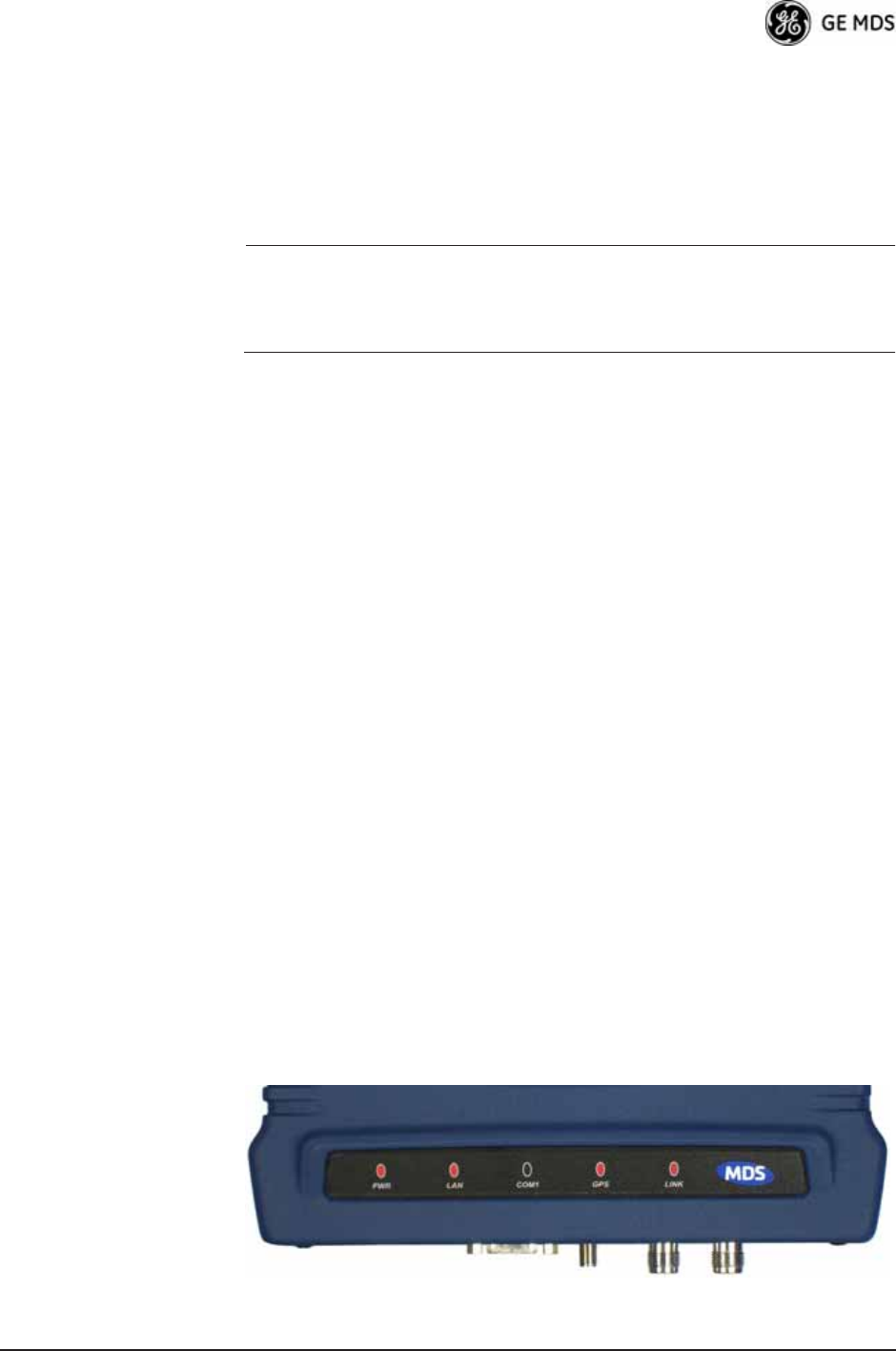
Figure 2-3. Transceiver Interface Connectors
(Standard unit shown; See Figure 2-4 on Page 28 for MaxRM unit)
•LED INDICATOR PANEL—Displays the basic operating status of
the transceiver. See section 2.7 on Page 29 for detailed informa-
tion.
•COM1 SERIAL PORT— DB-9 connector used for management
of the transceiver with a connected PC. INTRODUCTION on
Page 33 provides complete connection details.
•LAN PORT—Connection point for Ethernet Local Area Net-
work. The connector has integrated LEDs to indicate signal
activity as follows: A steady green LED indicates that a link has
been achieved; a flashing green LED indicates data activity; and
a yellow LED indicates 100 Mbps operation.
•PWR— DC power connection for the transceiver. Power source
must be 10 Vdc to 30 Vdc, negative ground, and capable of pro-
viding at least 25 watts.
•GPS ANTENNA PORT— Coaxial connector (SMA-type) for
connection of a GPS receiving antenna. Provides 3.5 Vdc output
for compatibility with powered (active) GPS antennas. The GPS
receiving antenna’s gain must be 16 dBi or less.
NOTE: GPS functionality is required on all Access Points and
Remotes except when “Free Run” single-channel (non-frequency
hopping) operation is used, which might be possible in some
low-interference environments.
•RX2 ANTENNA PORT— Coaxial connector (TNC-type) for
attachment of a second receiving antenna used in space diver-
sity arrangements.
•TX/RX1 ANTENNA PORT— Coaxial connector (TNC-type) for
attachment of the main station antenna (transmit and receive).
COM1
SERIAL PORT
LAN PORT
GPS ANTENNA
CONNECTION
RX2 ANTENNA
PORT
TX/RX1
ANTENNA PORT
DC POWER INPUT
(10—30 VDC, 2.5A)
LED INDICATOR
PANEL
28 Mercury Reference Manual 05-4446A01, Rev. D
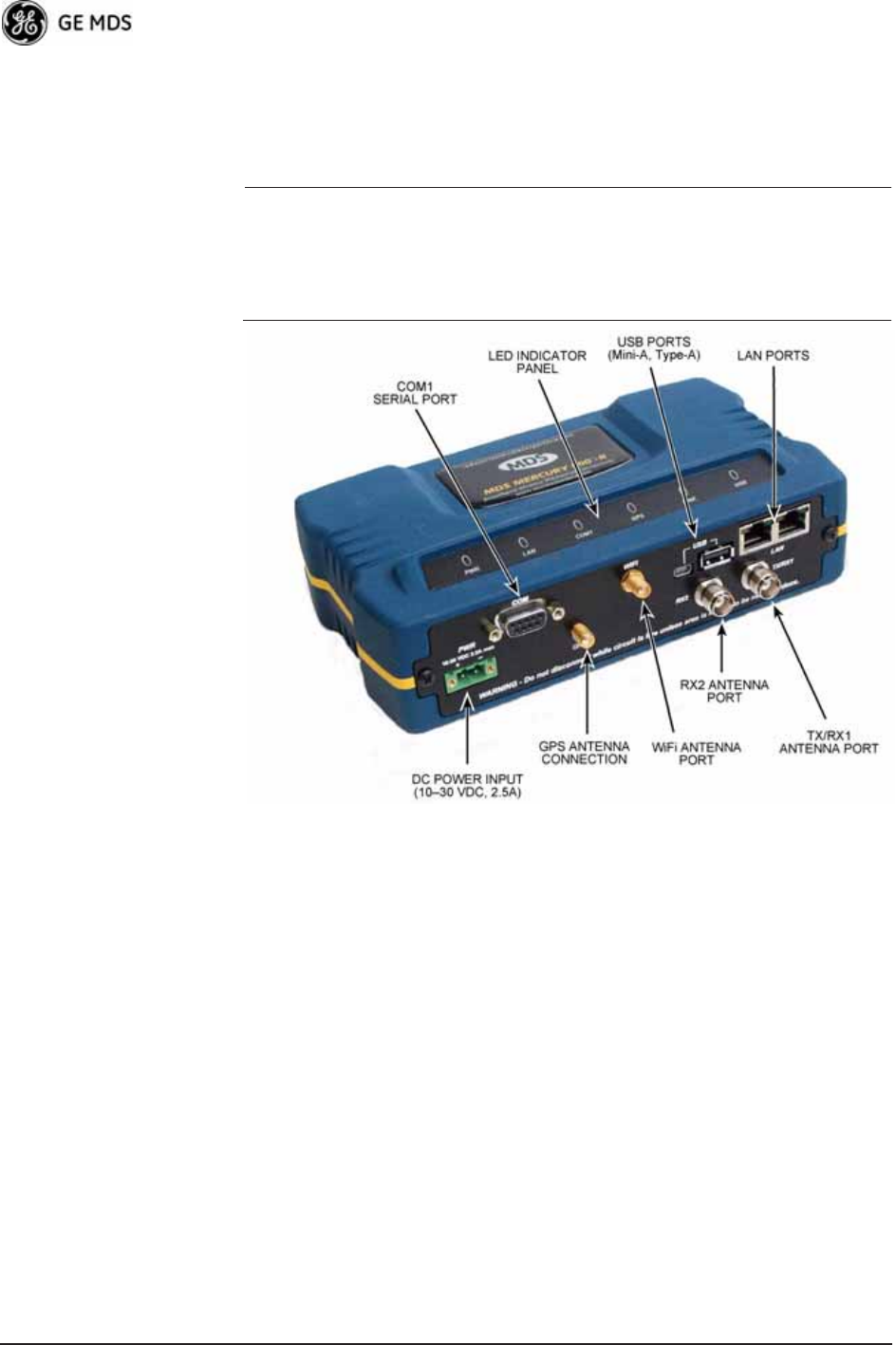
2.6.1 Option 1 Set (MaxRM) Connectors
Figure 2-4 shows the interface connectors on the front panel of the
Option 1 Set (MaxRM) Remote transceiver.
NOTE: The use of shielded Ethernet cable is recommended for
connection to the radio’s ETH port. The radio meets regulatory
emission standards without shielded cable, but shielding
reduces the possibility of interference in sensitive environ-
ments, and is in keeping with good engineering practice.
Invisible place holder
Figure 2-4. Option 1 Set Transceiver
Interface Connectors
•LED INDICATOR PANEL—Displays the basic operating status of
the transceiver. See section 2.7 on Page 29 for detailed informa-
tion.
•COM1 SERIAL PORT— DB-9 connector used for management
of the transceiver with a connected PC. INTRODUCTION on
Page 33 provides complete connection details.
•LAN PORTS—Connection point for Ethernet Local Area Net-
work. The connectors have integrated LEDs to indicate signal
activity as follows: A steady green LED indicates that a link has
been achieved; a flashing green LED indicates data activity; and
a yellow LED indicates 100 Mbps operation.
•PWR— DC power connection for the transceiver. Power source
must be 10 Vdc to 30 Vdc, negative ground, and capable of pro-
viding at least 25 watts.
05-4446A01, Rev. D Mercury Reference Manual 29
•GPS ANTENNA PORT— Coaxial connector (SMA-type) for
connection of a GPS receiving antenna. Provides 3.5 Vdc output
for compatibility with powered (active) GPS antennas. Do not
short this connector, as you might cause damage to the internal
power supply. The GPS receiving antenna’s gain must be
16 dBi or less.
NOTE: GPS functionality is required on all Access Points and
Remotes except when “Free Run” single-channel (non-frequency
hopping) operation is used, which might be possible in some
low-interference environments.
•WiFi ANTENNA PORT— Coaxial connector (SMA-type) for
attachment of a WiFi antenna. WiFI is typically used for short
range wireless communication at the transceiver site or within a
small area around the site.
•RX2 ANTENNA PORT— Coaxial connector (TNC-type) for
attachment of a second receiving antenna used in space diver-
sity arrangements.
•TX/RX1 ANTENNA PORT— Coaxial connector (TNC-type) for
attachment of the main station antenna (transmit and receive).
2.7 STEP 6—CHECK FOR NORMAL
OPERATION
Once the data equipment is connected, you can check the transceiver for
normal operation.
Observe the LEDs on the top cover for the proper indications. In a nor-
mally operating system, you will see the following LED indications
within 45 seconds of start-up:
•PWR—Lit continuously
•LINK—On, or blinking intermittently to indicate traffic flow
•LAN—On, or blinking intermittently to indicate traffic flow
Figure 2-5 shows a close-up view of the transceiver’s LED Indicator
panel. Table 2-2 provides details on each LED function.
Invisible place holder
Figure 2-5. LED Indicator Panel

30 Mercury Reference Manual 05-4446A01, Rev. D
If the radio network seems to be operating properly based on observa-
tion of the unit’s LEDs, use the PING command to verify the link integ-
rity with the Access Point.
* The LAN connector has two integrated LEDs to indicate signal activity
as follows: A steady green LED indicates that a link has been achieved;
a flashing green LED indicates data activity, and a yellow LED indicates
100 Mbps operation.
Table 2-2. Transceiver LED Functions
LED Label Activity Indication
PWR ON Primary power (DC) present
Blinking Unit in “Alarmed” state
OFF Primary power (DC) absent
LAN* ON LAN detected
Blinking Data TX/RX
OFF LAN not detected, or excessive
traffic present
COM1
(MGT System)
Blinking Data TX/RX
OFF No data activity
GPS ON Internal GPS receiver is
synchronized with the satellite
network.
Blinking AP modem is synchronizing
with the GPS timing.
OFF Internal GPS receiver is not
synchronized with the satellite
network.
LINK
(Access Point)
ON Unit is operational
OFF Not transmitting. Usually
occurs while waiting for GPS
sync.
LINK
(Remote)
ON Associated to AP
OFF Not associated with AP
USB ON USB activity on either port
OFF No USB activity

05-4446A01, Rev. D Mercury Reference Manual 31
3DEVICE MANAGEMENT
3 Chapter Counter Reset Paragraph
Contents
3.1 MS INTRODUCTION............................................................. 33
3.1.1 Differences in the User Interfaces .......................................... 33
3.2 ACCESSING THE MENU SYSTEM ...................................... 35
3.2.1 Methods of Control ................................................................. 36
3.2.2 PC Connection and Log In Procedures ................................. 36
3.2.3 Navigating the Menus ............................................................ 40
3.3 BASIC OVERVIEW OF OPERATION.................................... 42
3.3.1 Starting Information Screen ................................................... 42
3.3.2 Main Menu ............................................................................. 43
3.4 CONFIGURING NETWORK PARAMETERS ........................ 45
3.4.1 Network Configuration Menu ................................................. 45
3.4.2 Ethernet Port Configuration Menu ......................................... 55
3.4.3 Bridge Configuration .............................................................. 56
3.4.4 SNMP Agent Configuration .................................................... 57
3.4.5 AP Location Push Config Menu ............................................. 59
3.4.6 SNTP Server Configuration .................................................... 62
3.5 RADIO CONFIGURATION .................................................... 63
3.5.1 Radio Configuration Menu ...................................................... 63
3.5.2 Serial Port Configuration ........................................................ 74
3.6 MODBUS / TCP SERVER CONFIGURATION ...................... 87
3.6.1 Modbus/TCP in Mercury TransceiversAn Overview ........... 87
3.6.2 Menu Selections ..................................................................... 88
3.7 SECURITY CONFIGURATION MENU .................................. 91
3.7.1 Device Security Menu ............................................................ 92
3.7.2 Wireless Security Menu ......................................................... 94
3.7.3 IEEE 802.1x Device Authentication ....................................... 96
3.7.4 Manage Certificates ............................................................... 98
3.8 REDUNDANCY CONFIGURATION (AP ONLY).................... 101
3.9 GPS CONFIGURATION (REMOTE ONLY)........................... 106

32 Mercury Reference Manual 05-4446A01, Rev. D
3.10 DEVICE INFORMATION MENU.......................................... 108
3.11 PERFORMANCE INFORMATION MENU ........................... 109
3.12 MAINTENANCE/TOOLS MENU.......................................... 122
3.12.1 Installing Firmware via TFTP .............................................. 128
3.12.2 Auto Firmware Upgrade Menu (AP Only) ............................ 137
3.13 PERFORMANCE OPTIMIZATION ...................................... 139
3.13.1 Proper OperationWhat to Look For .................................. 142

05-4446A01, Rev. D Mercury Reference Manual 33
3.1 INTRODUCTION
The transceiver’s embedded management system is accessible through
the COM1 (serial) port, the LAN (Ethernet) port, and using over-the-air
Ethernet. Telnet, SSH, HTTP/HTTPS, and SNMP are the
Ethernet-based interfaces. Essentially, the same capabilities are avail-
able through any of these paths.
For support of SNMP software, a set of MIB files is available for down-
load from the GE MDS Web site at www.GEmds.com. An overview of
SNMP commands can be found at SNMP Agent Configuration section
on Page 57 of this manual.
The transceiver’s Management System and its functions are divided into
seven functional groups as listed below.
•Section 3.3, BASIC OVERVIEW OF OPERATION (beginning
on Page 42)
•Section 3.4, CONFIGURING NETWORK PARAMETERS
(beginning on Page 45)
•Section 3.5, RADIO CONFIGURATION (beginning on Page
63)
•Section 3.7, SECURITY CONFIGURATION MENU (beginning
on Page 91)
•Section 3.13, PERFORMANCE OPTIMIZATION (beginning on
Page 139)
•Section 3.12, MAINTENANCE/TOOLS MENU (beginning on
Page 122)
Each of these sections has a focus that is reflected in its heading. The
section you are now reading provides information on connecting to the
Management System, how to navigate through it, how it is structured,
and how to perform top-level configuration tasks. Figure 3-1 on Page 34
shows a top-level view of the Management System (MS).
3.1.1 Differences in the User Interfaces
Although there are slight differences in navigation among the user inter-
faces, the content is very similar. You will notice a few differences in
capabilities as the communications tool is driven by limitations of the
access channel. Figure 3-2 and Figure 3-3 on Page 35 show examples of
the Starting Information Screen as seen through a console terminal and
a web-browser, respectively.
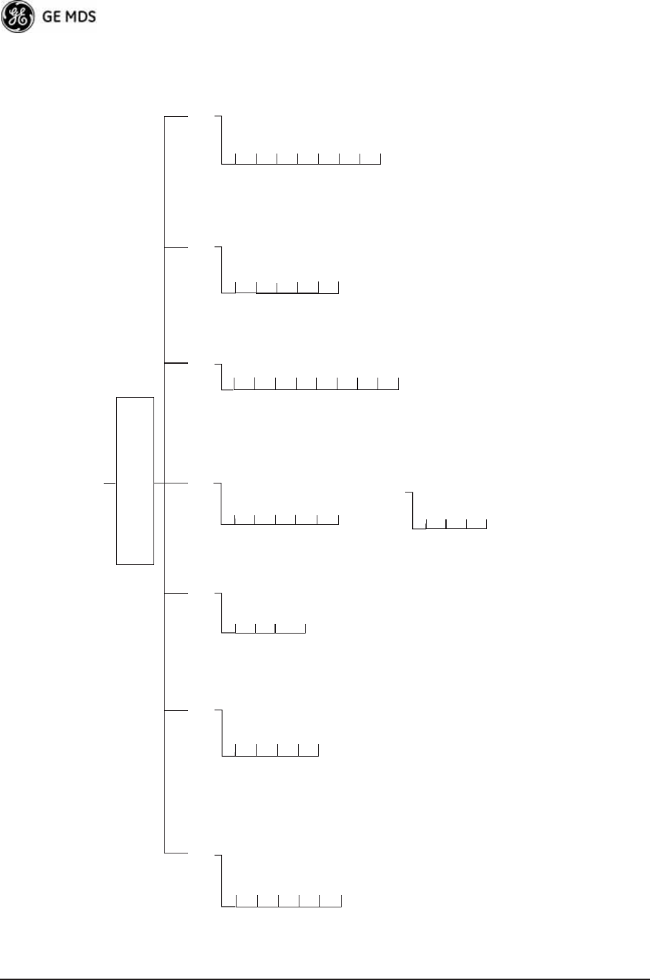
34 Mercury Reference Manual 05-4446A01, Rev. D
• Spacebar is used to make some menu selections
• AP = Access Point Only
• RM = Remote Only
Ntwk. Intfc. Config
Ethernet Port Config
Bridge Configuration
SNMP Agent Config. (AP)
AP Location Info (RM)
SNTP Server Config.
Network
Configuration Radio
Configuration Device
Information Maintenance/Tools
Security
Configuration
Reprogramming
Config. Scripts
Ping Utility
Auth. Codes
Reset to Defaults
Radio Test
F/W Versions
F/W Upgrade
MAIN MENU
Network Name
Transmit Power
Receive Pwr. (AP)
Freq. Control
Adv. Config.
Performance
Information
NOTES
• Chart shows top-level view only. See Reference Manual for details.
• Not all menu items are-user configurable
Serial Number
Uptime
Date
Date Format
Time
Model
Device Names
Console Bd. Rt.
UTC Time Offset
Device Security
Wireless Security
Event Log
Packet Statistics
GPS Status
Wireless Ntwk Stat.
Intl. Radio Stat. (RM)
Performance Trend
Manage Certif.
RADIUS
Configuration
Starting Information Screen
(Read-Only Status)
Redundancy
Configuration (AP)
Redundancy Config.
Ntwk Event Triggers
Radio Event Triggers
Hdwr Event Triggers
Red. Config. Options
Force Switchover
GPS
Configuration (RM)
Stream GPS to Console
Send GPS via UDP
GPS UDP Server IP Address
GPS UDP Server UDP Port
Figure 3-1. Embedded Management SystemTop-Level Flowchart
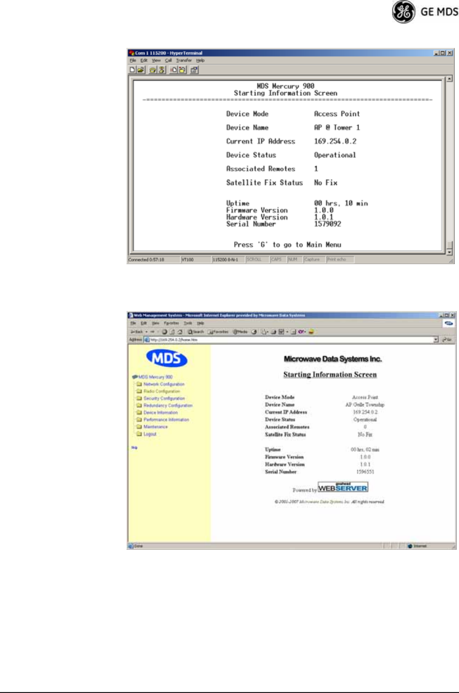
05-4446A01, Rev. D Mercury Reference Manual 35
Figure 3-2. View of MS with a text-based program
(Console Terminal shownTelnet has similar appearance)
Invisible place holder
Figure 3-3. View of the MS with a Browser
(Selections at left provide links to the various menus)
3.2 ACCESSING THE MENU SYSTEM
The radio has no external controls or adjustments. All configuration,
diagnostics, and control is performed electronically using a connected
PC. This section explains how to connect a PC, log into the unit, and
gain access to the built-in menus.

36 Mercury Reference Manual 05-4446A01, Rev. D
3.2.1 Methods of Control
Access the unit’s configuration menus in one of several ways:
•Local Console—This is the primary method used for the exam-
ples in this manual. Connect a PC directly to the COM1 port
using a serial communications cable and launch a terminal com-
munications program such as HyperTerminal (found on most
PCs by selecting Start>>Programs>>Accessories>>Communica-
tions>>HyperTerminal). This method provides text-based access to
the unit’s menu screens. Console control is a hardware-based
technique, and is intended for local use only (maximum recom-
mended cable length of 50 ft./15 m).
•Telnet or SSH*—Connect a PC to the unit’s LAN port, either
directly or via a network, and launch a Telnet session. This
method provides text-based access to the unit’s menu screens in
a manner similar to a Local Console session. You can run Telnet
sessions locally or remotely through an IP connection.
•Web Browser*—Connect a PC to the unit’s LAN port, either
directly or via a network, and launch a web browser session (for
example, Internet Explorer, Firefox, etc.). Enter the IP address
of the device to be managed into the browser’s address field.
This method provides a graphical representation of each screen,
just as you would see when viewing an Internet web site. The
appearance of menu screens differs slightly from other methods
of control, but the content and organization of screen items is
similar. Web browser sessions may be run locally or remotely
using an IP connection.
* When connecting directly to a radio, a crossover cable is required. When
connecting using a network, switch, or router, a straight-through cable is required.
3.2.2 PC Connection and Log In Procedures
The following steps describe how to access the radio’s menu system.
These steps require a PC to be connected to the unit’s COM1 or LAN port
as shown in Figure 3-4 on Page 37.
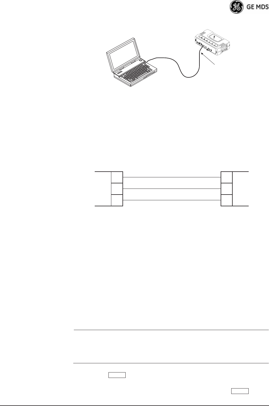
05-4446A01, Rev. D Mercury Reference Manual 37
Invisible place holder
Figure 3-4. PC Configuration Setup
Starting a Local
Console Session
(Recommended for
first-time log-in)
1. Connect a serial communications cable between the PC and the
unit’s COM1 port. If necessary, a cable may be constructed for this
purpose as shown in Figure 3-5.Invisible place holder
Figure 3-5. Serial Communications Cable (DB-9M to DB-9F)
(Maximum Recommended Cable Length 50 feet/15 meters)
2. Launch a terminal emulation program such as HyperTerminal and
configure the program with the following settings:
• 115,200 bps data rate
• 8 data bits, no parity
• One stop bit, and no flow-control
• Use ANSI or VT100 emulation.
TIP: The HyperTerminal communications program can be accessed on
most PCs by selecting this menu sequence: Start>>Programs>>Accesso-
ries>>Communications>>HyperTerminal.
NOTE: If the unit is powered-up or rebooted while connected to a
terminal, you will see a series of pages of text information
relating to the booting of the unit’s processor. Wait for the
log-in screen before proceeding.
3. Press the key to receive the login: prompt.
4. Enter the username (default username is admin). Press .
PC Running Terminal Session
(115,200 bps, 8N1)
To COM1 or LAN Port
(see text)
Transceiver
PC Running Terminal Session
(115,200 bps, 8N1)
Transceiver
To COM1 or LAN Port
(See Text)
3
5
2
3
5
2
TXD
GND
RXD
TXD
GND
RXD
DCE
DB-9 MALE
(TO MDS PRODUCT)
DTE
DB-9 FEMALE
(TO COMPUTER)
ENTER
ENTER
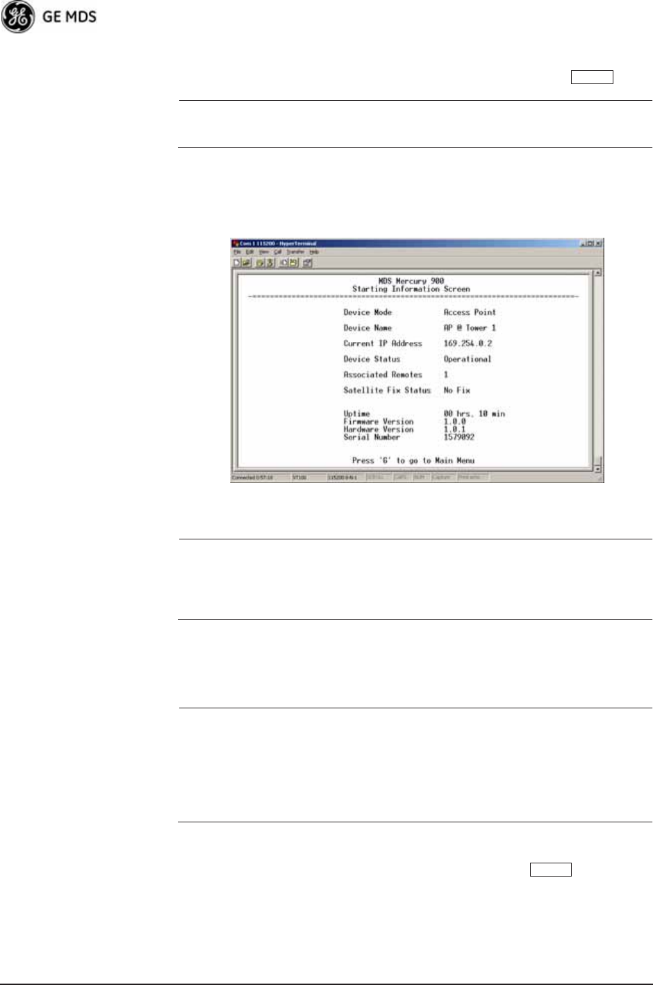
38 Mercury Reference Manual 05-4446A01, Rev. D
5. Enter your password (default password is admin). For security, your
password keystrokes do not appear on the screen. Press .
NOTE: Passwords are case sensitive. Do not use punctuation mark
characters. You may use up to 13 alpha-numeric characters.
The unit responds with the Starting Information Screen (Figure 3-6).
From here, you can review basic information about the unit or press G
to proceed to the Main Menu.
Invisible place holder
Figure 3-6. Starting Information ScreenLocal Console Session
Starting a Telnet
Session NOTE: This method requires that you know the IP address of the unit
beforehand. If you do not know the address, use the Local
Console method (above) and access the Starting Information
Screen. The address is displayed on this screen.
1. Connect a PC to the unit’s LAN port, either directly with a crossover
cable or via a network with a straight-through cable. The LAN LED
lights to indicate an active connection.
NOTE: When using Ethernet to access the unit, you might need to
change your computer’s IP address to be on the same subnet as
the radio. You can identify or verify the unit’s IP address by
using a Local Console session to communicate with the radio
through its COM1 Port and viewing the Starting Information
Screen.
2. Start the Telnet program on your computer, targeting the IP address
of the unit to which you are connected, and press .
ENTER
ENTER

05-4446A01, Rev. D Mercury Reference Manual 39
TIP: You can start a Telnet session on most PCs by selecting: Start>>Pro-
grams>>Accessories>>Command Prompt. At the command prompt
window, type the word telnet, followed by the unit’s IP address
(e.g., telnet 10.1.1.168). Press to receive the Telnet log in
screen.
NOTE: Never connect multiple units to a network with the same IP
address. Address conflicts will result in improper operation.
3. Enter your username (default username is admin). Press .
Next, the Password: prompt appears. Enter your password (default
password is admin). For security, your password keystrokes will not
appear on the screen. Press .
The unit responds with a Starting Information Screen (see
Figure 3-6 on Page 38). From here, you can review basic informa-
tion about the unit or press G to proceed to the Main Menu.
NOTE: Passwords are case sensitive. Do not use punctuation mark
characters. You may use up to 13 alpha-numeric characters.
Starting a Web
Browser Session NOTE: Web access requires that you know the IP address of the unit
you are connecting to. If you do not know the address, start a
Local Console session (see Starting a Local Console Session
(Recommended for first-time log-in) on Page 37) and access
the Starting Information Screen. The IP address is displayed
on this screen.
1. Connect a PC to the unit’s LAN port, either directly or using a
network. If connecting directly, use an Ethernet crossover cable; if
connecting using a network, use a straight-through cable. The LAN
LED lights to indicate an active connection.
2. Launch a Web-browser session on your computer (i.e., Internet
Explorer, Firefox, etc.).
3. Type the unit’s IP address and press .
4. A log-in screen is displayed (Figure 3-7 on Page 40) where you
enter a user name and password to access the unit’s menu system.
Note that the default entries are made in lower case. (Default User
Name: admin; Default Password: admin)
ENTER
ENTER
ENTER
ENTER
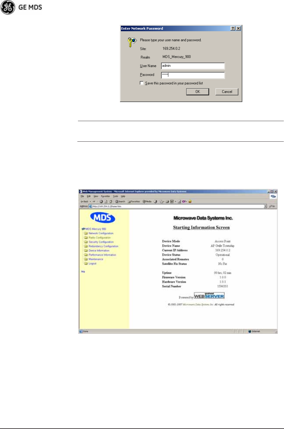
40 Mercury Reference Manual 05-4446A01, Rev. D
Invisible place holder
Figure 3-7. Log-in Screen when using a Web Browser
NOTE: Passwords are case sensitive. Do not use punctuation mark
characters. You may use up to 13 alpha-numeric characters.
5. Click OK. The unit responds with a startup menu screen similar to
that shown in Figure 3-8. From here, you can review basic informa-
tion about the unit or click one of the menu items at the left side of
the screen. Invisible place holder
Figure 3-8. Starting Information ScreenWeb Browser Example
3.2.3 Navigating the Menus
Via Terminal Telnet or SSH Sessions
Recommended for first-time log-in
Local Console, Telnet, and SSH sessions use multi-layered text menu
systems that are nearly identical. To move further down a menu tree,
you type the letter assigned to an item of interest. This takes you to an

05-4446A01, Rev. D Mercury Reference Manual 41
associated screen where settings may be viewed or changed. In most
cases, pressing the key moves the screen back one level in the
menu tree.
In general, the top portion of menu screens show read-only information
(with no user selection letter). The bottom portion of the screen contains
parameters you can select for further information, alteration of values,
or to navigate to other submenus.
NOTE: Early versions of PuTTY might not operate when using SSH
to connect to the transceiver. The latest version (0.60 at the
time of publication) does work with the transceiver’s internal
server. Both the latest released and the latest development
snapshot can be downloaded from:
www.chiark.greenend.org.uk/~sgtatham/putty/.
When you arrive at a screen with user-controllable parameter fields, you
select the menu item by pressing an associated letter on the keyboard. If
there is a user definable value, the field will clear to the right of the menu
item and you can type the value you wish to use. Follow this action by
pressing the key to save the changes. If you make a mistake or
change your mind before pressing the key, simply press
to restore the previous value.
In some cases, when you type a letter to select a parameter, you will see
a prompt at the bottom of the screen that says Choose an Option. In these
screens, press the keyboard’s to step through the available
selections. When the desired option appears, press the key to
choose that selection. In some cases, you can change several parameters
and then save them with a single keystroke. Use the key to
cancel the action and restore the previous values.
Logging Out Via
Terminal Emulator
or Telnet
From the Main Menu screen, press Q to quit and terminate the session.
NOTE: To maintain security, it is best to log-out of the menu system
entirely when you are done working with it. If you do not log
out, the session automatically ends after 10 minutes of inac-
tivity.
Navigating via Web Browser
Navigating with a Web browser is straightforward with a framed “home
page.” The primary navigation menu is permanently located on the
left-hand side of this page. Simply click the desired menu item to make
it active.
Logging Out Via
Web Browser Click Logout in the left-hand frame of the browser window. The
right-hand frame changes to a logout page. Follow the remaining
instructions on this screen.
ESCAPE
ENTER
ENTER ESCAPE
SPACEBAR
ENTER
ESCAPE
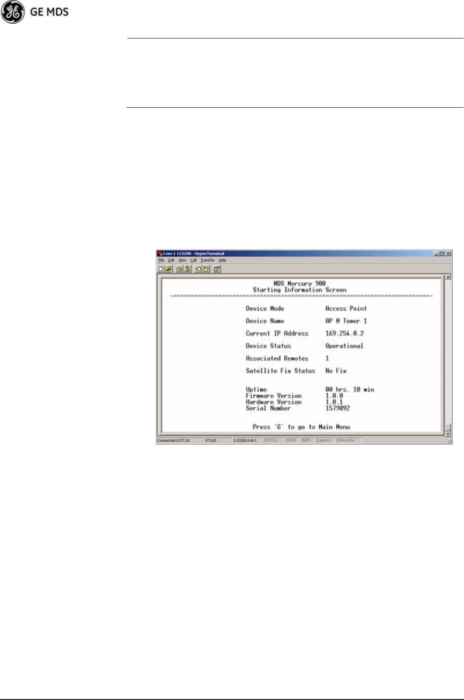
42 Mercury Reference Manual 05-4446A01, Rev. D
NOTE: In the menu descriptions that follow, parameter options/range,
and any default values are displayed at the end of the text
between square brackets. Note that the default setting is
always shown after a semicolon:
[available settings or range; default setting]
3.3 BASIC OVERVIEW OF OPERATION
3.3.1 Starting Information Screen
Once you have logged into the Management System, the Starting Infor-
mation Screen (Figure 3-9) appears with an overview of the transceiver
and its current operating conditions.
Figure 3-9. Starting Information Screen
(AP screen shown; Remote similar, differences noted below)
•Device Mode—Operating mode of the unit as it relates to the
radio network.
•Device Name—This is a user-defined parameter that appears in
the heading of all pages. (To change it, see Network Configura-
tion Menu on Page 45.)
•Current IP Address—Unit’s IP address [169.254.0.2]
•Device Status—Condition of the unit’s operation as follows:
At Access Point:
•Operational—Unit operating normally.
•Initializing—This is the first phase after boot-up.
•Synchronizing—Unit is waiting for the GPS receiver to obtain
a satellite fix and for its internal clock to synchronize to the
GPS timing signals.

05-4446A01, Rev. D Mercury Reference Manual 43
•Alarmed—The unit has detected one or more alarms that have
not been cleared.
At Remote:
•Scanning—The unit is looking for an Access Point beacon
signal.
•Ranging—Unit is adjusting power, timing, and frequency
with an AP.
•Connecting—The unit has found a valid beacon signal for its
network.
•Authenticating—Device is attempting device authentication.
•Associated —The unit has successfully synchronized and
associated with an Access Point.
•Alarmed—The unit is has detected one or more alarms that
have not been cleared.
NOTE: If an alarm is present when this screen is displayed, an “A)”
appears to the left of the Device Status field. Pressing the “A”
key on your keyboard takes you directly to the “Current
Alarms” screen.
•Associated Remotes (AP Only)—Indicates the number of
Remotes that have achieved association with the AP.
•Connection Status (Remote Only)—Indicates whether the
Remote has an RF connection with an AP.
•Satellite Fix Status—Indicates whether internal GPS receiver has
achieved synchronization with GPS satellite signals.
•Uptime—Elapsed time since the transceiver was last booted up.
•Firmware Version—Version of firmware that is currently active in
the unit.
•Hardware Version— Hardware version of the transceiver’s printed
circuit board.
•Serial Number—Make a record of this number. Provide this num-
ber when purchasing Authorization Codes to upgrade unit capa-
bilities in the future. (See “Authorization Codes” on Page 135.)
3.3.2 Main Menu
The Main Menu (Figure 3-10/Figure 3-11) is the entry point for all
user-controllable features. The transceiver’s Device Name appears at the
top of this and all other screens as a reminder of the unit you are cur-
rently controlling.
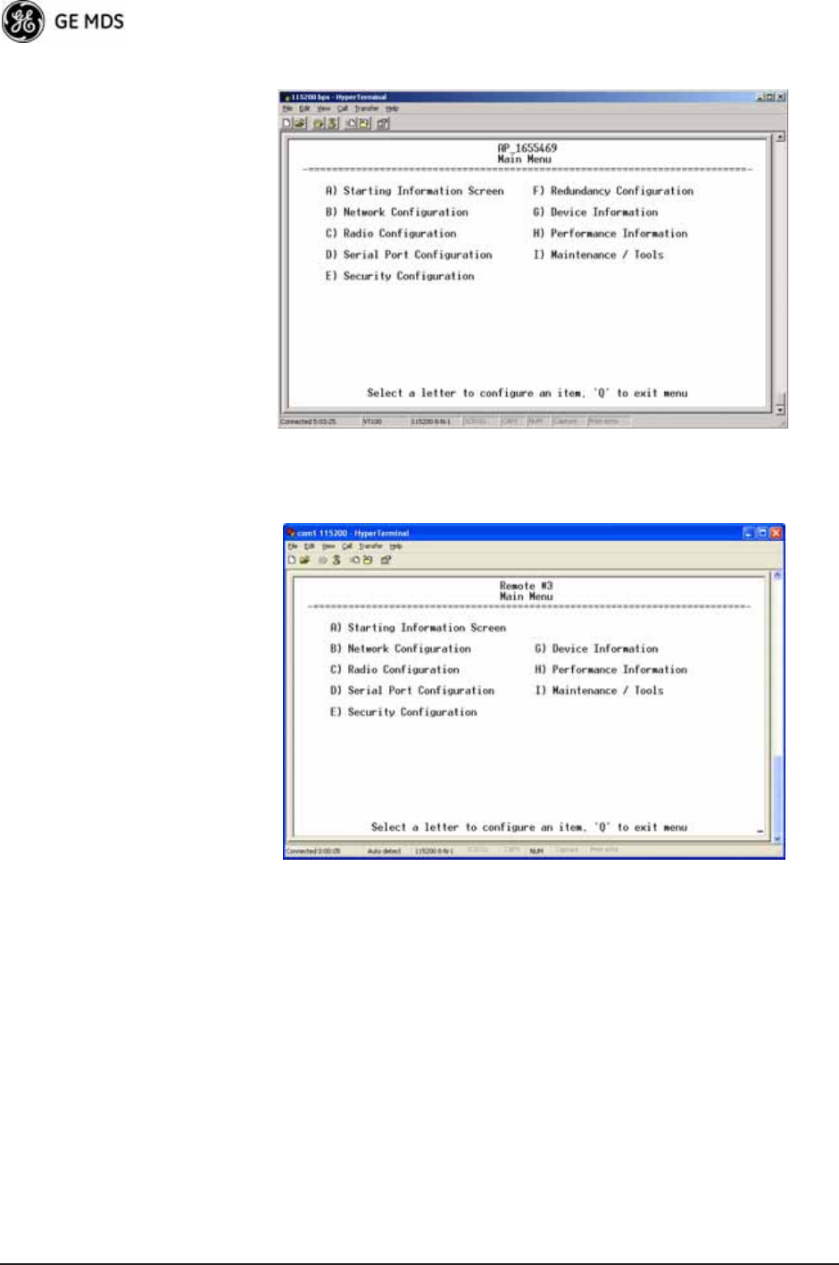
44 Mercury Reference Manual 05-4446A01, Rev. D
Figure 3-10. Main Menu (AP)
(AP menu shown, Remote similar; Differences noted in text below)
Figure 3-11. Main Menu (MDS 3650 Remote Only)
•Starting Information Screen—Select this item to return to the Start-
ing Information screen described above.
•Network Configuration—Tools for configuring the data network
layer of the transceiver. (See “CONFIGURING NETWORK
PARAMETERS” on Page 45)
•Radio Configuration—Tools to configure the wireless (radio)
layer of the transceiver. (See “RADIO CONFIGURATION” on
Page 63)
•Serial Port Configuration—Menus for tailoring the COM1 port for
data mode operation (data only). (See “Serial Port Configura-
tion” on Page 74)
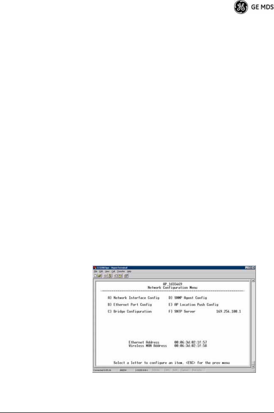
05-4446A01, Rev. D Mercury Reference Manual 45
•Security Configuration—Tools to configure the security services
available with the transceiver’s environment. (See “SECURITY
CONFIGURATION MENU” on Page 91)
•Redundancy Configuration—(AP Only) Allows setting of the cri-
teria for switchover in the event of loss of associated Remotes
or excessive packet receive errors.
•GPS Configuration—(Remote Only; not available on MDS 3650
model) View/set parameters related to GPS streaming location
output. (See “GPS CONFIGURATION (REMOTE ONLY)” on
Page 106)
•Device Information—Top level device fields such as model, serial
number, date/time, etc. (See “DEVICE INFORMATION
MENU” on Page 108)
•Performance Information—Status information relating to the radio
and data layer’s performance in the radio network.
(See “PERFORMANCE INFORMATION MENU” on
Page 109)
•Maintenance/Tools—Tools for upgrading firmware code and test-
ing major unit capabilities. (See “MAINTENANCE/TOOLS
MENU” on Page 122)
3.4 CONFIGURING NETWORK
PARAMETERS
3.4.1 Network Configuration Menu
The Network Configuration Menu is the home of several parameters that
you should review and set as necessary before placing a transceiver into
service.
Figure 3-12. Network Configuration Menu
(Standard radio)
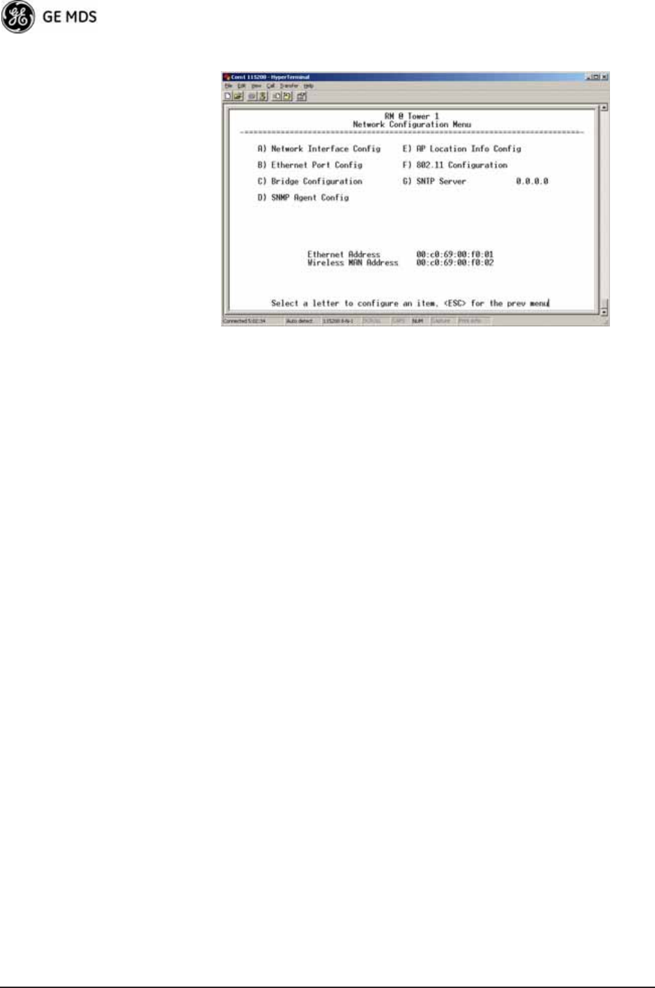
46 Mercury Reference Manual 05-4446A01, Rev. D
Figure 3-13. Network Configuration Menu
(MaxRM radio)
•Network Interface Config—Presents a menu where you can view or
set various parameters (VLAN Status, IP Configuration, and
DHCP Server Configuration).
•Ethernet Port Config—Presents a menu for defining the status of
the Ethernet port (enabled or disabled), port follows association,
and Ethernet filtering configuration. Detailed explanations of
this menu are contained in Ethernet Port Configuration Menu on
Page 55.
•Bridge Configuration—View/set options for Ethernet Bridge oper-
ation.
•SNMP Agent Config—View/set SNMP configuration parameters.
See “SNMP Agent Configuration” on Page 57 for more infor-
mation.
•AP Location Info Config—On an AP this submenu allows for con-
figuring an AP to automatically download the AP Locations
File to its associated Remotes. On a Remote this submenu
allows for downloading an AP Locations File. See “AP Loca-
tion Push Config Menu” on Page 59 for additional details.
•802.11 Configuration—Presents a submenu for configuring the
radio’s internal WiFi module to be an Access Point for other
WiFi devices (APs), to connect to a WiFi Access Point at
another location (Station), or to connect directly to another
WiFi device (Ad-Hoc).
•SNTP Server—Address of SNTP server (RFC 2030) from which
the transceiver will automatically get the time-of-day. You can
also manually set the date and time. A Mercury unit tries to get
the time and date from the SNTP server only if an IP address is
configured. It will continue to retry every minute until it suc-
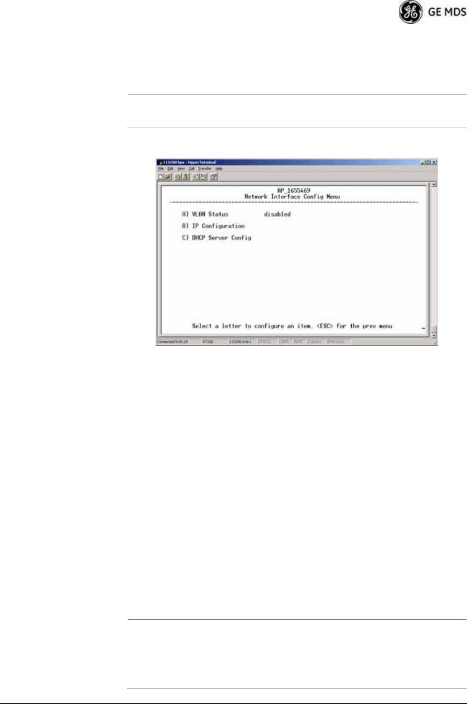
05-4446A01, Rev. D Mercury Reference Manual 47
ceeds.
The transceivers use UTC (Universal Time Coordinated) with a
configurable time offset. [0]
NOTE: The Mercury gets time of day data from the GPS receiver if the
receiver gets a satellite fix.
Network Interface Configuration Submenu
Invisible place holder
Figure 3-14. Network Interface Configuration Submenu
•VLAN Status—This selection is used to enable or disable virtual
LAN operation. For details, refer to VLAN Configuration Menu
on Page 47. [enable, disabled; disabled]
•IP Configuration—This selection presents a submenu for config-
uring the local IP address of the transceiver. Detailed explana-
tions are provided in the section titled IP Configuration Menu
on Page 53.
•DHCP Server Config—Menu for configuration of DHCP services
by the Access Point. DHCP provides “on-the-fly” IP address
assignments to other LAN devices, including Mercury Series
units. For details, refer to DHCP Server Configuration (Data
and Mgmt) on Page 50.
VLAN Configuration Menu
The VLAN Configuration menu (Figure 3-15) becomes active and vis-
ible when you enable VLAN Status on the Network Interface Configura-
tion Menu, and you press the Enter key.
CAUTION:The VLAN Status parameter must be consistent at both the
Access Point and Remote radios in order for data to flow
correctly. Failure to do so might result in data not being trans-
ported correctly even when the radios are in an associated state
and able to communicate over-the-air.
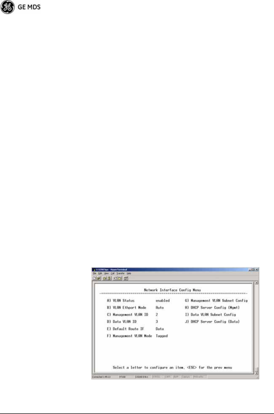
48 Mercury Reference Manual 05-4446A01, Rev. D
About Virtual LAN in
Mercury A VLAN is essentially a limited broadcast domain, meaning that all
members of a VLAN receive broadcast frames sent by members of the
same VLAN but not frames sent by members of a different VLAN. For
more information, refer to the IEEE 802.1Q standard.
The transceiver supports port-based VLAN at the Ethernet interface and
over the air, according to the IEEE 802.1Q standard. When VLAN Status
is enabled, the wireless port of both AP and Remote radios act,
according to user configuration, as either a trunk port or access port.
The Ethernet port of an Access Point radio is normally configured as a
trunk port. This type of port expects incoming frames to have a VLAN ID
tag and sends outgoing frames with a VLAN tag as well.
The Ethernet port of a Mercury radio can be configured as an access port
or as a trunk port.
When the Ethernet port of a Mercury radio is configured as VLAN
Access Port, the radio tags incoming traffic with a VLAN ID, and strips
the tag before sending traffic out. This VLAN is known as the DATA
VLAN. Additionally, a second VLAN is assigned for other traffic that
is terminated at the radio, such as SNMP, TFTP, ICMP, Telnet, and so
on. This is known as the MANAGEMENT VLAN. Traffic directed to
the integrated terminal server that handles the serial ports is assigned to
the DATA VLAN.
When the Ethernet port of a remote radio is configured as a VLAN
trunk, the radio expects all incoming Ethernet frames to be tagged, and
passes all outgoing frames as received from the wireless link, with the
unchanged VLAN tag.
Network Interface Configuration Submenu—VLAN Items
Invisible place holder
Figure 3-15. VLAN Configuration Menu

05-4446A01, Rev. D Mercury Reference Manual 49
•VLAN Status—Defines whether the radio handles Ethernet
frames in “extended” 802.1Q mode or in “normal” mode in the
Ethernet port. If configured with a trunk port, the Mercury
passes all tagged traffic regardless of the VLAN ID. The Mer-
cury only uses the Data VLAN ID parameter when the ETH port is
configured as an Access Port.
[enabled, disabled; disabled]
•VLAN Ethport Mode—Defines if the Ethernet port acts as a trunk
port or as an access port. Auto mode defines the port as a trunk
port in an AP, or an access port in a Remote radio.
[Auto, Trunk, Access; Auto]
•Management VLAN ID—Defines the VLAN ID for traffic directed
to the radio itself, other than the terminal server process. This
VLAN ID is used for filtering and for tagging purposes.
[1-4094; 2]
•Data VLAN ID—Defines the VLAN ID assigned to traffic directed
to and from the Ethernet port and the terminal server process in
the radio. This VLAN ID is used for filtering and tagging pur-
poses. [1-4094; 3]
•Default Route IF—Defines the VLAN that contains the default
gateway in the radio. [MGMT, DATA; MGMT]
•Management VLAN Mode—Applies the VLAN tag to management
frames. [Tagged, Native; Tagged].
•Management VLAN Subnet Config—Presents a screen where you
can set the IP Address Mode, Static IP Address, and Static IP
Netmask (see Figure 3-16 on Page 50).
•DHCP Server Config (Mgmt)—Presents a screen where you can
view or set the DHCP server status and address information for
management functions (see Figure 3-17 on Page 51).
•Data VLAN Subnet Config—Presents a screen where you can view
or set the IP mode and address information (see Figure 3-19 on
Page 52).
•DHCP Server Config (Data)—Presents a screen where you can view
or set DHCP server status and address information for data
functions (see Figure 3-18 on Page 52).
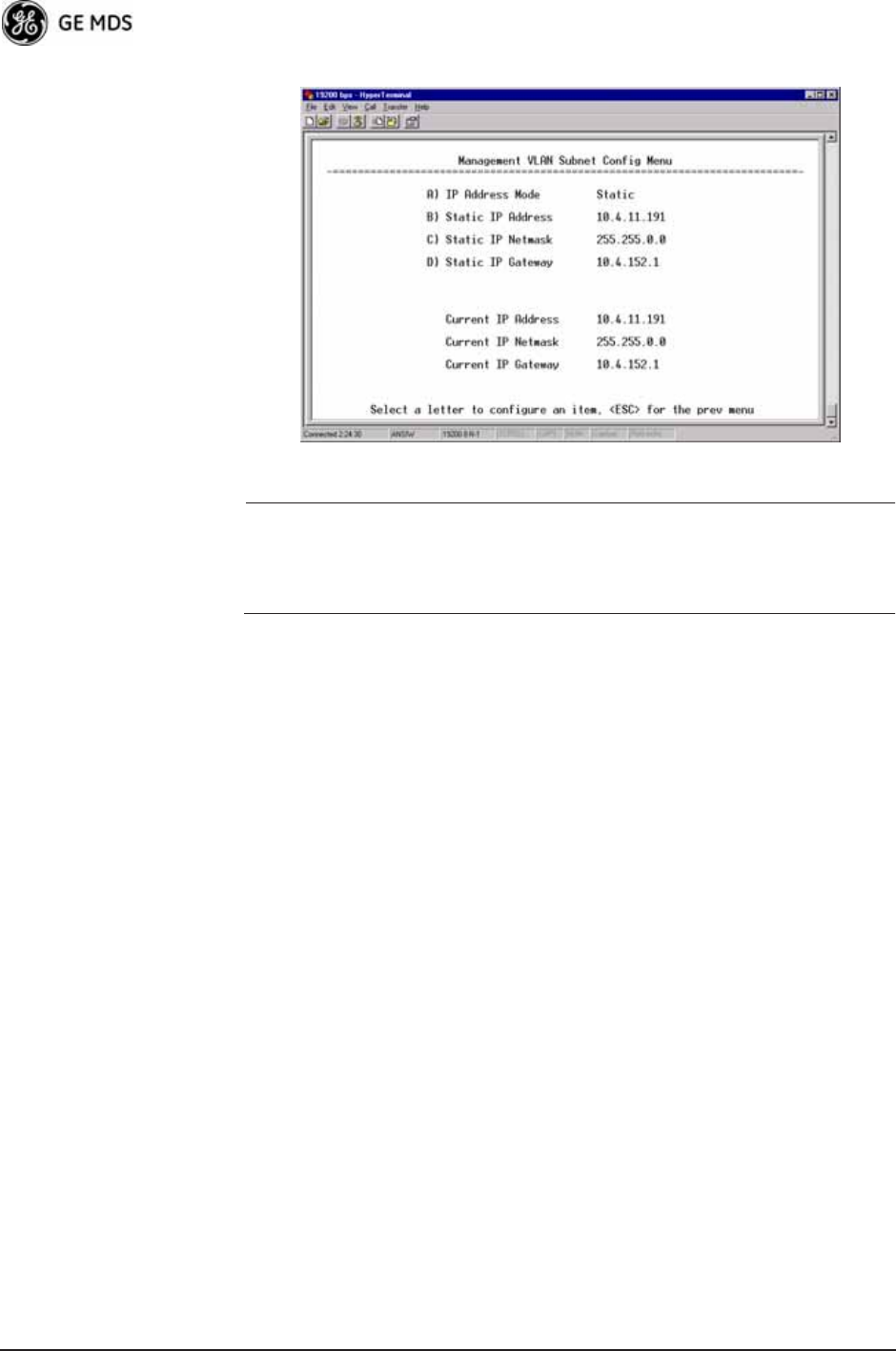
50 Mercury Reference Manual 05-4446A01, Rev. D
Management VLAN
Subnet
Configuration Menu
Invisible place holder
Figure 3-16. Management VLAN Subnet Configuration Menu
NOTE: Changes to any of the following parameters while communi-
cating over the network (LAN or over-the-air) might cause a
loss of communication with the unit you are configuring. You
must re-establish communication using the new IP address.
•IP Address Mode—Defines the source of the IP address of this
device. Only static IP addressing mode is available when VLAN
Status is enabled. [Static, Dynamic; Static]
•Static IP Address—The IPv4 local IP address. [192.168.1.1]
•Static IP Netmask—The IPv4 local subnet mask. This value is
used when the radio attempts to send a locally initiated message,
either from the terminal server, or from a management process.
[255.255.0.0]
The lower three lines of the screen (Current IP Address, Current IP Netmask,
Current IP Gateway) show the current addressing configured at the trans-
ceiver. Current IP Gateway only displays on this screen if Default Route IF
on the Network Interface Config menu (Figure 3-15 on Page 48) is set to
Management.
Selecting option I from the menu in Figure 3-15 on Page 48 displays the
screen shown in Figure 3-19 on Page 52. Note that the IP address is dif-
ferent even though it is the same physical unit. This is because this IP
address is defined for a different VLAN.
DHCP Server
Configuration
(Data and Mgmt)
A transceiver can provide automatic IP address assignments to other IP
devices in the network by providing DHCP (Dynamic Host Configura-
tion Protocol) services. This service eliminates setting an individual
device IP address on Remotes in the network, but it requires some plan-
ning of the IP address range. One drawback to network-wide automatic
IP address assignments is that SNMP services might become inacces-
sible as they are dependent on fixed IP addresses.
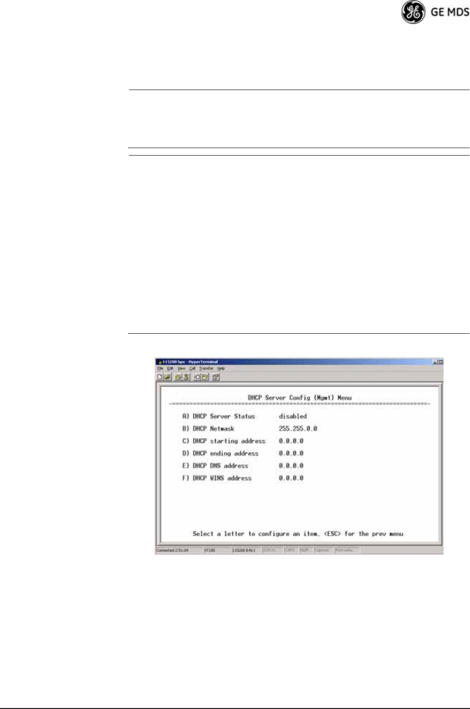
05-4446A01, Rev. D Mercury Reference Manual 51
You can make a network of radios with the DHCP-provided IP address
enabled or with DHCP services disabled. In this way, you can accom-
modate locations for which a fixed IP address is desired.
NOTE: There should be only one active DHCP server in a network. If
more than one DHCP server exists, network devices might
randomly get their IP address from different servers every time
they request one.
NOTE: Combining DHCP and IEEE 802.1x device authentication
might result in a non-working radio if the DHCP server is
located at a Remote radio site. If possible, place the DHCP
server at the AP location.
A DHCP server can be run at a Remote, but it is not recom-
mended if 802.1x Device Authentication is in use and if the AP
gets its IP address from the DHCP server on the Remote. In
this case, the Remote cannot authenticate to allow the AP to
get its address, because the AP needs an address to perform
802.1x device authentication. This results in an unsolvable
condition where the AP needs to get an IP address from DHCP
at the Remote, but it can’t get the address until it is authenti-
cated.
Invisible place holder
Figure 3-17. DHCP Server Configuration (Mgmt) Menu
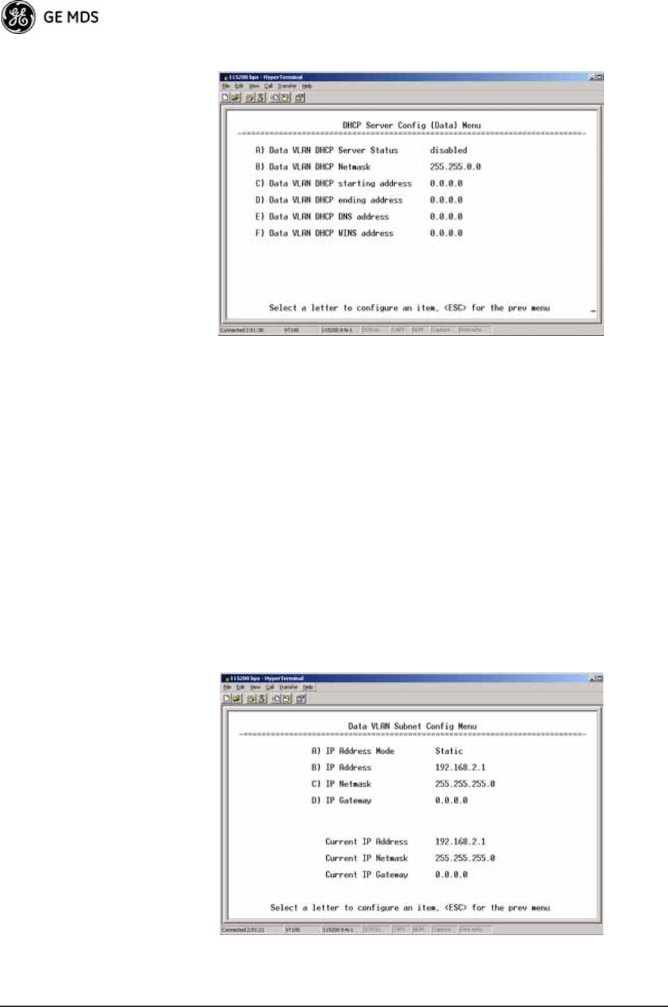
52 Mercury Reference Manual 05-4446A01, Rev. D
Invisible place holder
Figure 3-18. DHCP Server Configuration (Data) Menu
•DHCP Server Status—Enable/Disable the response to DHCP
requests to assign an IP address. [Disabled/Enabled; Disabled]
•DHCP Netmask—IP netmask to be assigned along with the IP
address in response to a DHCP request. [0.0.0.0]
•DHCP starting address—Lowest IP address in the range of
addresses provided by this device. [0.0.0.0]
•DHCP ending address—Highest IP address in the range of
addresses provided by this device. A maximum of 256
addresses is allowed in this range. [0.0.0.0]
•DHCP DNS address—Domain Name Server address provided by
this service.
•DHCP WINS address—Windows Internet Naming Service server
address provided by this service.
Data VLAN Subnet
Configuration Menu Invisible place holder
Figure 3-19. Data VLAN Subnet Configuration Menu
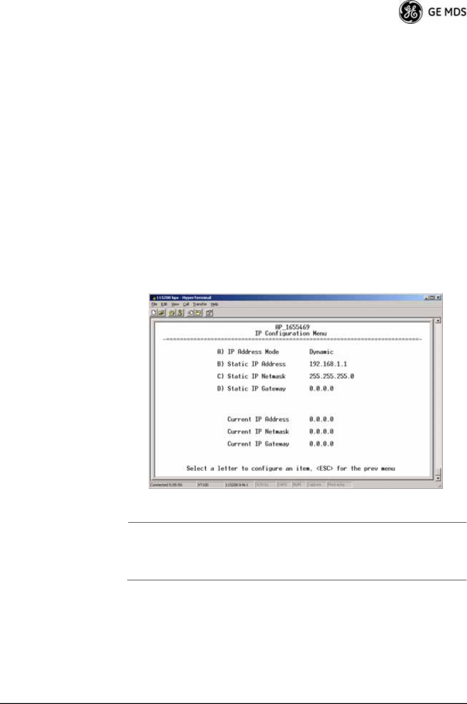
05-4446A01, Rev. D Mercury Reference Manual 53
•IP Address Mode—Defines the source of this device’s IP address.
Only static IP addressing mode is available when VLAN Status
is enabled [Static; Static]
•IP Address—The IPv4 local IP address. [192.168.1.1]
•IP Netmask—The IPv4 local subnet mask. This value is used
when the radio attempts to send a locally initiated message,
from either the terminal server or the management process.
[255.255.0.0]
•IP Gateway—The IPv4 address of the default gateway device,
typically a router. [0.0.0.0]
The lower three lines of the screen (Current IP Address, Current IP Netmask,
and Current IP Gateway) show the current addressing configured at the
transceiver. Current IP Gateway only displays on this screen if Default Route
IF on the Network Interface Config menu (Figure 3-15 on Page 48) is set to
Data.
Invisible place holder
IP Configuration Menu
Figure 3-20. IP Configuration Menu
CAUTION: Changes to the following parameters while communicating
over the network (LAN or over-the-air) might cause a loss of
communication with the unit being configured. You must
re-establish communication using the new IP address.
•IP Address Mode—Defines the source of this device’s IP address.
[Static, Dynamic; Static]
•Static IP Address (User Review Recommended)—Essential for con-
nectivity to the transceiver’s MS using the LAN port. Enter any
valid IP address that is unique within the network. This field is
unnecessary if DHCP is enabled. [192.168.1.1]
•Static IP Netmask—The IPv4 local subnet mask. This field is
unnecessary if DHCP is enabled. [255.255.0.0]
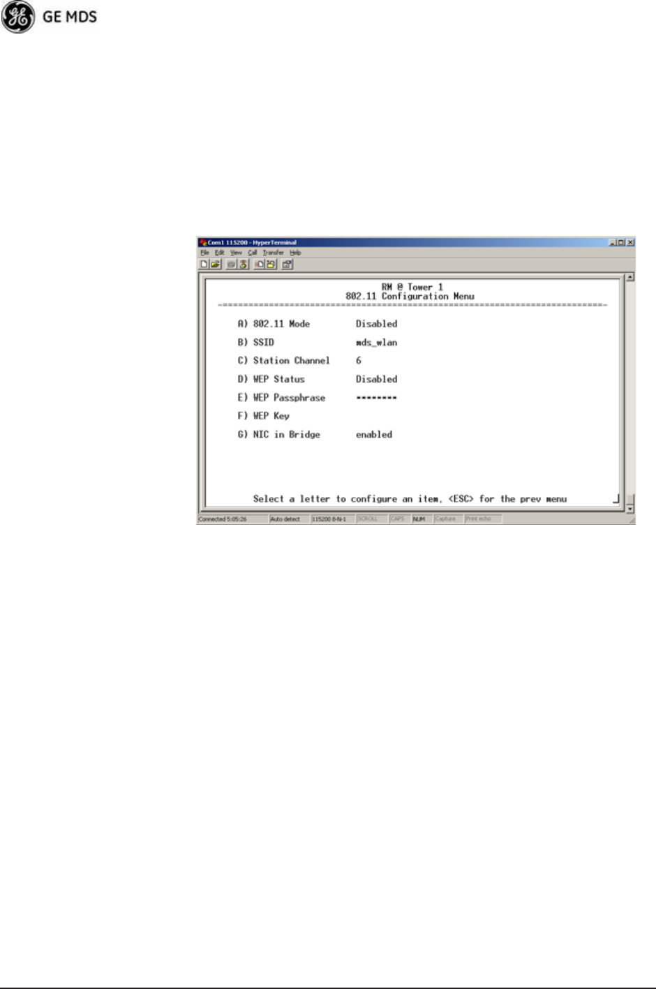
54 Mercury Reference Manual 05-4446A01, Rev. D
•Static IP Gateway—The IPv4 address of the network gateway
device, typically a router. This field is unnecessary if DHCP is
enabled. [0.0.0.0]
The lower three items on the screen (Current IP Address, Net-
mask and Gateway) show the actual addressing at the trans-
ceiver whether it was obtained from static configuration or from
a DHCP server.
802.11 Configuration Submenu Invisible place holder
Figure 3-21. 802.11 Configuration Submenu
•802.11 Mode—Configures the WiFi radio to be an Access Point
for other WiFi devices (AP), to connect to a WiFi Access Point
at another location (Station), or to connect directly to another
WiFi device (Ad-Hoc).
•SSID—Service Set Identifier, the name of the wireless LAN to
which to connect. This is equivalent to Network Name in GE
MDS terminology.
•Station Channel—Sets the 802.11 channel the device will use.
This can only be set to Auto when in Station mode.
•WEP Status—The type of WEP encryption being used, if any.
•WEP Passphrase—The Passphrase used in WEP encryption.
•WEP Key—The key used in WEP encryption. This key should be
entered in hexadecimal format preceded by 0x. The key should
be 13 or 26 hexadecimal characters. For example,
0x1a2b3c4d5e6f709a8b7c6d5e4f.
•NIC in Bridge—When enabled, the WiFi interface is added to the
network bridge, allowing traffic to pass between the WiFi and
the other interfaces (LAN and wireless).
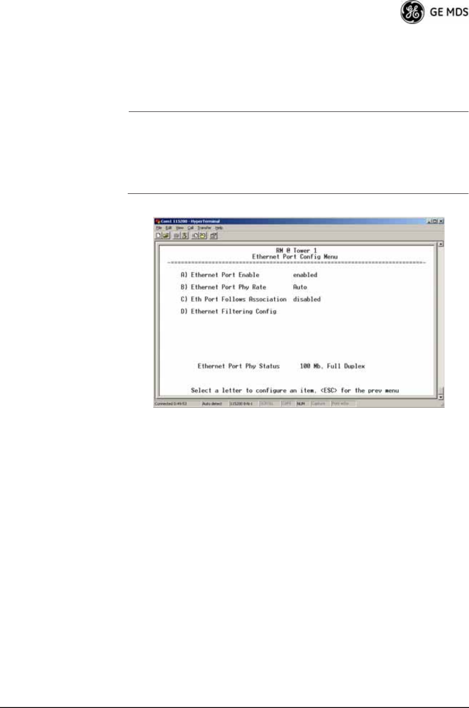
05-4446A01, Rev. D Mercury Reference Manual 55
3.4.2 Ethernet Port Configuration Menu
The transceiver allows for special control of the Ethernet interface, to
allow traffic awareness and availability of the backhaul network for
redundancy purposes.
NOTE: The transceiver’s network port supports 10BaseT and
100BaseT connections. Confirm that your hub/switch is
capable of auto-switching data rates.
To prevent excessive Ethernet traffic from degrading perfor-
mance, place the transceiver in a segment, or behind routers.
Invisible place holder
Figure 3-22. Ethernet Port Configuration Menu
(MaxRM radio)
•Ethernet Port Enable—Allows enabling/disabling Ethernet traffic
for security purposes. Setting it to enabled enables the port.
[enabled, disabled; enabled]
•Ethernet Port Phy Rate—The Ethernet port’s configured speed.
•Eth Port Follows Association (Remote Only)—When enabled, the
Ethernet port is disabled until the Remote associates. This
allows a PC or laptop connected to the Remote to know when
the wireless link is available. This feature helps middleware on
the laptop in making connectivity decisions. In addition, if the
Remote moves between Access Points on different subnets,
then the laptop can DHCP for a new address when the link
comes back up. [enabled, disabled; disabled]
•Ethernet Filtering Config—Allows enabling/disabling filtering and
specifying of Ethernet addresses.
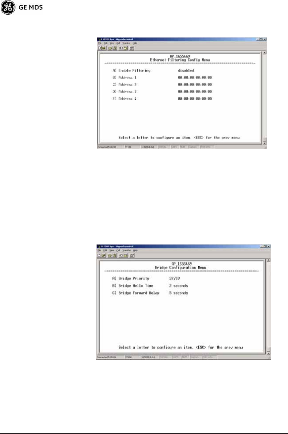
56 Mercury Reference Manual 05-4446A01, Rev. D
Ethernet Filtering Configuration Menu
Invisible place holder
Figure 3-23. Ethernet Filtering Configuration Menu
•Enable Filtering—Activates Ethernet filtering.
[enabled, disabled; disabled]
•Address 1, 2, 3, 4—Ethernet address fields. When filtering is
enabled, the Mercury only accepts traffic on its Ethernet port
from the configured addresses.
[Valid MAC address string]
3.4.3 Bridge Configuration Invisible place holder
Figure 3-24. Bridge Configuration Menu
•Bridge Priority—View/set the priority of the bridge in the span-
ning tree. [0-65535; 32769]
•Bridge Hello Time—View/set spanning tree hello time. This
parameter affects how often the bridge sends a spanning tree
Bridge Protocol Data Unit (BPDU). [1-10 seconds; 2 seconds]

05-4446A01, Rev. D Mercury Reference Manual 57
•Bridge Forward Delay—View/set spanning tree forwarding delay.
Affects how long the bridge spends listening and learning after
initialization. [4-30 seconds; 5 seconds].
3.4.4 SNMP Agent Configuration
The transceiver contains over 100 custom SNMP-manageable objects as
well as the IETF standard RFC1213 for protocol statistics, also known
as MIB II. You can use off-the-shelf SNMP managers to access the
transceiver’s SNMP Agent’s MIB, such as Castle Rock Computing
SNMPc™ and Hewlett Packard OpenView™. The transceiver’s SNMP
agent supports SNMPv1, v2, and v3.
The objects are split into nine MIB files for use with your SNMP man-
ager. There are textual conventions, common files, and specific files.
This allows the flexibility to change areas of the MIB and not affect
other existing installations or customers.
•msdreg.mib—MDS sub-tree registrations
•mds_comm.mib—MDS Common MIB definitions for objects
and events common to the entire product family
•mercury_reg.mib—MDS sub-tree registrations
•mercurytrv1.mib—SNMPv1 enterprise-specific traps
•mercurytrv2.mib—SNMPv2 enterprise-specific traps
•mercury_comm.mib— MIB definitions for objects and events
common to the entire Mercury Series
•mercury_ap.mib—MIB definitions for objects and events for an
Access Point transceiver
•mercury_rem.mib—Definitions for objects and events for a
Remote radio
•mercury_sec.mib—For security management of the radio system
NOTE: SNMP management requires that the proper IP address,
network, and gateway addresses are configured in each associ-
ated network transceiver.
In addition, some management systems might require that you
compile the MIB files in the order shown above.
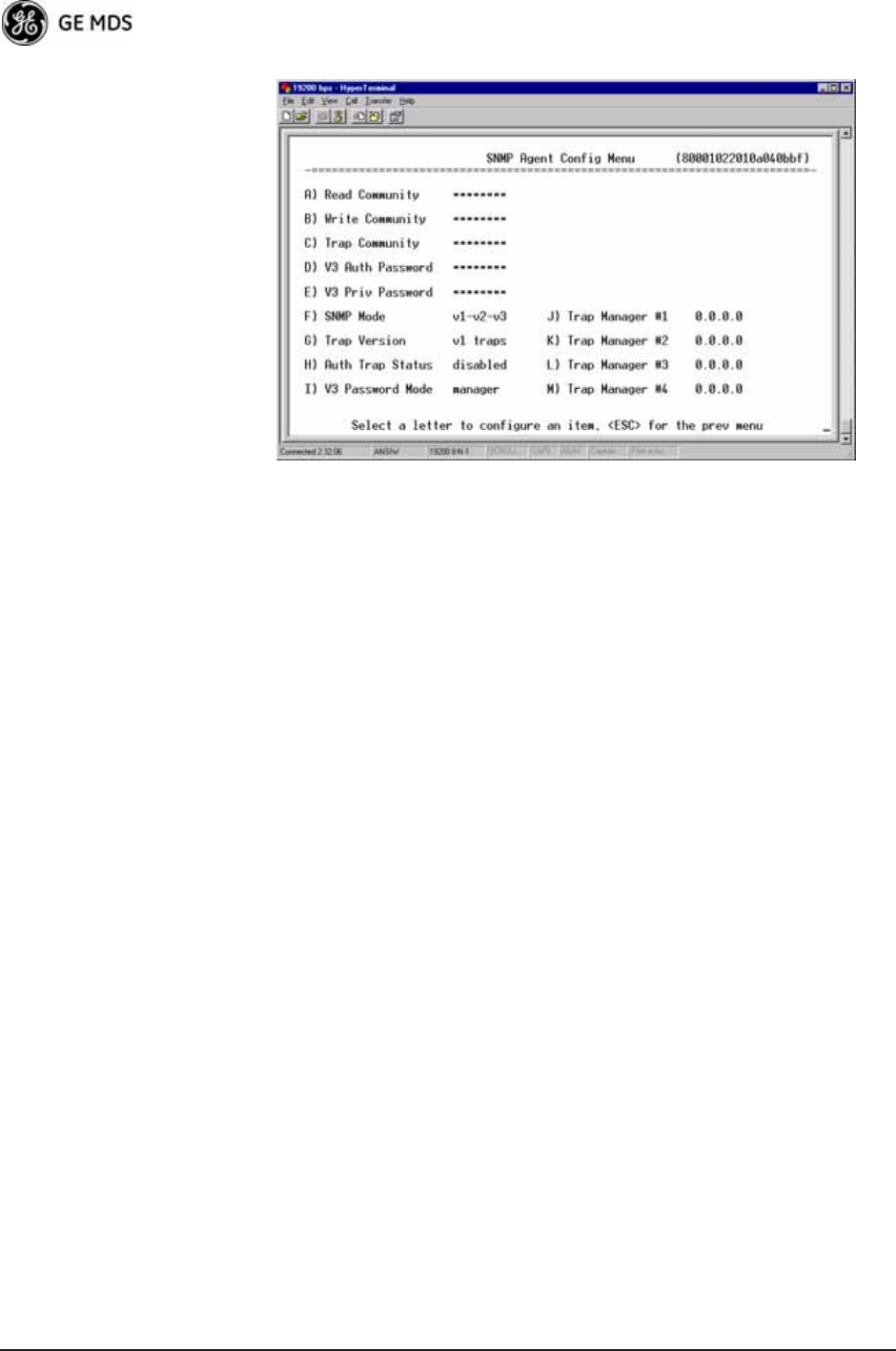
58 Mercury Reference Manual 05-4446A01, Rev. D
Invisible place holder
Figure 3-25. SNMP Server Configuration Menu
This menu provides configuration and control of vital SNMP functions.
•Read Community String—SNMP community name with
SNMPv1/SNMPv2c read access. This string can contain up to
30 alpha-numeric characters.
•Write Community String—SNMP community name with
SNMPv1/SNMPv2c write access. This string can contain up to
30 alpha-numeric characters.
•Trap Community String—SNMP community name with
SNMPv1/SNMPv2c trap access. This string can contain up to
30 alpha-numeric characters.
•V3 Authentication Password—Authentication password stored in
flash memory. This is used when the Agent is managing pass-
words locally (or initially for all cases on reboot). This is the
SNMPv3 password used for Authentication (currently, only
MD5 is supported). This string can contain up to 30
alpha-numeric characters.
•V3 Privacy Password—Privacy password stored in flash memory.
Used when the SNMP Agent is managing passwords locally (or
initially for all cases on reboot). This is the SNMPv3 password
used for privacy (DES encryption). This string can contain
between 8 and 30 alpha-numeric characters.
•SNMP Mode—This specifies the mode of operation of the radio’s
SNMP Agent. The choices are: disabled, v1_only, v2_only,
v3_only, v1-v2, and v1-v2-v3. If the mode is disabled, the Agent
does not respond to any SNMP traffic. If the mode is v1_only,
v2_only, or v3_only, the Agent responds only to that version of
SNMP traffic. If the mode is v1-v2 or v1-v2-v3, the Agent
responds to the specified version of SNMP traffic. [v1-v2-v3]
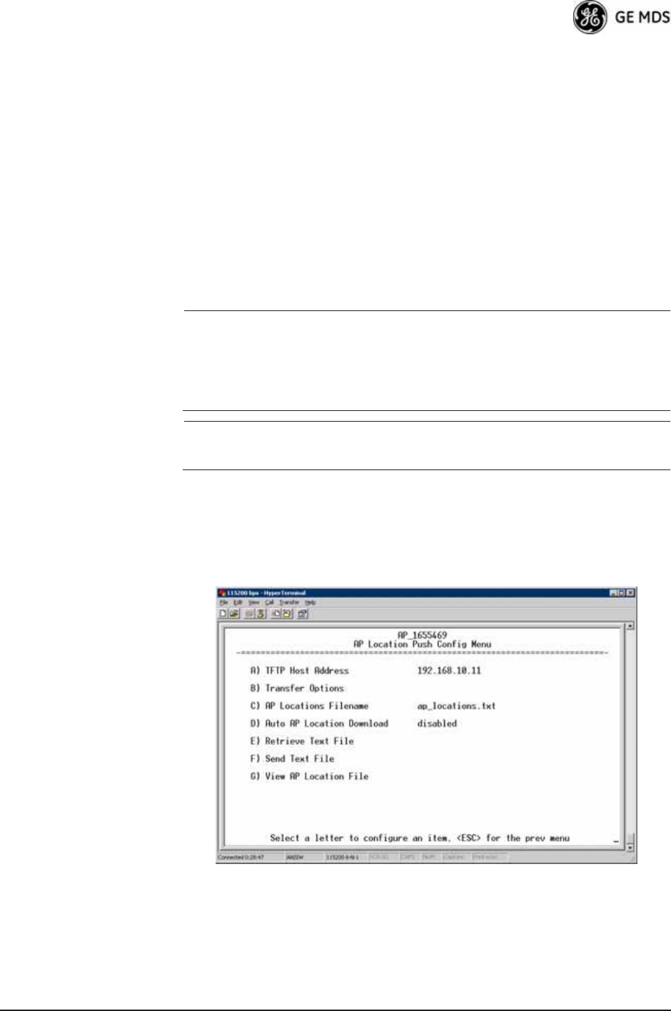
05-4446A01, Rev. D Mercury Reference Manual 59
•Trap Version—This specifies which version of SNMP is used to
encode the outgoing traps. The choices are v1_traps, v2_traps,
and v3_traps. When v3_traps is selected, v2-style traps are sent,
but with a v3 header. [v1_traps, v2_traps, v3_traps]
•Auth Traps Status—Indicates whether or not traps are generated
for failed authentication of an SNMP PDU. [Disabled/Enabled;
Disabled]
•SNMP V3 Passwords—Determines whether v3 passwords are
managed locally or via an SNMP Manager. The different behav-
iors of the Agent, depending on the mode selected, are described
in SNMP Mode above.
•Trap Manager #1—#4— Table of up to four locations on the net-
work to which traps are sent. [Any standard IP address]
NOTE: The number in the upper right-hand corner of the screen is the
SNMP Agent’s SNMPv3 Engine ID. Some SNMP Managers
may need to know this ID in order interface with the trans-
ceiver’s SNMP Agent. The ID only appears on the screen
when SNMP Mode is either v1-v2-v3 or v3_only.
NOTE: For more SNMP information, see “NOTES ON SNMP” on
Page 178.
3.4.5 AP Location Push Config Menu
This menu configures the AP for updating connected remotes with the
AP Locations File loaded on the AP.
Invisible place holder
Figure 3-26. AP Location Push Config Menu
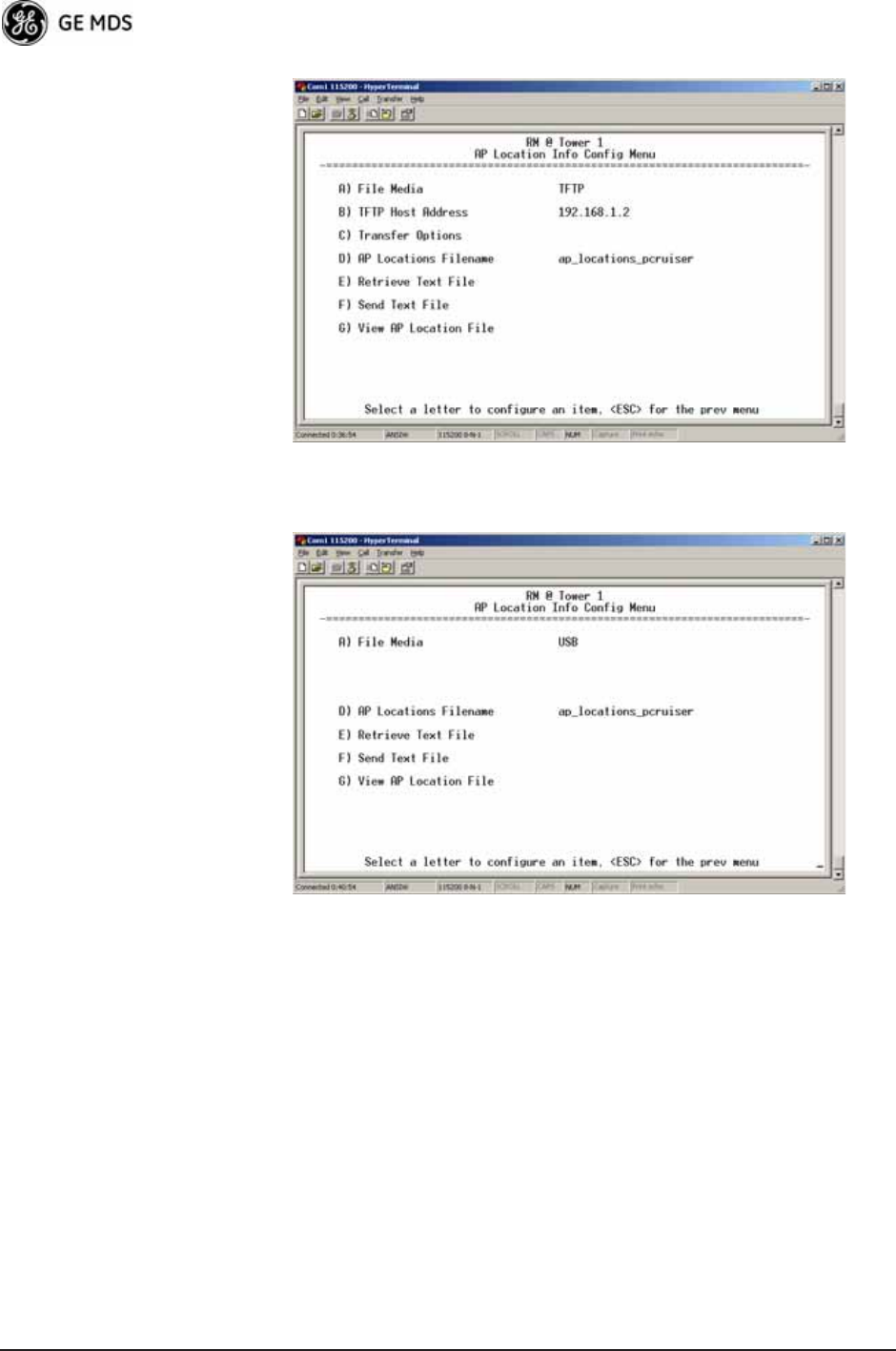
60 Mercury Reference Manual 05-4446A01, Rev. D
Invisible place holder
Figure 3-27. AP Location Info Configuration Menu, TFTP Mode
(Firmware version 3.0 only)
Invisible place holder
Figure 3-28. AP Location Info Configuration Menu, USB Mode
(Firmware version 3.0 or later)
•File Media—A selection of methods for transferring files to and
from the radio available on firmware version 3.0 radios. The
options are: TFTP and USB.
•TFTP Host Address—IP address of the TFTP server that holds the
AP locations file. [any valid IP address; 0.0.0.0]
•Transfer Options—Menu for configuring the TFTP transfer.
•AP Locations Filename—Name of the AP Locations file on the
server. [any valid filename string; ap_locations.txt]
•Auto AP Location Download—A setting to force connected remotes
to download immediately the AP Locations file on the AP.
Remotes that associate to an AP with this feature will also
download the file.
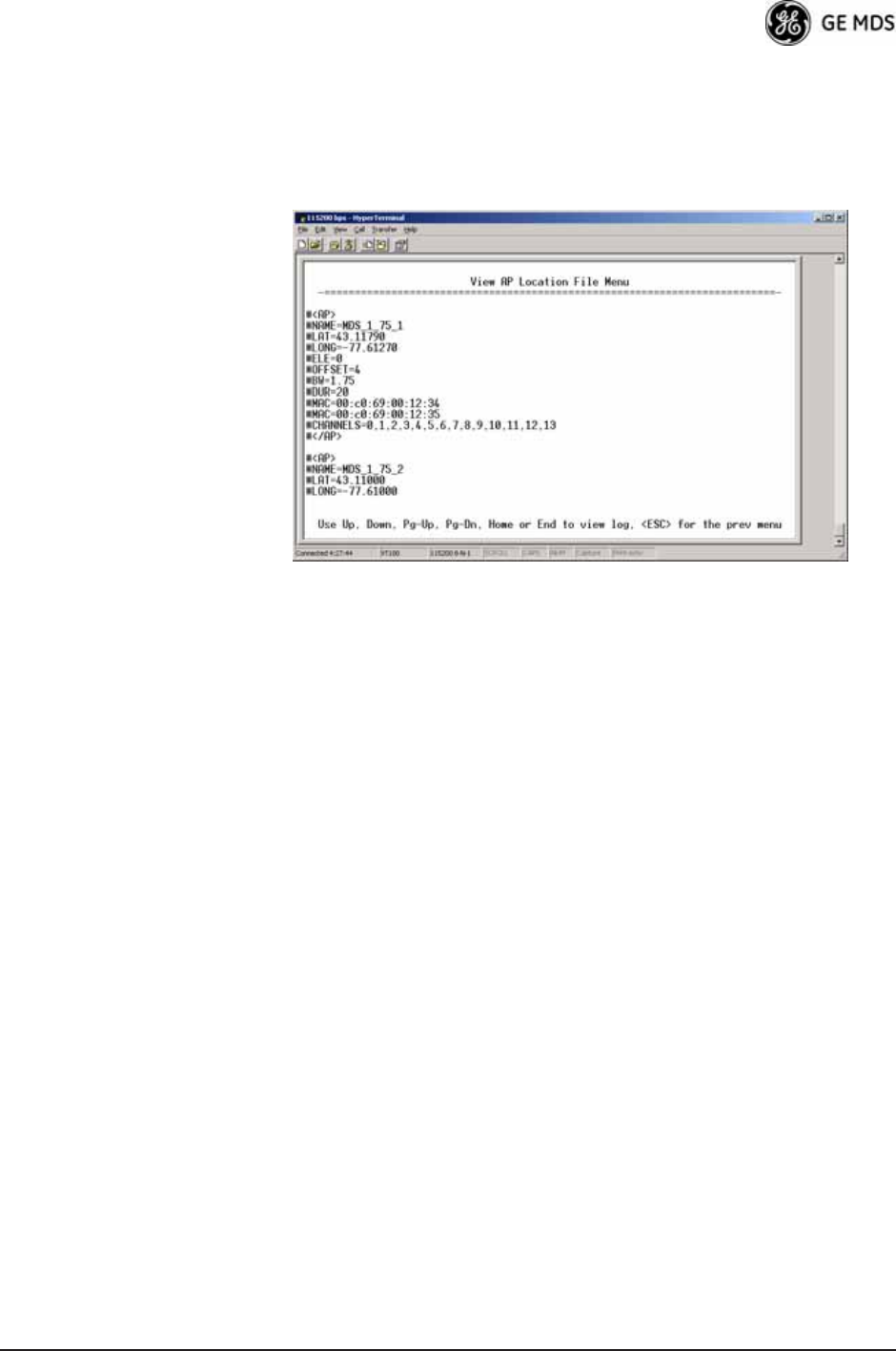
05-4446A01, Rev. D Mercury Reference Manual 61
•Retrieve Text File—Download AP Locations text file from the
server.
•Send Text File—Upload the local AP Locations file to the server.
•View AP Location File—Allows on-screen review of the AP Loca-
tions file. An example screen is shown in Figure 3-29.
Invisible place holder
Figure 3-29. AP Location Text File
AP Locations File Syntax and Guidelines
The AP Locations file is used by the Remote radio to determine which
Access Point to connect to when operating in Hopping w/ Hand-offs mode.
The AP Locations file is a simple text file containing information about
the location and configuration of all Access Points that the Remote can
associate with. The file is filled in by creating “AP definition blocks”
using tags and labels. The <AP> tag is used to begin a definition block
and the </AP> tag ends the block. Within the block, you can declare sev-
eral parameters using a LABEL=VALUE syntax. The possible labels
are:
•NAME—The name of the AP. Typically set to the Device Name
configured on the AP
•LAT—GPS Latitude of the AP in decimal degrees
•LONG—GPS Longitude of the AP in decimal degrees
•OFFSET—Pattern Offset configured on the AP
•BW—Bandwidth configured on the AP
•DUR—Frame duration (10 or 20) configured on the AP
•MAC—The “Wireless MAN Address” configured on the AP
•CHANNELS—Specifies which channels are being used by the AP
•GROUP—Name of a grouping of Access Points. A Remote con-
figured with Eth Follows Association enabled does not disable its
wired port when moving between APs of the same group.This
is useful when two or more APs are on the same subnet.
•MODE—Single or Hopping. Specifies the Frequency Mode of the
AP.

62 Mercury Reference Manual 05-4446A01, Rev. D
•SINGLE_CHAN—Specifies the AP’s Single Frequency mode
channel.
The MAC label may appear twice if a P23 redundant Access Point is
installed at that location. In this case, one MAC statement provides the
MAC address of the A radio and the other MAC statement provides the
MAC address of the B radio. The CHANNELS statement only needs to be
present if the channel selection feature is used at the Access Point to
limit which channels are active. If all channels are used, you can leave
out the CHANNELS statement. You can leave out the BW statement for
APs that are configured to 1.75 MHz bandwidth. You can also leave out
the DUR statement for APs that are configured with a 20 millisecond
frame duration.
NOTE: MAC filtering on APs should be used only in a stable network
or with the complete understanding that devices not listed in
the AP filter will not gain access to the Remotes, nor be acces-
sible to the Remotes.
The following shows the syntax of the AP Locations file:
# Mercury Remote AP Locations file
# These lines are comments
# The following line defines the beginning of an AP definition block
<AP>
NAME=MyAccessPoint
LAT=43.11790
LONG=-77.61270
OFFSET=3
BW=1.75
DUR=20
MAC=00:06:3D:00:01:23
CHANNELS=1,3,5,7,9,11,13
# The following line defines the end of the AP definition block
</AP>
3.4.6 SNTP Server Configuration
The Simple Network Time Protocol (SNTP) allows the Mercury to
obtain time of day data from a network server.
NOTE: The Mercury can also obtain time of day data from the GPS
receiver, if the receiver has a satellite fix.
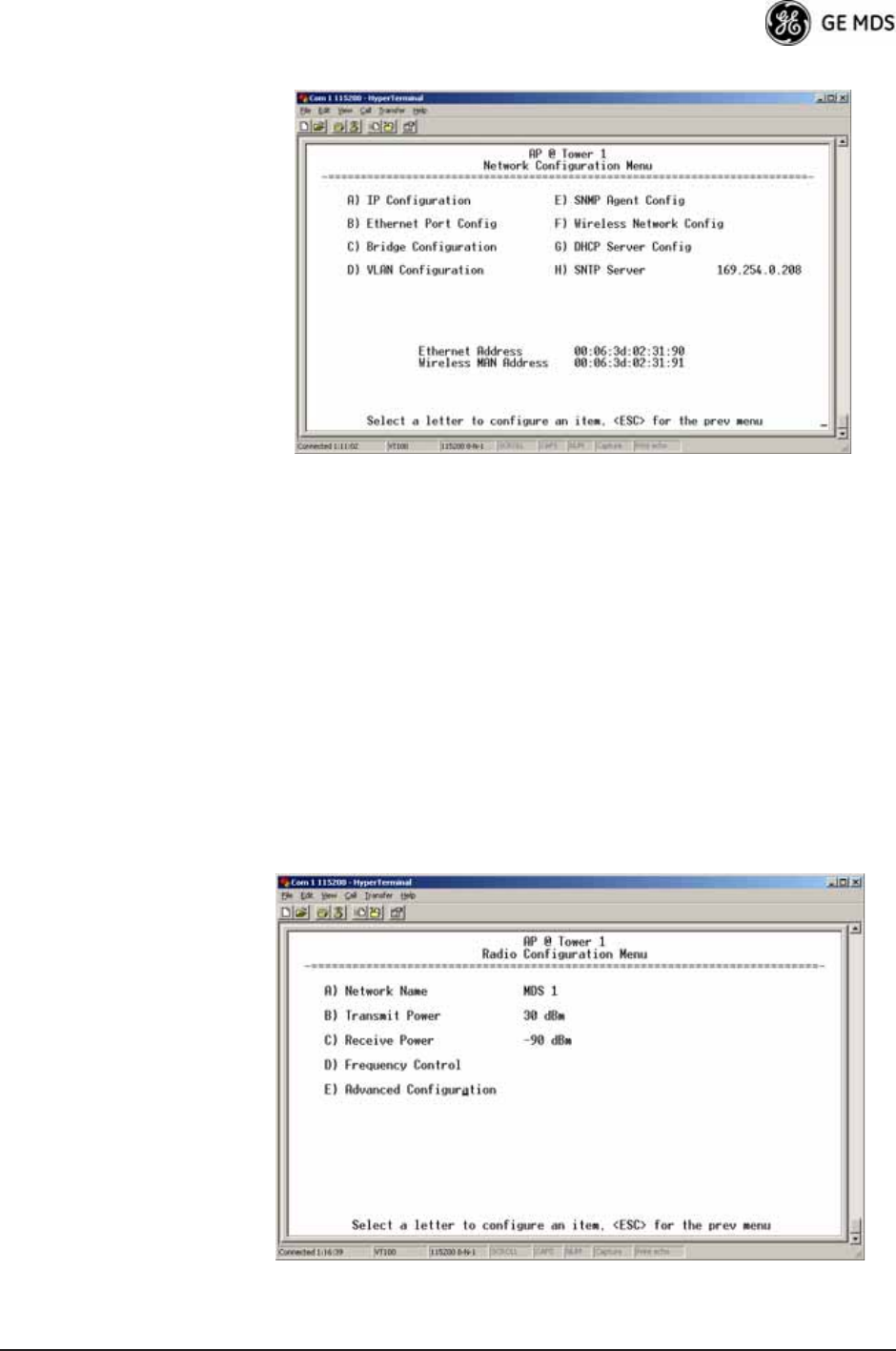
05-4446A01, Rev. D Mercury Reference Manual 63
Invisible place holder
Figure 3-30. SNTP Server Entry (on Network Configuration Menu)
When SNTP Server is selected (item H), the area to the right of the param-
eter becomes active, allowing you to enter a valid SNTP server address.
Press the Return key to make the address entry active.
3.5 RADIO CONFIGURATION
There are two primary layers in the transceiver network—radio and
data. Since the data layer is dependent on the radio layer working prop-
erly, configure and set the radio items before proceeding. This section
explains the Radio Configuration Menu, (Figure 3-31 for AP,
Figure 3-32 for Remote).
3.5.1 Radio Configuration Menu
Figure 3-31. Radio Configuration Menu
(From Access Point)
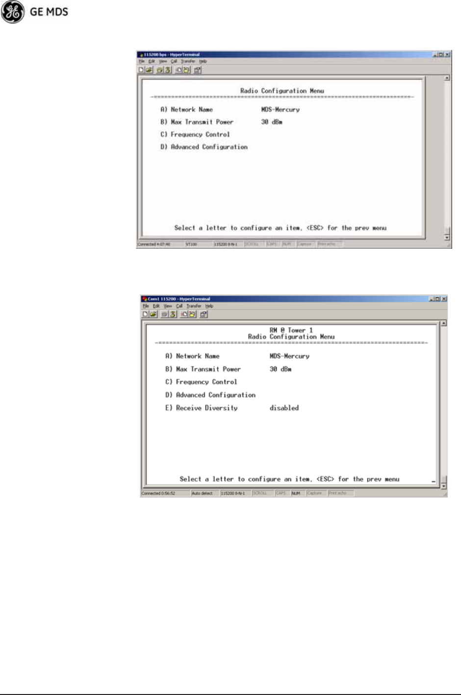
64 Mercury Reference Manual 05-4446A01, Rev. D
Figure 3-32. Radio Configuration Menu
(From Remote Unit)
Invisible place holder
Figure 3-33. Radio Configuration Menu
(From Option Set 1 Remote)
•Network Name—The user-defined name for the wireless network.
[Any 40 character string; MDS-Mercury]
•Transmit Power (AP Only)—Sets/displays RF power output level
in dBm. This setting should reflect local regulatory limitations
and losses in antenna transmission line. (See “How Much Out-
put Power Can be Used?” on Page 167 for information on how
to calculate this value.) [0—30; 30 (900 model)] [0—23; 23 (3650 model)]
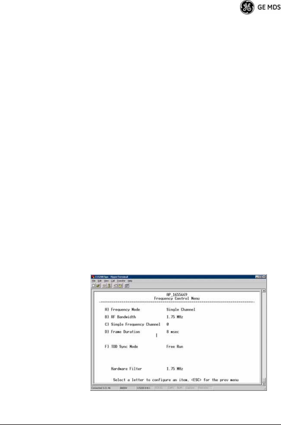
05-4446A01, Rev. D Mercury Reference Manual 65
•Max Transmit Power (Remote Only)—Sets/displays maximum RF
power output level in dBm of the Remote. Power level is still
controlled by the AP, but it is limited to the maximum level set
here. This setting should reflect local regulatory limitations and
losses in antenna transmission line. (See “How Much Output
Power Can be Used?” on Page 167 for information on how to
calculate this value.) [0—30; 30 (900 model) 0—23; 23 (3650 model)
•Receive Power (AP Only)—View/set the receiver gain setpoint
for the expected strength of incoming signals from Remotes.
This setting indicates at what level (in dBm) the AP expects to
hear the Remote stations. A setting of -70 would set the AP
receiver’s gain to a relatively low level, while a setting of -85
would be a comparatively high gain setting. [-100 to -20; -75]
•Frequency Control—Opens a submenu where you can view or set
frequency mode bandwidth, channel and other parameters as
described in Frequency Control Menu below.
•Advanced Configuration—Opens a submenu where you can view
or set modulation, protection/hysteresis margins, data compres-
sion, ARQ settings, and other parameters as described in
Advanced Configuration Menu on Page 72.
•Receive Diversity (900 MHz Remote Only)—Allows enabling or
disabling the RX2 antenna port for receive operation. The use of
two antennas allows “diversity” reception which helps mini-
mize the effects of fading due to multipath reception of signals.
Frequency Control Menu
The items shown on this menu vary depending on the Frequency Mode
Selection (Single Channel, Static Hopping, Hopping w/Hand-offs). Examples
of all three screens are provided below, followed by a description of the
menu items.
Invisible place holder
Figure 3-34. Frequency Control Menu
(900 MHz AP, Single Channel Freq. Mode)
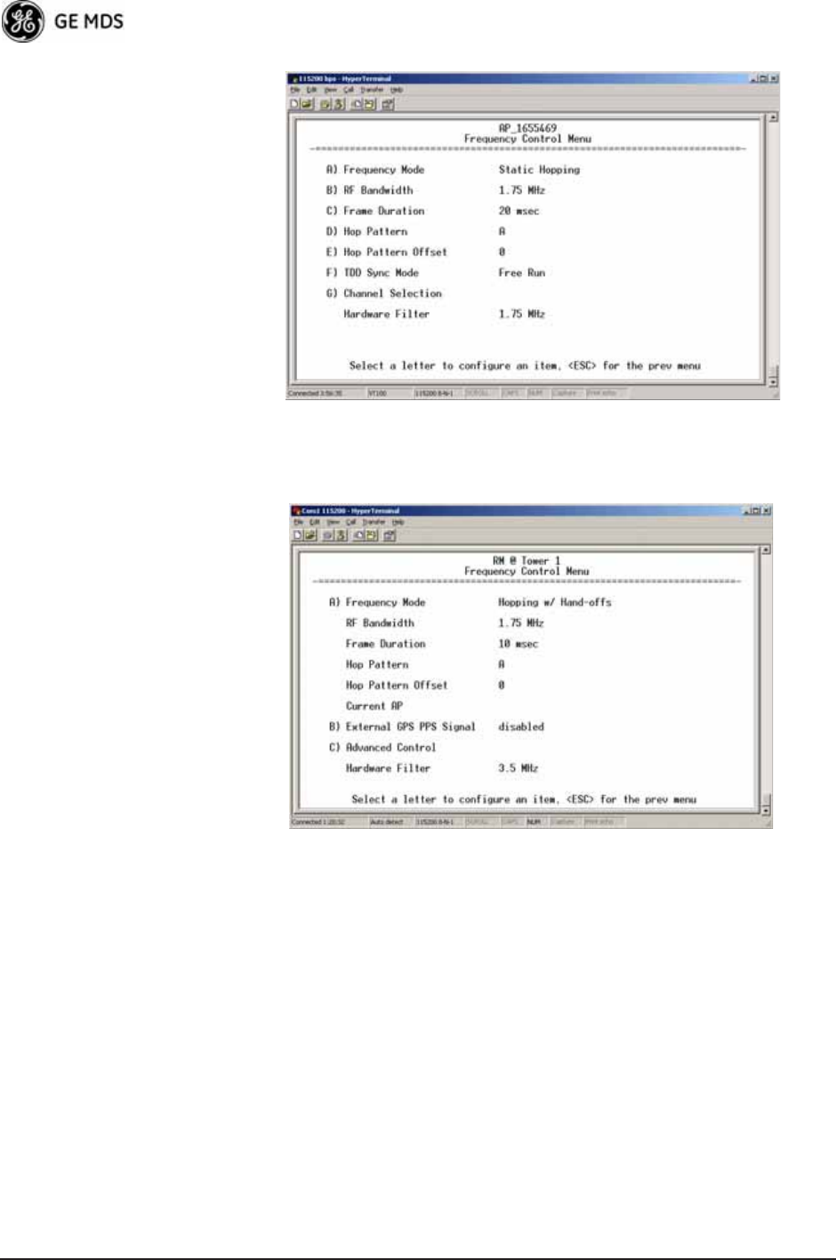
66 Mercury Reference Manual 05-4446A01, Rev. D
Invisible place holder
Figure 3-35. Frequency Control Menu
(900 MHz AP, Static Hopping Freq. Mode)
Figure 3-36. Frequency Control Menu
(900 MHz Remote, Hopping w/Hand-offs Freq. Mode)