GE MDS DS-MERCURY900 Mercury 900 Wireless Transceiver User Manual
GE MDS LLC Mercury 900 Wireless Transceiver
GE MDS >
Contents
- 1. manual pt 1
- 2. manual pt 2
- 3. User Manual 1
- 4. User Manual 2
- 5. Users Manual Revised 121908 Part 1
- 6. Users Manual Revised 121908 Part 2
- 7. Users Manual Revised 121908 Part 3
Users Manual Revised 121908 Part 2

05-4446A01, Rev. D Mercury Reference Manual 67
Invisible place holder
Figure 3-37. Frequency Control Menu
(Mercury 3650 model only)
•Frequency (Mercury 3650 only)—Used to set/display the radio’s
operating frequency. MDS 3650 radios do not employ fre-
quency hopping, thus the entry here is a specific RF operating
channel. The allowable entry range is 3650.000000 to 3700.000000
MHz.
•Frequency Mode—The unit can operate on one selected fre-
quency or frequency hop. Remotes have the option of using a
static hopping configuration or using the AP locations file to
select an AP and perform hand-offs. For more information on
hand-offs, see Table 3-2 on Page 70. Changing this parameter
requires a radio reboot.
[Static Hopping, Hopping with Hand-offs, Single Channel;
Single Channel]
NOTE: Frequency Mode Static Hopping on Access Points requires
TDD Sync Mode GPS Required.
Channel/Frequency Allocations for Single Channel 900 MHz
are shown in Table 3-1. The transceiver uses up to 14 channels
(0-13) depending on the bandwidth used (1.75 MHz or 3.5
MHz).
Table 3-1. Channel/Frequency Allocations
Channel 1.75 MHz B/W 3.5 MHz B/W
0 903.000000 904.000000
1 904.800000 907.600000
2 906.600000 911.400000
3 908.600000 915.000000
4 910.400000 918.600000
5 912.200000 922.400000
6 914.000000 926.000000

68 Mercury Reference Manual 05-4446A01, Rev. D
•RF Bandwidth—View/set the radio’s RF operating bandwidth.
Radios are factory-configured for either 1.75 MHz or 3.5
MHz maximum bandwidth. Determine the factory configu-
ration of a radio by viewing the “CONFIG” number on the
label at the bottom of the radio. 1.75 MHz units will have a
Configuration string starting with HGA/R9N1, and 3.5 MHz
units will have a string starting with HGA/R9N3.
The bandwidth setting on this menu does not necessarily
have to match the configured bandwidth of the radio, but it is
limited by it. That is, you can set a 3.5 MHz radio to either
1.75 or 3.5, but you can only set a 1.75 MHz radio to 1.75.
Note that setting a 3.5 MHz bandwidth radio to operate at
1.75 MHz bandwidth will cause a slight degradation of inter-
ference rejection capability. Note that this parameter is
read-only when Frequency Mode is set to Hopping w/Hand-offs.
[1.75MHz, 3.5MHz]
The Mercury 3650 can operate at 1.75 MHz, 3.5 MHz, 5
MHz, or 7 MHz bandwidth. The unit uses a digital filter so
that any unit can operate at any bandwidth.
•Single Frequency Channel—The RF frequency that the inte-
grated radio will operate on when in single frequency
(non-hopping) mode. [0 to 6 for 3.5-MHz, 0 to 13 for 1.75-MHz; 0].
•Frame Duration—Defines the over-the-air media access con-
trol framing. Note that this parameter is read-only when Fre-
quency Mode is set to Hopping w/Hand-offs. [5, 8, 10, or 20 msec;
20 msec]
•Hop Pattern—Selects a pre-defined series of channels that is
followed when hopping. Note that this parameter is read-only
when Frequency Mode is set to Hopping w/Hand-offs.
•Hop Pattern Offset—Inserts an offset into the hop pattern that
is synchronized with the GPS. For example, if the offset is 0,
the start of the pattern is aligned with the GPS timing. If the
offset is 3, then the fourth hop of the pattern is aligned with
the GPS timing. All of the APs that are part of a network
should use the same pattern and each one should have its own
offset.
7 916.000000
8 917.800000
9 919.600000
10 921.400000
11 923.400000
12 925.200000
13 927.000000
Table 3-1. Channel/Frequency Allocations (Continued)
Channel 1.75 MHz B/W 3.5 MHz B/W
05-4446A01, Rev. D Mercury Reference Manual 69
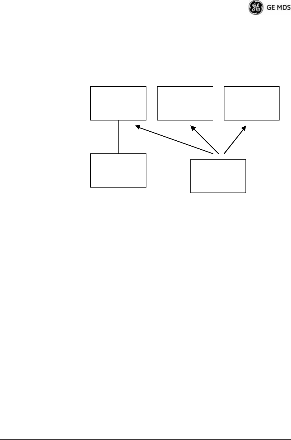
In the diagram below, one Remote is configured for static
hopping and will only associate with AP1 because they are
both using Offset 0. The hand-off configured Remote, using
its AP Locations file, may connect to AP1, AP2, or AP3. The
Remote does this by determining the Offset for each AP, then
configuring its radio.
•Current AP (Remote only)—Shows the name of the AP that
the Remote is trying to associate with. Note that this param-
eter is read-only when Frequency Mode is set to Hopping
w/Hand-offs.
•TDD Sync Mode (AP only)—Indicates if the Access Point’s trans-
missions should synchronize with the GPS timing. Configure
this parameter to GPS Required when the AP is configured for
Static Hopping. TDD Sync Mode (Time-Division Duplex) is use-
ful in eliminating same-network interference for multiple-AP
installations. When enabled, all AP transmissions are synchro-
nized using GPS timing information. The result is that no AP
transmits while another is receiving, which prevents AP-to-AP
interference. Changing this parameter requires a radio reboot.
[Free Run, GPS Required; Free Run] Note: Do not use the Prefer GPS
setting.
•Channel Selection (AP only)—Opens a submenu where you can
specify channel usage.
•External GPS PPS Signal—Indicates whether or not an external
Pulse Per Second (PPS) signal is available. The setting may be
changed by pressing the spacebar after selection of the menu
item. This allows the radio to use the proper timing scheme
when frequency hopping.
•Advanced Control (Remote only)—Brings up a submenu (see
Figure 3-38) where additional communication parameters may
be set.
AP 1
Pattern A
Offset 0
AP 2
Pattern A
Offset 1
AP 3
Pattern A
Offset 2
RM
Static Hopping
Offset 0
RM
Hopping w/
Hand-offs

70 Mercury Reference Manual 05-4446A01, Rev. D
•Hardware Filter (900 MHz only)—This field provides a read-only
indication of the maximum bandwidth of the radio. [1.75 MHz or
3.5 MHz]
Hand-Off Mode
Parameters In a mobile or portable application, a Remote radio can move and asso-
ciate with different APs depending on its location. The process by which
the Remote ends the connection with one AP and begins a connection
with another AP is called “hand-off.” Table 3-2 lists the hand-off
parameters for Remote transceivers and explains how they operate
under different signal conditions.
NOTE: In Table 3-2 above, modes using the “Closest 3 APs” first
attempt to connect to the closest AP. If after the maximum
number of scanning seconds (Max. Scanning Seconds) a link is
not established, then the next closest AP is chosen. If after
another maximum number of scanning seconds a link is not
established, then the third closest AP is chosen. If a link still is
not established, the Remote again chooses the closest AP and
continues this cycle until it is associated to one of the APs.
NOTE: In Table 3-2 above, modes which use the RSSI and SNR Thresh-
olds use them in an “or” logic fashion. That is, if the RSSI is
below the set threshold OR the SNR is below threshold, the
Remote drops the current AP.
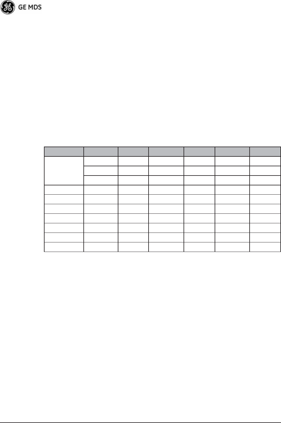
Table 3-2. Remote Hand-Off Parameters
Strict
Distance
Strict
Connection
Strict
Signal
Signal and
Distance
Signal, Dis-
tance, and
Bearing
Description The Remote
always chooses
the closest AP
regardless of
connection
status, RSSI,
etc.
The Remote will
only choose a
new AP when
the modem link
is lost.
The Remote
chooses a new
AP when the
modem link is
lost or when the
RSSI or SNR
falls below the
threshold. The
Remote then
chooses the
closest AP.
Operates the
same way as the
Strict SIgnal
method except
that the current
AP is abandoned
only if the next
AP is within the
distance
threshold.
Operates the
same way as the
Signal and
Distance method
except that the
current AP is
abandoned only
if the bearing is
away from the
current AP.
AP(s) Used
(see note be-
low Table 3-2)
Only closest AP. Closest 3 APs. Closest 3 APs. Closest 3 APs;
AP must be
within Distance
Threshold.
Closest 3 APs;
AP must be
within Distance
Threshold.
Max. Scanning
Seconds
N/A Applicable Applicable Applicable Applicable
RSSI
Threshold
N/A N/A Applicable Applicable Applicable
SNR Threshold N/A N/A Applicable Applicable Applicable
Distance
Threshold
N/A N/A N/A Applicable Applicable
Blacklist Time N/A Applicable Applicable Applicable Applicable
05-4446A01, Rev. D Mercury Reference Manual 71
Advanced Control Menu Invisible place holder
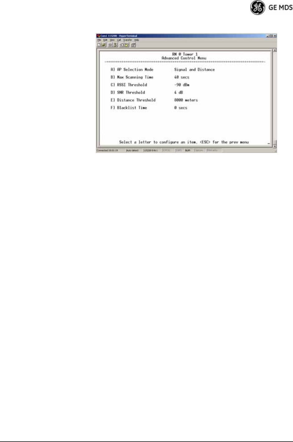
Figure 3-38. Advanced Control Menu
(Hopping with Handoff Mode, Remote Only)
AP Selection Mode—The method used by the Remote to determine what
AP to connect to. It may be based on Signal, Distance and Bearing (from
the AP's GPS coordinates in the AP locations file), or Connection.
Table 3-2 on Page 70 summarizes these parameters and other selections
on this menu.
Max Scanning Time—The maximum time to try to connect to an AP before
trying the next one in the AP Locations file.
RSSI Threshold—The RSSI cutoff for Signal modes. When the RSSI drops
below this value, the Remote disconnects and looks for a new AP.
SNR Threshold—The SNR cutoff point for Signal modes. When the SNR
drops below this value, the Remote disconnects and looks for a new AP.
Distance Threshold—The distance cutoff when operating in Distance
mode. When the Remote's AP gets farther away than this distance, it dis-
connects and look for a new AP.
Blacklist Time—The amount of time (in seconds) that an AP is ignored
when the Remote is trying to find a better connection.
72 Mercury Reference Manual 05-4446A01, Rev. D
Advanced Configuration Menu Invisible place holder
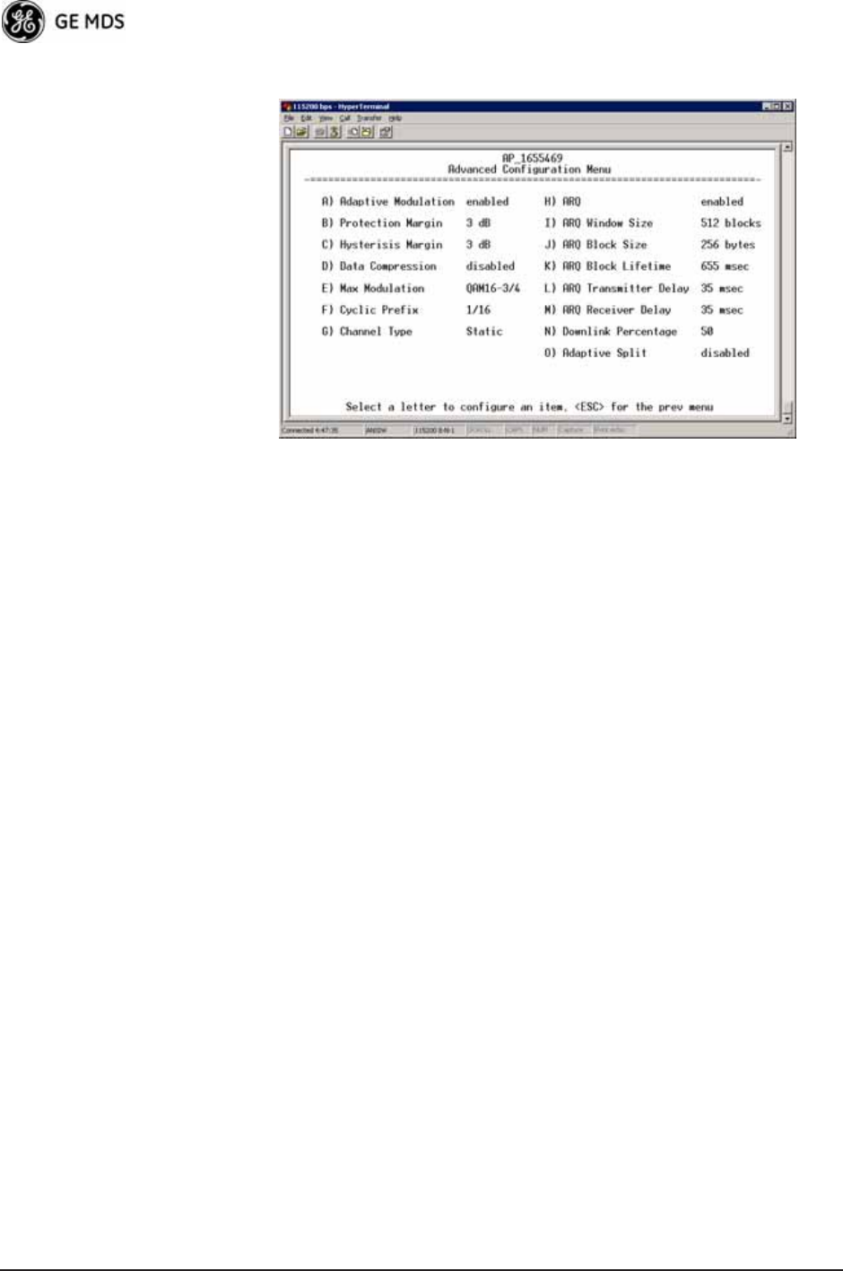
Figure 3-39. Advanced Configuration Menu
•Adaptive Modulation—Enables automatic selection of modulation
and FEC rate based on SNR. [enabled, disabled; enabled]
•Protection Margin—A number of decibels of SNR added to the
minimum SNR required for a given modulation and FEC rate.
See “Modulation Protection and Hysteresis Margins” on
Page 73 for more information. [0-50; 3]
•Hysteresis Margin—A number of decibels of SNR added to the
maximum SNR required before shifting to the next higher mod-
ulation and FEC rate. See “Modulation Protection and Hyster-
esis Margins” on Page 73 for more information. [0-50; 3]
•Data Compression—This setting determines whether over-the-air
data packets will be compressed. [enabled, disabled; enabled]
•Max Modulation—Sets the highest modulation speed the trans-
ceiver will use.
[BPSK, QPSK-1/2, QPSK-3/4, 16QAM-1/2, 16QAM-3/4, 64QAM-2/3;
QAM16-3/4]
•Cyclic Prefix (AP only)—Amount of additional information
added to the over-the-air packets to mitigate the effects of chan-
nel multipath. [1/4, 1/8, 1/16,1/32; 1/16]
•Channel Type (AP only)—This parameter, available on Access
Point units, must be set appropriately according to the signal
conditions of a network. For installations with strong signals,
low interference, and minimal fading, set the Channel Type
parameter to Static. This setting is generally appropriate for
Access Points whose Remotes are in fixed locations. It supports
a large offered payload with high packet rates.
For installations with significant interference and fading or
nomadic/mobile Remotes, set the Channel Type parameter to
Dynamic. [Static, Dynamic; Static]

05-4446A01, Rev. D Mercury Reference Manual 73
•ARQ (AP only)—Enables the Automatic Repeat Request func-
tion.
[enable, disable; enabled]
•ARQ Window Size (AP only)—The maximum number of blocks to
send before receiving an acknowledgement. [1—1024; 512]
•ARQ Block Size (AP only)—ARQ is applied to payload data in
blocks of this size. [4—2040; 256]
•ARQ Block Lifetime (AP only)—ARQ blocks are valid for this
length of time. [0—655; 655]
•ARQ Transmitter Delay (AP only)—The length of time the trans-
mitter waits before repeating an unacknowledged packet.
[1—655; 35]
•ARQ Receiver Delay (AP only)—The length of time the receiver
waits before repeating an unacknowledged packet. [1—655; 35]
•Downlink Percentage (AP only)—The percentage of link time
given to downstream traffic. It should be set to 50% when Adap-
tive Split is set to enabled. [10-90%; 50%]
•Adaptive Split (AP only)—The adaptive split feature provides
improved link utilitization and throughput for burst payload
traffic. The Mercury is a TDD system and normally allocates
50% of its capacity to the downlink and 50% to the uplink.
When adaptive split is enabled, the Media Access Controller
(MAC) in the Access Point monitors the traffic flow continu-
ously in the downlink and uplink directions. The MAC automat-
ically modifies the downlink split in response to the traffic load.
When more traffic is flowing upstream, the downlink split
changes to allocate additional capacity to the uplink. When
more traffic is flowing downstream, the downlink gets addi-
tional capacity. If TDD synchronization is used to synchronize
Access Points and minimize inter-Access Point interference,
Adaptive Split should be disabled. [enabled, disabled; enabled]
Modulation
Protection and
Hysteresis Margins
Table 3-3 on Page 74 shows the relationship between the radio’s Protec-
tion Margin, Hysteresis Margin, and the SNR range allowed for each
form of modulation.
Column A lists the available modulation types for the radio, while col-
umns B and C show the minimum SNR range required to operate in each
modulation. For example, an SNR of 5.8 dB in Column B is required for
QPSK modulation with an FEC rate of 1/2. An SNR of 8.4 dB is
required for QPSK modulation with an FEC rate of 3/4.
Columns B and C have a Hysteresis Margin of 0 dB. This means there
is no overlap between the maximum SNR for BPSK (5.8 dB) and the
minimum SNR for QPSK-1/2 (5.8 dB).
Columns D and E show the SNR ranges with a Protection Margin and
Hysteresis Margin of 3 dB. The Protection Margin is added to each
value in Columns B and C to get the corresponding value in Columns D
and E. The Hysteresis Margin is then added to the Max SNR value.
74 Mercury Reference Manual 05-4446A01, Rev. D
For example, the third SNR value in Column D is 11.4 dB (8.4 + 3 =
11.4 dB), and the third SNR value in Column E is 17.1 (11.1 + 3 + 3 =
17.1 dB). Note that with a Hysteresis Margin of 3 dB, there is an overlap
of 3 between the Max SNR of one modulation and the Min SNR of the
next higher modulation.
In this case, if a link is operating with an SNR of 15 dB, then QPSK-3/4
modulation is used. The SNR must go above 17.1 dB before the link
shifts up to 16QAM-1/2 modulation. Conversely, the SNR will need to
drop below 11.4 dB before the link shifts down to QPSK-1/2.
The blank entries (--) in the table indicate infinite SNR (i.e., the top of
the range). For example, in columns B and C, 64QAM-3/4 modulation
is used for all SNR values from 20 dB and up.
3.5.2 Serial Port Configuration
Overview
The transceiver includes an embedded serial device server that provides
transparent encapsulation over IP. In this capacity, it acts as a gateway
between serial and IP devices. Two common scenarios are PC applica-
tions using IP to talk to remote devices, and serial PC applications
talking to remote serial devices over an IP network. These data services
are available from the COM1 port of the radio.
COM1 Port—Dual
Purpose Capability The COM1 port is used as a local console connection point and to pass
serial data with an external device. Setting the COM1 port status to Enable
prevents access to the Management System (MS) through this port.
However, the MS can still be accessed via the LAN port using Telnet or
a web browser.
Table 3-3. Adaptive Modulation Protection and Hysteresis Margins
A B C D E F G
Protection 0 Protection 3 Protection 5
Hysteresis 0 Hysteresis 3 Hysteresis 3
Min SNR Max SNR Min SNR Max SNR Min SNR Max SNR
BPSK 3.3 5.8 3.3 11.8 3.3 13.8
QPSK-1/2 5.8 8.4 8.8 14.4 10.8 16.4
QPSK-3/4 8.4 11.1 11.4 17.1 13.4 19.1
16QAM-1/2 11.1 14.4 14.1 20.4 16.1 22.4
16QAM-3/4 14.4 18.4 17.4 24.4 19.4 26.4
64QAM-2/3 18.4 20 21.4 26 23.4 28
64QAM-3/4 20 -- 23 -- 25 --

05-4446A01, Rev. D Mercury Reference Manual 75
NOTE: To restore the COM1 port to support Management System
services, connect a terminal to the port, select the proper baud
rate (115,200 is default), and enter an escape sequence (+++) to
reset it to the console mode.
There is a configuration parameter for the console baud rate and
another parameter for the serial data baud rate. These items can
be different, so when switching out of data mode to console
mode, the port might also change its baud rate.
TCP vs. UDP TCP and UDP services are used by the transceiver’s embedded serial
device server. TCP provides a connection-oriented link with end-to-end
acknowledgment of data, but with some added overhead. UDP provides
a connectionless best-effort delivery service with no acknowledgment.
Most polled protocols are best served by UDP service as the protocol
itself has built-in error recovery mechanisms. UDP provides the needed
multidrop operation by means of multicast addressing.
On the other hand, TCP services are best suited for applications without
a recovery mechanism (error-correction) and must have the guaranteed
delivery that TCP provides in spite of the extra overhead. The
IP-to-Serial Application Example on Page 81 shows how to do this.
Serial Encapsulation Transparent encapsulation, or IP tunneling, provides a mechanism to
encapsulate serial data in an IP envelope. All bytes received through the
serial port are put into the data portion of a TCP or UDP packet (TCP or
UDP are user-configurable options). In the same manner, all data bytes
received in a TCP or UDP packet are output through the serial port.
When the radio receives data through the serial port, it is buffered until
the packet is received completely. There are two events that signal an
end-of-packet to the radio: a period of time since the last byte was
received, or a number of bytes that exceed the buffer size. Both of these
triggers are user-configurable.
One radio can perform serial data encapsulation (IP-to-Serial) and talk
to a PC. You can use two radios together (or one radio and a terminal
server) to provide a serial-to-serial channel. For more information, see
“IP-to-Serial Application Example” on Page 81 and Point-to-Point
Serial-to-Serial Application Example on Page 82.
TCP Client vs. TCP
Server On a TCP session there is a server side and a client side. You can con-
figure the transceiver to act as either a server or a client. The server
always waits for requests from clients.
The client mode attempts to establish a connection to a server (typically
running on a PC) whenever it receives data on the serial port. There is
also a Client/Server mode, where the client establishes a connection
when data is received on the serial port and the server is not currently
handling a connection.
76 Mercury Reference Manual 05-4446A01, Rev. D
UDP Multicast IP provides a mechanism to perform a limited broadcast to a specific
group of devices. This is known as multicast addressing. Multicast
addressing requires the use of a specific branch of IP addresses set apart
by the Internet Assigned Numbers Authority (IANA) for this purpose.
UDP multicast is generally used to transport polling protocols typically
used in SCADA applications where multiple remote devices will
receive and process the same poll message.
As part of the Multicast implementation, the radio sends IGMP mem-
bership reports and IGMP queries, and responds to membership queries.
It defaults to V2 membership reports, but responds to both V1 and V2
queries.
The Point-to-Multipoint Serial-to-Serial Application Example on
Page 83 shows how to provide multicast services.
Data Buffering Data buffering is always active regardless of the selected mode. If you
connect EIA-232 serial devices to the transceiver, review these parame-
ters carefully.
Serial Configuration Wizard
GE MDS recommends the Serial Configuration Wizard, available
through the Serial Port Configuration Menu, for configuration of the serial
terminal services. The wizard uses a step-by-step process, eliminates
possible conflicting settings, and streamlines complex configurations.
You can bypass the wizard by selecting option B) View Current Settings
and adjusting the individual settings of the appropriate parameter.
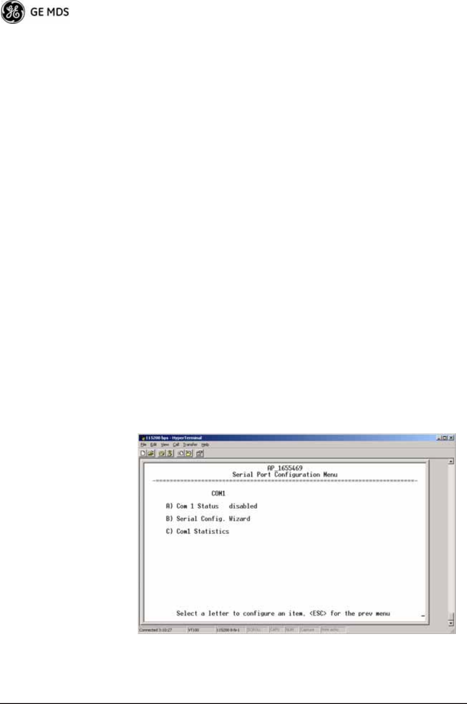
Serial Port
Configuration Menu Invisible place holder
Figure 3-40. Serial Port Configuration Menu
05-4446A01, Rev. D Mercury Reference Manual 77
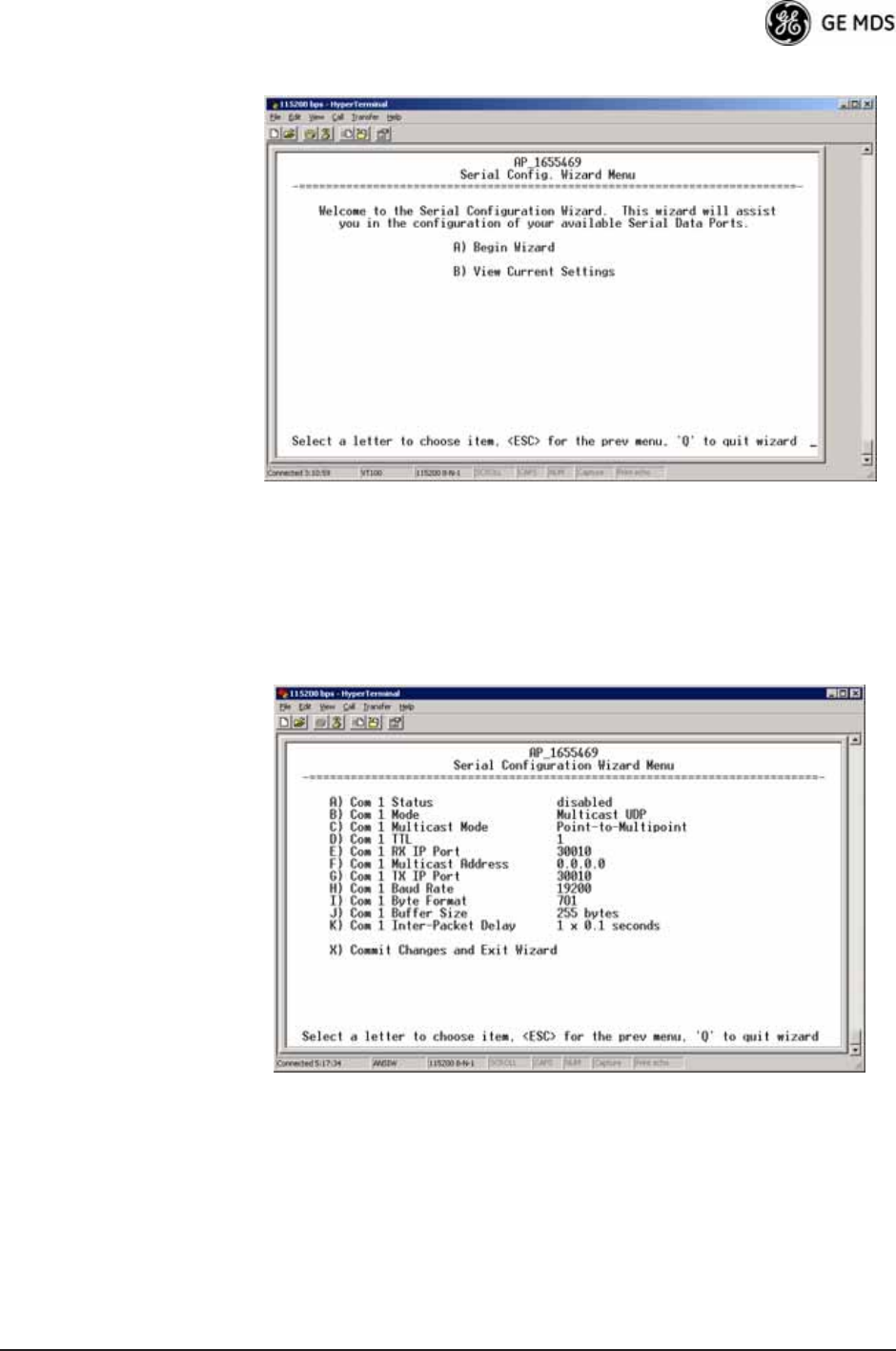
Figure 3-41. Serial Configuration Wizard
•Begin Wizard—Tool for configuring serial ports using a
step-by-step process.
•View Current Settings—Displays all setable options. Varies
depending on the selected IP protocol.
Configuring for UDP
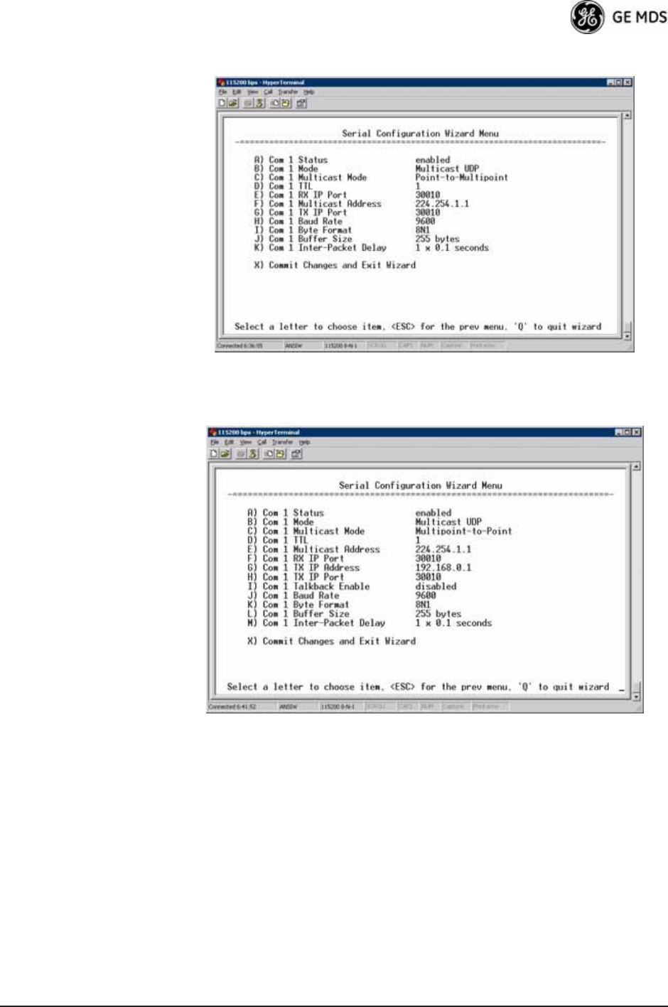
Point-to-Multipoint Invisible place holder
Figure 3-42. UDP Point-to-Multipoint Menu
Use UDP point-to-multipoint to send a copy of the same packet to mul-
tiple destinations, such as in a polling protocol.
•Status—Enable/Disable the serial data port.
•Mode—The type of IP port offered by the transceiver’s serial
device server. [TCP, UDP; TCP]
78 Mercury Reference Manual 05-4446A01, Rev. D
•RX IP Port—Receive IP data from this source and pass it
through to the connected serial device. The port number must
be used by the application connecting to local TCP or UDP
socket. [Any valid IP port; 30010]
•TX IP Address (used instead of Local IP Address when using
UDP Point-to-Multipoint)— Configure with a valid Multi-
cast address (224.0.0.0–239.255.255.255). IP packets
received with a matching destination address are processed
by this unit. [Any legal IP address; 0.0.0.0]
•TX IP Port (used instead of Local IP Port when using UDP
Point-to-Multipoint)—This port number must match the
number used by the application connecting to local TCP or
UDP socket. [1-64,000; 30010]
•Baud Rate—Data rate (payload) for the COM port, in
bits-per-second. [1,200—115,200; 19200]
•Byte Format—Formatting of data bytes, representing data bits,
parity and stop bits. [7N1, 7E1, 7O1, 8N1, 8E1, 8O1, 8N1, 7N2, 7E2,
7O2, 8N2, 8E2, 8O2; 8N1]
•Buffer Size—Maximum amount of characters that the Remote
end buffers locally before transmitting data through the serial
port. [1—255; 255]
•Inter-Packet Delay—Amount of time that signal the end of a
message, measured in tenths of a second. [default = 1 (that is,
1/10th of a second)]
•Commit Changes and Exit Wizard—Save and execute changes
made on this screen (shown only after changes have been
entered). Invisible place holder
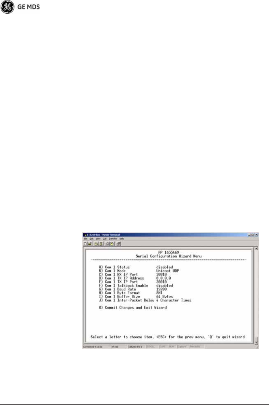
Figure 3-43. UDP Point-to-Point Menu
Configuring for UDP
Point-to-Point Use UDP point-to-point configuration to send information to a single
device.
•Status—Enable/Disable the serial data port.

05-4446A01, Rev. D Mercury Reference Manual 79
•Mode—UDP Point-to-Point. This is the type of IP port
offered by the transceiver’s serial device server.
[TCP, UDP; TCP]
•RX IP Port—Port number where data is received and passed
through to the serial port. The application connecting to this
transceiver must use this port number.
[1—64,000; 30010]
•TX IP Address—Data received through the serial port is sent to
this IP address. To reach multiple Remotes in the network,
use UDP Point-to-Multipoint.
[Any legal IP address; 0.0.0.0]
•TX IP Port—The destination IP port for data packets received
through the serial port on the transceiver.
[1—64,000; 30010]
•Talkback Enable—Talkback is a mode where the radio returns
a serial message received within a time-out period back to the
last address of an incoming UDP message. If the time-out
expires, the unit sends the serial data to the configured
address. [Enable, Disable; Disabled]
•Baud Rate—Data rate (payload) for the COM port, in
bits-per-second. [1,200—115,200; 19200]
•Byte Format—Formatting of data bytes. Data bits, parity and
stop bits. [7N1, 7E1, 7O1, 8N1, 8E1, 8O1, 8N1, 7N2, 7E2, 7O2, 8N2,
8E2, 8O2; 8N1]
•Buffer Size—Maximum amount of characters that the Remote
end buffers locally before transmitting data through the serial
port. [1—255; 255]
•Inter-Packet Delay—Amount of time that signal the end of a
message, measured in tenths of a second. [default = 1 (that is,
1/10th of a second)]
•Commit Changes and Exit Wizard—Save and execute changes
made on this screen (shown only after changes have been
entered).
80 Mercury Reference Manual 05-4446A01, Rev. D
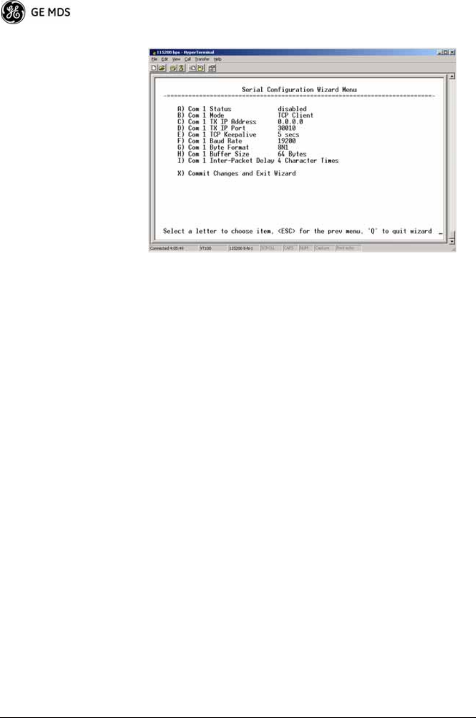
Configuring for TCP
Mode Invisible place holder
Figure 3-44. TCP Client Menu (Remote)
•Status—Enable/Disable the serial data port.
•Mode—TCP Client. This is the type of IP port offered by the
transceiver’s serial device server. [TCP, UDP; TCP]
•TX IP Address—The IP address to be used as a destination for
data received through the serial port.
[Any legal IP address; 0.0.0.0]
•TX IP Port—The destination IP port for data packets received
through the serial port on the transceiver.
[Any valid IP port; 30010]
•TCP Keepalive—Amount of time (in seconds) that the trans-
ceiver waits for data before terminating the TCP session.
[0—600; 600]
•Baud Rate—Data rate (payload) for the COM port, in
bits-per-second. [1,200—115,200; 19200]
•Byte Format—Interface signaling parameters. Data bits, parity
and stop bits.
[7N1, 7E1, 7O1, 8N1, 8E1, 8O1, 8N1, 7N2, 7E2, 7O2, 8N2, 8E2, 8O2;
8N1]
•Buffer Size—Maximum amount of characters that the Remote
end buffers locally before transmitting data through the serial
port. [1—255; 255]
•Inter-Frame Packet Delay—A measurement representing the
end of a message, measured in tenths of a second.
[default = 1 (that is, 1/10th of a second)]
•Commit Changes and Exit Wizard—Save and execute changes
made on this screen (shown only after changes have been
entered).
05-4446A01, Rev. D Mercury Reference Manual 81
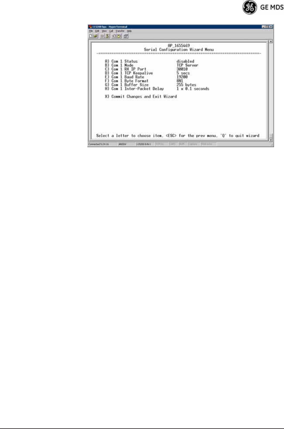
Invisible place holder
Figure 3-45. TCP Server Menu (AP)
•Status—Enable/Disable the serial data port.
•Mode—TCP Server. This is the type of IP port offered by the
transceiver’s serial device server.
[TCP, UDP; TCP]
•RX IP Port—Receive IP data from this source and pass it
through to the connected serial device. The application con-
necting to the local TCP or UDP socket must use this port
number.
[Any valid IP port; 30010]
•Baud Rate—Data rate (payload) for the COM port, in
bits-per-second. [1,200—115,200; 19200]
•Byte Format—Interface signaling parameters. Data bits, parity
and stop bits.
[7N1, 7E1, 7O1, 8N1, 8E1, 8O1, 8N1, 7N2, 7E2, 7O2, 8N2, 8E2, 8O2;
8N1]
•Buffer Size—Maximum amount of characters that the Remote
end buffers locally before transmitting data through the serial
port. [1—255; 255]
•Inter-Packet Delay—Amount of time that signal the end of a
message, measured in tenths of a second. [default = 1 (that is,
1/10th of a second)]
•Commit Changes and Exit Wizard—Save and execute changes
made on this screen (shown only after changes have been
entered).
IP-to-Serial Application Example
You must choose UDP or TCP to establish communications. This
depends on the type of device you are communicating with at the other
end of the IP network. In this example, we will use TCP to illustrate its
use.

82 Mercury Reference Manual 05-4446A01, Rev. D
In TCP mode, the transceiver remains in a passive mode, offering a
socket for connection. Once a request is received, data received at the
serial port is sent through the IP socket and vice versa, until the connec-
tion is closed or the link is interrupted. In this mode, the transceiver
behaves the same, whether it is an Access Point or a Remote.
(See Figure 3-46 and Table 3-4)
NOTE: The TCP session has a timeout of 10 minutes (600 seconds). If
inactive for that time, the session is closed. The transceiver
offers the port again for connection after this time expires.
Establishing a
Connection From the PC, establish a TCP connection to the IP address of the
Remote transceiver and to the IP port as configured above (30010). Use
a Telnet client application to establish this connection. Data can now be
sent between the PC and the RTU or other connected device.
Invisible place holder
Figure 3-46. IP-to-Serial Application Diagram
Point-to-Point Serial-to-Serial Application Example
Once you have configured the transceivers, they begin processing data
presented at the COM ports. Data presented at the Access Point’s COM
port is packetized and sent via UDP to the Remote. Upon receiving the
packet, the Remote strips the data out of the UDP packet and sends it out
its COM port. Likewise, data presented at the Remote’s COM port is
packetized, sent to the Access Point, stripped, and sent out the Access
Point’s COM port. This configuration does not use multicast addressing.
Ethernet
Crosssover
RTU
EIA-232
Computer
or Network
192.168.0.10 192.168.0.1 192.168.0.2
LA
NCOM
1COM
2PW
RLIN
K
Remote
Access Point
Table 3-4. Serial Port Application Configuration
IP-to-Serial Connection
Transceiver
Location
Menu Item Setting
Access Point None is required None is required
Remote Unit IP Address 192.168.0.2
Status Enabled
IP Protocol TCP
Baud Rate 9,600 (Example)
Flow Control None
Local IP Port 30010

05-4446A01, Rev. D Mercury Reference Manual 83
Invisible place holder
Figure 3-47. Point-to-Point Serial-to-Serial Application Diagram
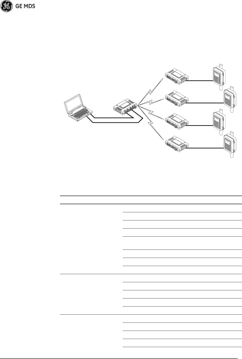
Point-to-Multipoint Serial-to-Serial Application Example
The operation and data flow for this mode is very similar to
Point-to-Point serial-to-serial application, except that it uses multicast
addressing. The primary difference is that data presented at the Access
Point’s COM port is packetized and sent using UDP to all of the
Remotes. Upon receiving the packet, all of the Remotes strip the data
from the UDP packet and send it out their COM ports. Likewise, data
presented at any of the Remotes’ COM ports is packetized, sent to the
Access Point, stripped, and sent out the Access Point’s COM port (see
Figure 3-48, Table 3-6, Figure 3-49, and Figure 3-50 on Page 85).
EIA-232
RTU
EIA-232
Terminal
or Computer
192.168.0.10 192.168.0.1 192.168.0.2
Remote
Access Point
LA
NCOM
1COM
2PW
RLIN
K
Table 3-5. Serial Port Application Configuration
Transceiver Location Menu Item Setting
Access Point (COM1) Status Enabled
Data Baud Rate 9,600 (Example)
SIFD 4
IP Protocol UDP
Remote IP
Address
192.168.0.2
(IP address of the Remote radio)
Remote IP Port 30010
Local IP Port 30010
Remote Unit (COM1) Status Enabled
Data Baud Rate 9,600 (Example)
Flow Control X-ON/X-OFF (Example)
SIFD 4 (Characters)
IP Protocol UDP
Remote IP
Address
192.168.0.1
(IP address of the AP)
Remote IP Port 30010
Local IP Port 30010

84 Mercury Reference Manual 05-4446A01, Rev. D
Invisible place holder
Figure 3-48. Point-to-Multipoint Serial-to-Serial Application
Diagram
Invisible place holder
192.168.0.3
192.168.0.4
EIA-232
Terminal
or Computer
RTU
RTU
RTU
EIA-232
EIA-232
EIA-232
192.168.0.10 192.168.0.1
192.168.0.2
Access Point
LA
NCOM
1COM
2PW
RLIN
K
Remote
LA
NCOM
1COM
2PW
RLIN
K
Remote
LA
NCOM
1COM
2PW
RLIN
K
Remote
Table 3-6. Serial Port Application Configuration
Transceiver Location Menu Item Setting
Access Point (COM1) Status Enabled
Baud Rate 9600 (Example)
Flow Control Disabled
IP Protocol UDP
Remote IP Address 224.254.1.1—
Multicast Address1
Remote IP Port 30010
Local IP Port 30010
Remote Units (COM1) Enable Enabled
Baud Rate 2,400 (Example)
Flow Control Hardware (Example)
IP Protocol UDP
Remote IP Address 192.168.0.1
Remote IP Port 30010
Local IP Port 30010
Local Multicast
Address
224.254.1.1 —
Multicast Address2
1. This address is an example only. Any Class D IP address
(224.0.0.0—239.255.255.255) will work.
05-4446A01, Rev. D Mercury Reference Manual 85
Figure 3-49. Serial Port ConfigurationAccess Point
Figure 3-50. Radio Serial Port ConfigurationRemote
Mixed Modes
In this example, the TCP mode does not involve the Access Point. Thus,
the transceiver in a single network can run in both modes at the same
time. In other words, you can configure some Remotes for TCP mode
and others (along with the Access Point) for UDP mode.
In this configuration, the Host PC can use both data paths to reach the
RTUs. This is helpful when a mixed collection of RTUs is present where
some RTUs can operate in a broadcast form while others cannot (see
Figure 3-51 on Page 86 and Table 3-7 on Page 86).
86 Mercury Reference Manual 05-4446A01, Rev. D
Operation and Data
Flow • Communicate with RTU A by Telneting to Remote 1, port 30010.
• Communicate with RTU B by Telneting to Remote 2, port 30010.
• Communicate with RTUs C and D by sending and receiving data
from the Access Point’s COM port.
• All communication paths can be used simultaneously.
Invisible place holder
Figure 3-51. Mixed-Modes Application Diagram
EIA-232
Terminal
or Computer
RTU–C
EIA-232
EIA-232
EIA-232
RTU–D
EIA-232
Ethernet
Crosssover
RTU–B
RTU–A
Access Point
Transceiver
LA
NCOM
1COM
2PW
RLIN
K
Remote 1
LA
NCOM
1COM
2PW
RLIN
K
Remote 2
LA
NCOM
1COM
2PW
RLIN
K
Remote 3
LA
NCOM
1COM
2PW
RLIN
K
Remote 4
Table 3-7. Serial Port Application Configuration
Transceiver Location Menu Item Setting
Access Point Status Enabled
Baud Rate 9,600
Flow Control Disabled
IP Protocol UDP
Send to Address A multicast IP address such as
224.254.1.1
Send to Port 30010
Receive on Port 30010
Receive on Address 0.0.0.0 (Not Used)
Remote Units 1 & 2 (COM1) Status Enabled
Baud Rate 2,400
Flow Control Disabled
IP Protocol TCP
Receive on Port 30010
Remote Units 3 & 4 (COM1) Status Enabled
Baud Rate 9,600
Flow Control Disabled
IP Protocol UDP

05-4446A01, Rev. D Mercury Reference Manual 87
3.6 MODBUS / TCP SERVER
CONFIGURATION
Modbus is a serial communications protocol developed by Schneider
Electric (Modicon) for communication between programmable logic
controllers (PLCs), remote terminal units (RTUs) and other industrial
electronic devices. It has become an established standard in the industry,
and is now used by many manufacturers of industrial data equipment.
Mercury Series transceivers running version 2.2.0 firmware or later
include Modbus functionality. This section of the addendum contains an
overview of the Modbus/TCP Server and provides menu details for
using this feature. You should also review Configuring for TCP Mode
section on Page 80.
NOTE: This material assumes you have an understanding of Ethernet
networking, TCP/IP, and Modbus serial protocols. Refer to the
following web site for additional information:
www.modicon.com/TECHPUBS/intr7.html.
NOTE: Modbus/TCP functionality is provided on the COM1 port of
the transceiver only.
3.6.1 Modbus/TCP in Mercury Transceivers—An
Overview
The transceiver implements a Modbus/TCP server that bridges
Modbus/TCP to either: Modbus RTU or Modbus/ASCII. It does not
function as a Modbus/TCP client.
The transceiver converts Modbus/TCP requests to either RTU or ASCII
serial Modbus packets and sends them to the configured serial port. It
waits up to the timeout period for a reply on the serial port, and if one
arrives, it converts the response back to Modbus/TCP and sends it to the
connected Modbus/TCP client.
Send to Address IP address of the AP
Send to Port 30010
Receive on Port 30010
Receive on Address 224.254.1.1
(The multicast IP address used
for the AP’s Send To Address
above)
Table 3-7. Serial Port Application Configuration (Continued)
Transceiver Location Menu Item Setting
88 Mercury Reference Manual 05-4446A01, Rev. D
3.6.2 Menu Selections
Connect a PC to the transceiver as described in STEP 3—CONNECT PC
TO THE TRANSCEIVER section on Page 25, and access the embedded
management system. Follow the steps below to proceed with
Modbus/TCP configuration.
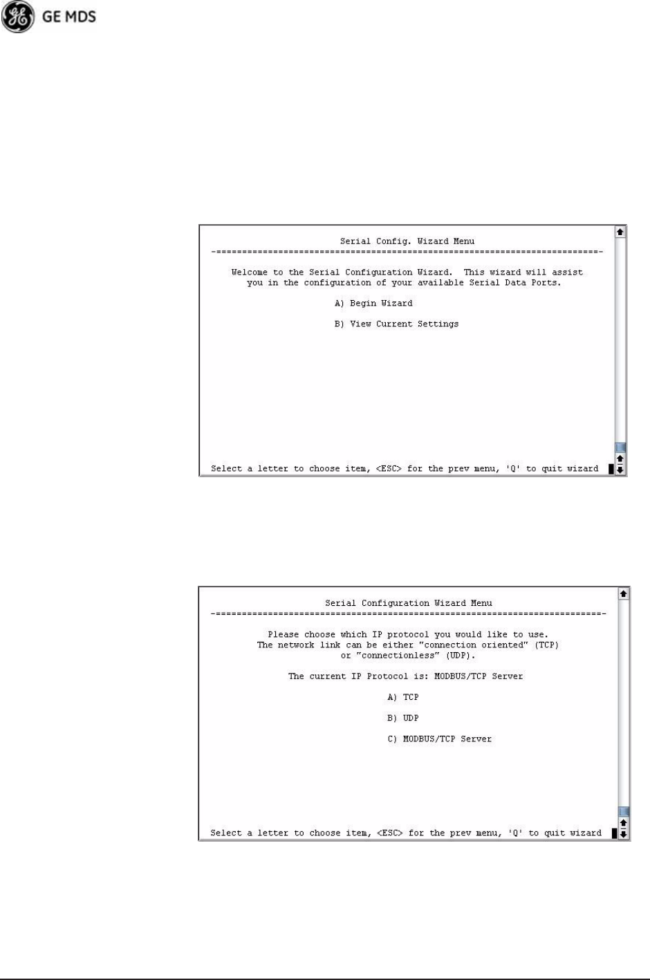
1. From the Serial Configuration Wizard opening screen (Figure 3-52
on Page 88), select A to begin the wizard.
Invisible place holder
Figure 3-52. Configuration Wizard Opening Screen
2. Choose the IP protocol you wish to use (TCP, UDP, or Mod-
bus/TCP) by selecting the appropriate letter from the menu.
Figure 3-53. IP Protocol Selection Screen
3. On the next screen (Figure 3-54 on Page 89), choose the listening
port you wish to use for the Modbus/TCP server. The default is port
502. Press N to continue.
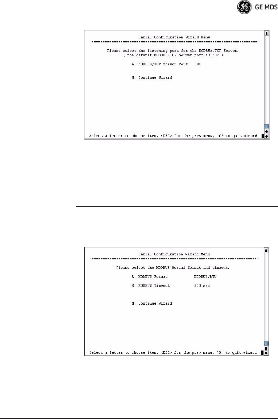
05-4446A01, Rev. D Mercury Reference Manual 89
Figure 3-54. Modbus/TCP Server Listening Port
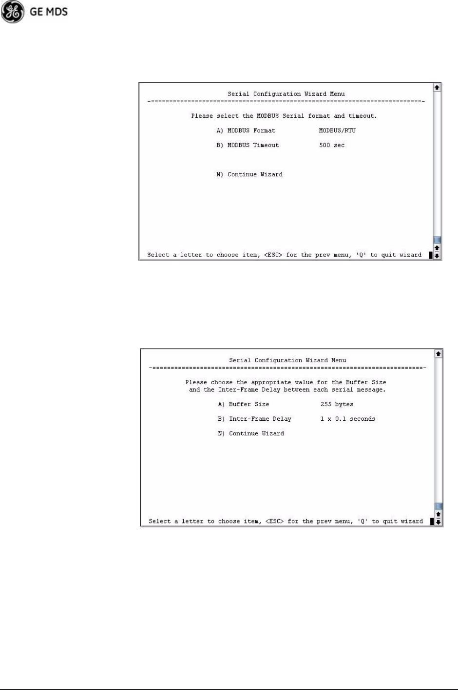
4. On the next screen (Figure 3-55), press A to change the Modbus
serial format, then press the space bar to toggle between the avail-
able formats (MODBUS/RTU or MODBUS/ASCII). Press B to enter the
Modbus serial timeout value in milliseconds. Press N to continue the
wizard.
NOTE: The only difference between Modbus/RTU and
Modbus/ASCII is the form of the framing sequence, error
check pattern, and address interpretation.
Figure 3-55. Choose Modbus Serial Format and Timeout Value
Note: Modbus Timeout setting is in milliseconds, not seconds
as displayed in the example above.
90 Mercury Reference Manual 05-4446A01, Rev. D
5. When the next screen appears (Figure 3-56), press A to select the
desired data baud rate and B to select the data byte format. Press N to
continue.
Figure 3-56. Select Data Baud Rate and Byte Format
6. The screen shown in Figure 3-57 appears next. Press A to select the
Buffer Size of message packets, and B to select the Inter-Frame
Delay. Press N to continue with the wizard.
Invisible place holder
Figure 3-57. Buffer Size and Inter-Frame Delay Values
7. On the next screen (Figure 3-58 on Page 91), select A and use the
spacebar to enable the serial port for data communication. Press N to
continue the wizard.
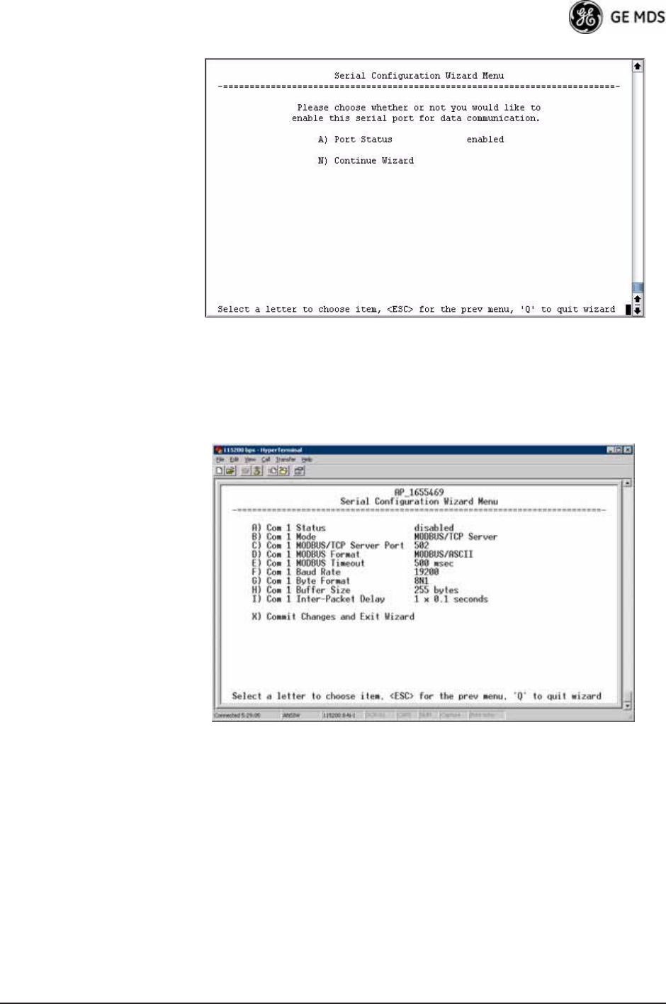
05-4446A01, Rev. D Mercury Reference Manual 91
Invisible place holder
Figure 3-58. Serial Port Status Screen
8. Review all settings on the summary screen shown in Figure 3-59. If
all settings are correct, press X to confirm and exit the wizard. If not,
select the letter of the item(s) you wish to change.
Invisible place holder
Figure 3-59. Serial ConfigurationSummary Screen
This completes the menu selections for Modbus/TCP operation.
3.7 SECURITY CONFIGURATION
MENU
The transceiver’s security features are grouped into four major catego-
ries and are accessible from the Security Configuration Menu (see
Figure 3-60). These categories are:
Device Security—Contains settings for controlling access to the radio
itself for configuration and management.
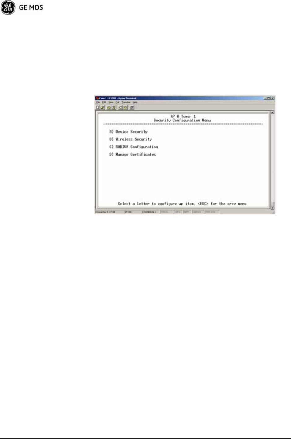
92 Mercury Reference Manual 05-4446A01, Rev. D
Wireless Security—Controls how and when radios communicate with
each other, as well as how data traffic is handled.
RADIUS Configuration—Deals with IEEE 802.1x device authentication
and authorization using a central server.
Manage Certificates (Remote only)—Allows setting of certificate types,
download paths, and TFTP parameters.
Invisible place holder
Figure 3-60. Security Configuration Menu
Selecting any of the Security Configuration Menu items opens a sub-
menu where you can view or change settings. Examples of these screens
and more detailed descriptions of their contents are provided below.
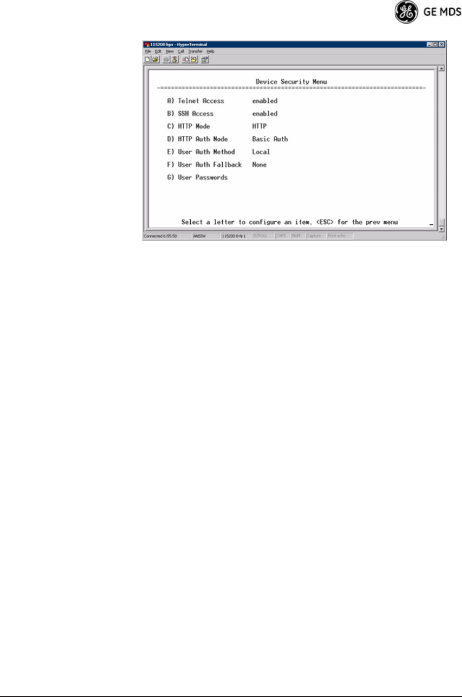
3.7.1 Device Security Menu
The Device Security Menu (Figure 3-61) controls how the radios can be
accessed either locally or remotely for configuration and management.
05-4446A01, Rev. D Mercury Reference Manual 93
Invisible place holder
Figure 3-61. Device Security Menu
•Telnet Access—Controls Telnet access to the transceiver’s man-
agement system. [enabled, disabled; enabled]
•SSH Access—Controls access to the Secure Shell (SSH) server.
[enabled, disabled; enabled]
•HTTP Mode—Controls access to the transceiver’s management
system via the web server. [disabled, HTTP, HTTPS; HTTP]
•HTTP Auth Mode—Selects the mode used for authenticating a web
user. [Basic Auth, MD5 Digest; Basic Auth]
•User Auth Method—View/set the method of authentication for
users. [Local, Radius; Local]
•User Auth Fallback—View/set method of authentication to use if
the RADIUS server is unavailable. [None, Local; None]
•User Passwords—Allows changing of Administrative and Guest
passwords. When selected, a new screen appears (Figure 3-62
on Page 94).
94 Mercury Reference Manual 05-4446A01, Rev. D
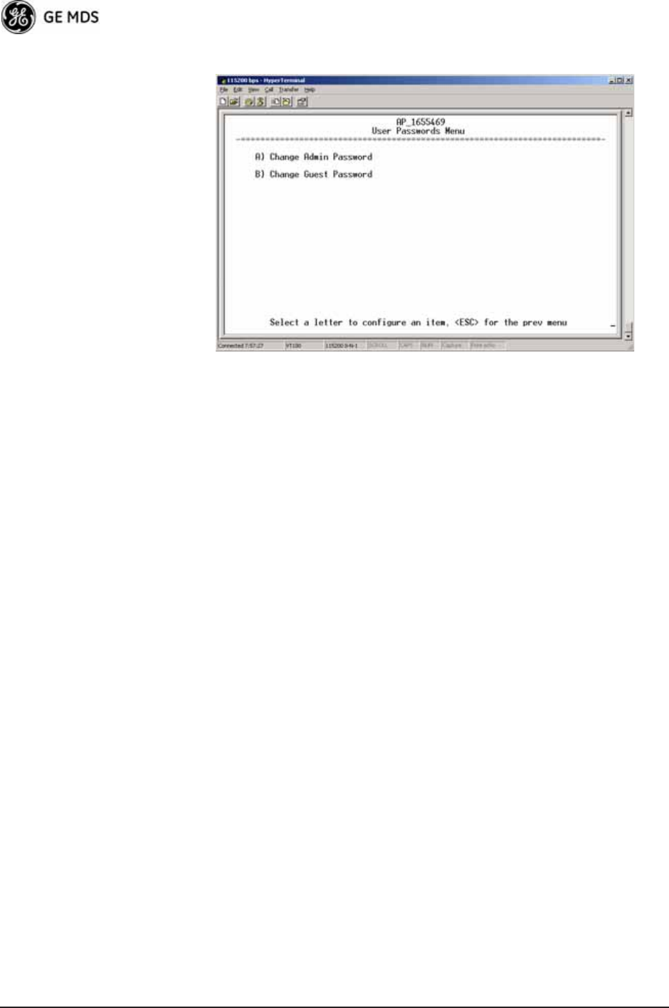
User Passwords Menu Invisible place holder
Figure 3-62. User Passwords Menu
To change the Administrator or Guest password, select the appropriate
menu item (A or B). A flashing cursor appears to the right. From here,
type the new password, which can be any alpha-numeric string up to 13
characters long. The change is asserted when you press the Return key.
•Change Admin Password—Allows you to set a new password.
[any alpha-numeric string up to 13 characters; admin]
•Change Guest Password—Allows you to set a new password.
[any alpha-numeric string up to 13 characters; guest]
TIP: For enhanced security, consider using misspelled words, a combi-
nation of letters and numbers, and a combination of upper and
lower case letters. Also, the more characters used (up to 13), the
more secure the password. These strategies help protect against
sophisticated hackers who use a database of common words (for
example, dictionary attacks) to determine a password.
3.7.2 Wireless Security Menu
The features in the Wireless Security menu (Figure 3-63 on Page 95)
control the communication of data across the wireless link. You can
authenticate the radios locally via a list of authorized radios, or remotely
via a centralized IEEE 802.1x device authentication server. This server
provides a centralized authentication mechanism based on standards.

05-4446A01, Rev. D Mercury Reference Manual 95
Invisible place holder
Figure 3-63. Wireless Security Menu
•Device Auth Mode—View/set the device’s authentication method.
[None, Local, IEEE 802.1X; None]
•Data Encryption—Controls the over-the-air payload data’s
AES-128 bit encryption. [enable, disable; disabled]
•Encryption Phrase—View/set the phrase used to generate encryp-
tion keys when encrypting over-the-air payload.
[any alpha-numeric string of 8 to 15 characters; <empty>]
•Max Remotes (AP only)—The maximum number of remotes an
AP can associate with.
•Approved Remotes (AP only)—Launches a submenu where you
can view, add, or delete approved Remotes. (See Figure 3-64.)
Approved Remotes
Submenu Setting the Device Auth Mode to Local forces an AP to check the Approved
Remotes List before establishing a radio link. A Remote must be in the
list before the AP associates and grants authorization. Before enabling
this option, at least one entry must already exist in the View Approved
Remotes list.

96 Mercury Reference Manual 05-4446A01, Rev. D
Invisible place holder
Figure 3-64. Approved Remotes Submenu
•Add Remote—Enter the MAC address of Remote.
[Any valid 6-digit hexadecimal MAC address; 00:00:00:00:00:00]
•Delete Remote—Enter the MAC address of Remote. For security
purposes, you should delete a stolen or deprovisioned radio
from this list.
•Add Associated Remotes—Add all currently associated remotes to
the approved remote list. Alternatively, you can enter each
Remote MAC manually.
•Delete All Remotes—Remove (complete purge) all Remotes from
current list.
•View Approved Remotes—Listing of approved Remotes by MAC
address. These radios are authorized to join this AP. If a Remote
is not in this list, it cannot associate with this AP.
3.7.3 IEEE 802.1x Device Authentication
This section covers the configuration needed for the radios to access the
IEEE 802.1x device authentication server, which provides Device Level
Security and for Wireless Access Security. GE MDS does not provide
the server software.
Operation of Device Authentication
Device authentication forces the radio to authenticate before allowing
user traffic to traverse the wireless network. When Device Security is
configured to use IEEE 802.1x as the Authentication Method, Remote
radios need three types of certificates: public (client), private, and root
(Certificate Authority). These files are unique to each Remote radio and
must first be created at the server and then installed into each unit via
TFTP. The certificate files must be in DER format.
Device authentication uses the serial number of each radio as the
Common Name (CN) in its certificate and in its RADIUS identity field.

05-4446A01, Rev. D Mercury Reference Manual 97
Each Access Point and Remote radio must be identified/recognized by
the device authentication server through the Common Name (Serial
number) and IP address entries.
NOTE: Consult your network administrator for assistance in configu-
ration, or for help with other issues that may arise.
To activate device authentication, select Device Auth Method and set
RADIUS as the active mode. The behavior of this setting differs
depending on whether it is implemented on an Access Point or a Remote
transceiver. An explanation of these behaviors is given below:
Access Point: When Device Auth Method is set to RADIUS, the AP disasso-
ciates all associated Remotes and waits for the device authentication
server to authenticate the Remotes before allowing data from them to
pass. When approval is received from the authentication server, data
from the Remote passes.
Remote: When Device Auth Method is set to RADIUS, the Remote halts any
data it is passing, and requests Authentication from the device authenti-
cation server. If accepted, data is transmitted.
Operation of User Authentication
User Authentication controls authentication of users who can manage
the device. This is in contrast to Device Authentication (above), which
authenticates devices that can participate in the data network. When user
authentication is set to Local or RADIUS, you must enter a valid user name
and password before you can manage the radio. In RADIUS mode, both
of these fields can be up to 40 characters long. In Local mode the user
name is admin and the password can be up to 13 characters long.
When set to RADIUS, all logins to the local configuration services must
be authenticated via the device authentication server, including Telnet
and SSH (Secure Shell) sessions. Authentication must be accepted
before access to the radio menu is granted.
98 Mercury Reference Manual 05-4446A01, Rev. D
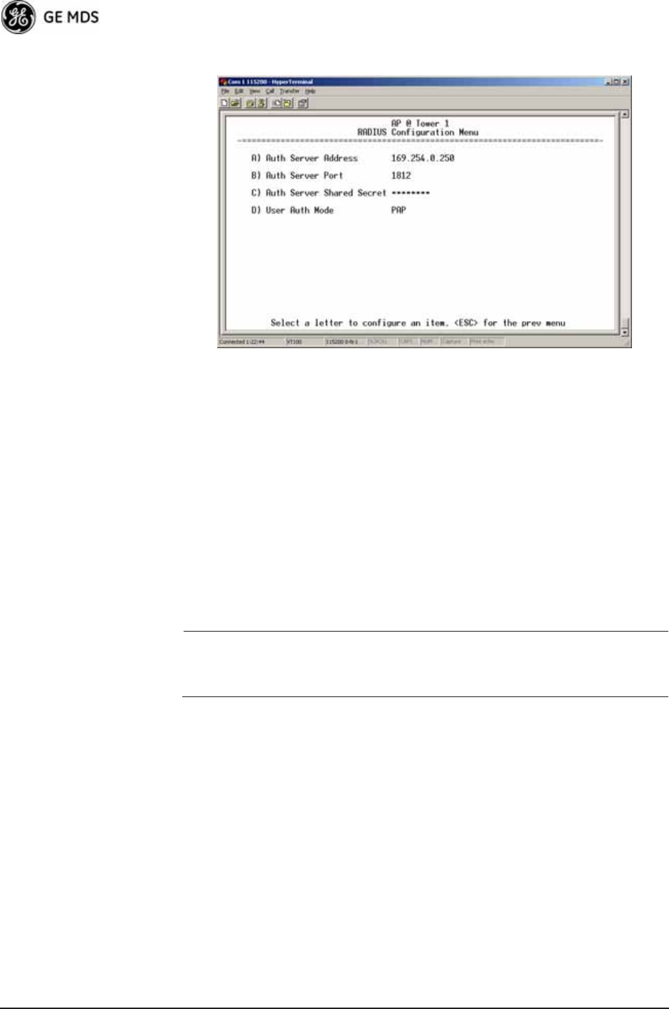
RADIUS Configuration Menu Invisible place holder
Figure 3-65. Radius Configuration Menu
•Auth Server Address—The IP address of the authentication
server. [any valid IP address; 0.0.0.0]
•Auth Server Port—The UDP Port of the authentication server.
[1812, 1645, 1812]
•Auth Server Shared Secret—User authentication and Device
authentication require a common shared secret to complete an
authentication transaction. This entry must match the string
used to configure the appropriate files on the authentication
server.
[<empty>; any alpha-numeric string up to 16 characters]
•User Auth Mode—RADIUS Authentication algorithm.
[PAP, CHAP, EAP; PAP]
NOTE: CHAP is a more secure algorithm than PAP. PAP may display
the login password in log files at the authentication server
while CHAP will encrypt this information.
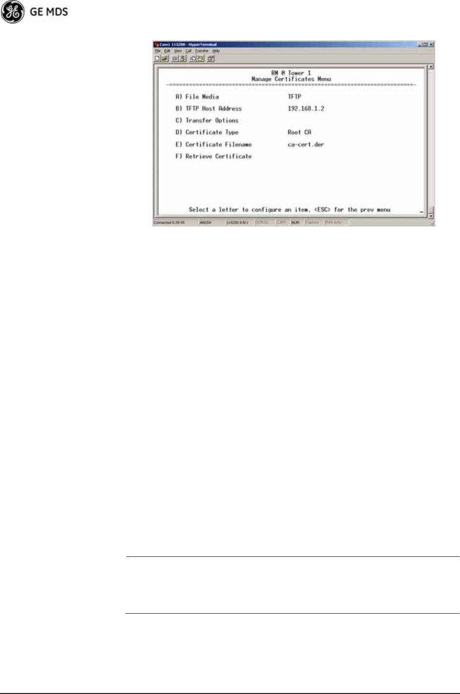
3.7.4 Manage Certificates
Use Certificate generation software to generate certificate files, then
install these files into each Remote unit using TFTP. This is done using
the Manage Certificates Menu (Figure 3-66 on Page 99).
The certificate files must be in DER format. The Common Name (CN)
field in the public certificate file must match the serial number of the
unit it is installed on.
05-4446A01, Rev. D Mercury Reference Manual 99
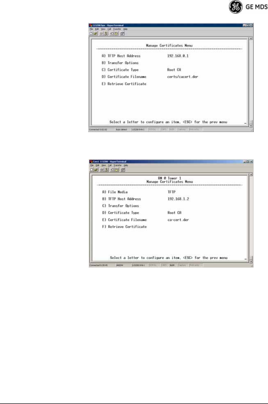
Invisible place holder
Figure 3-66. Manage Certificates Menu
Invisible place holder
Figure 3-67. Manage Certificates Menu, TFTP Mode
(Firmware version 3.0 Remotes)
100 Mercury Reference Manual 05-4446A01, Rev. D
Invisible place holder
Figure 3-68. Manage Certificates Menu, USB Mode
(Firmware version 3.0 Remotes)
•File Media—A selection of methods for transferring files to and
from the radio. On firmware version 3.0 radios, the options are
TFTP and USB.
•TFTP Host Address—(Telnet/Terminal only)—IP address of the com-
puter on which the TFTP server resides. This same IP address is
used in other screens/functions (reprogramming, logging, etc.).
Changing it here also changes it for other screens/functions.
[Any valid IP address; 127.0.0.1].
•Transfer Options—A menu for configuring the TFTP transfer.
(See Figure 3-69 on Page 101.)
Three certificate files (Root CA, Client, and Private Key) must be
present in each of the Remote radios. Use the commands described
below to install these files into each Remote radio:
•Certificate Type—Selects one of the three certificate file types
mentioned above. [Root CA, Client, Private Key; Root CA]
•Certificate Filename—Specifies the software path and filename
for downloading certificates.
•Retrieve Certificate—Initiates the retrieval of the certificate file
from the storage location. A successful installation issues a Com-
plete status message.
NOTE: It is imperative that the three certificate files are installed
correctly into the Remote radio, in their respective file types.
If they are not, the Remote is un-authenticated for data traffic.
Consult your network administrator for more information.

05-4446A01, Rev. D Mercury Reference Manual 101
Invisible place holder
Figure 3-69. Transfer Options Menu
•TFTP Timeout—The time the client radio will wait for a response
from the server before ending the transfer.
•TFTP Block Size—The amount of data sent in each TFTP packet.
3.8 REDUNDANCY CONFIGURATION
(AP ONLY)
For operation in protected (redundant) mode, an AP must be in a Pack-
aged P23 enclosure with a backup radio. See MDS publication
05-4161A01 for details. This manual is available under the Downloads
tab at www.GEmds.com.
The Redundancy Configuration Menu (Figure 3-70) is where you
enable/disable redundancy operation and define the triggers that will
cause a switchover.

102 Mercury Reference Manual 05-4446A01, Rev. D
Invisible place holder
Figure 3-70. Redundancy Configuration Menu (AP Only)
•Redundancy Configuration—Enable/disable redundancy switcho-
ver for AP. [enabled, disabled; disabled]
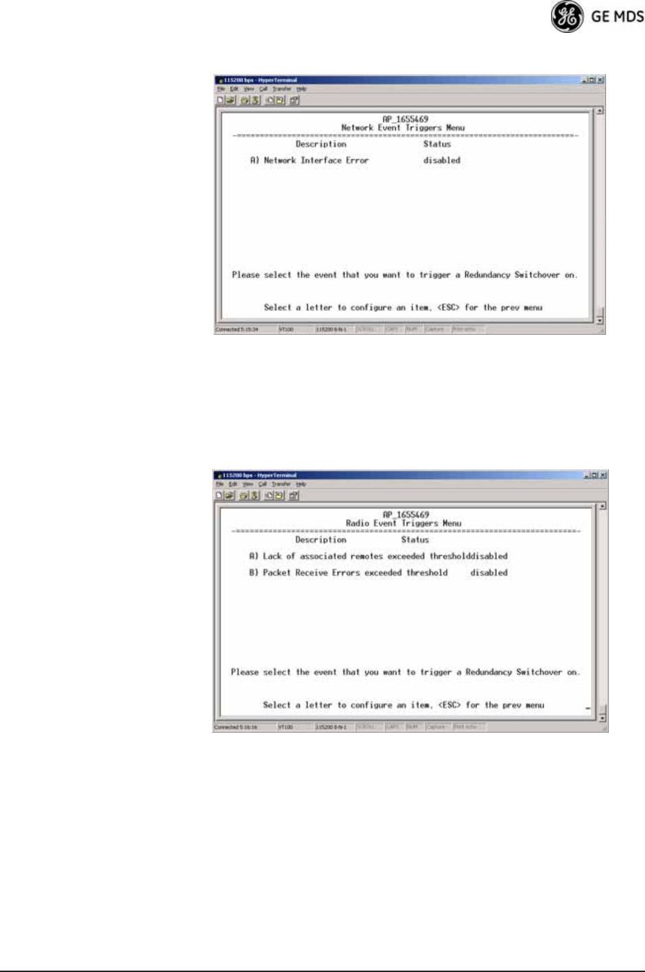
•Network Event Triggers—This selection opens a submenu
(Figure 3-71 on Page 103) where you can set/view the trigger
status for Network Events.
•Radio Event Triggers—This selection opens a submenu
(Figure 3-72 on Page 103) where you can set/view the trigger
status for Radio Events, such as a loss of associated Remotes or
excessive packet errors.
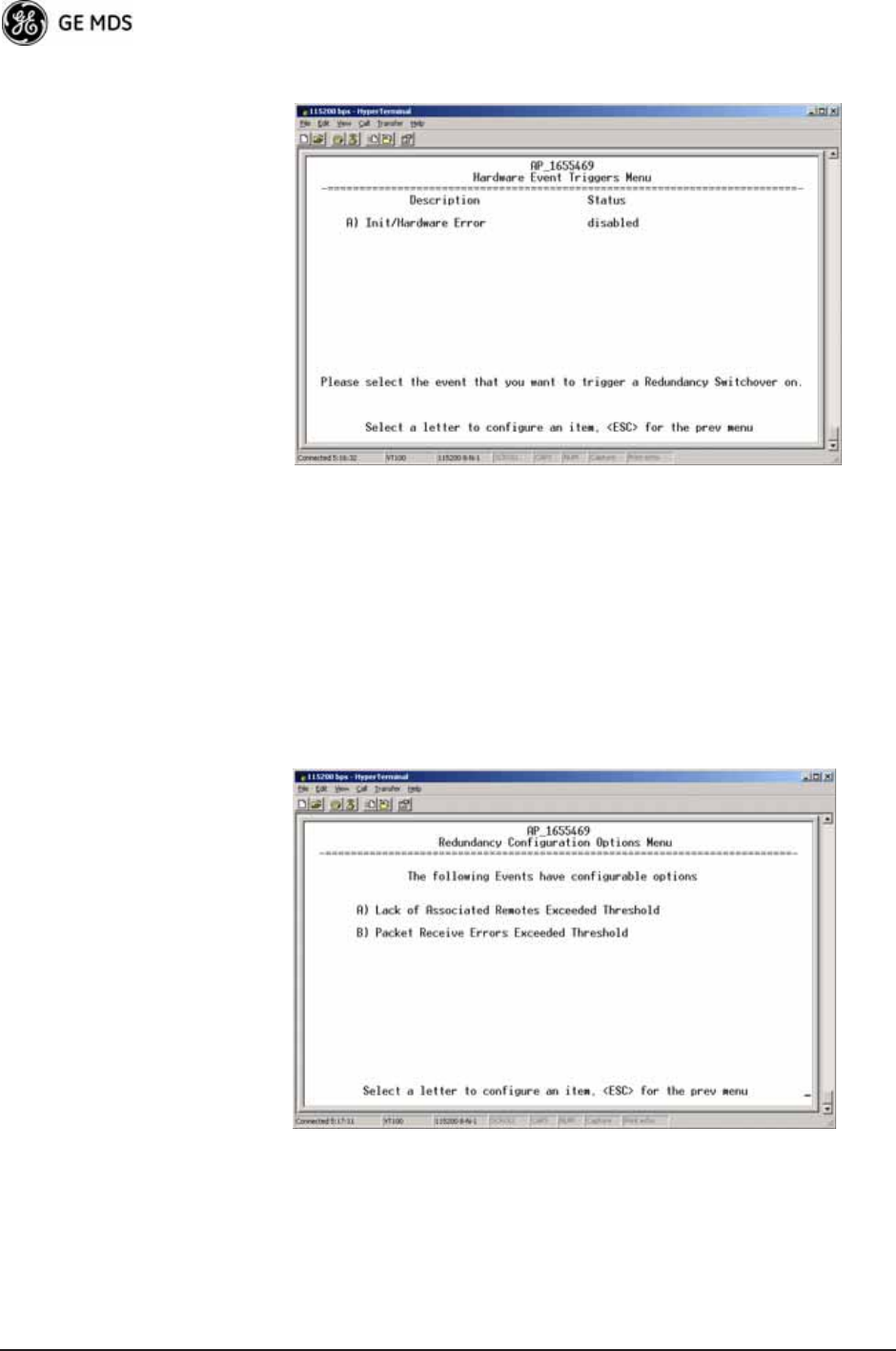
•Hardware Event Triggers—This selection opens a submenu
(Figure 3-73 on Page 104) where you can set/view the trigger
status for initialization/hardware errors.
•Redundancy Configuration Options—This selection opens a sub-
menu (Figure 3-74 on Page 104) where you can set the thresh-
old criteria for declaring an error event.
•Force Switchover—Selecting this option forces a manual (user
initiated) switchover to the backup AP. The “challenge ques-
tion” Are you sure? (y/n) is presented to avoid an unintended
switchover. To invoke the change, press the letter y followed by
the Enter key.
05-4446A01, Rev. D Mercury Reference Manual 103
Network Event Triggers Menu Invisible place holder
Figure 3-71. Network Events Triggers Menu
•Network Interface Error—This setting determines whether or not a
network interface error will cause redundancy switchover.
[enabled, disabled; disabled]
Radio Event Triggers Invisible place holder
Figure 3-72. Radio Event Triggers
•Lack of associated remotes exceeded threshold—This setting deter-
mines whether or not a switchover occurs when a lack of asso-
ciated Remote units exceeds the time period set in Figure 3-75
on Page 105. [enabled, disabled; disabled]
•Packet Receive Errors exceeded threshold—This setting determines
whether or not a switchover occurs when the number of Packet
Receive errors exceeds the number set in Figure 3-76 on
Page 105. [enabled, disabled; disabled]
104 Mercury Reference Manual 05-4446A01, Rev. D
Hardware Event Triggers Invisible place holder
Figure 3-73. Hardware Event Triggers
•Init/Hardware Error—This setting determines whether or not an
initialization or hardware error results in a redundancy switcho-
ver. [enabled, disabled; disabled]
Redundancy Configuration Options Menu
Use this menu (Figure 3-74) to set the thresholds for the Lack of Asso-
ciated Remotes and Packet Receive Errors. Selecting either item opens
a submenu where you can view or change settings.
Invisible place holder
Figure 3-74. Redundancy Configuration Options Menu
•Lack of Associated Remotes Exceeded Threshold—This selection
opens a submenu (Figure 3-75) where you can view or change
the time period allowed for a lack of associated Remotes.
05-4446A01, Rev. D Mercury Reference Manual 105
•Packet Receive Errors Exceeded Threshold—This selection opens a
submenu (Figure 3-76 on Page 105) where you can view or
change the maximum allowable number of receive errors.
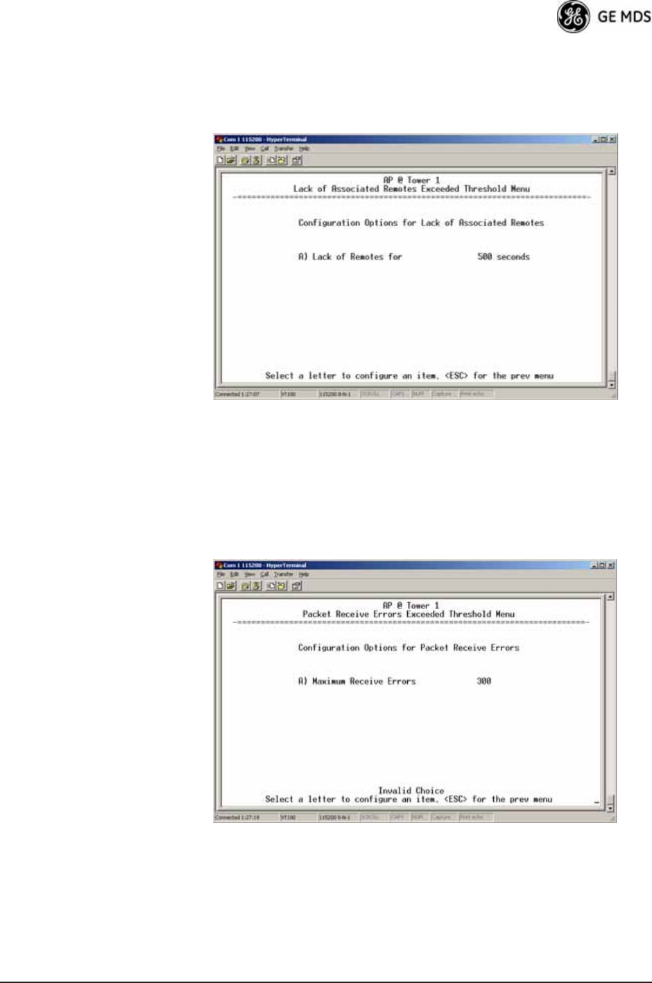
Lack of Associated
Remotes Exceeded
Threshold Menu
Invisible place holder
Figure 3-75. Lack of Associated Remotes
Exceeded Threshold Menu
•Lack of Remotes for—Select this item to change the time setting
(in seconds) for a lack of associated Remotes. When there are
no associated Remotes for a period exceeding this time, a redun-
dancy switchover occurs. [60-500; 500]
Packet Receive
Errors Exceeded
Threshold Menu
Invisible place holder
Figure 3-76. Packet Receive Errors Exceeded Threshold Menu
•Maximum Receive Errors—Select this item to change the maxi-
mum allowable number of receive errors. When the number of
errors exceeds this number, a redundancy switchover occurs.
[0-1000; 500]
106 Mercury Reference Manual 05-4446A01, Rev. D
3.9 GPS CONFIGURATION (REMOTE
ONLY)
This menu allows you to view or set important parameters for the
built-in Global Positioning System (GPS) receiver in the Mercury
Remote. Mercury 3650 Remote units do not have or require GPS func-
tionality. Details about the NMEA sentences generated by the GE MDS
Mercury can be found at http://www.nps.gov/gis/gps/NMEA_sentences.html.
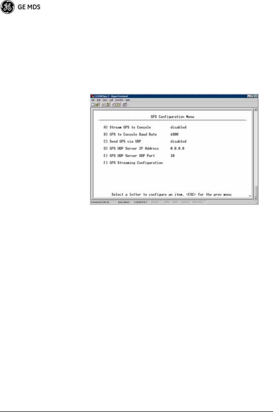
Invisible place holder
Figure 3-77. GPS Configuration Menu (Remote Only)
•Stream GPS to Console—Used to enable/disable streaming of
GPS NMEA data to the console port (COM1). Baud rate is 4800
baud when Stream GPS to console is enabled.
[enabled, disabled; disabled]
•GPS to Console Baud Rate—The serial baud rate when GPS
streaming is enabled.
•Send GPS via UDP—Used to enable/disable sending GPS NMEA
data to a server via UDP. [enabled, disabled; disabled]
•GPS UDP Server IP Address—Specify the destination address for
GPS NMEA UDP packets. [any valid IP address; 0.0.0.0]
•GPS UDP Server UDP Port—Destination UDP port for GPS
NMEA UDP packets. [valid UDP port number; 0]
•GPS Streaming Configuration—A submenu for setting GPS
NMEA outputs. (See Figure 3-78 on Page 107.)
05-4446A01, Rev. D Mercury Reference Manual 107
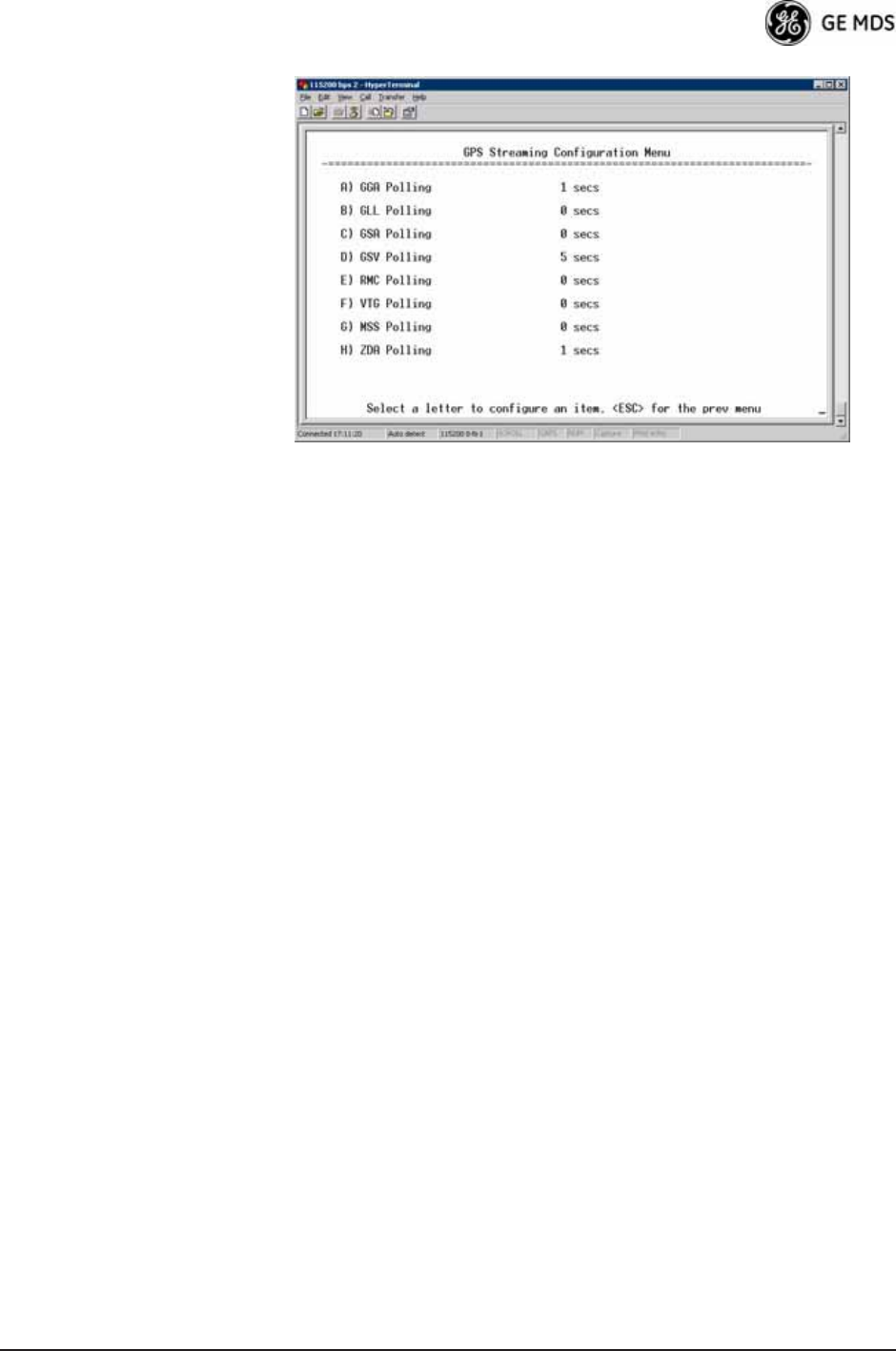
Invisible place holder
Figure 3-78. GPS Streaming Configuration Menu
•GGA Polling—Seconds between GGA string outputs, the satellite
fix information.
•GLL Polling—Seconds between GLL string outputs, the latitude
and longitude information.
•GSA Polling—Seconds between GSA string outputs, the overall
satellite data.
•GSV Polling—Seconds between GSV string outputs, the detailed
satellite data.
•RMC Polling—Seconds between RMC string outputs, the recom-
mended minimum data.
•VTG Polling—Seconds between VTG string outputs, the vector
track and speed over ground.
•MSS Polling—Seconds between MSS string outputs, the beacon
receiver status information.
•ZDA Polling—Seconds between ZDA string outputs, data, and
time.
108 Mercury Reference Manual 05-4446A01, Rev. D
3.10 DEVICE INFORMATION MENU
Figure 3-79 shows the menu that displays basic administrative data on
the unit to which you are connected. It also provides access to user-spe-
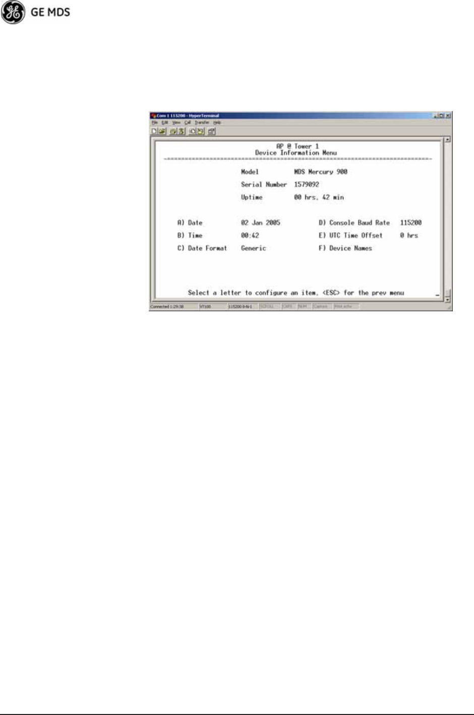
cific parameters such as date/time settings and device names.
Figure 3-79. Device Information Menu
•Model (Display only)
•Serial Number (Display only)
•Uptime (Display only)—Elapsed time since boot-up.
•Date—Current date being used for the transceiver logs. User-set-
able. (Value lost with power failure if SNTP [Simple Network
Time Protocol] server not accessible.)
•Time—Current time of day. User-setable.
Setting: HH:MM:SS
(Value lost with power failure if SNTP server not accessible.)
•Date Format—Select presentation format:
• Generic = dd Mmm yyyy
• European = dd-mm-yyyy
• US = mm-dd-yyyy
•Console Baud Rate—Used to set/display data communications
rate (in bits-per-second) between a connected console terminal
and the radio. [115200]
05-4446A01, Rev. D Mercury Reference Manual 109
•UTC Time Offset—Set/view the number of hours difference
between your local clock time and Universal Coordinated Time.
Offsets for U.S. times zones are shown in the chart below.
•Device Names—Fields used at user’s discretion for general
administrative purposes. The Device Name field is shown on all
menu screen headings. (See Figure 3-80 on Page 109)
NOTE: The transceivers do not save time and date information when
power is removed.
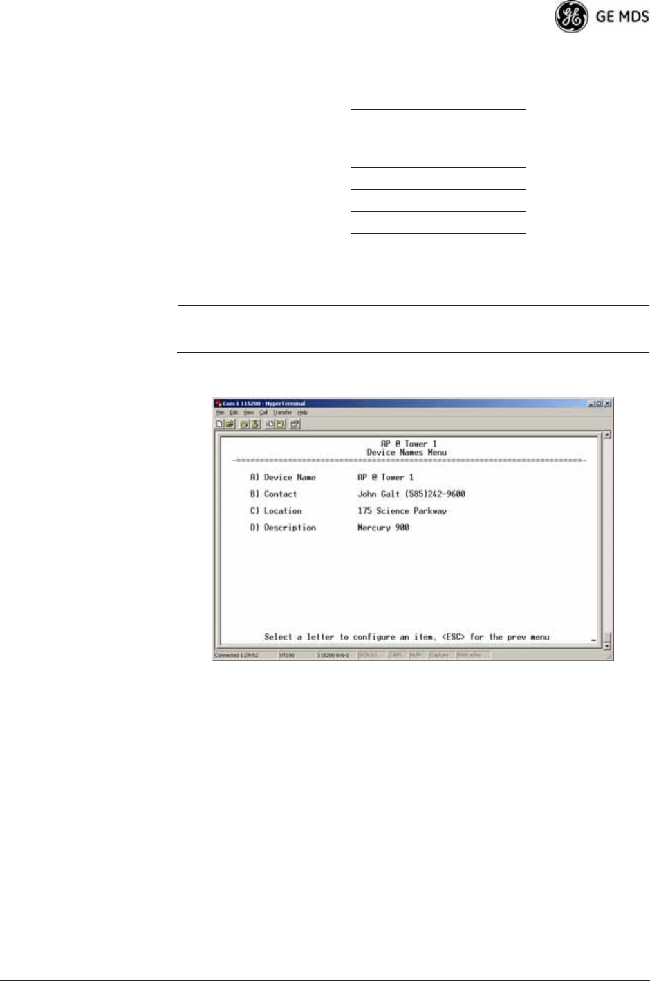
Device Names Menu
Figure 3-80. Device Names Menu
•Device Name—Used by the transceiver as the “Realm” name
for network login (web browser only) and menu headings.
•Contact—User defined; appears on this screen only.
•Location—User defined; appears on this screen only.
•Description—User defined; appears on this screen only.
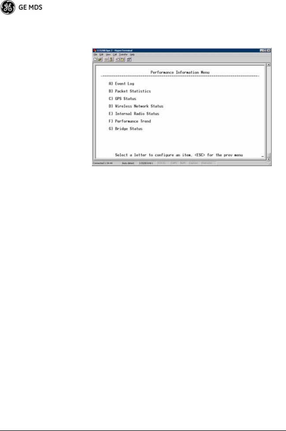
3.11 PERFORMANCE INFORMATION
MENU
The Performance Information Menu (Figure 3-81 on Page 110) is the
entry point for a series of submenus where you can evaluate transceiver
operating status and network performance. You can use this menu as an
Time Zone
(U.S.)
UTC Offset
(Hours)
PST -8
MST -7
CST -6
EST -5
110 Mercury Reference Manual 05-4446A01, Rev. D
important troubleshooting tool, or for evaluating changes made to the
network configuration or equipment.
Invisible place holder
Figure 3-81. Performance Information Menu
•Event Log—Access this menu for managing the unit’s opera-
tional activities log. (See Figure 3-84 on Page 112 for details.)
•Packet Statistics—Multiple radio and network operating statis-
tics. (See Figure 3-86 on Page 114 for details.)
•GPS Status—Shows satellite fix status, number of satellites
being received, and unit location data. (See Figure 3-87 on
Page 115 for details.)
•Wireless Network Status—Current AP association state and MAC
address. (See Figure 3-89 on Page 117 for details.)
•Internal Radio Status (Remote Only)—Shows connection status,
RF parameters, and total FEC count for the unit. (See
Figure 3-94 on Page 119 for details.)
•Performance Trend (Remote Only)—Launches a continuously
updated list of performance parameters (RSSI, Signal-to-Noise
Ratio, Transmit Power, Latitude, Longitude, Connection Status,
and FEC Blocks). (See Figure 3-82 on Page 111.)
•Bridge Status—Displays the network bridge status. (See
Figure 3-83 on Page 111.)
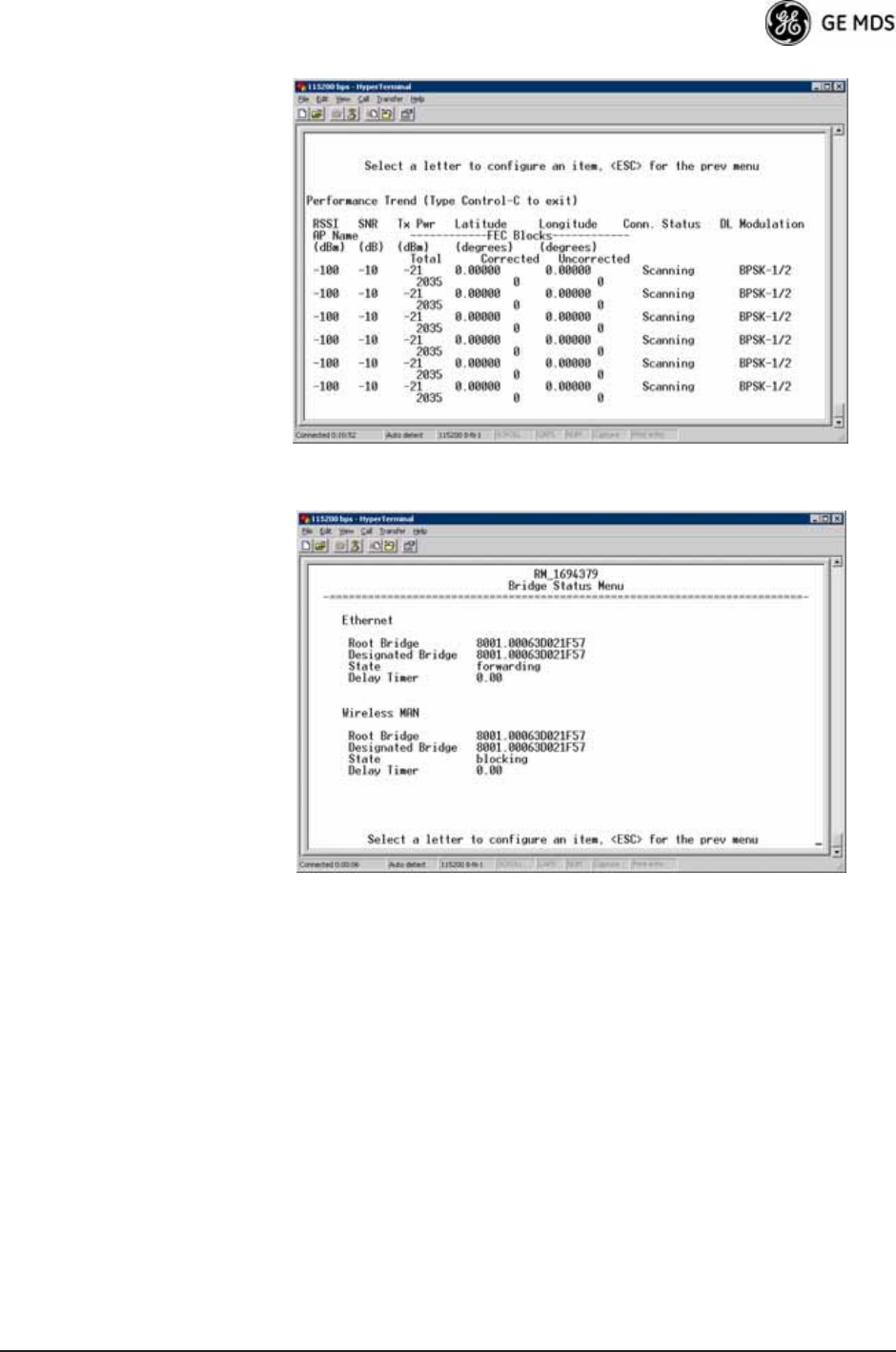
05-4446A01, Rev. D Mercury Reference Manual 111
Invisible place holder
Figure 3-82. Performance Trend Screen
Invisible place holder
Figure 3-83. Bridge Status Menu
112 Mercury Reference Manual 05-4446A01, Rev. D
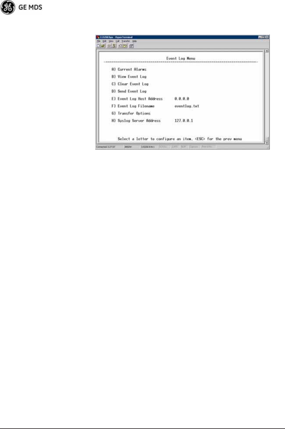
Event Log Menu Invisible place holder
Figure 3-84. Event Log Menu
•Current Alarms—Shows active alarms (if any) reported by the
transceiver.
•View Event Log—Displays a log of radio events arranged by event
number, date, and time. (Example shown in Figure 3-85 on
Page 113).
•Clear Event Log—Erases all previously logged events.
•Send Event Log—Sends the event log to the server. You must
answer the challenge question Send File? y/n before the request
proceeds.
•Event Log Host Address—Set/display the IP address of the TFTP
server. [any valid IP address; 0.0.0.0]
•Event Log Filename—Set/display the name of the event log file on
the TFTP server. [any valid filename; eventlog.txt]
•Transfer Options—A menu for configuring the TFTP transfer.
•Syslog Server Address—Use this selection to set or view the IP
address of the Syslog server. Syslog is a standardized protocol
for sending IP log data across a network. Low cost (or even free)
Syslog downloads are available online by searching for the term
“Syslog Server.” [any valid IP address; 0.0.0.0]

05-4446A01, Rev. D Mercury Reference Manual 113
View Event Log
Menu Invisible place holder
Figure 3-85. View Event Log Menu
The transceiver’s microprocessor monitors many operational parame-
ters and logs them. Events are classified into four levels of importance,
which are described in Table 3-8. Some of these events result from a
condition that prevents normal operation of the unit. These are “critical”
events that cause the unit to enter an “alarmed” state and the PWR LED
to blink until the condition is corrected. All events are stored in the
Event Log..
Time and Date The events stored in the Event Log are time-stamped using the time and
date of the locally connected device. The Access Point obtains the time
and date from a Time Server. This server is typically a standard Win-
dows PC server SNTP application. In the absence of the SNTP services,
the user must manually enter time and date information at the Access
Point. (See “DEVICE INFORMATION MENU” on Page 108 for SNTP
server identification.) The manually set time and date clock relies on the
unit’s primary power. A loss of power resets the clock to 02 Jan 2005 but
does not affect previously stored error events.
Packet Statistics Menu
The transceivers maintain running counters of different categories of
events in the Ethernet protocol. The Packet Statistics refer to each
Ethernet interface from the perspective of the radio.
Table 3-8. Event Classifications
Level Description/Impact
Informational Normal operating activities
Minor Does not affect unit operation
Major Degraded unit performance but
still capable of operation
Critical Prevents the unit from operating

114 Mercury Reference Manual 05-4446A01, Rev. D
Invisible place holder
Figure 3-86. Packet Statistics Menu
•Packets Received—Data packets received by this unit.
•Packets Sent—Data packets sent by this unit.
•Bytes Received—Data bytes received by this unit.
•Bytes Sent—Data bytes sent by this unit.
•Packets Dropped—To-be-transmitted packets dropped because
of a lack of buffers in the outbound queue.
•Receive Errors—Packets that do not pass CRC. This may be due
to transmissions corrupted by RF interference, Ethernet colli-
sions, or degradation. If significant Ethernet Receive Errors are
observed, check the quality of your Ethernet cabling and con-
nectors, or that you do not have cable lengths exceeding the
specification limits.
•Lost Carrier Detected—This parameter reports how many times
the wired Ethernet connection has lost link.
•Clear Ethernet Statistics—Resets the statistics counter. You must
answer the challenge question Send File? y/n before the request
proceeds.
•Clear MDS Wireless Statistics—Resets the statistics counter. You
must answer the challenge question Send File? y/n before the
request proceeds.
05-4446A01, Rev. D Mercury Reference Manual 115
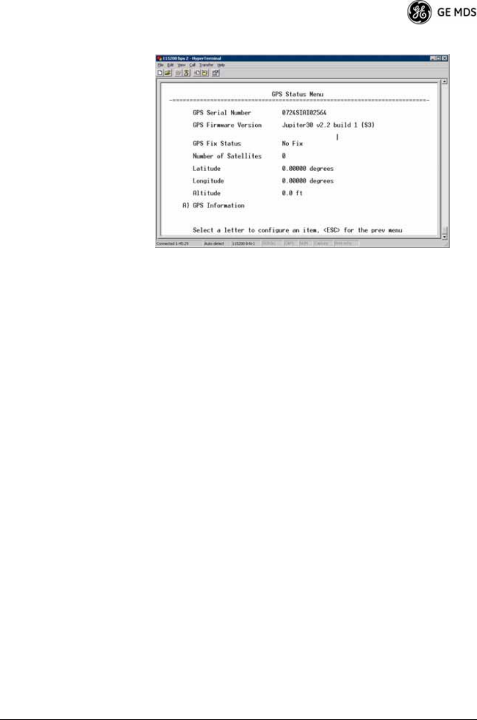
GPS Status Menu Invisible place holder
Figure 3-87. GPS Status Menu
•GPS Serial Number—The serial number of the GPS unit in the
radio.
•GPS Firmware Version—The firmware version running on the
GPS chip.
•Satellite Fix Status—Indicates whether or not the unit has
achieved signal lock with the minimum required number of
GPS satellites. The transceiver requires a fix on five satellites to
achieve Precise Positioning Service (PPS) and four to maintain
PPS. [No Fix, Fix]
•Number of Satellites—Shows the number of GPS satellites
received by the transceiver. Although there are typically 24
active GPS satellites orbiting the Earth twice a day, only a sub-
set of these is “visible” to a receiver at a given location. A good
signal provides information from six to ten satellites.
•Latitude—Shows the transceiver’s latitudinal location (in
degrees), based on GPS data received from the satellites.
•Longitude—Shows the transceiver’s longitudinal location (in
degrees), based on GPS data received from the satellites.
•Altitude—Shows the transceiver’s altitude above sea level (in
feet), based on GPS data received from the satellites.
•GPS Information—Shows data about the individual satellites
being received, including the Pseudo-Random Noise (PRN)
code (a unique bit stream for each satellite), the satellite’s ele-
vation (in degrees), azimuth (in degrees), and the sig-
nal-to-noise ratio of the carrier signal (SNR). Figure 3-88 on
Page 116 shows a layout example for this screen.

116 Mercury Reference Manual 05-4446A01, Rev. D
GPS Information
Menu Invisible place holder
Figure 3-88. GPS Information Menu
Wireless Network Status Menu
The Wireless Network Status screen provides information on a key
operating process of the transceiver—the association of the Remote with
the Access Point. The following is a description of how this process
takes place and is monitored by the menu system.
The Transceivers
Association Process If the Access Point and Remote are configured for single channel oper-
ation, the Remote monitors the channel for Access Point transmissions.
The Remote synchronizes its power, timing, and frequency to the
Access Point, then requests access to the network. The Access Point and
Remote check each other’s authorization and authentication according
to the configuration of the Device Authorization and Encryption Enable
parameters, and the Network Name parameter. The Remote is then associ-
ated.
If the Access Point and Remote are configured for frequency hopping,
the Remote hops with the Access Point according to Access Point’s con-
figuration. Once the Remote is hopping in sync with the Access Point,
the rest of the association process is the same as for single channel oper-
ation.
05-4446A01, Rev. D Mercury Reference Manual 117
Invisible place holder
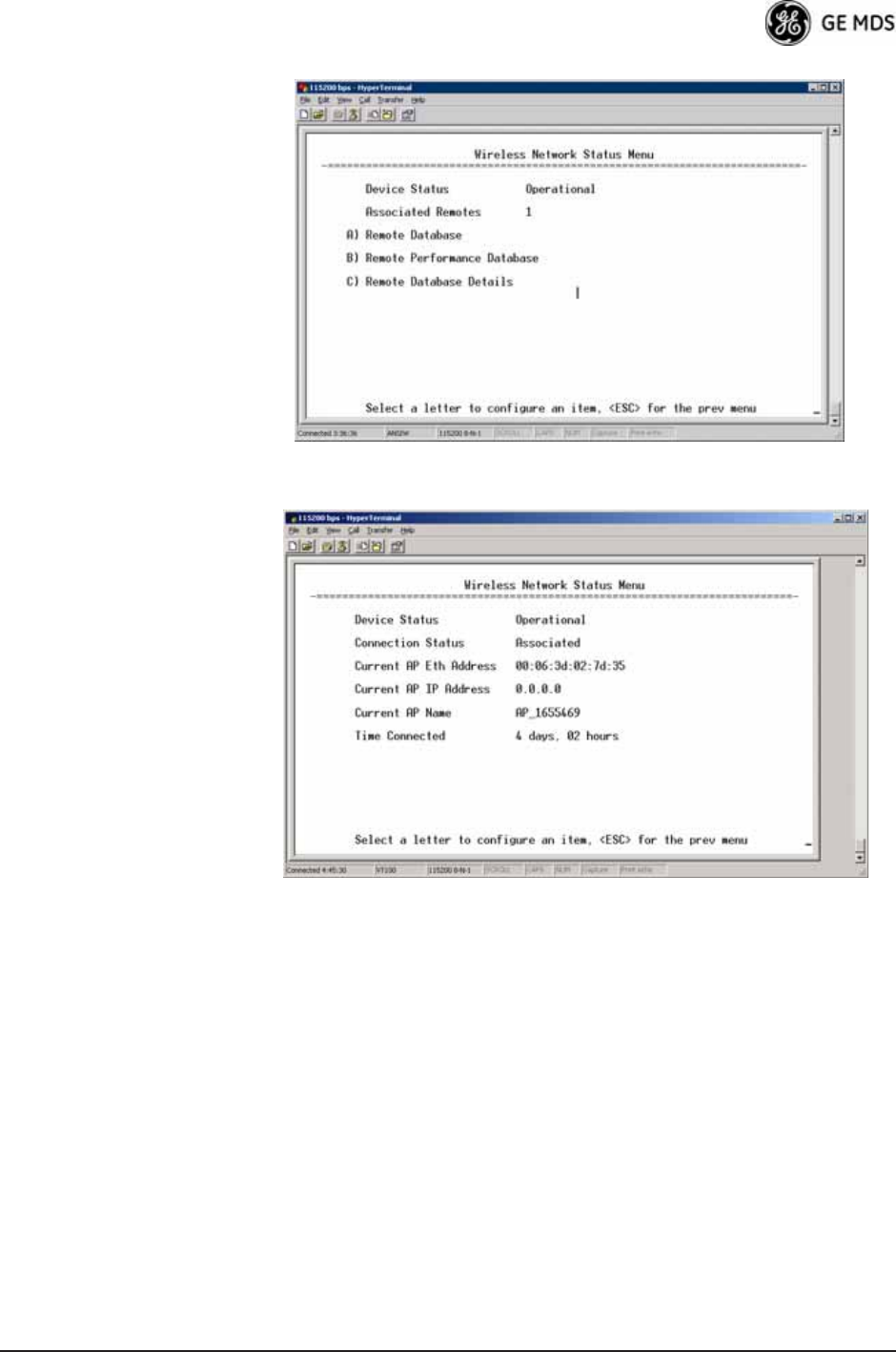
Figure 3-89. Wireless Network Status Menu (AP)
Invisible place holder
Figure 3-90. Wireless Network Status Menu (Remote)
•Device Status—Displays the overall operating condition of the
transceiver. [Operational, Alarmed]
•Associated Remotes (AP Only)—Shows the number of Remote
transceivers currently associated with the AP.
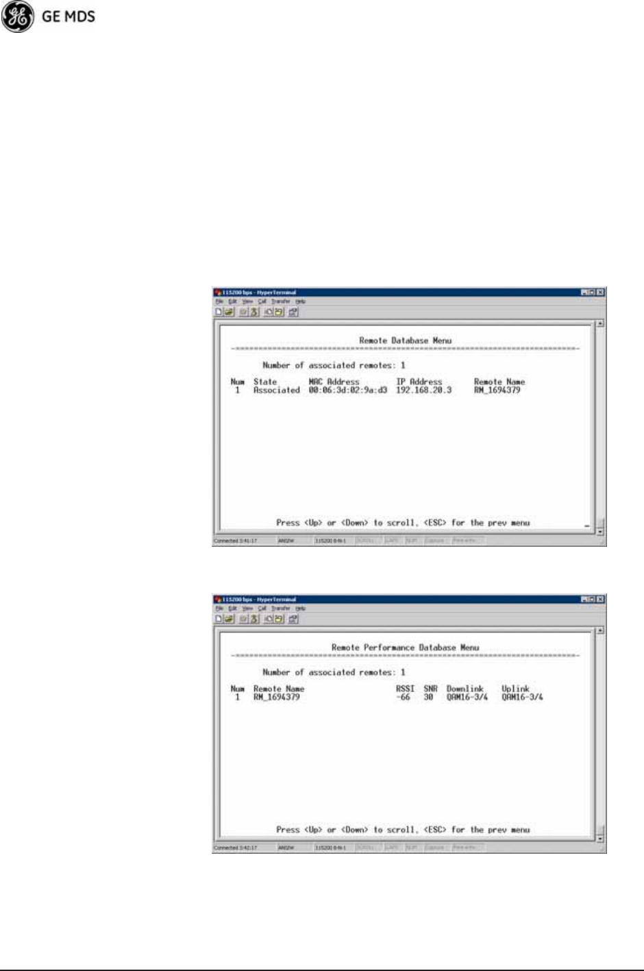
•Remote Database (AP Only)—Displays a submenu where associ-
ated Remotes are listed in table form according to their number,
operational state, MAC address, IP address, and name (if
assigned). (See Figure 3-91 on Page 118.)
•Remote Performance Database (AP Only)—Displays a submenu
where associated Remote performance data is listed in table
form. Remotes are presented according to their number, MAC
address, RSSI, SNR, modulation type, and FEC total. (See
Figure 3-92 on Page 118.)
118 Mercury Reference Manual 05-4446A01, Rev. D
•Connection Status (Remote Only)—Displays the current state of
the wireless network communication as follows: Scanning, Rang-
ing, Connecting, Authenticating, Associated, or Alarmed. A complete
explanation of these operating states is provided in Table 4-3 on
Page 150.
•Current AP Eth Address—Displays the Ethernet MAC address of
the current AP.
•Current AP IP Address—Shows the IP address of the current AP.
•Current AP Name—Displays the device name of the current AP.
•Time Connected—Shows the time at which the remote connected
to the AP. The Remote has been continually connected since
this time. Invisible place holder
Figure 3-91. Remote Database Menu
Invisible place holder
Figure 3-92. Remote Performance Database Menu
05-4446A01, Rev. D Mercury Reference Manual 119
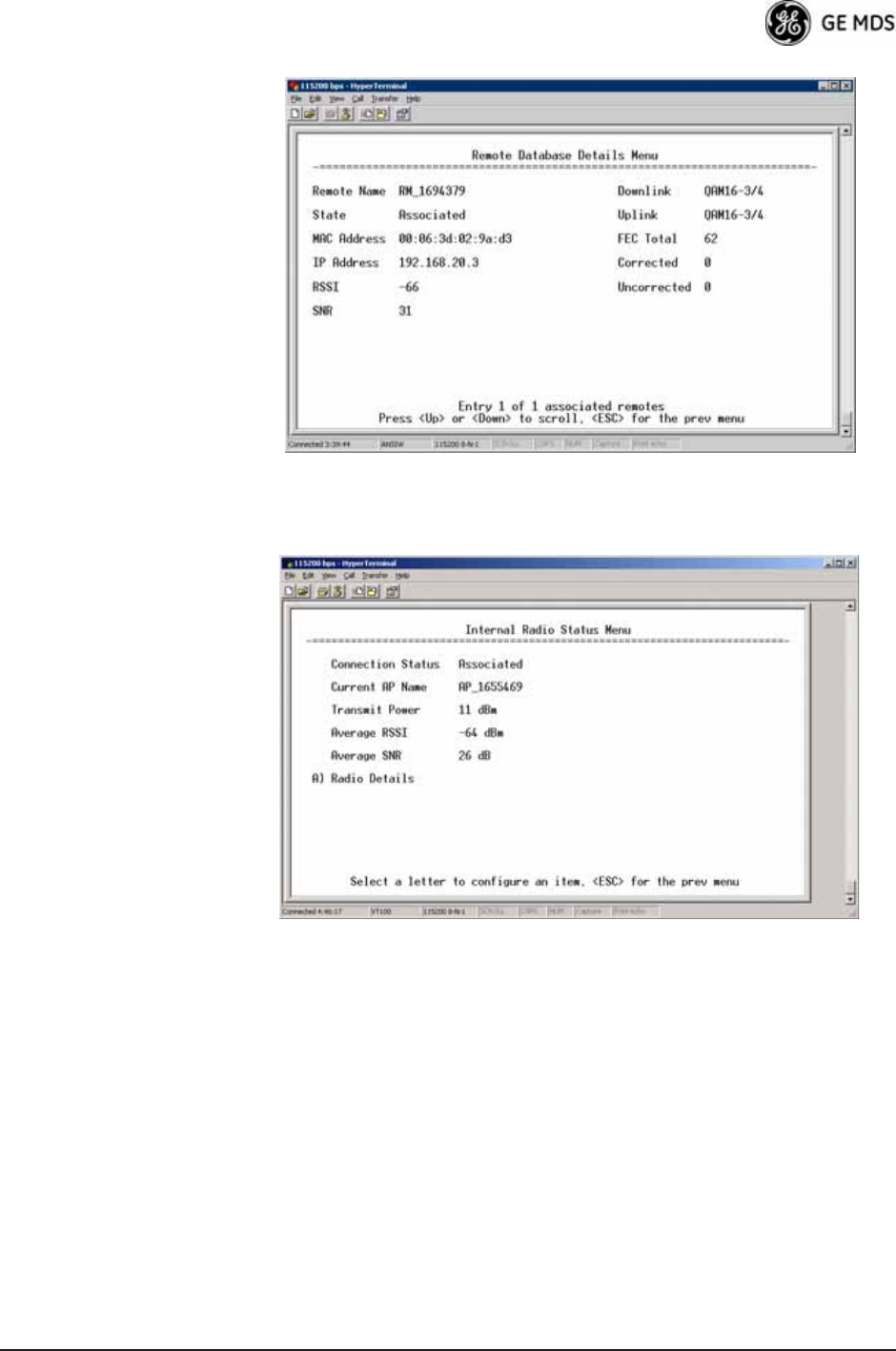
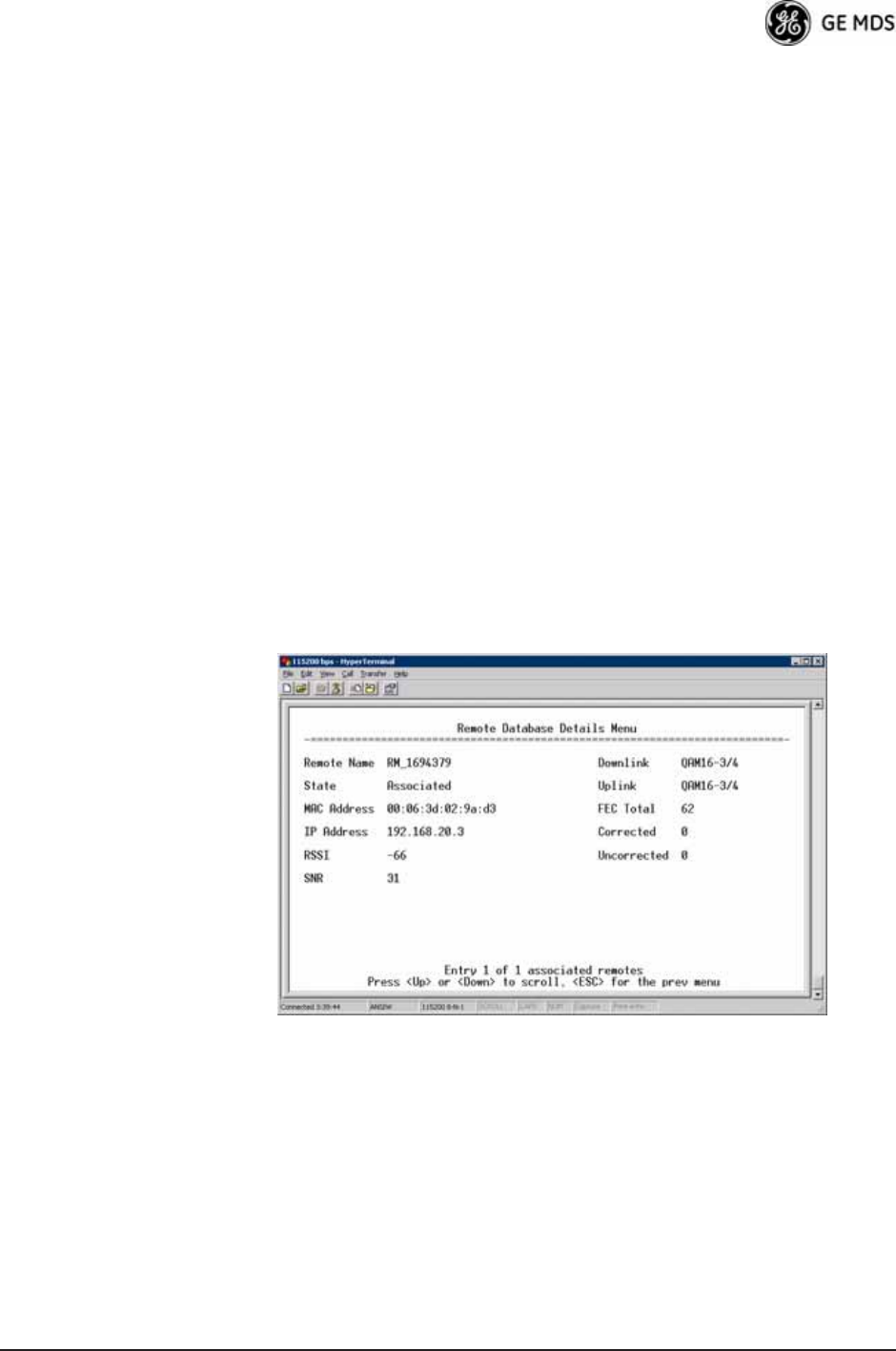
Invisible place holder
Figure 3-93. Remote Database Details Menu (AP)
Internal Radio Status Menu (Remote Only)
Invisible place holder
Figure 3-94. Internal Radio Status (Remote Only)
120 Mercury Reference Manual 05-4446A01, Rev. D
Invisible place holder
Figure 3-95. Internal Status Menu
(Remote in Static Hopping mode)
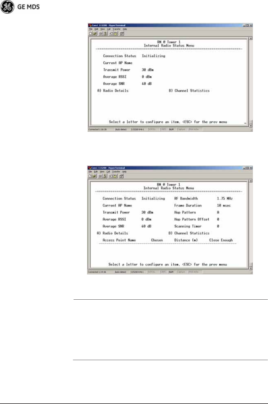
Invisible place holder
Figure 3-96. Internal Radio Status Menu
(Remote in Hopping with Handoffs Mode)
NOTE: In the menu above, the items in the right hand column are
displayed on Remotes only, when they are in Hopping with
Handoffs mode. This allows viewing of the settings the
Remote is using to connect to each AP in the AP Locations
File. See Frequency Control Menu on Page 65 for explanations
of these items. Exception: The Scanning Timer parameter is
unique to the screen shown in Figure 3-96, and is explained
below.
•Connection Status—Indicates whether or not the Remote station
has associated with an AP.
[Associated, Scanning, Ranging, Connecting, Authorizing]
•Current AP Name—Shows the Device Name of the current AP.
05-4446A01, Rev. D Mercury Reference Manual 121
•Transmit Power—Shows the RF power output from the transmit-
ter. The AP changes the transmit power of the Remote to match
the desired receive power at the APs receiver. This provides
end-to-end power control.
•Average RSSI—Shows average received signal strength indica-
tion (RSSI) of incoming RF signals, displayed in dBm.
•Average SNR—Shows average signal-to-noise-ratio (SNR) of
received signals, displayed in dB. This is a measurement of the
quality of the incoming signal. It is possible for incoming sig-
nals to be strong, yet be affected by interference or other noise,
resulting in a low SNR. Use this parameter to help determine the
actual quality of signals.
•Scanning Timer—A timer that runs while the Remote radio tries
to connect to a particular AP. Once this timer reaches the Max
Scanning Time, the Remote tries to connect to the next AP in
the AP Locations File.
•Radio Details—This selection presents a screen (Figure 3-97)
showing key operating details of the transceiver.
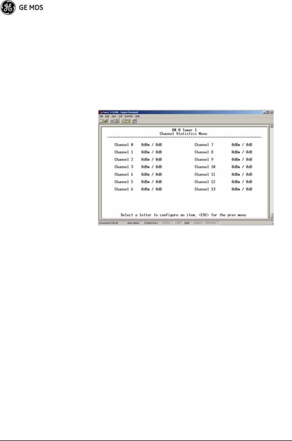
•Channel Statistics—This selection presents a screen
(Figure 3-98) that shows signal quality on a channel-by-channel
basis. Readings are expressed in RSSI dBm and Signal-to-Noise
Ratio (SNR) dB, respectively.Invisible place holder
Figure 3-97. Radio Details Menu
•RSSI—Shows received signal strength indication (RSSI) in
dBm.
•SNR—Shows signal-to-noise ratio (SNR) in dB.
•TX Frequency Offset—Shows the RF carrier shift of the Remote’s
transmitter, measured in Hertz (Hz). The transmitted frequency
is continually reviewed and adjusted to agree with what the AP
expects to see. This optimization results in more efficient oper-
ation, corrects for doppler shift, and results in higher throughput
between AP and Remote stations.
122 Mercury Reference Manual 05-4446A01, Rev. D
•RX Frequency Offset—This is a measurement of how far in fre-
quency the Remote’s receiver has shifted (in Hz) to accommo-
date the incoming signal from the AP.
•Total FEC Count—This parameter shows the total number of For-
ward Error Correction (FEC) blocks handled by the radio.
•Corrected FEC Count—Displays the number of errored blocks
corrected with FEC by the radio.
•Uncorrected FEC Count—Shows the number of errored blocks
that can’t be corrected with FEC by the radio.
Invisible place holder
Figure 3-98. Channel Statistics Menu
3.12 MAINTENANCE/TOOLS MENU
In the course of operating your network, you may wish to upgrade trans-
ceiver firmware to take advantage of product improvements, work with
configuration scripts, conduct “ping” tests of your system, or reset oper-
ating parameters to factory default settings. All of these tasks are per-
formed using the Maintenance/Tools Menu (Figure 3-99). This section
explains how to take advantage of these services.
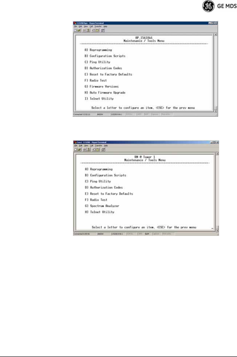
05-4446A01, Rev. D Mercury Reference Manual 123
Invisible place holder
Figure 3-99. Maintenance/Tools Menu (AP)
Invisible place holder
Figure 3-100. Maintenance/Tools Menu (Remote)
(Some versions may show a Scheduled Reboot option, described below)
•Reprogramming—Managing and selecting the unit’s operating
system firmware resources. (See “Reprogramming Menu” on
Page 125)
•Configuration Scripts—Saving and importing data files contain-
ing unit operating parameters/settings. (See “Configuration
Scripts Menu” on Page 130)
•Ping Utility—Diagnostic tool to test network connectivity.
(See “Ping Utility Menu” on Page 134)
•Authorization Codes—Alter the unit’s overall capabilities by
enabling the built-in resources. (See “Authorization Codes” on
Page 135)
•Reset to Factory Defaults—Restores parameters to factory default
settings. (See “Reset to Factory Defaults” on Page 136)
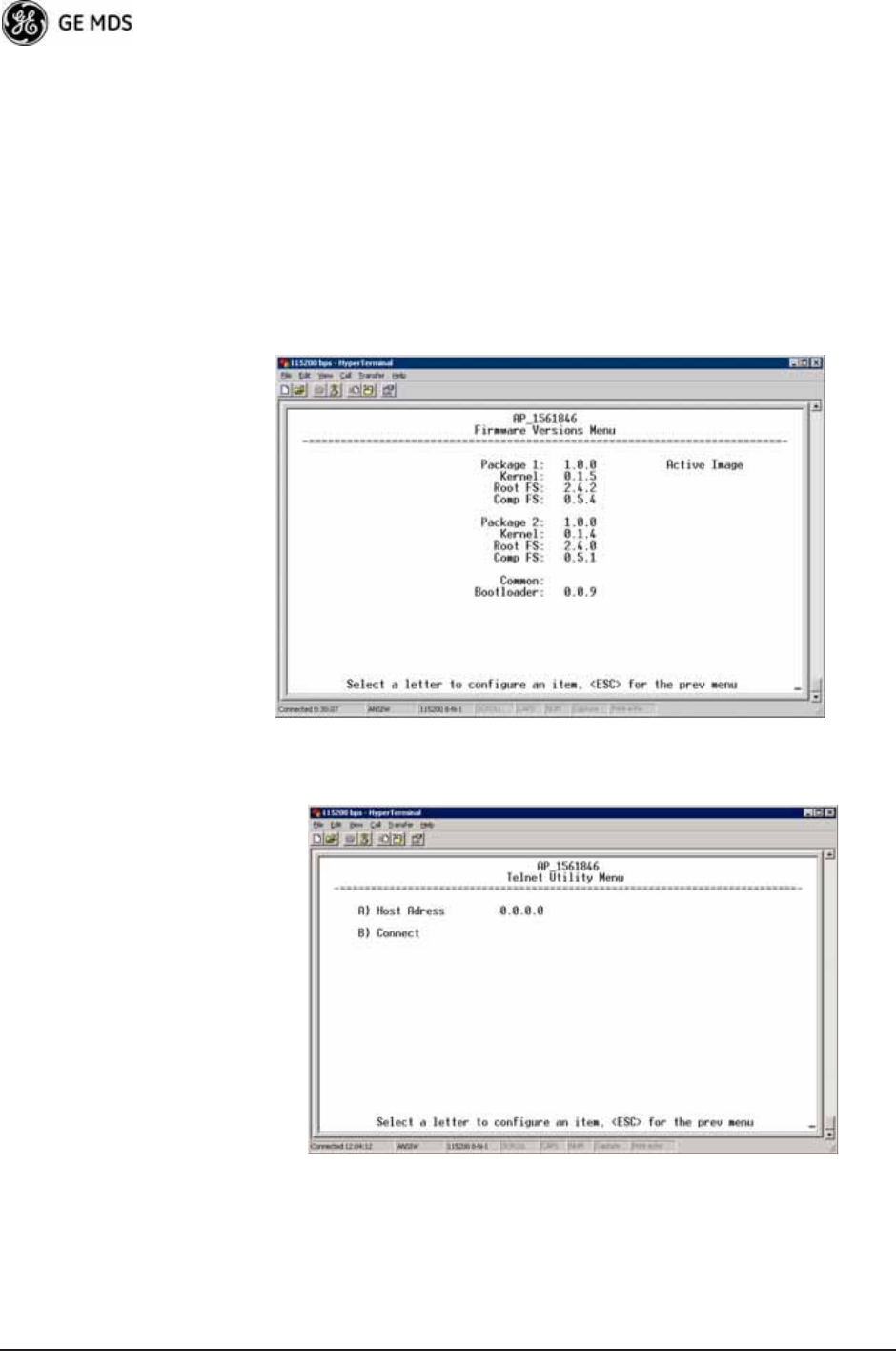
124 Mercury Reference Manual 05-4446A01, Rev. D
•Radio Test—A diagnostic tool for testing RF operation.
(See “Radio Test Menu” on Page 137)
•Firmware Versions—Shows the firmware code versions stored in
the radio and indicates which one is the active image. (See
Figure 3-101 on Page 124.)
•Auto Firmware Upgrade—Brings up a submenu where you can
perform tasks related to loading new firmware. (See “ Auto
Firmware Upgrade Menu (AP Only)” on Page 137.)
•Telnet Utility—A submenu for opening Telnet connections to net-
work devices (Figure 3-102 on Page 124).
Invisible place holder
Figure 3-101. Firmware Versions Menu
Figure 3-102. Telnet Utility Menu
•Host Address—The IP address of the target device.
•Connect—Connect to the target device at the host address.
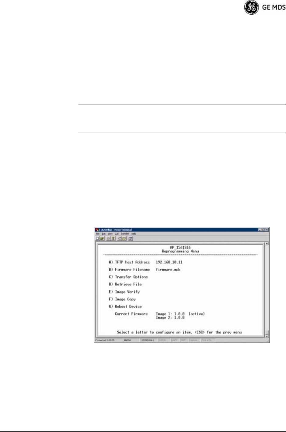
05-4446A01, Rev. D Mercury Reference Manual 125
Reprogramming Menu
The factory sometimes offers upgrades to the transceiver firmware.
Loading new firmware into the unit will not alter any privileges pro-
vided by Authorization Keys and does not require you to take the trans-
ceiver off-line until you want to operate the unit with the newly installed
firmware image.
Firmware images are available free-of-charge at:
www.GEmds.com/Resources/TechnicalSupport/
NOTE: Always read the release notes for downloaded firmware. These
notes contain important information on compatibility and any
special steps needed for proper installation.
All units and versions have two resident images. Version 1.4.4 had
two.mpk files, one for the Access Point and one for the Remote. As of
version 2.1.0, there is only one mpk file which you can use with both
Access Points and Remotes.
The transceiver has two copies of the firmware (microprocessor code)
used for the operating system and applications. One copy is “active” and
the second is standing by, ready to be used once activated. You can load
new firmware into the inactive position and place it in service whenever
you desire.
Invisible place holder
Figure 3-103. Reprogramming Menu (AP)
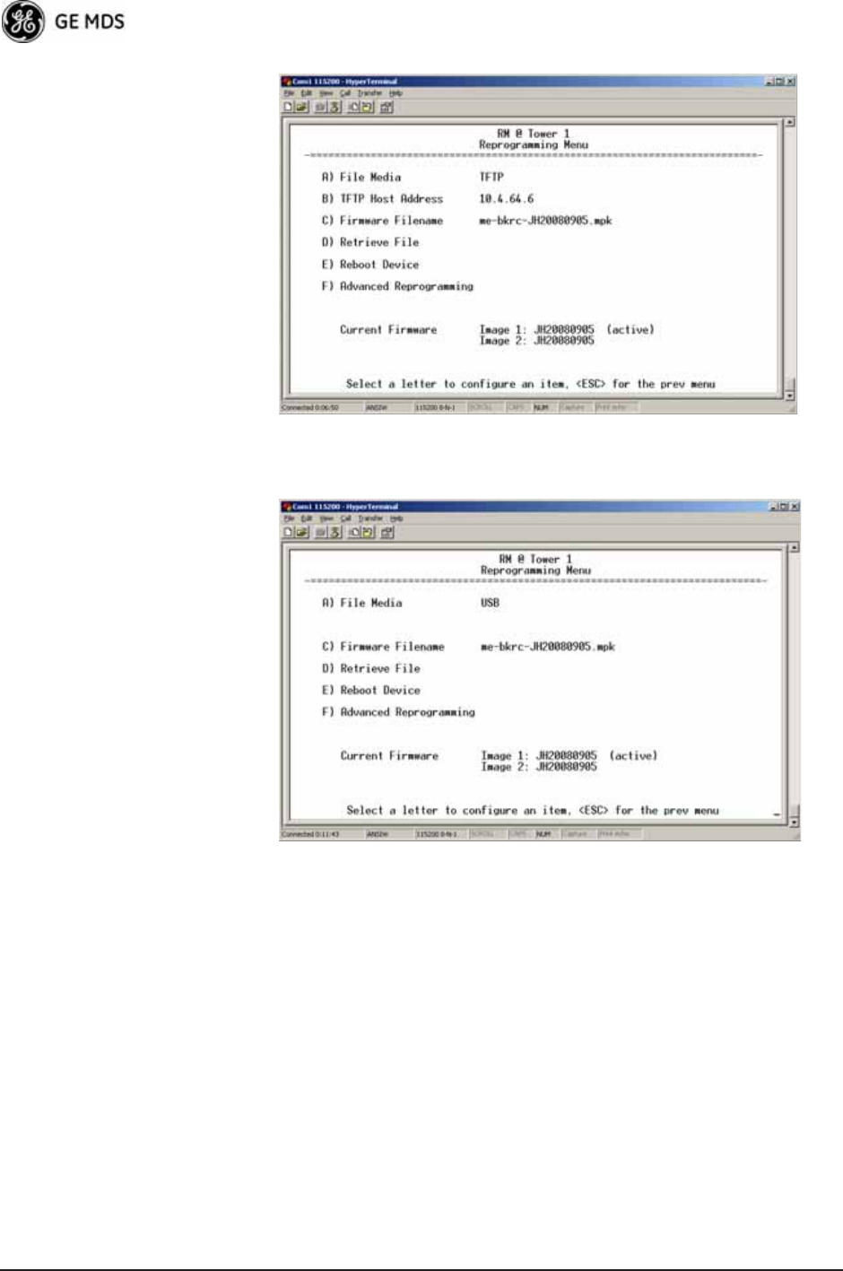
126 Mercury Reference Manual 05-4446A01, Rev. D
Invisible place holder
Figure 3-104. Reprogramming Menu
(Firmware 3.0 Remote Only, TFTP Mode)
Invisible place holder
Figure 3-105. Reprogramming Menu
(Firmware 3.0 Remote Only, USB Mode)
•File Media—A selection of methods for transferring files to and
from the radio. On firmware version 3.0 radios, the options are
TFTP and USB.
•TFTP Host Address—IP address of the host computer from which
to get the file. [Any valid IP address] This same IP address is used
in other screens/functions (reprogramming, logging, etc.).
Changing it here also changes it for other screens/functions.
•Firmware Filename—Name of file to be received by the TFTP
server. [Any 40-character alphanumeric string] Verify that this cor-
responds to the TFTP directory location. May require sub-direc-
tory, for example: me-bkrc-2_1_0.mpk.
•Transfer Options—A menu for configuring the TFTP transfer.

05-4446A01, Rev. D Mercury Reference Manual 127
•Retrieve File—Initiates the file transfer from the TFTP server.
The new file is placed into inactive firmware image. [Y, N ]
•Image Verify—Initiate the verification of the integrity of firm-
ware file held in unit.
•Image Copy—Initiate the copying of the active firmware into the
inactive image.
•Reboot Device—Initiates rebooting of the transceiver. This will
interrupt data traffic through this unit, and the network if per-
formed on an Access Point. Intended to be used for switching
between firmware images 1 and 2.
•Advanced ReprogrammingAdvanced configuration options for
TFTP transfer of firmware files. See Figure 3-106 and related
text descriptions.
•Current Firmware—Displays the versions of firmware images
installed in the transceiver and shows whether Image 1 or Image
2 is currently active.
NOTE: See Upgrade Procedure on Page 129 for details on setting up
the TFTP server.
Invisible place holder
Figure 3-106. Advanced Reprogramming Menu
•TFTP Timeout—View/set the time (in seconds) where no activity
results in a TFTP timeout condition.
•TFTP Block Size—The data size of each TFTP block being trans-
ferred to the radio during firmware upgrade.
•Image Verify—Initiate the verification of the integrity of firm-
ware file held in unit.
•Image Copy—Initiate the copying of the active firmware into the
inactive image.
•Firmware Versions—Shows the available versions of firmware
code for operation of the radio.
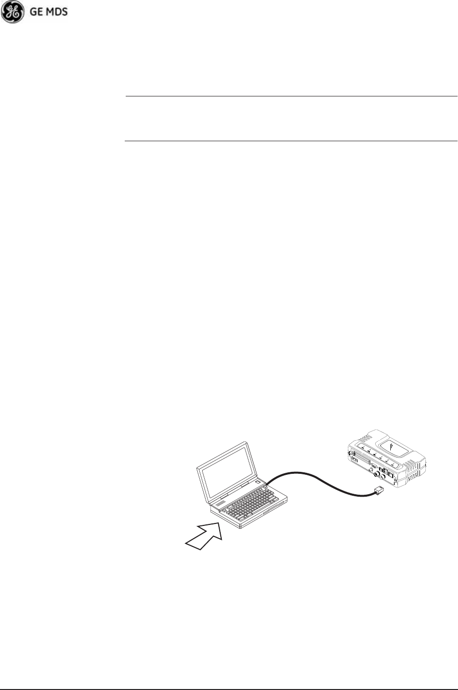
128 Mercury Reference Manual 05-4446A01, Rev. D
3.12.1 Installing Firmware via TFTP
Firmware images are available free-of-charge at:
www.GEmds.com/Resources/TechnicalSupport/.
NOTE: You may not install AP firmware in Remote radios, or
vice-versa. This was only possible for early (pre-version 2.1.0)
firmware.
To install firmware by TFTP, you need:
• A PC with a TFTP server running
• The IP address of the PC running the TFTP server
• A valid firmware file
The IP address of the radio can be found under the Management
System’s Starting Information Screen. (See “Starting Information Screen”
on Page 42.)
A TFTP server is available on the GE MDS Web site at:
www.GEmds.com/Resources/TechnicalSupport/.
TIP: If you do not know your computer’s address on a Windows PC, you
can use the RUN function from the Start menu and enter winipcfg or
ipconfig to determine your local PC’s IP address.
There are several alternatives to connecting the transceiver for firmware
upgrades. Figure 3-107 and Figure 3-108 show two variations. It is
essential that all equipment be on the same subnet.
Invisible place holder
Figure 3-107. Firmware Upgrade SetupOption 1
(TFTP Server and Firmware File on Same CPU)
LAN
PORT
LOCAL WINDOWS PC
WITH CONFIG. FILES
IP ADDRESS: 172.0.0.A
IP ADDRESS: 172.0.0.B
TFTP
SERVER
& TELNET
TRANSCEIVER
C
R
O
S
S
-
O
V
E
R
C
A
B
L
E
INITIATE UPLOAD
FROM HERE
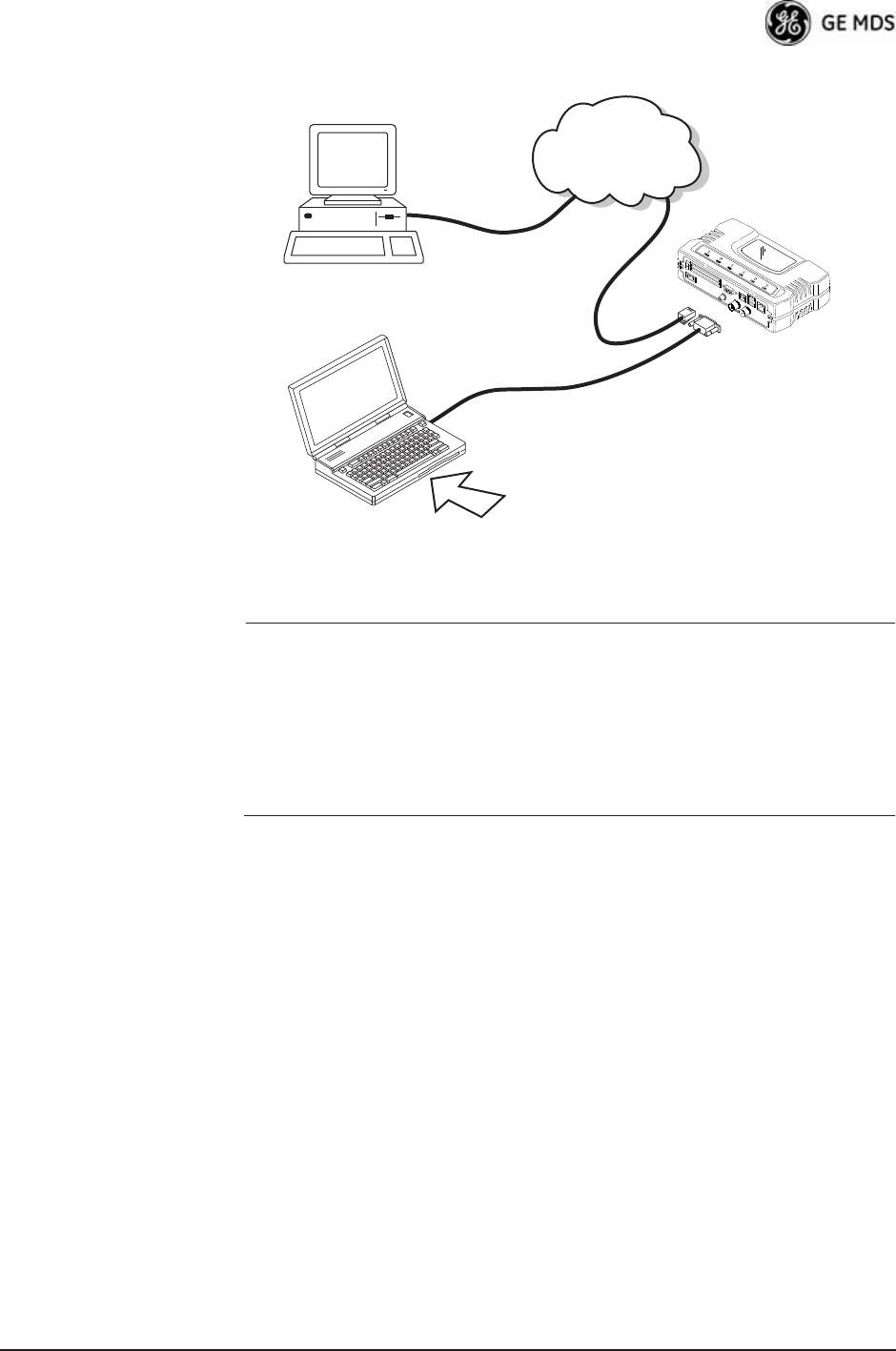
05-4446A01, Rev. D Mercury Reference Manual 129
Invisible place holder
Figure 3-108. Firmware Upgrade SetupOption 2
(TFTP Server and Firmware File on Remote Server)
NOTE: The LAN and COM1 ports share a common data channel when
loading firmware over-the-air. Transferring the radio firmware
image file (≈ 6 MB) might take several minutes depending on
traffic between the TFTP server and the transceiver.
Regardless of your connection to the transceiver, loading firm-
ware/configuration files into the unit’s flash memory is much
slower than loading software onto a PC hard drive or RAM.
Upgrade Procedure To load a new firmware file (filename.mpk) into the transceiver, use the
following procedure:
1. Launch a TFTP server on a PC connected either directly or via a
LAN to the Ethernet port (LAN) of the radio. Point the server
towards the directory containing the firmware image file.
2. Connect to the Management System by whichever means is conve-
nient: browser or Telnet via the LAN, or Terminal emulator via the
COM1 port.
3. Go to the MS Reprogramming Menu.
(Main Menu>>Maintenance Menu>>Reprogramming Menu)
4. Fill in the information for the:
•TFTP Host Address—IP Address of server (host computer) run-
ning TFTP server.
•Firmware Filename—Name of file (filename.mpk) to be down-
loaded from the TFTP server holding the firmware file.
TRANSCEIVER
IP ADDRESS: 172.0.0.B
TFTP
SERVER ETHERNET
PORT
COM1
PORT
(DCE)
INITIATE UPLOAD
FROM HERE
REMOTE PC
W/FIRMWARE FILES
HUB/LAN/WAN/MAN
TCP/IP
LAN
PORT
COM1, 2, ETC.
(DTE)
IP ADDRESS: 172.0.0.A
LOCAL WINDOWS PC
IP ADDRESS: w.x.y.z
TERMINAL
PROGRAM
9
-
PI
NS
E
R
I
A
L
C
A
B
L
E
ST
RA
IG
H
T-T
H
R
U
C
A
BL
E

130 Mercury Reference Manual 05-4446A01, Rev. D
5. Download the firmware file from the TFTP server into the trans-
ceiver.
(Main Menu>>Maintenance Menu>>Reprogramming Menu>>Retrieve File)
Status messages on the transfer are posted on the Management Sys-
tem screen.
NOTE: The new firmware image file that replaces the “Inactive
Image” file is automatically verified.
6. Reboot the transceiver.
Main Menu>>Maintenance Menu>>Reprogramming Menu>>Reboot Device
7. Test the transceiver for normal operation.
End of Procedure
Error Messages During File Transfers
It is possible to encounter errors during a file transfer. In most cases,
these can be corrected by performing the actions described in Table 3-9.
Configuration Scripts Menu
A configuration script file contains all of a radio’s setable parameters
that are accessible through the menu interface, with a few exceptions. A
configuration script file is in plain text format and can be easily edited
in any text program.
Configuration scripts can be helpful in several ways. Three common
uses for them are:
Table 3-9. Common Errors During TFTP Transfer
Error Message Likely Cause/Corrective Action
Invalid File Type Indicates that the file is not a valid firmware
file. Locate proper file and re-load.
File not found Invalid or non-existent filename on TFTP
server.
Invalid file path Invalid or non-existent file path to TFTP
server.
Timeout TFTP transfer time expired. Increase the
timeout value.
Flash Error Flash memory error. Contact factory for
assistance.
Bad CRC Cyclic Redundancy Check reporting a
corrupted file. Attempt to re-load, or use a
different file.
Version String Mismatch Invalid file detected. Attempt to re-load, or use
a different file.
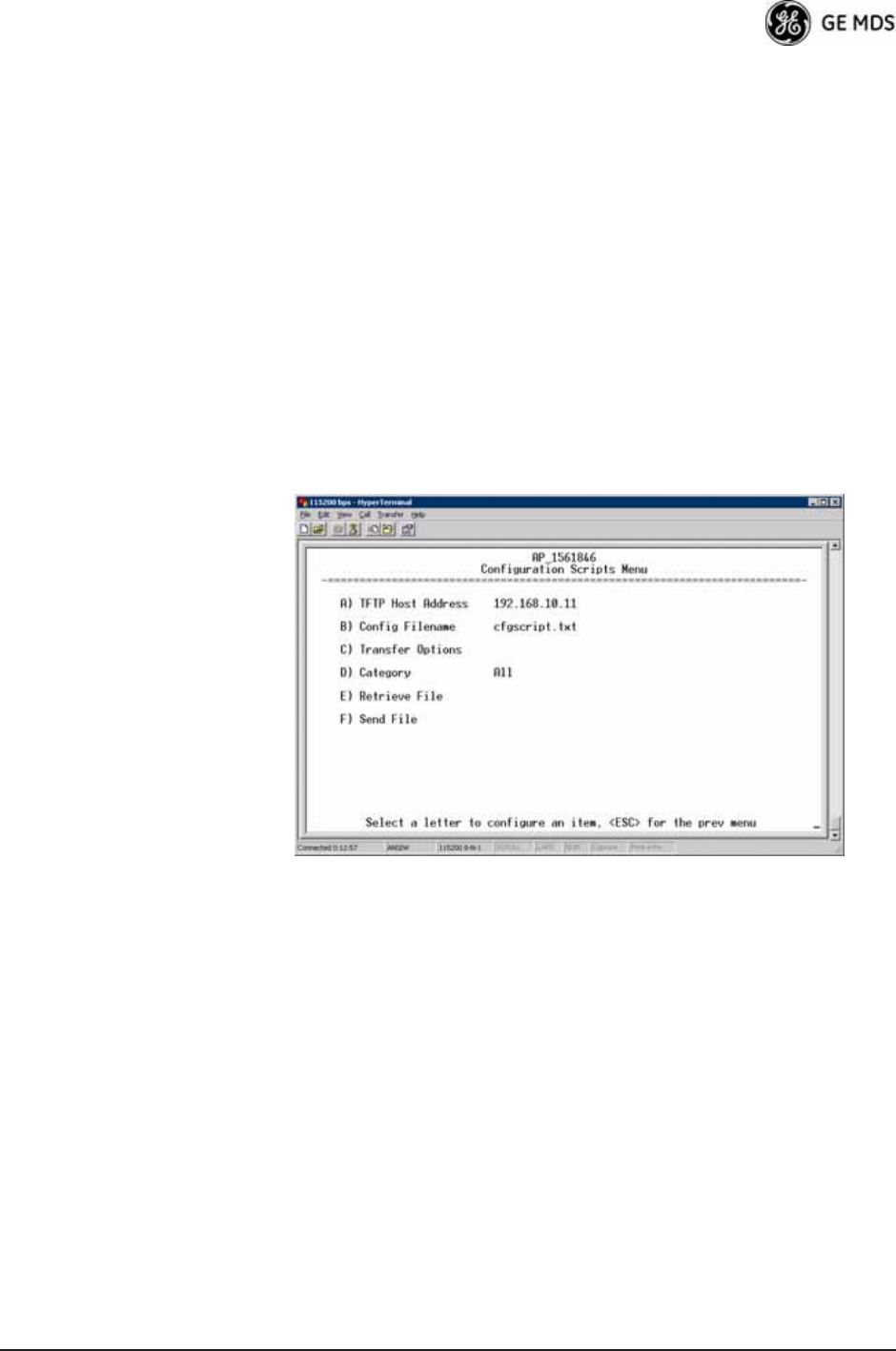
05-4446A01, Rev. D Mercury Reference Manual 131
• To save “known-good” configuration files from your radios.
These can be used for later restoration if a configuration prob-
lem occurs, and it is unclear what parameter is causing the issue.
• To facilitate the rapid configuration of a large number of radios.
• To provide troubleshooting information when you contact the
factory for technical support. A technician can often spot poten-
tial problems by reviewing a configuration file.
How Configuration Files Work
When a configuration script file is downloaded to a radio (Retrieve File),
the radio executes the parameters as commands and takes the values
contained in it. When a configuration script file is uploaded from the
radio (Send), it contains the current values of the radio’s configuration
parameters. Figure 3-109 on Page 131 shows the Configuration Scripts
Menu.
Invisible place holder
Figure 3-109. Configuration Scripts Menu
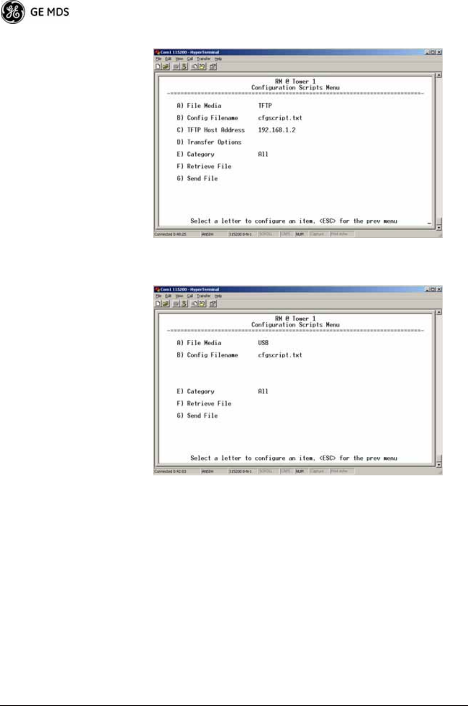
132 Mercury Reference Manual 05-4446A01, Rev. D
Invisible place holder
Figure 3-110. Configuration Scripts Menu
(Firmware 3.0 Remote Only, TFTP mode)
Invisible place holder
Figure 3-111. Configuration Scripts Menu
(Firmware 3.0 Remote Only, USB mode)
•File Media—A selection of methods for transferring files to and
from the radio. On firmware version 3.0 radios, the options are
TFTP and USB.
•Config Filename—Name of file containing this unit’s configura-
tion profile that will be transferred to the TFTP server. The con-
figuration information is in plain-text ASCII format.
[Any 40-character alphanumeric string] May require a sub-direc-
tory, for example: config\mercury-config.txt. (See “Configuration
Scripts Menu” on Page 130 for more information.)

05-4446A01, Rev. D Mercury Reference Manual 133
NOTE: The filename field is used to identify the desired incoming file
and as the name of the file exported to the TFTP server. Before
exporting a unit’s configuration, name it in a way that reflects
the radio’s services or other identification.
•TFTP Host Address—IP address of the computer on which the
TFTP server resides. [Any valid IP address]
•Transfer Options—A menu for configuring the TFTP transfer.
•Category—The category of parameters to send or receive.
•Retrieve File—Initiate the file transfer of the configuration file
from TFTP server into the transceiver.
•Send File—Initiate the file transfer from the transceiver’s current
configuration file to TFTP server.
NOTE: See “Upgrade Procedure” on Page 129 for details on setting
up the TFTP server.
Sample of Configuration Script File
A sample configuration script file is provided as part of every firmware
release. Firmware images and sample files are available free-of-charge
at: www.GEmds.com/Resources/TechnicalSupport/.
The name of the specific file includes the firmware revision number,
represented by the “x” characters in the following example:
mercury-config-x_x_x.txt.
Editing Configuration Files
Once a Remote unit’s operation is fine-tuned, use the Configuration
Scripts Menu on Page 130 to save a copy of the configuration onto a PC.
Once the file is saved on the PC, you can use it as a source to generate
modified copies adjusted to match other devices. Modify the configura-
tion files using a text editor or an automated process. (These applica-
tions are not provided by GE MDS).
We recommend that you review and update the following parameters for
each individual unit. Change other parameters as necessary. Save each
resulting file with a different name. We recommend using directories
and file names that reflect the location of the unit to facilitate later iden-
tification.
Table 3-10. Common User-Alterable Parameters
Field Comment Range
IP Address Unique for each individual radio. Any legal IP address
IP Gateway May change for different groups or
locations.
Any legal IP address
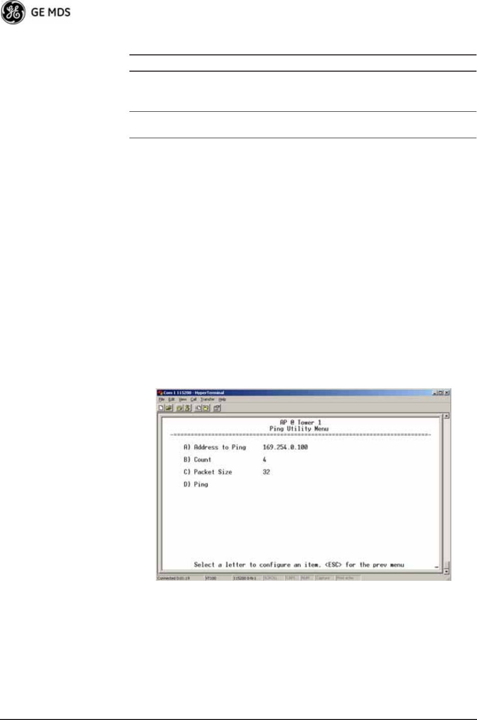
134 Mercury Reference Manual 05-4446A01, Rev. D
Editing Rules • Only include parameters you want to change from the default
value.
• Change only the parameter values.
• Capitalization counts in some field parameters.
• Comment Fields:
a. Edit or delete anything on each line to the right of the
comment delineator, the semicolon (;).
b. Comments can be of any length, but must be on the same
line as the parameter, or on a new line that begins with a
semicolon character.
c. Comments after parameters in files exported from a trans-
ceiver do not need to be present in your customized files.
• Some fields are read-only. These are designated by “(RO)” in
the configuration sample file.
Ping Utility Menu Invisible place holder
Figure 3-112. Ping Utility Menu
•Address to Ping—Address to send a Ping. [Any valid IP address]
•Count—Number of Ping packets to be sent.
•Packet Size—Size of each Ping data packet (bytes).
Device Name Should reflect a specific device.
This information will appear in
Management System headings.
Any 20-character
alphanumeric string
Location Used only as reference for network
administration.
Any 40-character
alphanumeric string
Table 3-10. Common User-Alterable Parameters (Continued)
Field Comment Range
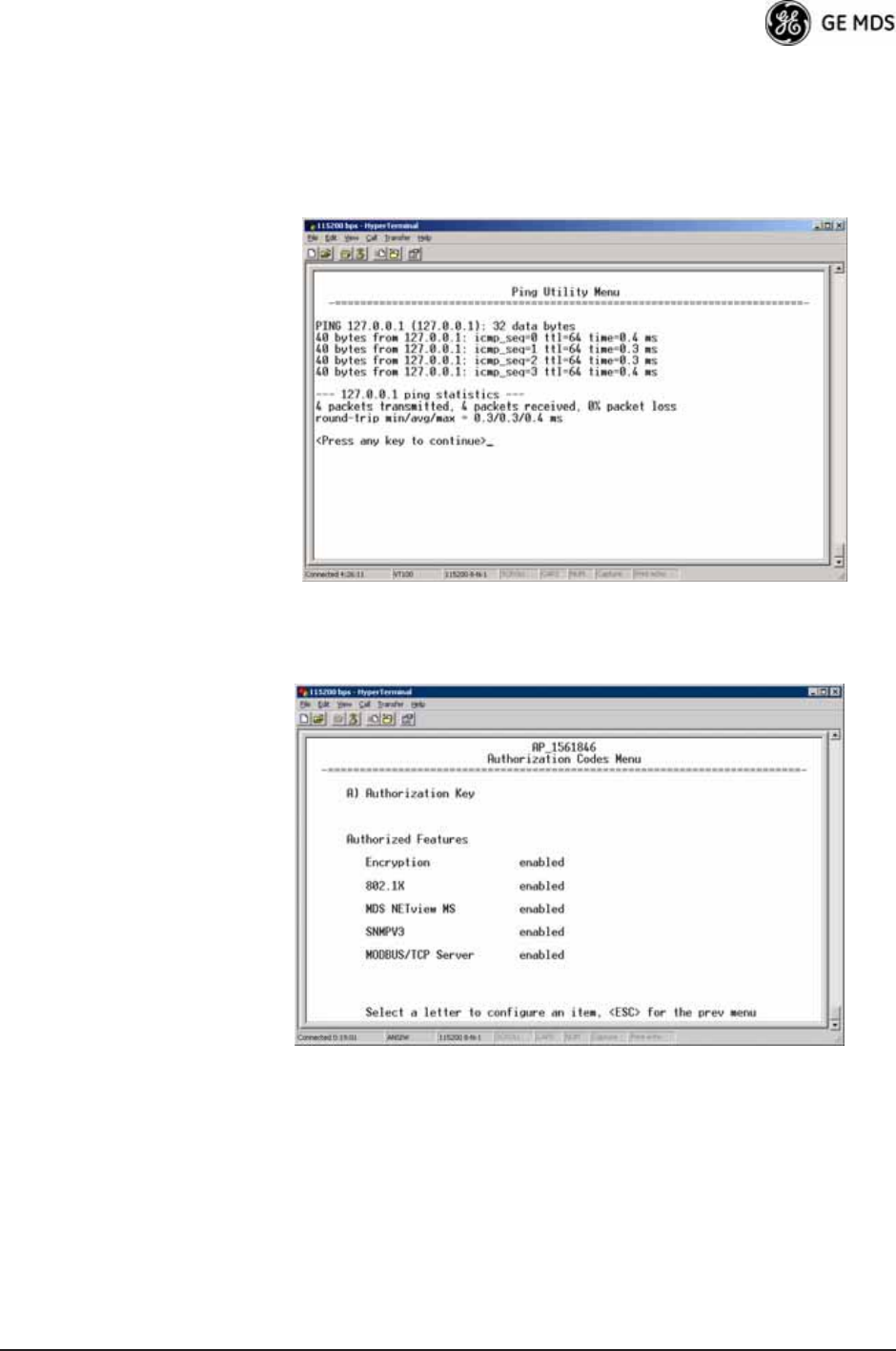
05-4446A01, Rev. D Mercury Reference Manual 135
•Ping—Send Ping packets to address shown on screen.
This screen is replaced with a detailed report of Ping activity
(see example in Figure 3-113). Press any key after viewing the
results to return to this menu.
Invisible place holder
Figure 3-113. Ping Results Screen
Authorization Codes Invisible place holder
Figure 3-114. Authorization Codes Menu
•Authorization Key—For entering an Authorization Key into the
transceiver’s non-volatile memory.
•Authorized Features—List of the transceiver’s authorized fea-
tures. Each item shows enabled or disabled according to the set-
tings allowed by the Authorization Key entered into the radio.
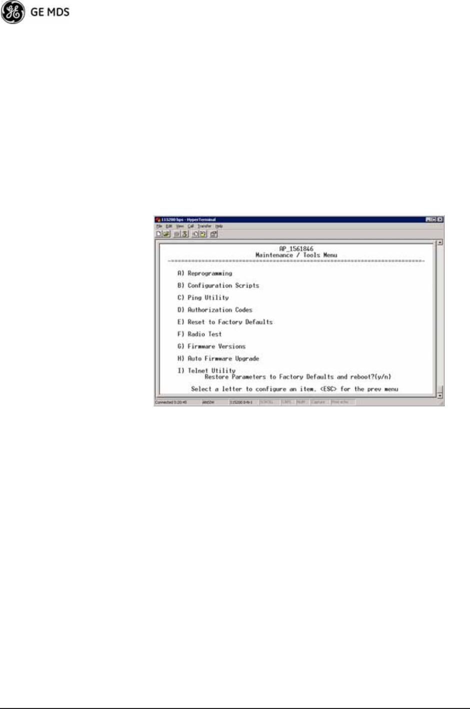
136 Mercury Reference Manual 05-4446A01, Rev. D
Reset to Factory Defaults
Use the Reset to Factory Defaults selection on the Maintenance/Tools
Menu to return all configurable settings to those set at the factory prior
to shipping. Use this selection with caution, as you will lose any custom
settings you have established for your transceiver, and will need to
re-enter them using the menu system.
To prevent accidental use of the command, a “challenge” question is
presented at the bottom of the screen when this choice is selected (see
Figure 3-115 on Page 136). To proceed, enter y for yes or n for no, and
then press Enter. (You may also press the Escape key on your keyboard
to exit this command without making any changes.)
Invisible place holder
Figure 3-115. Reset to Factory Defaults Action
(Note challenge question at bottom of screen)
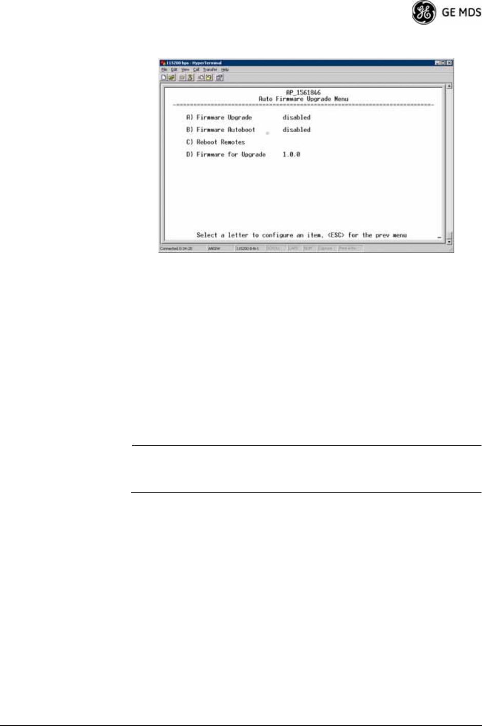
05-4446A01, Rev. D Mercury Reference Manual 137
3.12.2 Auto Firmware Upgrade Menu (AP Only)
Invisible place holder
Figure 3-116.Auto Firmware Upgrade Menu
•Firmware Upgrade—Causes all of the Remotes associated to this
AP to read the AP’s specified (by Firmware for Upgrade) firmware
version (active or inactive), and download it via TFTP to the
inactive image if the Remote does not already have that firm-
ware version.
•Firmware Autoboot—Boot connected remotes to Firmware for
Upgrade (see below).
•Reboot Remotes—Determines how a Remote behaves once it has
downloaded new firmware from the AP as part of an
auto-upgrade. When enabled, the Remotes reboot to the new
firmware.
NOTE: To use the Auto Upgrade/Reboot feature, both the AP and
Remotes must already be running version 2.1.0 or newer firm-
ware.
•Firmware for Upgrade—Specifies the firmware version that the
Remotes should download, if they do not already have it.
Radio Test Menu
Using this menu, you can manually key the radio transmitter for perfor-
mance checks and set several parameters that will be used when the
Radio Mode is set to Test.
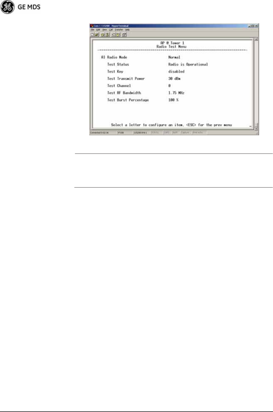
138 Mercury Reference Manual 05-4446A01, Rev. D
Invisible place holder
Figure 3-117. Radio Test Menu
NOTE :Using Test Mode disrupts traffic through the radio. If the unit
is an Access Point, it will disrupt traffic through the entire
network. The Test Mode function is automatically limited to
10 minutes. Only use Test Mode for brief measurements.
•Radio Mode—Sets/displays the radio’s operating mode. To
change the setting, press A on the PC’s keyboard and press the
Spacebar to toggle between the two settings. Press the Enter key
to select the desired state. [Normal, Test; Normal]
•Test Status—This read-only parameter shows the current state of
the radio.
[Radio is Operational, Reconfiguring the Radio, Ready to KEY]
The following parameters are read-only unless A) Radio Mode is first
selected and set to Test. In Test Mode, these items become selectable,
and you can set their entries using the Spacebar or with a numeric entry,
followed by pressing the Enter key.
•Test Key—Sets/displays keying status of the radio’s transmitter.
Use the Spacebar to view selections. [disabled, enabled; disabled]
•Test Transmit Power—Sets/displays the transmitter’s power set-
ting. Make a numerical entry within the allowable range.
[3650 model: +23 dBm max]
[900 model: -30 to +29 dBm]
•Test Channel—Sets/displays the radio’s test channel number.
Make a numerical entry within the allowable range.
[0-13; 0]
•Test RF Bandwidth—Sets/displays the transmitter’s bandwidth for
testing. Use the Spacebar to view selections.
[1.75. 3.5 MHz; 1.75 MHz—additional selections for 3650 model]
•Test Burst Percentage—Sets/displays the percentage of Burst size
to use for testing. Make a numerical entry within the allowable
range. [0-100%; 100]
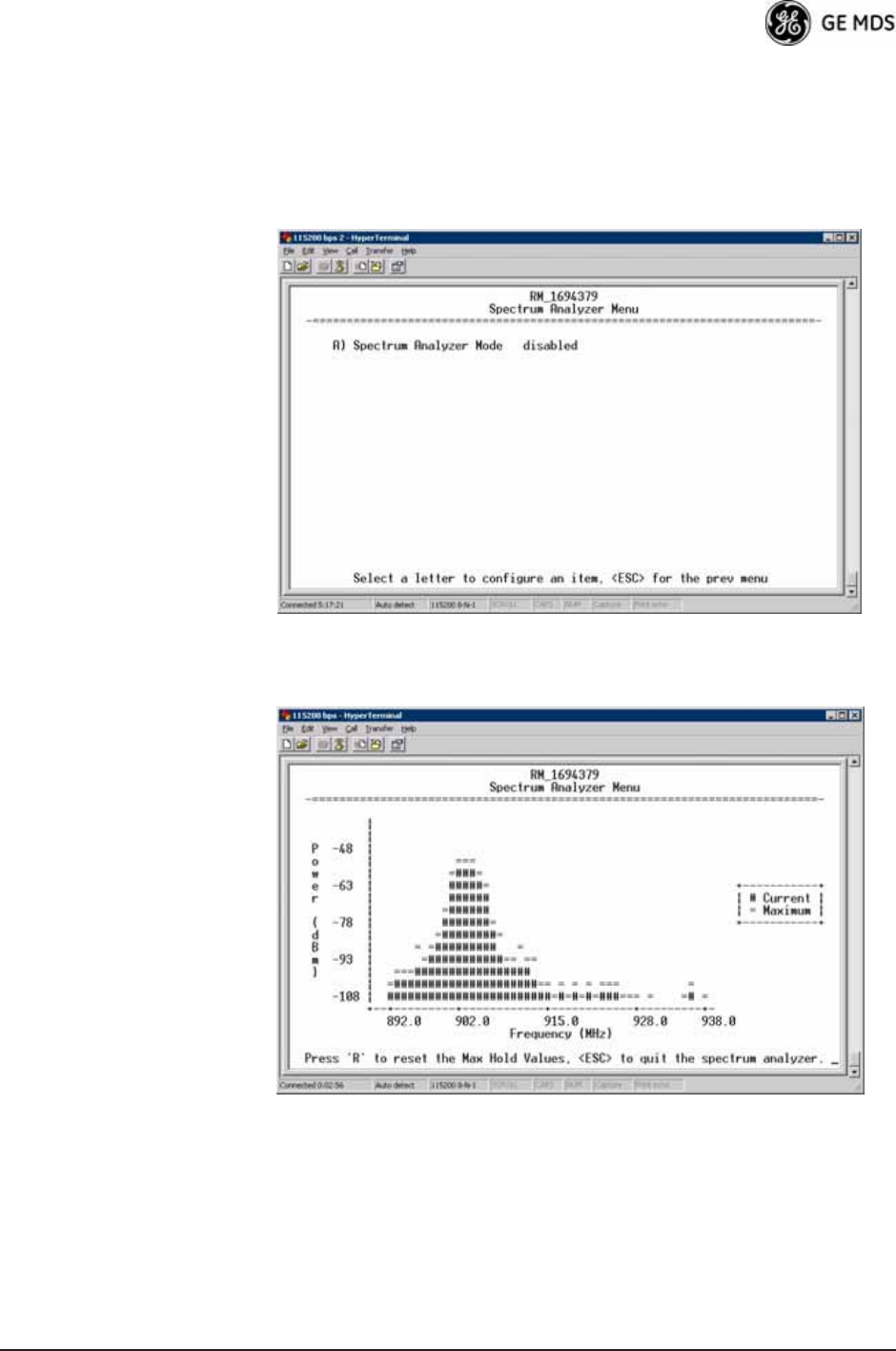
05-4446A01, Rev. D Mercury Reference Manual 139
Spectrum Analyzer Menu (Remote Only)
Using this menu, you can enable or disable the remote’s spectrum ana-
lyzer mode (Figure 3-118 on Page 139). When enabled, the remote dis-
plays through the terminal a spectrum analyzer view of its transmit
power and frequency (Figure 3-119 on Page 139).
Figure 3-118. Spectrum Analyzer Menu
Figure 3-119. Spectrum Analyzer Display
3.13 PERFORMANCE OPTIMIZATION
After checking basic radio operation, you can optimize the network’s
performance. The effectiveness of these techniques varies with the
design of your system and the format of the data being sent.

140 Mercury Reference Manual 05-4446A01, Rev. D
There are two major areas for possible improvement—the radio and the
data network. These sections provide a variety of items to check in both
categories, and in many cases, ways to improve performance.
NOTE: Antennas are one of the most important portions of the wire-
less system. A properly installed antenna with an unobstructed
path to associated stations is the optimal configuration, and
should be among the first items checked when searching for
performance gains.
Stronger signals allow the use of wider bandwidths and higher
data speeds with fewer retries of data transmissions. Time
spent optimizing the antenna systems on both AP and Remote
stations will often have a huge benefit to system performance.
Refer to INSTALLATION PLANNING on Page 161 for addi-
tional recommendations on antenna systems.
Table 3-11 on Page 141 provides suggested settings for typical installa-
tion scenarios. These settings provide a starting point for configuration
of AP and Remote units. Changes might be required to achieve the
desired results in a particular situation.

05-4446A01, Rev. D Mercury Reference Manual 141
Table 3-11. Recommended Settings for Common Scenarios
For Fixed Locations, where best combination of range and throughput is desired.
AP Remote Units Notes
Radio Configuration
Network
Name
User
discretion
User
discretion
AP and Remote must match.
Transmit Power
(AP)/
Max Transmit Power (RM)
30
(3650 model: 23)
30
(3650 model: 23)
dBm In most cases, power can be set to this level
and left alone. Setting it lower helps control
cell overlap.
Receive Power -70 N/A dBm Sets AP receiver for medium gain. Typical
range: -60, -80 dBm.
Frequency Control
Frequency Mode Static Hopping Static Hopping
Frame Duration 20 20 ms Changing to 10 ms lowers latency. 5 and 8
ms selections not functional for this release.
Hop Pattern A, B, C, D A, B, C, D AP and RM must match.
Hop Pattern
Offset
0-13 or 0-6 0-13 or 0-6 AP and RM must match.
Channel
Selection
User
discretion
User
discretion
Disable channels with interference. AP and
RM must match.
TDD Sync Mode GPS Required N/A GPS Antennas must be connected to both
AP and RM.
Advanced Configuration
Adaptive
Modulation
Enabled Enabled
Protection
Margin
33dB
Hysteresis
Margin
33dB
Data
Compression
Enabled Enabled Gives best throughput numbers, but may
hide true performance if only tested with
PING or Text File FTP.
Max
Modulation
QAM/16-3-4 QAM16-3/4 Best combination of range and throughput.
Cyclic Prefix 1/16 N/A Best throughput setting.
Channel
Type
Static N/A Less periodic ranging when channel type is
Static.
ARQ Enabled N/A
ARQ Block Size 256 N/A bytes
ARQ Block
Lifetime
655 N/A ms
These 3 settings make the max. no. of ARQ
retries =9.
(655 ms)/(35 ms + 35 ms = 9.35=>9
ARQ TX
Delay
35 N/A ms
ARQ RX Delay 35 N/A ms
Adaptive Split Enabled N/A Maximizes one-way burst throughput.
Downlink% 50 N/A %If Adaptive Split is disabled, can set
downlink% to 15%–75%.