GE MDS DS-NH900 MDS iNet 900 User Manual 2873A iNET IG Body
GE MDS LLC MDS iNet 900 2873A iNET IG Body
GE MDS >
Contents
- 1. MDS iNet 900 Installation Guide
- 2. User Manual Amended Page for RF Exposure Information
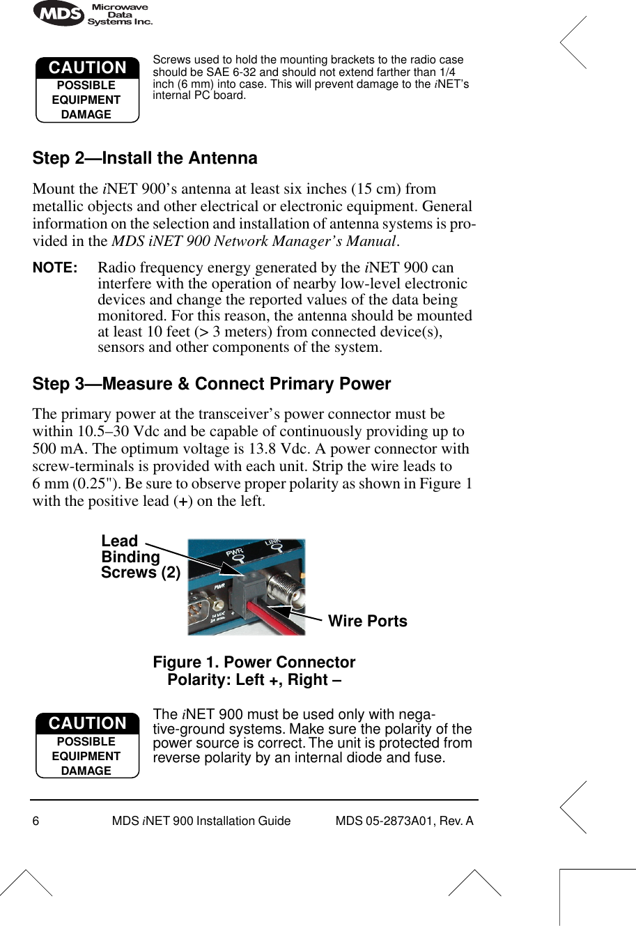
- 3. User Manual Addendum
- 4. user manual
- 5. user manaul pt2
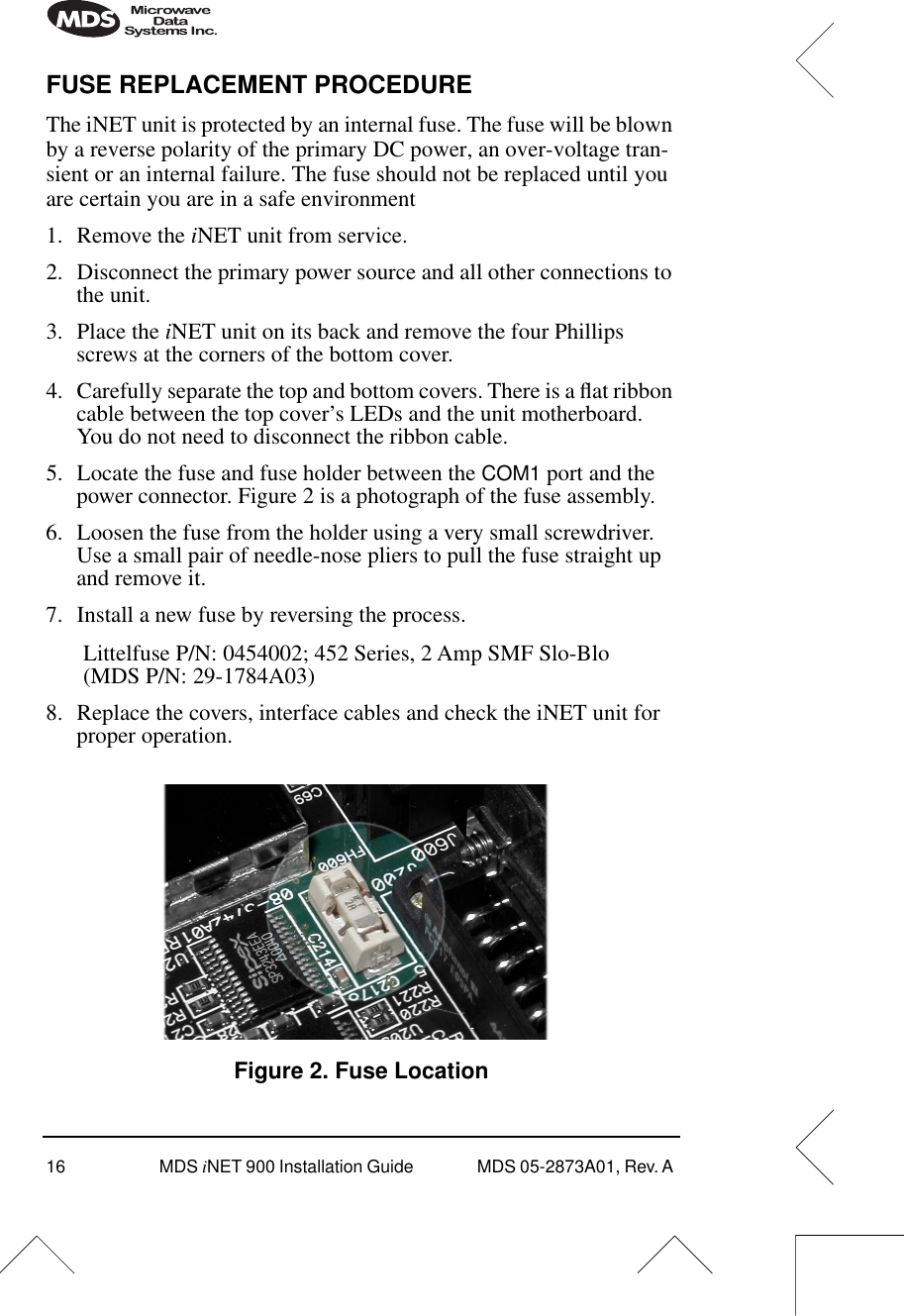
MDS iNet 900 Installation Guide