GE MDS DS-NH900 MDS iNet 900 User Manual 2873A iNET IG Body
GE MDS LLC MDS iNet 900 2873A iNET IG Body
GE MDS >
Contents
- 1. MDS iNet 900 Installation Guide
- 2. User Manual Amended Page for RF Exposure Information
- 3. User Manual Addendum
- 4. user manual
- 5. user manaul pt2
MDS iNet 900 Installation Guide

MDS 05-2873A01, Rev. A MDS
i
NET 900 Installation Guide
1
CONTENTS
OPERATIONAL & SAFETY NOTICES ...................................2
PRODUCT DESCRIPTION .....................................................4
INSTALLATION PLANNING ....................................................5
INSTALLATION .......................................................................5
Step 1—Mount the Transceiver ...................................................5
Step 2—Install the Antenna ........................................................6
Step 3—Measure & Install Primary Power ..................................6
Step 4—Review the Radio’s Configuration .................................7
Step 5—Connect the Data Equipment ........................................6
Step 6—Check for Normal Operation .........................................9
Performance Optimization .........................................................10
USING RSSI TO AIM REMOTE ANTENNAS .......................10
Method 1—For New Network Installations ................................11
Method 2—Adding iNET units to an existing network ...............13
TROUBLESHOOTING ..........................................................14
FUSE REPLACEMENT PROCEDURE ................................16
i
NET SPECIFICATIONS .......................................................17
TECHNICAL ASSISTANCE ..................................................18
FACTORY SERVICE .............................................................18
INSTALLATION REFERENCE CHART ............. (Center Insert)
Copyright Notice
This publication is protected by U.S.A. copyright law. Copyright 2002, Microwave
Data Systems, Inc. All rights reserved.
2 MDS
i
NET 900 Installation Guide MDS 05-2873A01, Rev. A
Serviceability of this Manual
Every reasonable effort has been made to ensure the accuracy of this manual, however
product improvements may result in minor differences between the manual and the
product shipped to you. If you have additional questions or need an exact specification
for a product, please contact our Customer Service Team using the information at the
back of this guide. Microwave Data Systems Incorporated reserves its right to correct
any errors or omissions. Updated information may also be available on our Web site
at www.microwavedata.com. This manual is for the use of professionals to guide them
in the installation, operation and basic system maintenance of the equipment covered.
OPERATIONAL & SAFETY NOTICES
The radio equipment described in this guide emits
radio frequency energy. Although the power level
is low, the concentrated energy from a directional
antenna may pose a health hazard. Do not allow
people to come closer than 20 centimeters (8
inches) to the antenna when the transmitter is
operating in indoor or outdoor installations.
This manual is intended to guide a
professional installer
in installing, operating
and performing basic system maintenance on the described equipment.
FM/UL/CSA Notice
This product is available for use in Class 1, Division 2, Groups A, B, C & D Haz-
ardous Locations. Such locations are defined in Article 500 of the National Fire Pro-
tection Association (NFPA) publication NFPA 70, otherwise known as the National
Electrical Code.
The transceiver has been recognized for use in these hazardous locations by three
independent agencies —Underwriters Laboratories (UL), Factory Mutual Research
Corporation (FMRC) and the Canadian Standards Association (CSA). The UL certi-
fication for the transceiver is as a Recognized Component for use in these hazardous
locations, in accordance with UL Standard 1604. The FMRC Approval is in accor-
dance with FMRC Standard 3611. The CSA Certification is in accordance with CSA
STD C22.2 No. 213-M1987.
FM/UL/CSA Conditions of Approval
The transceiver is not acceptable as a stand-alone unit for use in the hazardous loca-
tions described above. It must either be mounted within another piece of equipment
which is certified for hazardous locations, or installed within guidelines, or conditions
of approval, as set forth by the approving agencies. These conditions of approval are
as follows:
1. The transceiver must be mounted within a separate enclosure that is suitable for
the intended application.
2. The antenna feedline, DC power cable and interface cable must be routed
through conduit in accordance with the National Electrical Code.
3. Installation, operation and maintenance of the transceiver should be in accor-
dance with the transceiver's installation manual, and the National Electrical
Code.
RF Exposure

MDS 05-2873A01, Rev. A MDS
i
NET 900 Installation Guide
3
4. Tampering or replacement with non-factory components may adversely affect the
safe use of the transceiver in hazardous locations, and may void the approval.
Do not disconnect equipment unless power
has been switched off or the area is known
to be non-hazardous.
Refer to Articles 500 through 502 of the
National Electrical Code (NFPA 70) for fur-
ther information on hazardous locations
and approved Division 2 wiring methods.
FCC Notice, U.S.A.
The MDS iNET 900 transceivers comply with Part 15 of the FCC Rules. Operation is
subject to the following two conditions: (1) this device may not cause harmful inter-
ference, and (2) this device must accept any interference received, including interfer-
ence that may cause undesired operation.
Only install this device in accordance with the instructions outlined in this manual.
Failure to comply with these instructions may also void the user’s authority to operate
this device.
Furthermore, this device is intended to be used only when installed in accordance with
the instructions outlined in this manual. Failure to comply with these instructions may
also void the user’s authority to operate this device.
FCC Information
This equipment has been tested and found to comply with the limits for a Class A dig-
ital device, pursuant to Part 15 of the FCC Rules. These limits are designed to provide
reasonable protection against harmful interference when the equipment is operated in
a commercial environment. This equipment generates, uses, and can radiate radio fre-
quency energy and, if not installed and used in accordance with the instruction
manual, may cause harmful interference to radio communications. Operation of this
equipment in a residential area is likely to cause harmful interference in which case
the user will be required to correct the interference at his own expense.
ABOUT THIS MANUAL
This guide presents installation and initial operating instructions for
the MDS
i
NET 900™ transceiver. Following installation, we suggest
keeping this guide near the equipment for future reference.
The scope of this manual is limited to the safe and effective installation
of the unit in typical office or non-hazardous industrial settings. Users
who require optimization of the equipment’s capabilities and oper-
ating range should read the
MDS iNET 900 Network Administrator’s
Manual
, P/N 05-2806A01. This manual provides more in-depth infor-
mation on antenna selection and optimization, and extensive coverage
on user-controllable parameters and diagnostic tools.
EXPLOSION
HAZARD!

4 MDS
i
NET 900 Installation Guide MDS 05-2873A01, Rev. A
The most essential installation information is contained on the
Instal-
lation Reference Chart
found at the center of this manual.
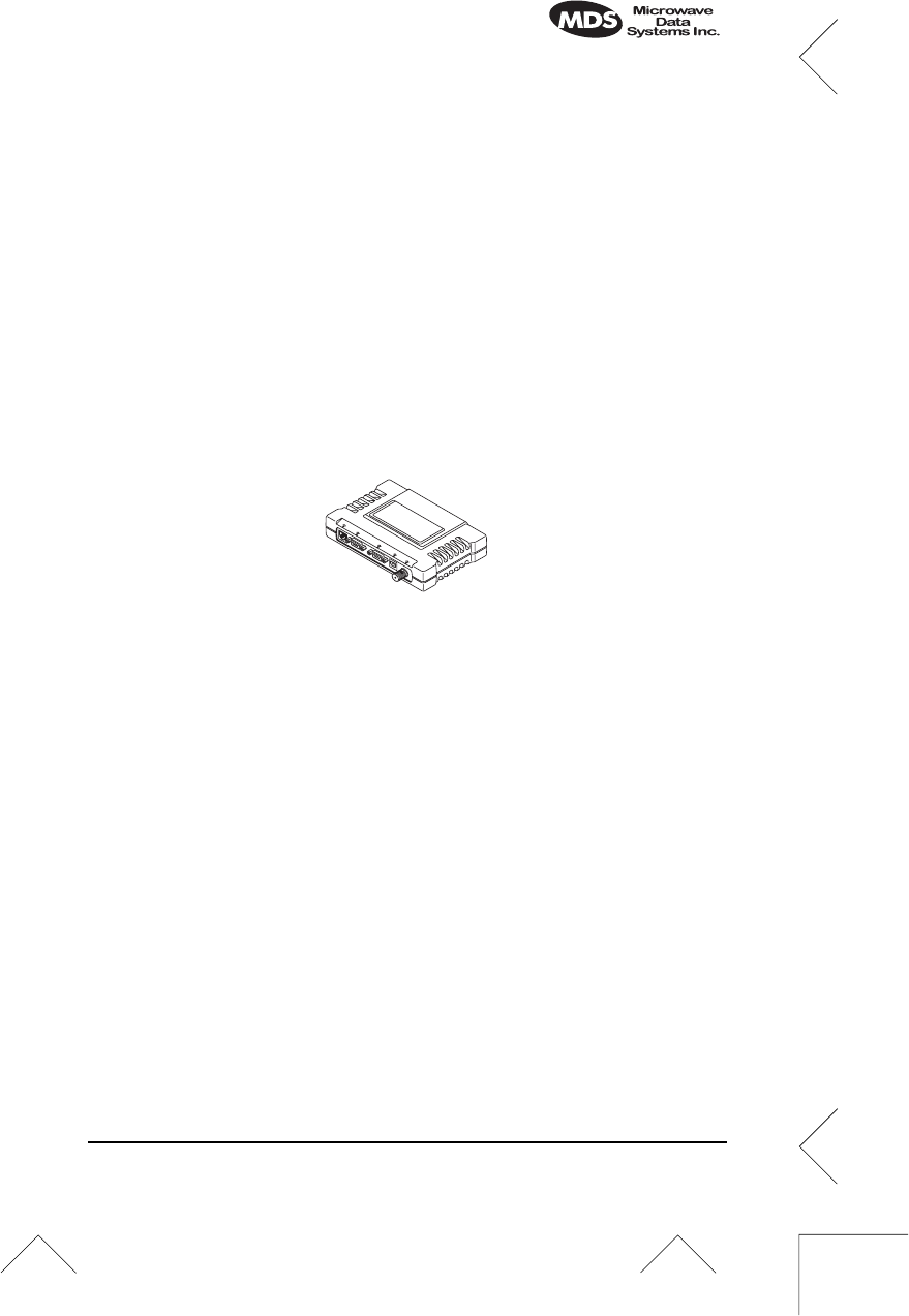
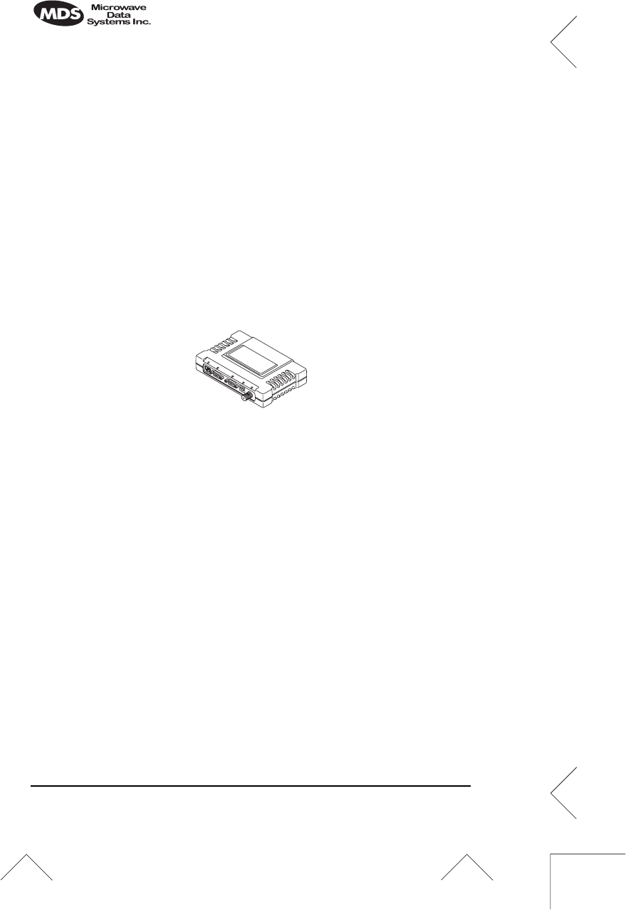
PRODUCT DESCRIPTION
The MDS
i
NET 900 transceiver is designed to provide network man-
agers with a easy-to-install wireless local area network (LAN) services
with plug-and-play hardware.
The unit can be reconfigured for any one of three standard operating
arrangements; some require the use of authorization keys (alphanu-
meric code) purchased from MDS. The model descriptions reflect
their operating mode capabilities. Supported data interface services
are one of three arrangements: 1. Ethernet, 2. Serial, and 3. Ethernet
and Serial. (See Table 1 on page 4 for a summary of core interface ser-
vices.)
The MDS
i
NET 900 transceivers serve as either an “Access Point” or
“Remote”. An Access Point (AP) is a wireless hub that usually pro-
vides connectivity into a wired Ethernet LAN/WAN. From a radio
perspective, an Access Point also serves as the radio network’s
“master station” providing synchronization signaling to all associated
i
NET 900 Remotes (RMT) within its radio network.
Table 1.
i
NET 900 Models and Data Interface Services
Model Variation LAN Data
3
(IP/Ethernet) COM1
Data COM1
Local
MGT
COM2
Data
Access Point
N/A
Yes Yes Yes Yes
Remote… Bridge
1
Yes No Yes No
Serial
Gateway
1
No No Yes Yes
Dual
Gateway
1&2
Yes Yes Yes Yes
NOTES
1. Alternate configurations available via authorization key.
2. Able to be converted to Access Point without authorization key.
(Not currently available.)
3. LAN port provides access to Management System on all models and varia-
tions.

MDS 05-2873A01, Rev. A MDS
i
NET 900 Installation Guide
5
INSTALLATION PLANNING
This section provides tips for selecting an appropriate site, choosing an
antenna system, and reducing the chance of harmful interference.
General Requirements
There are three main requirements for installing the radio—adequate
and stable primary power, a good antenna system, and the correct
interface between the transceiver and the data device. The center
Installation Reference Chart
shows a typical Remote installation.
Access Point stations typically use omnidirectional antennas whereas
Remotes, typically use directional antennas such as Yagis.
INSTALLATION
A typical transceiver product shipment consists of an
i
NET 900 trans-
ceiver, a power connector and a manual. Check the contents against
the packing list attached to the outside of the shipping box.
Below are the basic steps for installing an
i
NET 900 transceiver.
Should further information be required, see “TECHNICAL ASSIS-
TANCE” on page 18 of this manual for information on contacting the
MDS Customer Service Department. You will also find support infor-
mation at the Microwave Data System Web site at www.microwave-
data.com on the Internet.
It is highly recommended that the Access Point unit be installed
first.
With this plan, it will be possible to quickly check the operation of
each associated Remote unit as it is placed on the air.
NOTE:
MDS
i
NET 900 transceivers are shipped from the
factory set to the “Remote Serial Gateway” mode unless
they are marked differently.
Step 1—Mount the Transceiver
Mount the transceiver to a stable surface. (Fasteners/anchors/screws
are not supplied unless specified on the purchase order.) Four threaded
holes are located on the bottom of the radio that are suitable for con-
necting mounting hardware. Use 6-32 x 1/4 inch screws to attach
mounting hardware to the bottom of the radio.
6 MDS
i
NET 900 Installation Guide MDS 05-2873A01, Rev. A
Screws used to hold the mounting brackets to the radio case
should be SAE 6-32 and should not extend farther than 1/4
inch (6 mm) into case. This will prevent damage to the
i
NET’s
internal PC board.
Step 2—Install the Antenna
Mount the
i
NET 900’s antenna at least six inches (15 cm) from
metallic objects and other electrical or electronic equipment. General
information on the selection and installation of antenna systems is pro-
vided in the
MDS iNET 900 Network Manager’s Manual
.
NOTE:
Radio frequency energy generated by the
i
NET 900 can
interfere with the operation of nearby low-level electronic
devices and change the reported values of the data being
monitored. For this reason, the antenna should be mounted
at least 10 feet (> 3 meters) from connected device(s),
sensors and other components of the system.
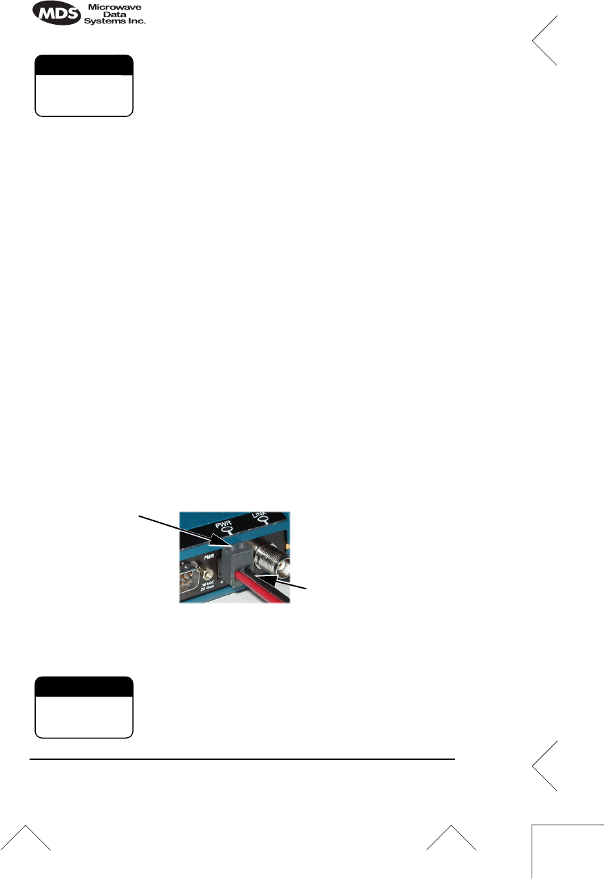
Step 3—Measure & Connect Primary Power
The primary power at the transceiver’s power connector must be
within 10.5–30 Vdc and be capable of continuously providing up to
500 mA. The optimum voltage is 13.8 Vdc. A power connector with
screw-terminals is provided with each unit. Strip the wire leads to
6 mm (0.25"). Be sure to observe proper polarity as shown in Figure 1
with the positive lead (
+
) on the left.
Invisible place holder
Figure 1. Power Connector
Polarity: Left +, Right –
The
i
NET 900 must be used only with nega-
tive-ground systems. Make sure the polarity of the
power source is correct. The unit is protected from
reverse polarity by an internal diode and fuse.
CAUTION
POSSIBLE
EQUIPMENT
DAMAGE
Wire Ports
Lead
Screws (2)
Binding
CAUTION
POSSIBLE
EQUIPMENT
DAMAGE

MDS 05-2873A01, Rev. A MDS
i
NET 900 Installation Guide
7
The power supply used with the transceiver should be equipped with
overload protection (NEC Class 2 rating), to protect against a short cir-
cuit between its output terminals and the transceiver power connector.
NOTE:
It typically takes about 60 seconds for the
i
NET 900 to
power up and be ready for operation.
Step 4—Review the
i
NET 900’s Configuration
Two essential settings for
i
NET 900 transceivers should be known
before placing the unit into service. They are:
•
Device Mode
—Access Point, or Remote (Default)
•
Network Name—
Unique name of the iNET 900 units asso-
ciated with the network (Required)
The Network Name must be programmed to enable
i
NET 900 Remote
units to associate with the Access Point unit.
Several other parameters commonly need to be reviewed and altered
if necessary. They are:
•
IP Address
—Must be a unique number to allow for IP access
through the
LAN
Port (Ethernet).
•
RF Output Power Level
—Check and adjust as necessary for
compliance with FCC guidelines.
(Default = 1 Watt/+30 dBm)
•
Password
—Used for remote access and to use certain
i
NET
Management System features.
NOTE:
The default password is
admin
A unique IP address in the subnet is important if the unit’s
LAN
port
will be used to access the browser-based
i
NET Management System
either locally or by way of a LAN/WAN.
How to Review the
i
NET’s Configuration
The following is a summary of the installation procedure. For more
detailed instructions on using the HTTP (
LAN
Port) and text-based
(
COM1
) Management System, please read the
MDS iNET 900 Net-
work Administrator’s Handbook
. Key parameters are highlighted on
the Management System flowchart on the
Installation Reference
Chart
.

8 MDS
i
NET 900 Installation Guide MDS 05-2873A01, Rev. A
a. Connect a computer’s serial communications port (
COM1
or
COM2
) to the
i
NET
COM1
Port connector. (Data defaults:
19,200 bps/8N1)
b. Launch a terminal emulator program, such as HyperTerminal,
on the computer.
c. Depress the
ENTER
key. The radio will respond with the
start-up screen of the
i
NET Management System.
A password will be required to make any changes to the radio.
(Default =
admin
)
d. Program the
i
NET Network Name.
e. Review other settings and make changes if necessary, such as
the unit password and IP address.
Repeat the above steps for each transceiver in the network.
(See following note)
NOTE:
The Management System supports the use of “configuration
scripts” which can hold complex parameter arrangements.
These scripts aid in uniformly configuring multiple
i
NET
units. These are detailed in the
MDS iNET 900 Network
Administrator’s Handbook
.
Basic
i
NET Configuration Defaults
The Basic Configuration Defaults table on the
Installation Reference
Chart
provides a summary of selected operating parameters’ range
and default values. All of these are available through the
i
NET’s Man-
agement System accessible through a terminal emulator connected to
the
COM1
port or through a browser connected to the
LAN
Port.
Step 5—Connect the Data Equipment
Connect IP/Ethernet-compatible equipment data equipment to the
transceiver’s
LAN
port (10BaseT), or one of the serial ports, depending
on the capability of your
i
NET model. (See Table 1 on page 4.)
Use only the required pins for the application—do not connect any-
thing to unused pins. For Ethernet, use a straight-through Ethernet
cable to connect to a hub or a crossover cable to connect directly to an

MDS 05-2873A01, Rev. A MDS
i
NET 900 Installation Guide
9
Ethernet station or data communication equipment. See the
Installa-
tion Reference Chart
for pinout information.
Step 6—Check for Normal Operation
The first priority is to check the basic operation of data communica-
tions between MDS
i
NET 900 units in the network. When that seems
OK, connect the user data equipment and verify its proper operation
through the
i
NET network. Below are some quick-checks that can be
performed at various points in the
i
NET network.
At All iNET Units
The LEDs are a good place to look for indications of normal operation.
Observe the transceiver LED panel (See the
Installation Reference
Chart
) for the proper indications. In a normally operating system, reli-
able LED operation will usually appear within two minutes of start-up.
At the
i
NET Access Point Unit
• If the Access Point unit is the first you are installing, try sending a
ping request to the
i
NET unit from a local or remote computer.
This will verify basic LAN connectivity.
• If you have already installed a Remote
i
NET unit, try sending a
ping to that unit through the
i
NET Management System ping util-
ity.
At
i
NET Remote Units
• Look for the
LINK
LED to turn on and remain on. This indicates
the unit has successfully associated with the network’s Access
Point unit. (The association process may take up to several min-
utes.)
• If the
i
NET network seems to be operating properly based on
observation of the unit’s LEDs, connect a computer to the iNET’s
data port that will be used by the local RTU/data communication
equipment. Use the ping command to verify the communications
link integrity with the Access Point unit.
• If the ping command is successful, connect the RTU/data com-
munication equipment to the iNET data port and verify normal
operation.

10 MDS
i
NET 900 Installation Guide MDS 05-2873A01, Rev. A
If all checks out OK, you are done with the installation at this site.
Performance Optimization
After the basic operation of the
i
NET network has been established,
you may wish to optimize its performance using some of the sugges-
tions given here. The effectiveness of these techniques will vary with
the design of your system and the format of the data being sent.
•
Optimize Received Signal Strength
—Check the received signal
strength indicator (RSSI) for an adequate signal level from the
radio network’s Access Point. (RSSI is available through the
i
NET Management System) In the absence of interference, signal
levels of –80 dBm or stronger are sufficient for reliable operation.
If the signal levels are lower, it may be necessary to reposition the
Remote’s antenna for better reception/signal strength, or if a
directional antenna is used, align it so that the signal is optimized.
•
Reduce Bit-Error Rate (BER)
—If the bit-error rate of the data
network is unacceptably high, several techniques can be used to
improve the BER.
These include indentifying interference and taking corrective
steps such as skipping some radio frequencies from the hopping
pattern, increasing the gain of the Remote unit’s antenna system,
relocating the Remote’s antenna, or installing an
i
NET repeater
system.
USING RSSI TO AIM REMOTE ANTENNAS
The MDS
i
NET 900 network integrity is depends partially on stable
radio signal levels being received at each end of a data link. In general,
signal levels stronger than –80 dBm will provide the basis for reliable
communication. As the distance between the Access Point and
Remotes increases, the influence of terrain, foliage and man-made
obstructions become influential and the use of directional antennas as
Remote locations becomes necessary. Directional antennas usually
require some fine-tuning of their bearing to optimize the received
signal strength. The MDS
i
NET 900 unit has a built-in received signal
strength indicator (RSSI) that can be used to tell you when the antenna
is in a position that provides the optimum received signal.

MDS 05-2873A01, Rev. A MDS
iNET 900 Installation Guide 11
There are several techniques that can be used to measure RSSI at iNET
Remote units. The technique you choose to use will depend on your
available manpower and the need to maintain data traffic on the iNET
network. It is recommended that this process be completed before the
network is placed on-line.
Consider using the Method 1 procedure if the iNET Remote is
receiving a weak or unstable signal. If that is not feasible, a bit-error
rate measurements may prove to be the best alternative under difficult
conditions.
The measurement and antenna alignment process will usually take 10
or more minutes at each iNET unit.
NOTE: RSSI readings are based on multiple signal samples over a
period of several seconds. The average of this measurements
will be displayed by the iNET Management System.
Method 1—For New Network Installations
Background
The Access Point and Remote gateway units must be placed into the
test mode. This requires a data connection to each location to remotely
control the state of the distant unit outside of the iNET network. If this
connectivity is available, the iNET Management System may be used
via HTTP or Telnet and controlled by one person. The alternative is
two people with telephone or radio communications between each
location to coordinate the process.
• Use of the Radio Test Mode:
• Placing the Access Point in this mode will disrupt the entire
network operation.
• All iNET Remotes in the network will need to re-associate
themselves with the Access Point before they can handle nor-
mal data traffic.
• The Test Mode has a 10 minute timer, after which it will
return the iNET unit to normal operation.
• The iNET Access Point and Remote units must be on the
same frequency. The user can choose any frequency within
the 902–928 MHz bad. Default = 915.0000
• The test mode and your ability to change operating parameters
will time-out after 10 minutes. You do not need to login again to
continue to navigate through the Management System. You will

12 MDS iNET 900 Installation Guide MDS 05-2873A01, Rev. A
be prompted for a password when you request a parameter
change after your session has timed-out.
NOTE: Path to menu item shown in bold text below step.
Procedure
1. Verify the iNET Remote is associated with an Access Point unit.
Observe the condition of the LINK LED.
LINK LED = On or Blinking
This will indicate that you have an adequate signal level for the
measurements and it is safe to proceed.
2. Place the Access Point unit into the Radio Test Mode.
Main Menu>Diagnostic Tools>Radio Test>Test Mode>Y>ON
Verify the frequency is the same as that which will be used at the
Remote.
3. Turn on the Access Point transmitter.
Main Menu>Diagnostic Tools>Radio Test>Test Mode>TxKey>
Enable
User the spacebar to key and unkey the transmitter ON and OFF.
(Enable/Disable)
4. Place the Remote in the Radio Test Mode.
Main Menu>Diagnostic Tools>Radio Test>ON
Verify the frequency is the same as that used at the Access Point.
5. Read the RSSI level at the Remote.
Main Menu>Diagnostic Tools>Radio Test>RSSI
6. Optimize RSSI (less negative) by adjusting direction of antenna.
7. Turn off Radio Test Mode at the Access Point
Main Menu>Diagnostic Tools>Radio Test>Test Mode>Disable
End of procedure

MDS 05-2873A01, Rev. A MDS iNET 900 Installation Guide 13
Method 2—Adding iNET units to an existing network
Background
This method will not disrupt traffic through other iNET units in the
network and does not require the Access Point’s operating state to be
changed.
If the Access Point is left on-line in an associated state with other
iNET units in the network, the iNET Remote under test will not be able
to differentiate the signals received from the Access Point and any
other radio signal sources in the 900 MHz band. This could lead to
confusion and possibly misdirecting of the antenna.
Procedure
1. Verify the iNET Remote is associated with an Access Point unit.
Observe the condition of the LINK LED.
LINK LED = On or Blinking
This will indicate that you have an adequate signal level for the
measurements and it is safe to proceed.
2. View and record the bit-error rate (BER).
Main Menu>Performance Information>Bit-Error Rate
This information will used later.
3. Read the RSSI level at the Remote.
Main Menu>Performance Information>RSSI by Zone
4. Optimize RSSI (less negative) by slowly adjusting direction of
antenna.
Watch the RSSI indication for several seconds after making each
adjustment so that the RSSI accurately reflects the link signal
strength.
5. View and record the bit-error rate (BER) at the point of maximum
RSSI level. The BER should be the same or better than the previ-
ous reading. If not, the antenna may be aimed at an undesired sig-
nal source.
Main Menu>Performance Information>Bit-Error Rate
End of procedure

14 MDS iNET 900 Installation Guide MDS 05-2873A01, Rev. A
TROUBLESHOOTING
It is best to begin troubleshooting at the Access Point station, as the
rest of the system depends on the Access Point for network synchroni-
zation and configuration. If the Access Point station has problems, the
operation of the entire network will be affected.
All radios in the network must meet these basic requirements:
• Adequate and stable primary power
• An efficient and properly aligned antenna system
• Secure connections (RF, data & power)
• Proper programming of the radio’s operating parameters,
especially Device Mode selection (Access Point/Remote),
Network Name, and often IP Network Address
• The correct interface between the radio and the connected
data equipment (proper cable wiring, data format and timing).
Table 2 on page 15 provides suggestions for resolving common
system difficulties. If problems persist, review the MDS Web site’s
technical support area for recent software/firmware updates, general
troubleshooting help, and service information. Additional help is
available through the MDS Customer Service Department. (See
“TECHNICAL ASSISTANCE” on page 18.)

MDS 05-2873A01, Rev. A MDS iNET 900 Installation Guide 15
Table 2. Troubleshooting Techniques
Difficulty Problem/Recommended System Checks
The PWR LED
does not turn on. a. Voltage too low.—Check for the proper supply
voltage at the power connector.
b. Microprocessor Locked Up—Cycle the power and
wait for the unit to reboot. (≈ 30 seconds)
Interference is
suspected. a. If omnidirectional antennas are used, consider
changing to directional antennas. This will often
limit interference to and from other stations.
b. The installation of a filter in the antenna feedline
may be necessary. Consult the factory for further
assistance.
The LINK LED
does not turn on. a. Network Name of Remote not identical to desired
Access Point—Verify that the system has a
unique Network Name.
b. A nearby system (Access Point unit) with the
same Network Name causing interference.
a. Not yet associated with an Access Point.
Check the “Status” of the unit’s process of
associating with the Access Point. Use the iNET
Management System.
d. Loose Connection—Check for secure interface
connections at the radio and the connected
device.
c. Poor Antenna System—Check the antenna,
feedline and connectors. Reflected power should
be less than 10% of the forward power reading
(SWR ≈2:1 or lower).
Cannot pass IP
data to WAN. a. Use the PING command to test communication
with iNET units in the local radio system.
b. If successful with local PING, attempt to PING an
IP unit attached to an iNET radio.
c. If successful with the LAN PINGs, try connecting
to a known unit in the WAN.
16 MDS iNET 900 Installation Guide MDS 05-2873A01, Rev. A
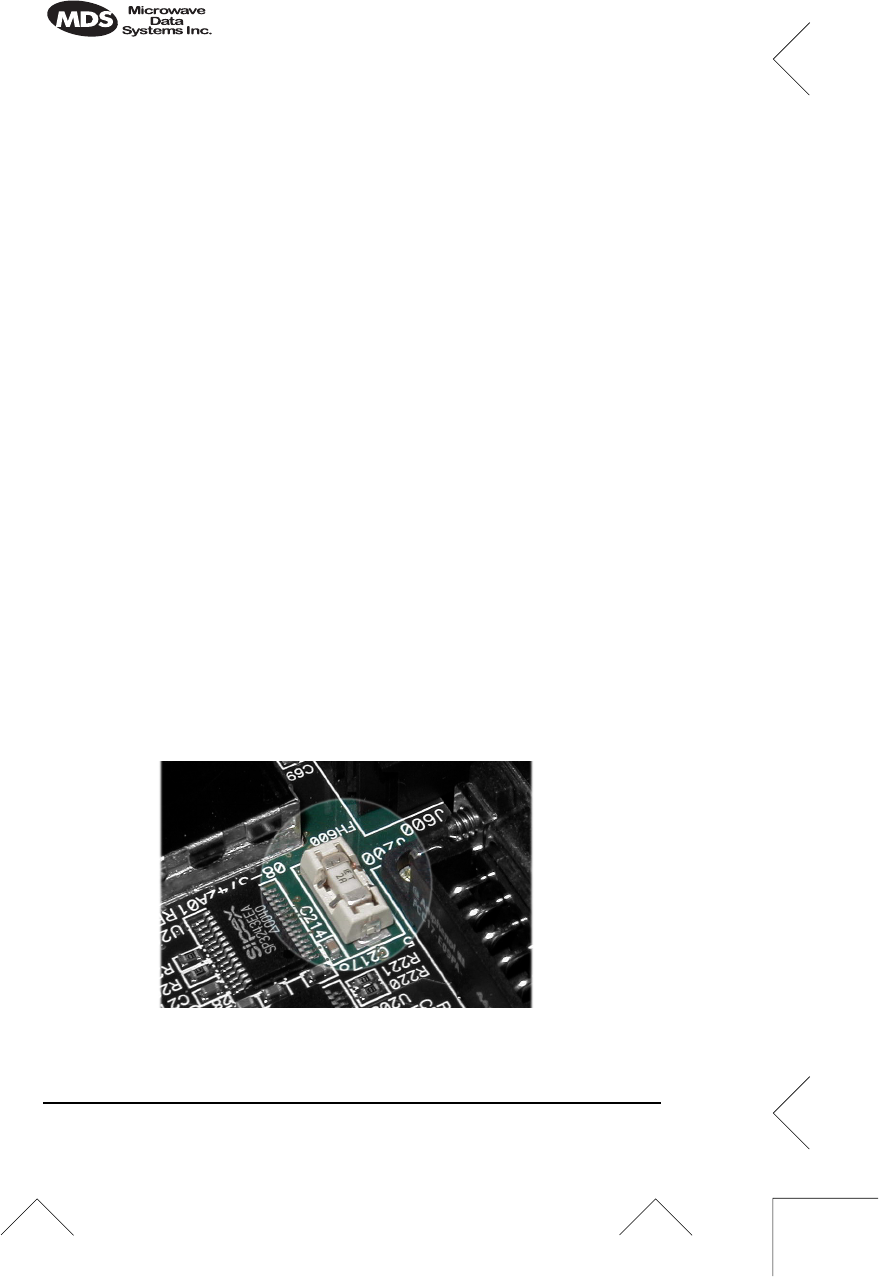
FUSE REPLACEMENT PROCEDURE
The iNET unit is protected by an internal fuse. The fuse will be blown
by a reverse polarity of the primary DC power, an over-voltage tran-
sient or an internal failure. The fuse should not be replaced until you
are certain you are in a safe environment
1. Remove the iNET unit from service.
2. Disconnect the primary power source and all other connections to
the unit.
3. Place the iNET unit on its back and remove the four Phillips
screws at the corners of the bottom cover.
4. Carefully separate the top and bottom covers. There is a flat ribbon
cable between the top cover’s LEDs and the unit motherboard.
You do not need to disconnect the ribbon cable.
5. Locate the fuse and fuse holder between the COM1 port and the
power connector. Figure 2 is a photograph of the fuse assembly.
6. Loosen the fuse from the holder using a very small screwdriver.
Use a small pair of needle-nose pliers to pull the fuse straight up
and remove it.
7. Install a new fuse by reversing the process.
Littelfuse P/N: 0454002; 452 Series, 2 Amp SMF Slo-Blo
(MDS P/N: 29-1784A03)
8. Replace the covers, interface cables and check the iNET unit for
proper operation.
Invisible place holder
Figure 2. Fuse Location

MDS 05-2873A01, Rev. A MDS iNET 900 Installation Guide 17
INET SPECIFICATIONS
GENERAL
Temperature Range: –30°C to +70°C (–22° F to 158° F)
Humidity: 95% at +40°C (104° F); non-condensing
Primary Power: 10.5–30 Vdc (13.8 Vdc Nominal)
External Power Supply Options: 48 Vdc; 110–120/210–220 Vac
Supply Current (typical): (@1 Watt RF Output)
Transmit: 500 mA @ 13.8 Vdc
Size (Excluding mtg. hardware): 1.5" x 6" x 4" (H x W x D)
3.8 x 15.2 x 10.2 cm
Weight: 0.9 kg / 2 lb
Case: Cast Aluminum
Shock and Vibration: Meets MIL STD 202F, 810E, 202D
RADIO CHARACTERISTICS
GENERAL:
Frequency Range: 902–928 MHz ISM Band
Mode: Freq. Hopping Spread-Spectrum (FHSS)
TRANSMITTER:
Power Output
(at antenna connector): 0.1 to 1.0 watt (+20 dBm to +30 dBm)
Increments of 1.0 dB, set by user
Duty Cycle: Continuous
Output Impedance: 50 Ohms
RECEIVER:
Type: Double conversion superheterodyne
Sensitivity: –92 dBm @ 512 kbps < 1x10⁻⁶ BER
–100 dBm @ 256 kbps < 1x10⁻⁶ BER
Time Required to Synchronize
with Access Point: < 1.4 minutes after boot (typical)

18 MDS iNET 900 Installation Guide MDS 05-2873A01, Rev. A
TECHNICAL ASSISTANCE
Technical assistance for MDS products is available from our Cus-
tomer Support Team during business hours (8:00 A.M.–5:30 P.M.
Eastern Time). When calling, please give the complete model number
of the radio, along with a description of the trouble symptom(s) that
you are experiencing. In many cases, problems can be resolved over
the telephone, without the need for returning the unit to the factory.
Telephone 1+ 585-242-8510 for product assistance or visit the tech-
nical support area of the Microwave Data Systems’ Web site at
www.microwavedata.com.
FACTORY SERVICE
If return of the equipment is necessary, please contact the MDS Cus-
tomer Support Team. You will be issued a Returned Material Autho-
rization (RMA) number. The RMA number will help expedite the
repair so that the equipment can be repaired and returned to you as
quickly as possible. Please be sure to include the RMA number on the
outside of the shipping box, and on any correspondence relating to the
repair. No equipment will be accepted for repair without an RMA
number.
A statement should accompany the radio describing, in detail, the
trouble symptom(s), and a description of any associated equipment
normally connected to the radio. It is also important to include the
name and telephone number of a person in your organization who can
be contacted if additional information is required.
The radio must be properly packed for return to the factory. The orig-
inal shipping container and packaging materials should be used when-
ever possible. All factory returns should be addressed to:
When repairs have been completed, the equipment will be returned to
you by the same shipping method used to send it to the factory. Please
specify if you wish to make different shipping arrangements.
Microwave Data Systems Inc.
Customer Service Department
(RMA No. XXXX)
175 Science Parkway
Rochester, NY 14620 USA
MDS 05-2873A01, Rev. A MDS iNET 900 Installation Guide 19
LAN COM1 COM2 PWR LINK
20 MDS iNET 900 Installation Guide MDS 05-2873A01, Rev. A
LAN COM1 COM2 PWR LINK