GE MDS DS-ROR220 MDS ROR220 DATA TRANSCEIVER User Manual users manual
GE MDS LLC MDS ROR220 DATA TRANSCEIVER users manual
UserManual.wiki
>
GE MDS
>
DS-ROR220 User Manual
>
users manual
Contents
1.
users manual
2.
Revised Users Manual
3.
Manual
users manual
Navigation menu
Upload a User Manual
Namespaces
Wiki Guide
HTML
PDF
Info
Views
User Manual
Discussion / Help
Navigation

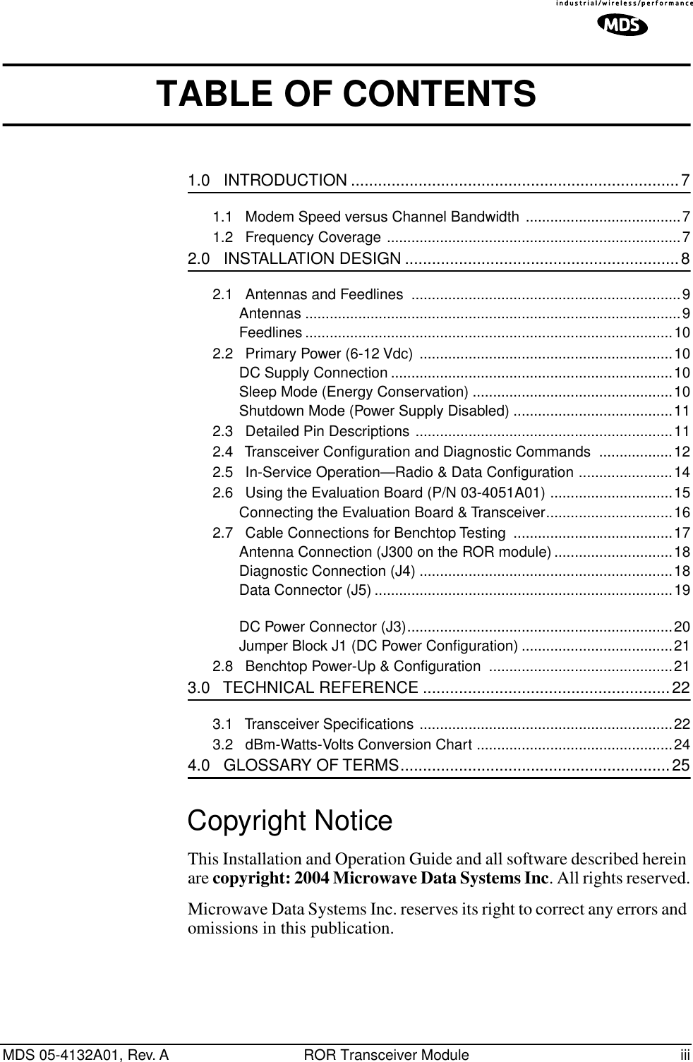
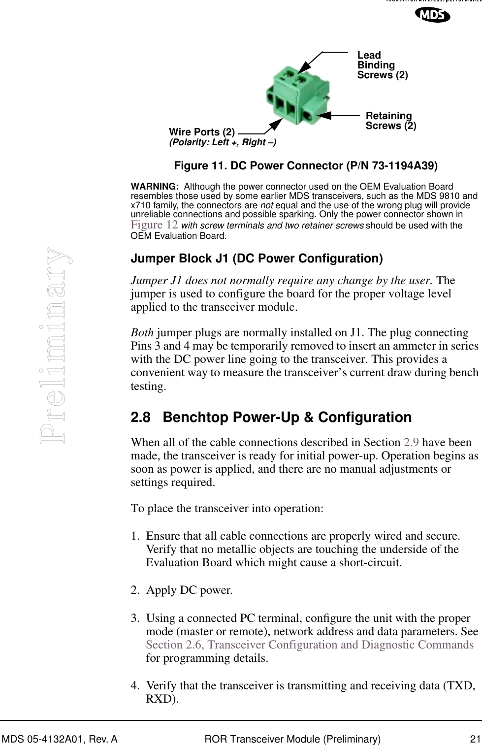
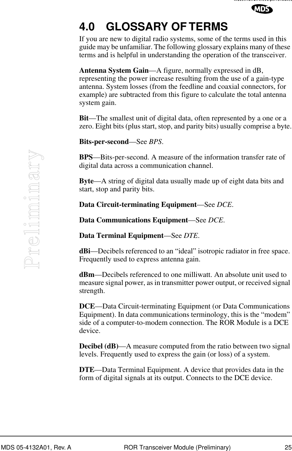
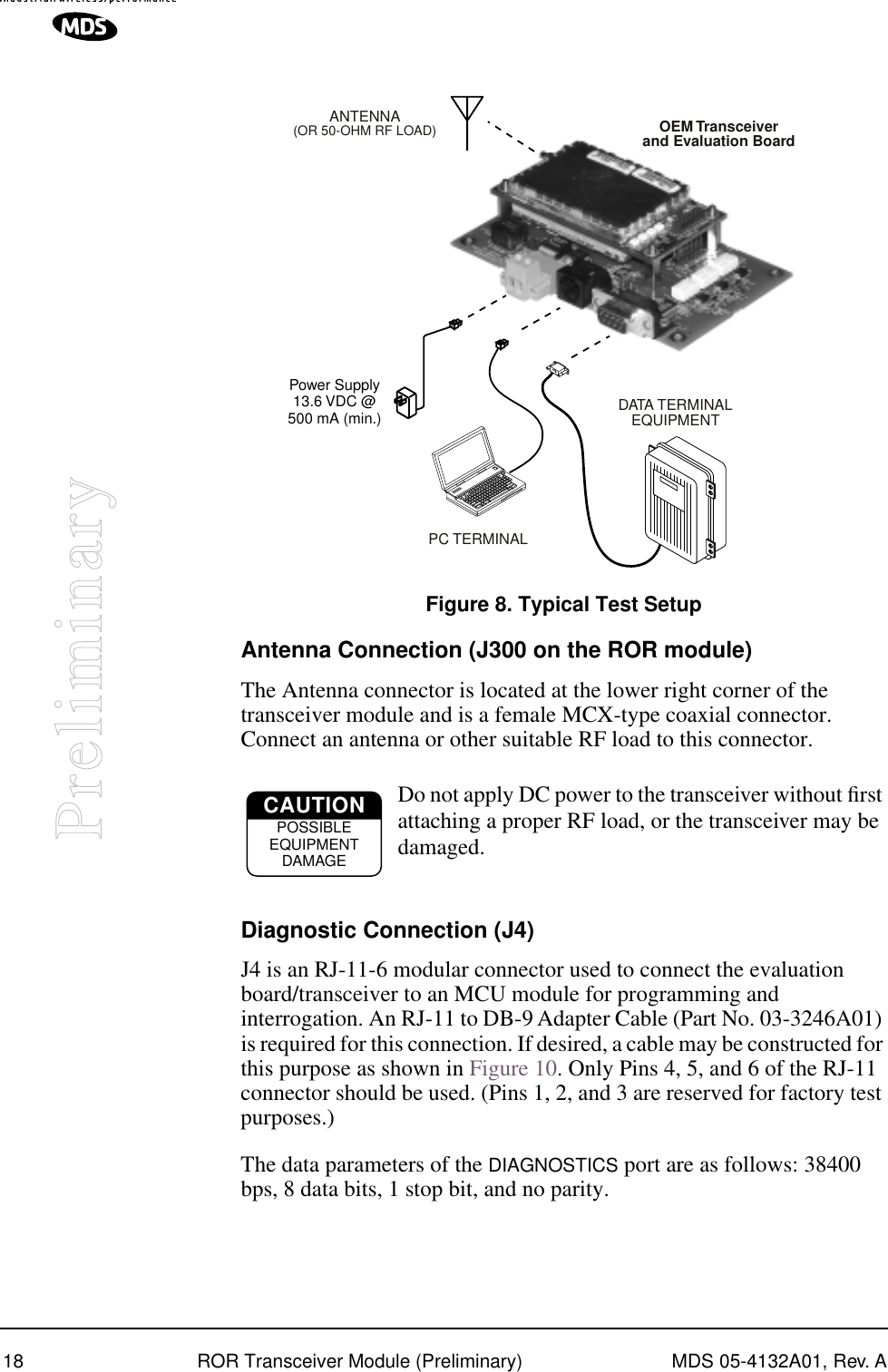
![MDS 05-4132A01, Rev. A ROR Transceiver Module (Preliminary) 11 Preliminary communication with other stations is needed. All radio and microprocessor activity is disabled when the radio is in Sleep Mode. When the ground is removed from Pin 6, the radio is ready to operate within 75 milliseconds. Shutdown Mode (Power Supply Disabled) The Shutdown Mode completely turns off the ROR Module’s power supply. It is asserted by placing a ground on Pin 8 of the DATA INTERFACE connector. With this pin grounded, all radio functions cease. 2.3 Detailed Pin Descriptions Table 3 provides detailed pin functions for the transceiver’s 16-pin header connector shown in Figure 6. Figure 5 . 16-pin Header Connector (J500) on Transceiver Module Table 2. Transceiver Data/Power Connector Pinouts (Payload data TTL; Diagnostic data TTL) Pin No. Input/Output SignalType Name/Description 1IN -- Ground— Connects to ground (negative supply potential).2 OUT TTL, 3 Vdc Diagnostic TXD— Supplies received diagnos-tic/administrative data to the connected device.3 OUT TTL, 3 Vdc Alarm condition— A low indicates normal opera-tion. A high indicates an alarm. (See ASENSE [HI/LO] command for more information.)4 IN TTL, 3 Vdc Diagnostic RXD—Accepts diagnostic/adminis-trative data from the connected device.5 IN -- FCC 6-12 Vdc version: DC Input (6-12 Vdc)— Supply Source must be capable of furnishing at least 7.5 watts.Non-FCC 3 Vdc version: Do not connect6 IN TTL, 3 Vdc Sleep Mode Input—A ground on this pin turns off most circuits in a remote radio. This allows for greatly reduced power consumption, yet pre-serves the radio’s ability to be brought quickly back on line. See Sleep Mode (Energy Conservation) on Page 12 for details.7 OUT TTL, 3 Vdc Reserved—Do not connect.8 IN TTL, 3 Vdc Power Supply Shutdown Control—A ground on this pin causes the OEM module’s power supply to shut down.116253487691514 1312 1110](https://usermanual.wiki/GE-MDS/DS-ROR220.users-manual/User-Guide-403487-Page-11.png)
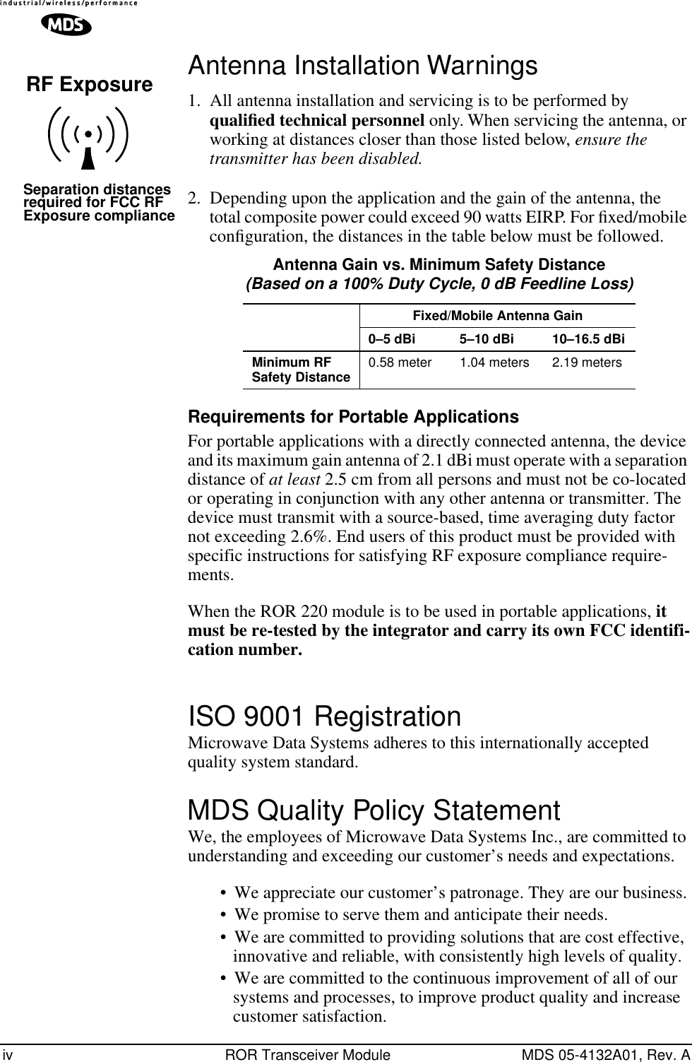
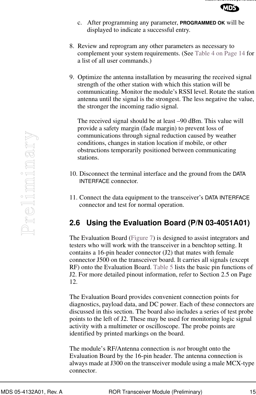
![12 ROR Transceiver Module (Preliminary) MDS 05-4132A01, Rev. APreliminarySome pins on the DATA INTERFACE connector are used for factory testing. Use only the required pins for the application. Damage may result if improper connections are made.2.4 Transceiver Configuration and Diagnostic CommandsThe transceiver’s configuration and diagnostics are performed through the radio’s DATA INTERFACE connector through a terminal interface—either a personal computer or dedicated data terminal. An EIA/RS-232 to TTL converter circuit may be required depending on your installation design. Configuration and diagnostic activities may be performed with the module removed from the user equipment or as an installed module in your design.If you choose to setup the module before its final installation, you may find it convenient to use the OEM Evaluation Board. (See Using the Evaluation Board (P/N 03-4051A01) on Page 16 for more detail.)Table 4 lists each command entry and a brief description of its purpose. Programmable information is shown in brackets [ ] following the command name.9 -- -- Non-FCC 3 Vdc version: DC Input (Regulated 3.3 Vdc)—Supply Source must be capable of fur-nishing at least 7.5 watts.FCC 6-12 Vdc version: Do not connect10 IN TTL, 3 Vdc Transmitted Data (TXD)—Accepts payload data from the connected device.11 IN -- FCC 6-12 Vdc version: DC Input (6-12 Vdc)— Supply Source must be capable of furnishing at least 7.5 watts.Non-FCC 3 Vdc version: Do not connect12 IN TTL, 3 Vdc Reserved—Do not connect.13 -- -- Reserved—Do not connect.14 OUT TTL, 3 Vdc Received Data (RXD)—Supplies received pay-load data to the connected device.15 IN -- Ground—Connects to ground (negative supply potential).16 OUT TTL, 3 Vdc Reserved—Do not connect.Table 2. Transceiver Data/Power Connector Pinouts(Payload data TTL; Diagnostic data TTL) (Continued)CAUTIONUSE ONLY REQUIRED PINS](https://usermanual.wiki/GE-MDS/DS-ROR220.users-manual/User-Guide-403487-Page-12.png)
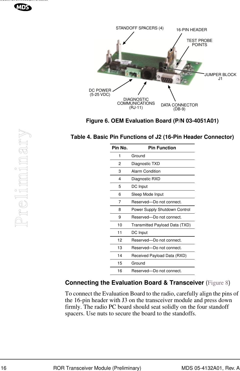
![MDS 05-4132A01, Rev. A ROR Transceiver Module (Preliminary) 13PreliminaryTo enter a command, type the command, followed by an keystroke. For programming commands, the command is followed by and the appropriate information or values, then . Table 3. Command Summary Command FunctionDKEY Unkey Transmitter Test CarrierKEY Transmitter Carrier Key• Test command for technicians to key the radio with an unmodulated carrier.• Use DKEY command to cease transmissionNOTES: • Use only for test purposes.• No time-out timer on this function.MODEM MODEM—Data ConfigurationResponse indicates:Payload data rate (BAUD) + Gaussian Bandwidth x Data Rate (BT) + Channel Spacing (BW)For example: 9.6Kbps BT=.3 12.5 KHz.NOTE: Provides only a read-only display. The command cannot be used to change the settings. PWR [x] RF Power Output LevelOptions: H = High Power (2 Watts)L = Low Power (0.5 Watts)RSSI Received Signal Strength Indictor• Displays the current received RF signal level• One measurement per request by command• Reading is accurate to within 3 dB from –100 dBm to –60 dBmNOTE: A continuous RSSI signal is available during receive state on the DATA INTERFACE connector (J500).SREV [xxx] Software Revision of installed firmwareSER Serial Number of the moduleRX [xxx.xxxxx] Receive RF Frequency• The frequency must be within the operating range for the unit. • Up to 5 digits can be entered after the decimal point. Trailing zeros are not required. • Frequencies can be in either 5 or 6.25 kHz increments.TX [xxx.xxxxx] Transmit RF Frequency• The frequency must be within the operating range for the unit. • Up to 5 digits can be entered after the decimal point. Trailing zeros are not required. • Frequencies can be in either 5 or 6.25 kHz increments.ENTERSPACE ENTER](https://usermanual.wiki/GE-MDS/DS-ROR220.users-manual/User-Guide-403487-Page-13.png)
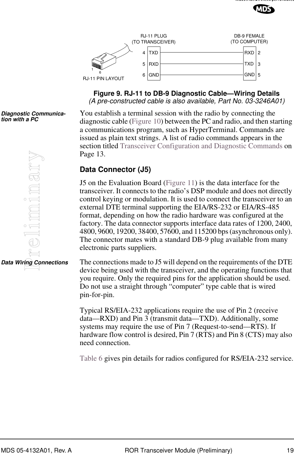
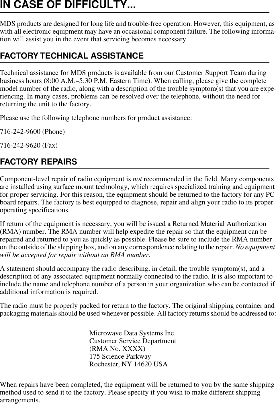
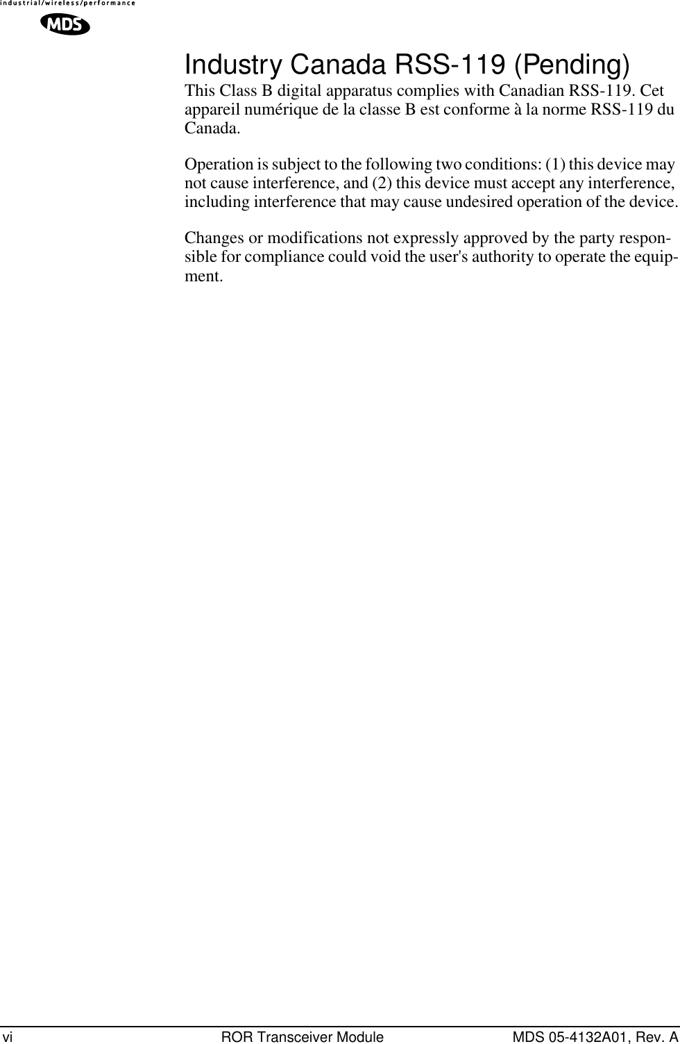
![20 ROR Transceiver Module (Preliminary) MDS 05-4132A01, Rev. APreliminaryNOTE: Radios equipped with a payload TTL interface are presented as RS-232 mode from the Evaluation Board.Pin Descriptions—RS/EIA-232 Mode Table 6 lists the DATA connector pin functions for radios configured to operate in RS/EIA-232 mode.DC Power Connector (J3)This connector accepts operating power for the transceiver. A wall-style AC adapter (Part No. 01-3862A02) is recommended for this service.DC connection is made with a 2-pin polarized plug, MDS Part No. 73-1194A39. Be sure to observe proper polarity. The left terminal is positive (+) and the right is negative (-). (See Figure 12).The transceiver must be used only with negative-ground systems. Make certain that the polarity of the power source is correct.Figure 10. DATA Connector (DB-9F)As viewed from outside the device5961Table 5. J5 DATA Connector Pinouts—RS/EIA-232 PinNumber Input/Output Pin Description1 -- Reserved—Do not connect.2 OUT Received Data (RXD)—Supplies received payload data to the connected device.3IN Transmitted Data (TXD)—Accepts payload data from the connected device.4IN Sleep Mode Input—A ground on this pin turns off most cir-cuits in a remote radio. This allows for greatly reduced pow-er consumption, yet preserves the radio’s ability to be brought quickly back on line. See Sleep Mode (Ener-gy Conservation) on Page 12 for details.5IN Ground—Connects to ground (negative supply potential).6 OUT Alarm condition—A low indicates normal operation. A high indicates an alarm. (See ASENSE [HI/LO] command for more information.)7 -- Reserved—Do not connect.8 --- Reserved—Do not connect.9 -- Reserved—Do not connect.CAUTIONPOSSIBLEEQUIPMENTDAMAGE](https://usermanual.wiki/GE-MDS/DS-ROR220.users-manual/User-Guide-403487-Page-20.png)