GE MDS DS-ROR220 MDS ROR220 DATA TRANSCEIVER User Manual users manual
GE MDS LLC MDS ROR220 DATA TRANSCEIVER users manual
GE MDS >
Contents
- 1. users manual
- 2. Revised Users Manual
- 3. Manual
users manual
Integration Guide
217-222 MHz Licensed OEM
Transceiver
ROR Module
Microwave Data Systems Inc.
MDS 05-4132A01, Rev. A
MARCH 2004
(PRELIMINARY)

MDS 05-4132A01, Rev. A ROR Transceiver Module iii
TABLE OF CONTENTS
1.0 INTRODUCTION .........................................................................7
1.1 Modem Speed versus Channel Bandwidth ......................................7
1.2 Frequency Coverage ........................................................................7
2.0 INSTALLATION DESIGN .............................................................8
2.1 Antennas and Feedlines ..................................................................9
Antennas ............................................................................................9
Feedlines ..........................................................................................10
2.2 Primary Power (6-12 Vdc) ..............................................................10
DC Supply Connection .....................................................................10
Sleep Mode (Energy Conservation) .................................................10
Shutdown Mode (Power Supply Disabled) .......................................11
2.3 Detailed Pin Descriptions ...............................................................11
2.4 Transceiver Configuration and Diagnostic Commands ..................12
2.5 In-Service Operation—Radio & Data Configuration .......................14
2.6 Using the Evaluation Board (P/N 03-4051A01) ..............................15
Connecting the Evaluation Board & Transceiver...............................16
2.7 Cable Connections for Benchtop Testing .......................................17
Antenna Connection (J300 on the ROR module).............................18
Diagnostic Connection (J4) ..............................................................18
Data Connector (J5) .........................................................................19
DC Power Connector (J3).................................................................20
Jumper Block J1 (DC Power Configuration) .....................................21
2.8 Benchtop Power-Up & Configuration .............................................21
3.0 TECHNICAL REFERENCE .......................................................22
3.1 Transceiver Specifications ..............................................................22
3.2 dBm-Watts-Volts Conversion Chart ................................................24
4.0 GLOSSARY OF TERMS............................................................25
Copyright Notice
This Installation and Operation Guide and all software described herein
are
copyright: 2004 Microwave Data Systems Inc
. All rights reserved.
Microwave Data Systems Inc. reserves its right to correct any errors and
omissions in this publication.

iv ROR Transceiver Module MDS 05-4132A01, Rev. A
Antenna Installation Warnings
1. All antenna installation and servicing is to be performed by
qualified technical personnel
only. When servicing the antenna, or
working at distances closer than those listed below,
ensure the
transmitter has been disabled.
2. Depending upon the application and the gain of the antenna, the
total composite power could exceed 90 watts EIRP. For fixed/mobile
configuration, the distances in the table below must be followed.
Requirements for Portable Applications
For portable applications with a directly connected antenna, the device
and its maximum gain antenna of 2.1 dBi must operate with a separation
distance of
at least
2.5 cm from all persons and must not be co-located
or operating in conjunction with any other antenna or transmitter. The
device must transmit with a source-based, time averaging duty factor
not exceeding 2.6%. End users of this product must be provided with
specific instructions for satisfying RF exposure compliance require-
ments.
When the ROR 220 module is to be used in portable applications,
it
must be re-tested by the integrator and carry its own FCC identifi-
cation number.
ISO 9001 Registration
Microwave Data Systems adheres to this internationally accepted
quality system standard.
MDS Quality Policy Statement
We, the employees of Microwave Data Systems Inc., are committed to
understanding and exceeding our customer’s needs and expectations.
• We appreciate our customer’s patronage. They are our business.
• We promise to serve them and anticipate their needs.
• We are committed to providing solutions that are cost effective,
innovative and reliable, with consistently high levels of quality.
• We are committed to the continuous improvement of all of our
systems and processes, to improve product quality and increase
customer satisfaction.
RF Exposure
Separation distances
required for FCC RF
Exposure compliance
Antenna Gain vs. Minimum Safety Distance
(Based on a 100% Duty Cycle, 0 dB Feedline Loss)
Fixed/Mobile Antenna Gain
0–5 dBi 5–10 dBi 10–16.5 dBi
Minimum RF
Safety Distance
0.58 meter 1.04 meters 2.19 meters

MDS 05-4132A01, Rev. A ROR Transceiver Module v
ESD Notice
To prevent malfunction or damage to this product, which may be caused
by Electrostatic Discharge (ESD), the radio should be properly
grounded at the time of installation. In addition, the installer or main-
tainer should follow proper ESD precautions, such as touching a bare
metal object to dissipate body charge, prior to touching components or
connecting/disconnecting cables.
Manual Revision and Accuracy
While every reasonable effort has been made to ensure the accuracy of
this manual, product improvements may result in minor differences
between the manual and the product shipped to you. If you have addi-
tional questions or need an exact specification for a product, please con-
tact our Customer Service Team using the information at the back of this
guide. In addition, manual updates can often be found on the MDS Web
site at www.microwavedata.com.
FCC Modular Approval Notice (Pending)
This device is offered as a Modular Transmitter in per FCC Part 90. It is
approved for use under the following conditions: (1) When this device
is placed inside an enclosure, a durable label must be affixed to the out-
side of that enclosure indicating the unit’s FCC ID Number:
E5MDS-ROR220.
(2) Changes or modifications not expressly approved by the party
responsible for compliance could void the user’s authority to operate the
equipment.
FCC Part 15 Notice (Pending)
This equipment has been tested and found to comply with the limits for
a Class B digital device, pursuant to Part 15 of the FCC Rules. These
limits are designed to provide reasonable protection against harmful
interference in a residential installation. This equipment generates, uses,
and can radiate radio frequency energy and, if not installed and used in
accordance with the instructions, may cause harmful interference to
radio communications. However, there is no guarantee that interference
will not occur in a particular installation. If this equipment does cause
harmful interference to radio or television reception, which can be deter-
mined by turning the equipment off and on, the user is encouraged to try
and correct the interference by one or more of the following measures:
• Reorient or locate the receiving antenna.
• Increase the separation between the equipment and receiver.
• Connect the equipment into an outlet on a circuit different from
that to which the receiver is connected.
• Consult the dealer or an experienced radio/TV technician for
help.

vi ROR Transceiver Module MDS 05-4132A01, Rev. A
Industry Canada RSS-119 (Pending)
This Class B digital apparatus complies with Canadian RSS-119. Cet
appareil numérique de la classe B est conforme à la norme RSS-119 du
Canada.
Operation is subject to the following two conditions: (1) this device may
not cause interference, and (2) this device must accept any interference,
including interference that may cause undesired operation of the device.
Changes or modifications not expressly approved by the party respon-
sible for compliance could void the user's authority to operate the equip-
ment.
MDS 05-4132A01, Rev. A ROR Transceiver Module (Preliminary) 7
Preliminary
1.0 INTRODUCTION
This guide presents installation and operating instructions for the ROR
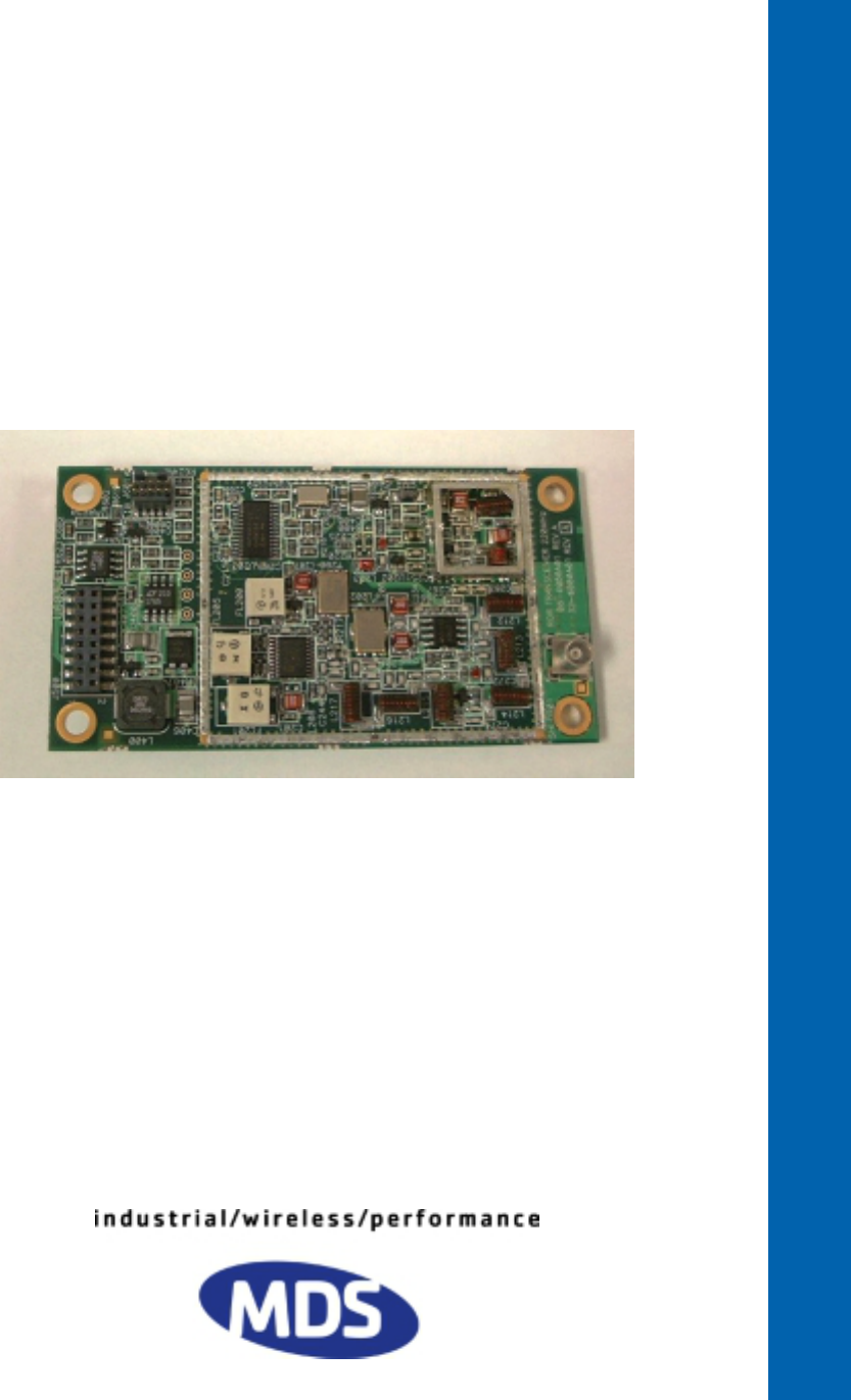
transceiver module. The unit is a compact, modular board intended for
integration inside customer-designed equipment.
The module (Figure 1) is a wireless data transceiver designed to operate
in an industrial environment. It employs two microprocessors—one for
Digital Signal Processing (DSP) control of the unit’s data port, and
another for control of modulation functions at the diagnostic port. The
module employs Gaussian-mean shift keying (GMSK) modulation.
These features provide highly reliable communications, even under
adverse conditions.
Invisible place holder
Figure 1. ROR Transceiver Module
(Module shown with shield cover removed)
1.1 Modem Speed versus Channel Bandwidth
The module is factory configured for an over-the-air data baud rate
(
BAUD
) of 9600 bps, Gaussian filtering (
BT=.3
), and a channel bandwidth
(
BW
) of 12.5 kHz. This configuration may be verified by use of the
MODEM
command. These settings are independent of any other
user-controllable parameter.
1.2 Frequency Coverage
The ROR module is designed for operation in the 217-222 MHz
frequency band. Any combination of transmitter and receiver operating
frequencies can be programmed, including a simplex (TX = RX) pair.
8 ROR Transceiver Module (Preliminary) MDS 05-4132A01, Rev. A
Preliminary
2.0 INSTALLATION DESIGN
The module is designed to be an integral part of another electronic
device or system. It must be provided with adequate and stable primary
power, a complementary data interface and a suitable antenna system.
An antenna is the only external device that is needed for operation.
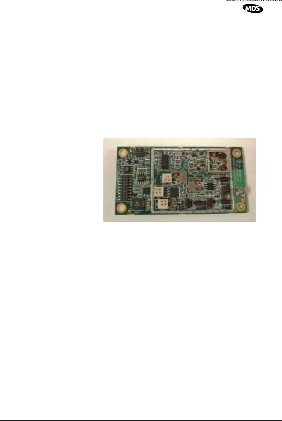
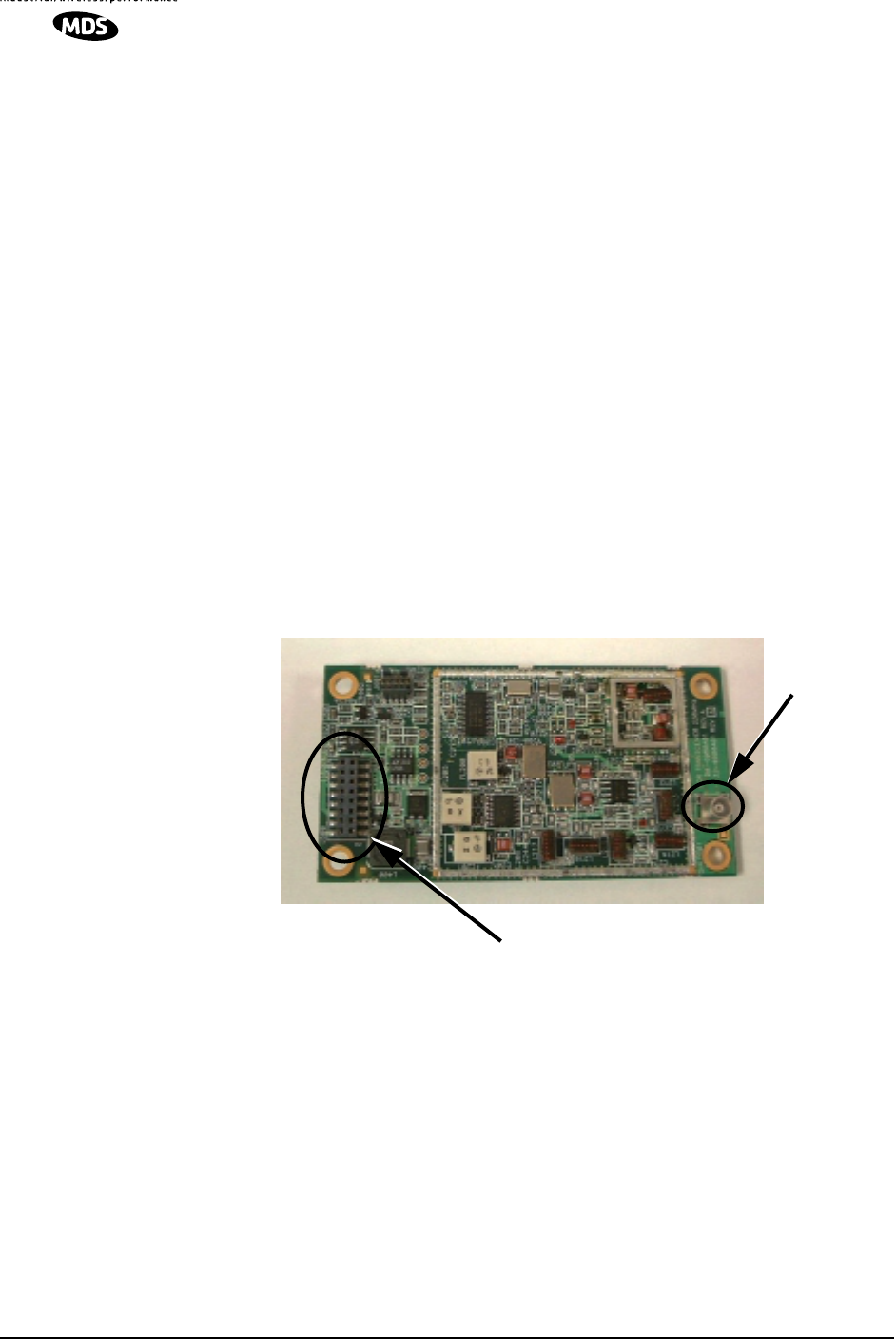
The module has just two connectors—one for data/power, and another
for the antenna connection. Figure 2 shows the location of these
connectors.
The data/power connector (J500) is a 16-pin dual-row header connector
that mates with a Samtec TW Series, Part No. ASP 103812-01. This
matching connector is provided on the OEM Test/Evaluation board,
described later in this manual. Data signals and DC power are applied to
the module through this board or another device to which the radio is
attached.
The Antenna/RF Output connector (J300) is located at the lower right
side of the module, and is a female MCX-type coaxial connector. A
suitable RF load or antenna may be connected to this connector.
Invisible place holder
Figure 2. Connections to the Transceiver Module
(Module shown with shield cover removed)
In its deliverable form, the module has all of its electronic circuitry
enclosed in RF shields to minimize interaction with nearby electronic
products. Careful selection and/or routing of the unit’s antenna feedline
line may be required to minimize RFI to other electronic devices
mounted near the module. The module can be set to produce either 0.5
watt, or 2 watts of RF output using a connected terminal (requires use of
PWR
command).
ANTENNA
DATA & POWER CONNECTOR (J500)
CONNECTOR
(J300)
MDS 05-4132A01, Rev. A ROR Transceiver Module (Preliminary) 9
Preliminary
For optimal communication range and reliability, this unit must be
provided with a good antenna system. A secondary benefit to an
effective antenna system is the ability to run the system at the lowest
possible power level, minimize primary power consumption, and reduce
the chance for interference.
The data interface for the module supports TTL-type signaling. Use
only the required pins for the application.
Refer to the complete list of
pin functions in Table 5 on Page 17.
2.1 Antennas and Feedlines
Antennas
The module can be used with a variety of antennas, ranging from a
directly-connected flexible type, to a highly directional array. The exact
style depends on the physical size and layout of the radio system.
Suitable antennas are available from several manufacturers, including
Microwave Data Systems.
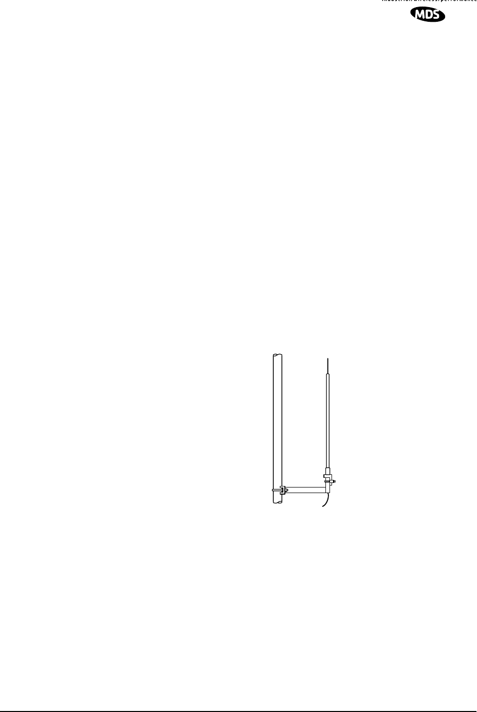
At master stations, omni-directional antennas (Figure 4) are typically
used to provide equal coverage to all remote sites in the network.
Invisible place holder
Figure 3. Typical Omni-directional Antenna for Master Stations
(Shown mounted to mast)
At remote sites, a directional Yagi (Figure 5) or corner reflector antenna
is generally recommended to minimize interference to and from other
users.

10 ROR Transceiver Module (Preliminary) MDS 05-4132A01, Rev. A
Preliminary
Invisible place holder
Figure 4. Typical Yagi Antenna for Remote Sites
Feedlines
The selection of a proper antenna feedline is very important. Poor
quality cables should be avoided as they can result in power losses that
may reduce the range and reliability of the radio system.
Table 2 shows the losses that occur when using various lengths and
types of cable at 200 MHz. Regardless of the type of cable used, it
should be kept as short as possible to minimize signal loss.
2.2 Primary Power (6-12 Vdc)
DC Supply Connection
The transceiver can be operated from any well-filtered 6-12 Vdc power
source through the
DATA INTERFACE
connector. The power supply must
be capable of providing at least 1.5 Amperes and provide current
limiting even if you intend to operate the radio at low power (0.5 Watts).
NOTE: The radio is designed for use in
negative
ground systems only.
There is no fuse or reverse polarity protection provided on the
module’s PCB assembly.
Sleep Mode (Energy Conservation)
In some installations, such as at solar-powered sites, it may be necessary
to keep the transceiver’s power consumption to an absolute minimum.
This can be accomplished by configuring the host device to ground Pin
6 on the
DATA INTERFACE
connector, which powers down the radio until
Table 1. Length vs. Loss in Coaxial Cables at 200 MHz
Cable Type 10 Feet
(3.05 Meters)
50 Feet
(15.24 Meters)
100 Feet
(30.48 Meters)
500 Feet
(152.4 Meters)
RG-8A/U 0.32dB 1.6 dB 3.2 dB 16 dB
1/2 inch HELIAX
0.10 dB 0.49 dB 0.98 dB 4.9 dB
7/8 inch HELIAX
0.05 dB 0.27 dB 0.54 dB 2.7 dB
1-1/4 inch HELIAX
0.04 dB 0.20 dB 0.40 dB 2.0 dB
1-5/8 inch HELIAX
0.03 dB 0.17 dB 0.33 dB 1.65 dB
CAUTION
POSSIBLE
EQUIPMENT
DAMAGE
MDS 05-4132A01, Rev. A ROR Transceiver Module (Preliminary) 11
Preliminary
communication with other stations is needed. All radio and
microprocessor activity is disabled when the radio is in Sleep Mode.
When the ground is removed from Pin 6, the radio is ready to operate
within 75 milliseconds.
Shutdown Mode (Power Supply Disabled)
The Shutdown Mode completely turns off the ROR Module’s power
supply. It is asserted by placing a ground on Pin 8 of the
DATA
INTERFACE
connector. With this pin grounded, all radio functions cease.
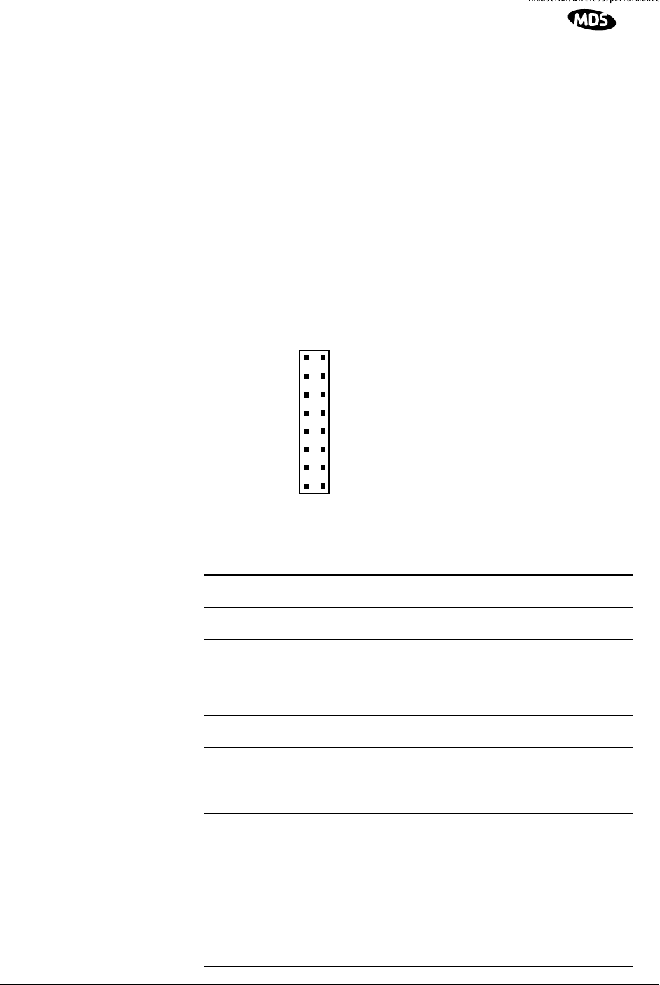
2.3 Detailed Pin Descriptions
Table 3 provides detailed pin functions for the transceiver’s 16-pin
header connector shown in Figure 6.
Figure 5
.
16-pin Header
Connector (J500) on
Transceiver Module
Table 2. Transceiver Data/Power Connector Pinouts
(Payload data TTL; Diagnostic data TTL)
Pin No. Input/
Output Signal
Type Name/Description
1IN --
Ground—
Connects to ground (negative supply
potential).
2 OUT TTL, 3 Vdc
Diagnostic TXD—
Supplies received diagnos-
tic/administrative data to the connected device.
3 OUT TTL, 3 Vdc
Alarm condition—
A low indicates normal opera-
tion. A high indicates an alarm. (See ASENSE
[HI/LO] command for more information.)
4 IN TTL, 3 Vdc
Diagnostic RXD—Accepts diagnostic/adminis-
trative data from the connected device.
5 IN -- FCC 6-12 Vdc version: DC Input (6-12 Vdc)—
Supply Source must be capable of furnishing at
least 7.5 watts.
Non-FCC 3 Vdc version: Do not connect
6 IN TTL, 3 Vdc Sleep Mode Input—A ground on this pin turns off
most circuits in a remote radio. This allows for
greatly reduced power consumption, yet pre-
serves the radio’s ability to be brought quickly
back on line. See Sleep Mode (Energy
Conservation) on Page 12 for details.
7 OUT TTL, 3 Vdc Reserved—Do not connect.
8 IN TTL, 3 Vdc Power Supply Shutdown Control—A ground on
this pin causes the OEM module’s power supply
to shut down.
1
16
2
5
34
87
6
9
15
14 13
12 11
10

12 ROR Transceiver Module (Preliminary) MDS 05-4132A01, Rev. A
Preliminary
Some pins on the DATA INTERFACE connector are used for factory
testing. Use only the required pins for the application. Damage may
result if improper connections are made.
2.4 Transceiver Configuration and Diagnostic
Commands
The transceiver’s configuration and diagnostics are performed through
the radio’s DATA INTERFACE connector through a terminal interface—
either a personal computer or dedicated data terminal. An EIA/RS-232
to TTL converter circuit may be required depending on your installation
design. Configuration and diagnostic activities may be performed with
the module removed from the user equipment or as an installed module
in your design.
If you choose to setup the module before its final installation, you may
find it convenient to use the OEM Evaluation Board. (See Using the
Evaluation Board (P/N 03-4051A01) on Page 16 for more detail.)
Table 4 lists each command entry and a brief description of its purpose.
Programmable information is shown in brackets [ ] following the
command name.
9 -- -- Non-FCC 3 Vdc version: DC Input (Regulated
3.3 Vdc)—Supply Source must be capable of fur-
nishing at least 7.5 watts.
FCC 6-12 Vdc version: Do not connect
10 IN TTL, 3 Vdc Transmitted Data (TXD)—Accepts payload data
from the connected device.
11 IN -- FCC 6-12 Vdc version: DC Input (6-12 Vdc)—
Supply Source must be capable of furnishing at
least 7.5 watts.
Non-FCC 3 Vdc version: Do not connect
12 IN TTL, 3 Vdc Reserved—Do not connect.
13 -- -- Reserved—Do not connect.
14 OUT TTL, 3 Vdc Received Data (RXD)—Supplies received pay-
load data to the connected device.
15 IN -- Ground—Connects to ground (negative supply
potential).
16 OUT TTL, 3 Vdc Reserved—Do not connect.
Table 2. Transceiver Data/Power Connector Pinouts
(Payload data TTL; Diagnostic data TTL) (Continued)
CAUTION
USE ONLY
REQUIRED PINS

MDS 05-4132A01, Rev. A ROR Transceiver Module (Preliminary) 13
Preliminary
To enter a command, type the command, followed by an
keystroke. For programming commands, the command is followed by
and the appropriate information or values, then .
Table 3. Command Summary
Command Function
DKEY Unkey Transmitter Test Carrier
KEY Transmitter Carrier Key
• Test command for technicians to key the radio with an
unmodulated carrier.
• Use DKEY command to cease transmission
NOTES:
• Use only for test purposes.
• No time-out timer on this function.
MODEM MODEM—Data Configuration
Response indicates:
Payload data rate (BAUD)
+ Gaussian Bandwidth x Data Rate (BT)
+ Channel Spacing (BW)
For example: 9.6Kbps BT=.3 12.5 KHz.
NOTE: Provides only a read-only display. The command
cannot be used to change the settings.
PWR [x] RF Power Output Level
Options:
H = High Power (2 Watts)
L = Low Power (0.5 Watts)
RSSI Received Signal Strength Indictor
• Displays the current received RF signal level
• One measurement per request by command
• Reading is accurate to within 3 dB from –100 dBm to –60
dBm
NOTE: A continuous RSSI signal is available during receive
state on the DATA INTERFACE connector (J500).
SREV [xxx] Software Revision of installed firmware
SER Serial Number of the module
RX [xxx.xxxxx] Receive RF Frequency
• The frequency must be within the operating range for the
unit.
• Up to 5 digits can be entered after the decimal point.
Trailing zeros are not required.
• Frequencies can be in either 5 or 6.25 kHz increments.
TX [xxx.xxxxx] Transmit RF Frequency
• The frequency must be within the operating range for the
unit.
• Up to 5 digits can be entered after the decimal point.
Trailing zeros are not required.
• Frequencies can be in either 5 or 6.25 kHz increments.
ENTER
SPACE ENTER

14 ROR Transceiver Module (Preliminary) MDS 05-4132A01, Rev. A
Preliminary
2.5 In-Service Operation—Radio & Data
Configuration
Below are the basic steps for setting up of the transceiver once it is
installed in the host device. In many cases, these steps alone are
sufficient to complete the installation. This procedure assumes the
module has been installed in your system/product and suitable
connections have been provided for a terminal interface and antenna.
3. Install the antenna and antenna feedline for the station. Preset
directional antennas in the desired direction of transmission and
reception.
4. Connect a terminal (computer with emulations software) to the
module through the user’s product interface. (Asynchronous @
38400 bps w/8N1)
5. Enable the configuration mode for the module. DIAGNOSTICS OPEN
will appear on the terminal screen terminal once diagnostics
communication with the radio is established.
6. Review the existing configuration parameters through a series of
terminal commands.
•MODEM—Data Configuration
Response indicates:
Payload data rate (BAUD)
Gaussian Bandwidth x Data Rate (BT)
Channel Spacing (BW)
For example: 9.6Kbps BT=.3 12.5KHz.
•PWR—RF Power Output
Responses: H = 2 Watts, L = 0.5 Watts
7. Check and set the radio transmit and receive frequencies.
NOTE: The operating frequencies are typically not set at the factory.
Determine the transmit and receive frequencies to be used, and
follow the steps below to program them. The module must be
programmed for the frequencies for which you hold a valid
license.)
a. Set the transmit frequency with the TX xxx.xxxxx command.
Press after the command.
b. Set the receive frequency with the RX xxx.xxxxx command.
Press after the command.
ENTER
ENTER

MDS 05-4132A01, Rev. A ROR Transceiver Module (Preliminary) 15
Preliminary
c. After programming any parameter, PROGRAMMED OK will be
displayed to indicate a successful entry.
8. Review and reprogram any other parameters as necessary to
complement your system requirements. (See Table 4 on Page 14 for
a list of all user commands.)
9. Optimize the antenna installation by measuring the received signal
strength of the other station with which this station will be
communicating. Monitor the module’s RSSI level. Rotate the station
antenna until the signal is the strongest. The less negative the value,
the stronger the incoming radio signal.
The received signal should be at least –90 dBm. This value will
provide a safety margin (fade margin) to prevent loss of
communications through signal reduction caused by weather
conditions, changes in station location if mobile, or other
obstructions temporarily positioned between communicating
stations.
10. Disconnect the terminal interface and the ground from the DATA
INTERFACE connector.
11. Connect the data equipment to the transceiver’s DATA INTERFACE
connector and test for normal operation.
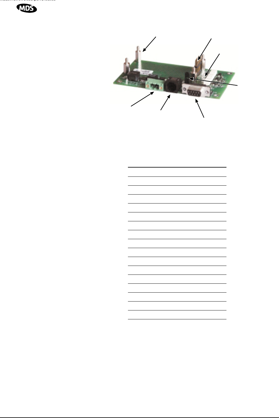
2.6 Using the Evaluation Board (P/N 03-4051A01)
The Evaluation Board (Figure 7) is designed to assist integrators and
testers who will work with the transceiver in a benchtop setting. It
contains a 16-pin header connector (J2) that mates with female
connector J500 on the transceiver board. It carries all signals (except
RF) onto the Evaluation Board. Table 5 lists the basic pin functions of
J2. For more detailed pinout information, refer to Section 2.5 on Page
12.
The Evaluation Board provides convenient connection points for
diagnostics, payload data, and DC power. Each of these connectors are
discussed in this section. The board also includes a series of test probe
points to the left of J2. These may be used for monitoring logic signal
activity with a multimeter or oscilloscope. The probe points are
identified by printed markings on the board.
The module’s RF/Antenna connection is not brought onto the
Evaluation Board by the 16-pin header. The antenna connection is
always made at J300 on the transceiver module using a male MCX-type
connector.
16 ROR Transceiver Module (Preliminary) MDS 05-4132A01, Rev. A
Preliminary
Figure 6. OEM Evaluation Board (P/N 03-4051A01)
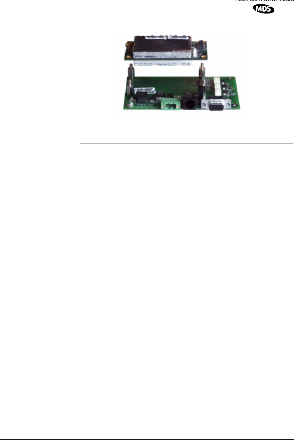
Connecting the Evaluation Board & Transceiver (Figure 8)
To connect the Evaluation Board to the radio, carefully align the pins of
the 16-pin header with J3 on the transceiver module and press down
firmly. The radio PC board should seat solidly on the four standoff
spacers. Use nuts to secure the board to the standoffs.
Table 4. Basic Pin Functions of J2 (16-Pin Header Connector)
Pin No. Pin Function
1 Ground
2 Diagnostic TXD
3 Alarm Condition
4 Diagnostic RXD
5 DC Input
6 Sleep Mode Input
7 Reserved—Do not connect.
8 Power Supply Shutdown Control
9 Reserved—Do not connect.
10 Transmitted Payload Data (TXD)
11 DC Input
12 Reserved—Do not connect.
13 Reserved—Do not connect.
14 Received Payload Data (RXD)
15 Ground
16 Reserved—Do not connect.
TEST PROBE
POINTS
DIAGNOSTIC
COMMUNICATIONS
(RJ-11) DATA CONNECTOR
(DB-9)
DC POWER
(5-25 VDC)
STANDOFF SPACERS (4) 16-PIN HEADER
JUMPER BLOCK
J1
MDS 05-4132A01, Rev. A ROR Transceiver Module (Preliminary) 17
Preliminary
Invisible place holder
Figure 7. Connecting the Evaluation Board and ROR Module
CAUTION: Take care to avoid short-circuiting the underside of the
Evaluation board. The bottom of the board is not insulated, and
contact with metallic objects on the work surface could cause
damage to the board or connected equipment.
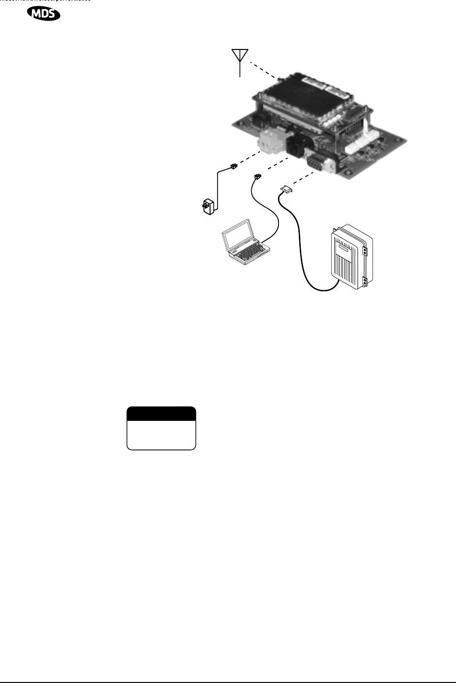
2.7 Cable Connections for Benchtop Testing
There are four basic requirements for operating the transceiver and
evaluation board in a benchtop environment. They are:
• Adequate and stable primary power
• A proper antenna system or RF load (50 Ohms)
• The correct interface wiring between the transceiver and the
connected DTE device
• A connected PC terminal to read/set transceiver parameters
Figure 9 shows a typical setup for bench testing an OEM Transceiver.
Two such setups will be required if you intend to establish over-the-air
communications with another transceiver.
18 ROR Transceiver Module (Preliminary) MDS 05-4132A01, Rev. A
Preliminary
Invisible place holder
Figure 8. Typical Test Setup
Antenna Connection (J300 on the ROR module)
The Antenna connector is located at the lower right corner of the
transceiver module and is a female MCX-type coaxial connector.
Connect an antenna or other suitable RF load to this connector.
Do not apply DC power to the transceiver without first
attaching a proper RF load, or the transceiver may be
damaged.
Diagnostic Connection (J4)
J4 is an RJ-11-6 modular connector used to connect the evaluation
board/transceiver to an MCU module for programming and
interrogation. An RJ-11 to DB-9 Adapter Cable (Part No. 03-3246A01)
is required for this connection. If desired, a cable may be constructed for
this purpose as shown in Figure 10. Only Pins 4, 5, and 6 of the RJ-11
connector should be used. (Pins 1, 2, and 3 are reserved for factory test
purposes.)
The data parameters of the DIAGNOSTICS port are as follows: 38400
bps, 8 data bits, 1 stop bit, and no parity.
OEM Transceiver
and Evaluation Board
ANTENNA
(OR 50-OHM RF LOAD)
PC TERMINAL
DATA TERMINAL
EQUIPMENT
Power Supply
13.6 VDC @
500 mA (min.)
CAUTION
POSSIBLE
EQUIPMENT
DAMAGE

MDS 05-4132A01, Rev. A ROR Transceiver Module (Preliminary) 19
Preliminary
Invisible place holder
Figure 9. RJ-11 to DB-9 Diagnostic Cable—Wiring Details
(A pre-constructed cable is also available, Part No. 03-3246A01)
Diagnostic Communica-
tion with a PC You establish a terminal session with the radio by connecting the
diagnostic cable (Figure 10) between the PC and radio, and then starting
a communications program, such as HyperTerminal. Commands are
issued as plain text strings. A list of radio commands appears in the
section titled Transceiver Configuration and Diagnostic Commands on
Page 13.
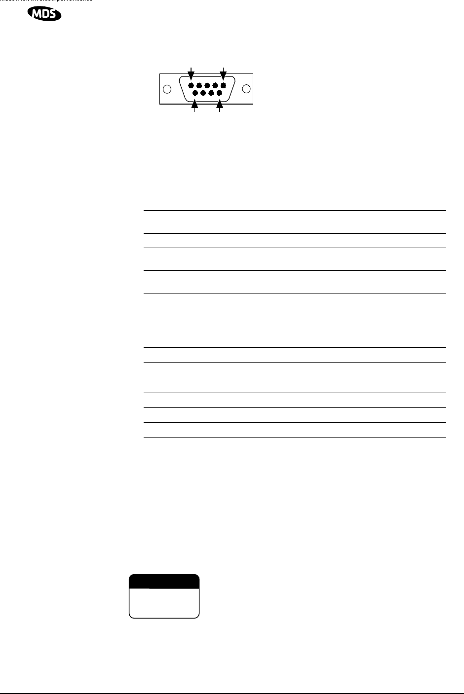
Data Connector (J5)
J5 on the Evaluation Board (Figure 11) is the data interface for the
transceiver. It connects to the radio’s DSP module and does not directly
control keying or modulation. It is used to connect the transceiver to an
external DTE terminal supporting the EIA/RS-232 or EIA/RS-485
format, depending on how the radio hardware was configured at the
factory. The data connector supports interface data rates of 1200, 2400,
4800, 9600, 19200, 38400, 57600, and 115200 bps (asynchronous only).
The connector mates with a standard DB-9 plug available from many
electronic parts suppliers.
Data Wiring Connections The connections made to J5 will depend on the requirements of the DTE
device being used with the transceiver, and the operating functions that
you require. Only the required pins for the application should be used.
Do not use a straight through “computer” type cable that is wired
pin-for-pin.
Typical RS/EIA-232 applications require the use of Pin 2 (receive
data—RXD) and Pin 3 (transmit data—TXD). Additionally, some
systems may require the use of Pin 7 (Request-to-send—RTS). If
hardware flow control is desired, Pin 7 (RTS) and Pin 8 (CTS) may also
need connection.
Table 6 gives pin details for radios configured for RS/EIA-232 service.
RXD
TXD
GND
2
3
5
DB-9 FEMALE
(TO COMPUTER)
TXD
RXD
GND
4
5
6
RJ-11 PLUG
(TO TRANSCEIVER)
RJ-11 PIN LAYOUT
16
20 ROR Transceiver Module (Preliminary) MDS 05-4132A01, Rev. A
Preliminary
NOTE: Radios equipped with
a payload TTL interface are
presented as RS-232 mode
from the Evaluation Board.
Pin Descriptions—
RS/EIA-232 Mode Table 6 lists the DATA connector pin functions for radios configured to operate in
RS/EIA-232 mode.
DC Power Connector (J3)
This connector accepts operating power for the transceiver. A wall-style
AC adapter (Part No. 01-3862A02) is recommended for this service.
DC connection is made with a 2-pin polarized plug, MDS Part No.
73-1194A39. Be sure to observe proper polarity. The left terminal is
positive (+) and the right is negative (-). (See Figure 12).
The transceiver must be used only with negative-ground systems.
Make certain that the polarity of the power source is correct.
Figure 10. DATA Connector (DB-9F)
As viewed from outside the device
5
96
1
Table 5. J5 DATA Connector Pinouts—RS/EIA-232
Pin
Number Input/
Output Pin Description
1 -- Reserved—Do not connect.
2 OUT Received Data (RXD)—Supplies received payload data to
the connected device.
3IN Transmitted Data (TXD)—Accepts payload data from the
connected device.
4IN Sleep Mode Input—A ground on this pin turns off most cir-
cuits in a remote radio. This allows for greatly reduced pow-
er consumption, yet preserves the radio’s ability to be
brought quickly back on line. See Sleep Mode (Ener-
gy Conservation) on Page 12 for details.
5IN Ground—Connects to ground (negative supply potential).
6 OUT Alarm condition—A low indicates normal operation. A high
indicates an alarm. (See ASENSE [HI/LO] command for
more information.)
7 -- Reserved—Do not connect.
8 --- Reserved—Do not connect.
9 -- Reserved—Do not connect.
CAUTION
POSSIBLE
EQUIPMENT
DAMAGE

MDS 05-4132A01, Rev. A ROR Transceiver Module (Preliminary) 21
Preliminary
Invisible place holder
Figure 11. DC Power Connector (P/N 73-1194A39)
WARNING: Although the power connector used on the OEM Evaluation Board
resembles those used by some earlier MDS transceivers, such as the MDS 9810 and
x710 family, the connectors are not equal and the use of the wrong plug will provide
unreliable connections and possible sparking. Only the power connector shown in
Figure 12 with screw terminals and two retainer screws should be used with the
OEM Evaluation Board.
Jumper Block J1 (DC Power Configuration)
Jumper J1 does not normally require any change by the user. The
jumper is used to configure the board for the proper voltage level
applied to the transceiver module.
Both jumper plugs are normally installed on J1. The plug connecting
Pins 3 and 4 may be temporarily removed to insert an ammeter in series
with the DC power line going to the transceiver. This provides a
convenient way to measure the transceiver’s current draw during bench
testing.
2.8 Benchtop Power-Up & Configuration
When all of the cable connections described in Section 2.9 have been
made, the transceiver is ready for initial power-up. Operation begins as
soon as power is applied, and there are no manual adjustments or
settings required.
To place the transceiver into operation:
1. Ensure that all cable connections are properly wired and secure.
Verify that no metallic objects are touching the underside of the
Evaluation Board which might cause a short-circuit.
2. Apply DC power.
3. Using a connected PC terminal, configure the unit with the proper
mode (master or remote), network address and data parameters. See
Section 2.6, Transceiver Configuration and Diagnostic Commands
for programming details.
4. Verify that the transceiver is transmitting and receiving data (TXD,
RXD).
Lead
Screws (2)
Binding
Wire Ports (2)
(Polarity: Left +, Right –)
Retaining
Screws (2)

22 ROR Transceiver Module (Preliminary) MDS 05-4132A01, Rev. A
Preliminary
3.0 TECHNICAL REFERENCE
3.1 Transceiver Specifications
RADIO TYPE
Synthesized, half duplex or simplex, 6.25 and 5.0 kHz channel spacing
ENVIRONMENTAL
Temperature Range: –30 to +60 degrees C
Humidity: 0 to 95% at 40 degrees C
Board Dimensions: 2.75″ W x 0.4″ H x 1.75″ D
7.0 cm W x 1.10 cm H x 4.4 cm D
Weight: x.x oz. (x.x kg)
Enclosure: None. PCB with digital/RF circuit shielding
TRANSMITTER
Frequency Range: 217-222 MHz
Frequency Increments: 6.25 and 5.0 kHz
Frequency Stability: 1.5 ppm, –30 to +60 degrees C
Channel Spacing: 6.25 and 5.0 kHz
Modulation Type: GMSK (Gaussian-mean Shift Keying) B.T.= .3
Carrier Power: 0.5 W, 2 W programmable
(+27 DBM, +33 dBm)
Duty Cycle: 50%
Output Impedance: 50 ohms
RF Connection: MCX coaxial connector
Spurious and Harmonics: –65 dBc
Transmitter Keying: On reception of data
Key-up Time: 2 ms
Data Rate Over-the-Air : 9600 bps
RECEIVER
Type: Double conversion superheterodyne
(45 MHz IF)
Frequency Range: 217-222 MHz
Frequency Increments: 6.25 and 5.0 kHz
Frequency Stability: 1.5 ppm, –30 to +60 degrees C
Spurious and Image Rejection: –70 dB
Sensitivity: 12 dB SINAD @ –119 dBm @ 9600 bps
Intermodulation Rejection: –70 dB minimum
Selectivity: 60 dB typical at adjacent channel (EIA)
Bandwidth: 12.5 kHz
DATA INTERFACE
Connector: 16 Pin dual header
Signaling: TTL
Data Rate—Over-the-air: 9600 bps
Data Rate—Diagnostics: 38400 bps asynchronous
Data Latency: < 20 ms typical

MDS 05-4132A01, Rev. A ROR Transceiver Module (Preliminary) 23
Preliminary
PRIMARY POWER
Voltage: 6-12 Vdc via Data Interface connector
RX Current at 10 Vdc (typical): 100 mA
TX Current at 10 Vdc (typical): 690 mA @ high power (2W)
530 mA @ low power (0.5W)
Current Limit/Polarity Protection: External; User-provided
AGENCY APPROVALS (Pending)
FCC Part 15 (Pending)
FCC Part 90 (Pending)
Industry Canada RSS-119 (Pending)

24 ROR Transceiver Module (Preliminary) MDS 05-4132A01, Rev. A
Preliminary
3.2 dBm-Watts-Volts Conversion Chart
Table 7 is provided as a convenience for determining the equivalent
wattage or voltage of an RF power expressed in dBm.
Table 6. dBm-Watts-Volts Conversion—for 50 Ohm Systems
dBm V Po
+53 100.0 200W
+50 70.7 100W
+49 64.0 80W
+48 58.0 64W
+47 50.0 50W
+46 44.5 40W
+45 40.0 32W
+44 32.5 25W
+43 32.0 20W
+42 28.0 16W
+41 26.2 12.5W
+40 22.5 10W
+39 20.0 8W
+38 18.0 6.4W
+37 16.0 5W
+36 14.1 4W
+35 12.5 3.2W
+34 11.5 2.5W
+33 10.0 2W
+32 9.0 1.6W
+31 8.0 1.25W
+30 7.10 1.0W
+29 6.40 800mW
+28 5.80 640mW
+27 5.00 500mW
+26 4.45 400mW
+25 4.00 320mW
+24 3.55 250mW
+23 3.20 200mW
+22 2.80 160mW
+21 2.52 125mW
+20 2.25 100mW
+19 2.00 80mW
+18 1.80 64mW
+17 1.60 50mW
+16 1.41 40mW
+15 1.25 32mW
+14 1.15 25mW
+13 1.00 20mW
+12 .90 16mW
+11 .80 12.5mW
+10 .71 10mW
+9 .64 8mW
+8 .58 6.4mW
+7 .500 5mW
+6 .445 4mW
+5 .400 3.2mW
+4 .355 2.5mW
+3 .320 2.0mW
+2 .280 1.6mW
+1 .252 1.25mW
dBm V Po
0 .225 1.0mW
-1 .200 .80mW
-2 .180 .64mW
-3 .160 .50mW
-4 .141 .40mW
-5 .125 .32mW
-6 .115 .25mW
-7 .100 .20mW
-8 .090 .16mW
-9 .080 .125mW
-10 .071 .10mW
-11 .064
-12 .058
-13 .050
-14 .045
-15 .040
-16 .0355
dBm mV Po
-17 31.5
-18 28.5
-19 25.1
-20 22.5 .01mW
-21 20.0
-22 17.9
-23 15.9
-24 14.1
-25 12.8
-26 11.5
-27 10.0
-28 8.9
-29 8.0
-30 7.1 .001mW
-31 6.25
-32 5.8
-33 5.0
-34 4.5
-35 4.0
-36 3.5
-37 3.2
-38 2.85
-39 2.5
-40 2.25 .1µW
-41 2.0
-42 1.8
-43 1.6
-44 1.4
-45 1.25
-46 1.18
-47 1.00
-48 0.90
dBm mV Po
-49 0.80
-50 0.71 .01µW
-51 0.64
-52 0.57
-53 0.50
-54 0.45
-55 0.40
-56 0.351
-57 0.32
-58 0.286
-59 0.251
-60 0.225 .001µW
-61 0.200
-62 0.180
-63 0.160
-64 0.141
dBm µV Po
-65 128
-66 115
-67 100
-68 90
-69 80
-70 71 .1nW
-71 65
-72 58
-73 50
-74 45
-75 40
-76 35
-77 32
-78 29
-79 25
-80 22.5 .01nW
-81 20.0
-82 18.0
-83 16.0
-84 11.1
-85 12.9
-86 11.5
-87 10.0
-88 9.0
-89 8.0
-90 7.1 .001nW
-91 6.1
-92 5.75
-93 5.0
-94 4.5
-95 4.0
-96 3.51
-97 3.2
dBm µV Po
-98 2.9
-99 2.51
-100 2.25 .1pW
-101 2.0
-102 1.8
-103 1.6
-104 1.41
-105 1.27
-106 1.18
dBm nV Po
-107 1000
-108 900
-109 800
-110 710 .01pW
-111 640
-112 580
-113 500
-114 450
-115 400
-116 355
-117 325
-118 285
-119 251
-120 225 .001pW
-121 200
-122 180
-123 160
-124 141
-125 128
-126 117
-127 100
-128 90
-129 80 .1ƒW
-130 71
-131 61
-132 58
-133 50
-134 45
-135 40
-136 35
-137 33
-138 29
-139 25
-140 23 .01ƒW

MDS 05-4132A01, Rev. A ROR Transceiver Module (Preliminary) 25
Preliminary
4.0 GLOSSARY OF TERMS
If you are new to digital radio systems, some of the terms used in this
guide may be unfamiliar. The following glossary explains many of these
terms and is helpful in understanding the operation of the transceiver.
Antenna System Gain—A figure, normally expressed in dB,
representing the power increase resulting from the use of a gain-type
antenna. System losses (from the feedline and coaxial connectors, for
example) are subtracted from this figure to calculate the total antenna
system gain.
Bit—The smallest unit of digital data, often represented by a one or a
zero. Eight bits (plus start, stop, and parity bits) usually comprise a byte.
Bits-per-second—See BPS.
BPS—Bits-per-second. A measure of the information transfer rate of
digital data across a communication channel.
Byte—A string of digital data usually made up of eight data bits and
start, stop and parity bits.
Data Circuit-terminating Equipment—See DCE.
Data Communications Equipment—See DCE.
Data Terminal Equipment—See DTE.
dBi—Decibels referenced to an “ideal” isotropic radiator in free space.
Frequently used to express antenna gain.
dBm—Decibels referenced to one milliwatt. An absolute unit used to
measure signal power, as in transmitter power output, or received signal
strength.
DCE—Data Circuit-terminating Equipment (or Data Communications
Equipment). In data communications terminology, this is the “modem”
side of a computer-to-modem connection. The ROR Module is a DCE
device.
Decibel (dB)—A measure computed from the ratio between two signal
levels. Frequently used to express the gain (or loss) of a system.
DTE—Data Terminal Equipment. A device that provides data in the
form of digital signals at its output. Connects to the DCE device.

26 ROR Transceiver Module (Preliminary) MDS 05-4132A01, Rev. A
Preliminary
Fade Margin—The greatest tolerable reduction in average received
signal strength that is anticipated under most conditions. Provides an
allowance for reduced signal strength due to multipath, slight antenna
movement, or changing atmospheric losses. A fade margin of 20 is
usually sufficient in most systems.
Gaussian-Mean Shift Keying (GMSK) Modulation—A form of
continuous-phase FSK, in which the phase is changed between bits to
provide a constant envelope.
Hardware Flow Control—A transceiver feature used to prevent data
buffer overruns when handling high-speed data from the RTU or PLC.
When the buffer approaches overflow, the radio drops the clear-to-send
(CTS) line, which instructs the RTU or PLC to delay further
transmission until CTS again returns to the high state.
Host Computer—The computer installed at the master station site,
which controls the collection of data from one or more remote sites.
Latency—The delay (usually expressed in milliseconds) between when
data is applied to TXD (Pin 2) at one radio, until it appears at RXD
(Pin 3) at the other radio.
MAS—Multiple Address System. A radio system where a central
master station communicates with several remote stations for the
purpose of gathering telemetry data.
Master (Station)—Radio which is connected to the host computer. It is
the point at which polling enters the network.
Multiple Address System—See MAS.
PLC—Programmable Logic Controller. A dedicated microprocessor
configured for a specific application with discrete inputs and outputs. It
can serve as a host or as an RTU.
Point-to-Multipoint System—A radio communications network or
system designed with a central control station that exchanges data with
a number of remote locations equipped with terminal equipment.
Poll—A request for data issued from the host computer (or master PLC)
to a remote radio.
Programmable Logic Controller—See PLC.
Received Signal Strength Indication—See RSSI.
Redundant Operation—A station arrangement where two transceivers
and two power supplies are available for operation, with automatic
switchover in case of a failure.

MDS 05-4132A01, Rev. A ROR Transceiver Module (Preliminary) 27
Preliminary
Remote (Station)—A radio in a network that communicates with an
associated master station.
Remote Terminal Unit—See RTU.
RSSI—Received Signal Strength Indication. A measure, in dBm, of the
strength of the signal received by a radio from an antenna. The radio
must be properly calibrated for the RSSI value to be meaningful.
RTU—Remote Terminal Unit. A data collection device installed at a
remote radio site.
SCADA—Supervisory Control And Data Acquisition. An overall term
for the functions commonly provided through an MAS radio system.
Supervisory Control And Data Acquisition—See SCADA.

28 ROR Transceiver Module (Preliminary) MDS 05-4132A01, Rev. A
Preliminary

IN CASE OF DIFFICULTY...
MDS products are designed for long life and trouble-free operation. However, this equipment, as
with all electronic equipment may have an occasional component failure. The following informa-
tion will assist you in the event that servicing becomes necessary.
FACTORY TECHNICAL ASSISTANCE
Technical assistance for MDS products is available from our Customer Support Team during
business hours (8:00 A.M.–5:30 P.M. Eastern Time). When calling, please give the complete
model number of the radio, along with a description of the trouble symptom(s) that you are expe-
riencing. In many cases, problems can be resolved over the telephone, without the need for
returning the unit to the factory.
Please use the following telephone numbers for product assistance:
716-242-9600 (Phone)
716-242-9620 (Fax)
FACTORY REPAIRS
Component-level repair of radio equipment is not recommended in the field. Many components
are installed using surface mount technology, which requires specialized training and equipment
for proper servicing. For this reason, the equipment should be returned to the factory for any PC
board repairs. The factory is best equipped to diagnose, repair and align your radio to its proper
operating specifications.
If return of the equipment is necessary, you will be issued a Returned Material Authorization
(RMA) number. The RMA number will help expedite the repair so that the equipment can be
repaired and returned to you as quickly as possible. Please be sure to include the RMA number
on the outside of the shipping box, and on any correspondence relating to the repair. No equipment
will be accepted for repair without an RMA number.
A statement should accompany the radio describing, in detail, the trouble symptom(s), and a
description of any associated equipment normally connected to the radio. It is also important to
include the name and telephone number of a person in your organization who can be contacted if
additional information is required.
The radio must be properly packed for return to the factory. The original shipping container and
packaging materials should be used whenever possible. All factory returns should be addressed to:
When repairs have been completed, the equipment will be returned to you by the same shipping
method used to send it to the factory. Please specify if you wish to make different shipping
arrangements.
Microwave Data Systems Inc.
Customer Service Department
(RMA No. XXXX)
175 Science Parkway
Rochester, NY 14620 USA

175 Science Parkway, Rochester, New York 14620
General Business: +1 (585) 242-9600
FAX: +1 (585) 242-9620
Web: www.microwavedata.com