GE MDS DS-SD4 SD4 Data Transceiver User Manual Book1
GE MDS LLC SD4 Data Transceiver Book1
UserManual.wiki
>
GE MDS
>
DS-SD4 User Manual
>
User Manual
Contents
1.
User Manual
2.
User manual
User Manual
Navigation menu
Upload a User Manual
Namespaces
Wiki Guide
HTML
PDF
Info
Views
User Manual
Discussion / Help
Navigation
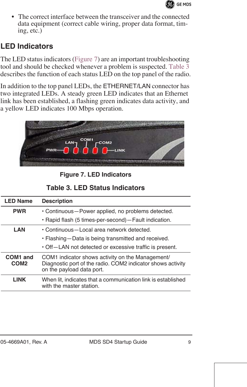
![05-4669A01, Rev. A MDS SD4 Startup Guide 7 b. Set the transmit frequency by entering TX xxx.xxxx , where xxx.xxxx is the frequency in MHz. Press . The response PROGRAMMED OK indicates successful entry.c. Set the receive frequency by entering RX xxx.xxxx , where xxx.xxxx is the frequency in MHz. Press . The response PROGRAMMED OK indicates successful entry.d. Set the radio’s bandwidth using the BW xxxx command, where xxxx equals 12.5 , or 25 kHz. NOTE: The radio’s bandwidth must be properly set before making modem settings. A modem setting will not be respected if there is insufficient bandwidth to accommodate it.e. Set the radio’s modem type using the MODEM xxxx command, where xxxx equals the bps speed of the radio (9600 or 19200 bps). An entry of NONE selects analog operation, for use with an external modem.If all checks are OK, you are finished with the installation at this site. SOFTWARE COMMAND SUMMARY Table 2 lists software commands commonly used during initial instal-lation and setup of the transceiver. For a complete list of commands and detailed descriptions, refer to the transceiver’s Reference Manual . Table 2. Command Summary Command Name Function ALARM Read current operating condition of radio. BAUD [xxxxx abc] Set or display the DATA INTERFACE data rate and control bits. BW [xxx] Sets radio’s channel bandwidth (in kHz). DKEY Dekey the radio (transmitter OFF). This is generally a radio test command. KEY Key the radio (transmitter ON). This is generally a radio test command. MODEL Display the model number of the radio. MODEM [xxxx, NONE] Set the modem characteristics of the radio.ENTERENTER](https://usermanual.wiki/GE-MDS/DS-SD4.User-Manual/User-Guide-909553-Page-9.png)
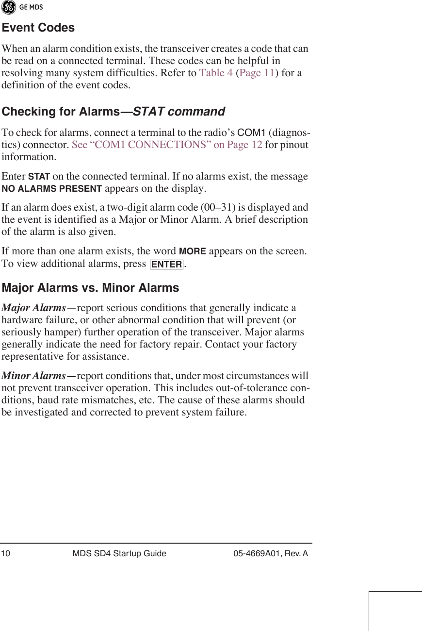
![8 MDS SD4 Startup Guide 05-4669A01, Rev. A TROUBLESHOOTING For proper operation, all radios in the network must meet these basic requirements:• Adequate and stable primary power.• Secure connections (RF, data and power)• An efficient and properly aligned antenna system with a received signal strength of at least –90 dBm. (It is possible for a system to operate with weaker signals, but reliability will be degraded.) • Proper programming of the transceiver’s operating parameters (see SOFTWARE COMMAND SUMMARY on Page 7). OWM [XXX...] Set or display the owner’s message. OWN [XXX...] Set or display the owner’s name. PORT [RS232, RS485] Selects signaling standard to be used on DATA port. PWR [20–37] Set or display the transmit power setting. RSSI Display the Received Signal Strength Indication. RTU [ON/OFF/0-80] Re-enables or disables the radio’s internal RTU simulator and sets the RTU address. RX [xxx.xxxx] Set or display receiver frequency. SER Display the radio serial number. SPECTRUM [xxx.xx x.x] Display internal spectrum analyzer, where x characters denote center frequency and span frequency in MHz, respectively. SREV Display the Software Revision Level. STAT Display radio status and alarms. TEMP Display the internal temperature of the radio in degrees C. TX [xxx.xxxx] Set or display the transmit frequency. UNIT [10000...65000] Set or display the transceiver’s unit address.Table 2. Command Summary (Cont’d)Command Name Function](https://usermanual.wiki/GE-MDS/DS-SD4.User-Manual/User-Guide-909553-Page-10.png)