Contents
- 1. User Manual
- 2. User manual
User Manual
Start-Up Guide
Firmware Release 1.x.x
MDS 05-4669A01, Rev. A
December 2007
MDS SD4
™
Software-Controlled
Digital Communications
OPERATIONAL & SAFETY NOTICES
Concentrated energy from a directional antenna may pose a health hazard to
humans. Do not allow people to come closer to the antenna than the distances
listed in the table below when the transmitter is operating. More information on
RF exposure can be found online at the following website:
www.fcc.gov/oet/info/documents/bulletins.
FCC Part 15 Notice
(Pending Approval)
The transceiver is approved under Part 15 of the FCC Rules. Operation is subject to the following two con-
ditions: (1) this device may not cause harmful interference, and (2) this device must accept any interfer-
ence received, including interference that may cause undesired operation. Any unauthorized modification
or changes to this device without the express approval of Microwave Data Systems may void the user’s
authority to operate this device. Furthermore, this device is intended to be used only when installed in
accordance with the instructions outlined in this manual. Failure to comply with these instructions may
void the user’s authority to operate this device.
CSA/us Notice
(Pending Approval)
This product is pending approval for use in Class 1, Division 2, Groups A, B, C & D Hazardous Locations.
Such locations are defined in Article 500 of the National Fire Protection Association (NFPA) publication
NFPA 70, otherwise known as the National Electrical Code. The transceiver has been recognized for use
in these hazardous locations by the Canadian Standards Association (CSA) which also issues the US mark
of approval (CSA/US). The CSA Certification is in accordance with CSA STD C22.2 No. 213-M1987.
CSA Conditions of Approval: The transceiver is not acceptable as a stand-alone unit for use in the
hazardous locations described above. It must either be mounted within another piece of equipment which
is certified for hazardous locations, or installed within guidelines, or conditions of approval, as set forth
by the approving agencies. These conditions of approval are as follows:
The transceiver must be mounted within a separate enclosure which is suitable for the intended application.
The antenna feedline, DC power cable and interface cable must be routed through conduit in accordance
with the National Electrical Code.
Installation, operation and maintenance of the transceiver should be in accordance with the transceiver's
installation manual, and the National Electrical Code. Tampering or replacement with non-factory com-
ponents may adversely affect the safe use of the transceiver in hazardous locations, and may void the
approval. A power connector with screw-type retaining screws as supplied by GE MDS must be used.
Do not disconnect equipment unless power has been switched off or
the area is known to be non-hazardous.
Refer to Articles 500 through 502 of the National Electrical Code
(NFPA 70) for further information on hazardous locations and
approved Division 2 wiring methods.
Antenna Gain vs. Recommended Safety Distance
(MDS SD4 Radio)
Antenna Gain
0–5 dBi 5–10 dBi 10–16.5 dBi
Minimum RF
Safety Distance
0.79 meter 1.41 meters 3.05 meters
RF Exposure
EXPLOSION
HAZARD!
05-4669A01, Rev. A MDS SD4 Startup Guide
1
INTRODUCTION
This guide presents basic installation and operating instructions for the
MDS SD4 Series wireless transceiver. It is a companion guide to the
MDS SD4 Series Reference Manual
(Part No. 05-4670A01). Refer to
the Reference Manual for additional details and system design infor-
mation.
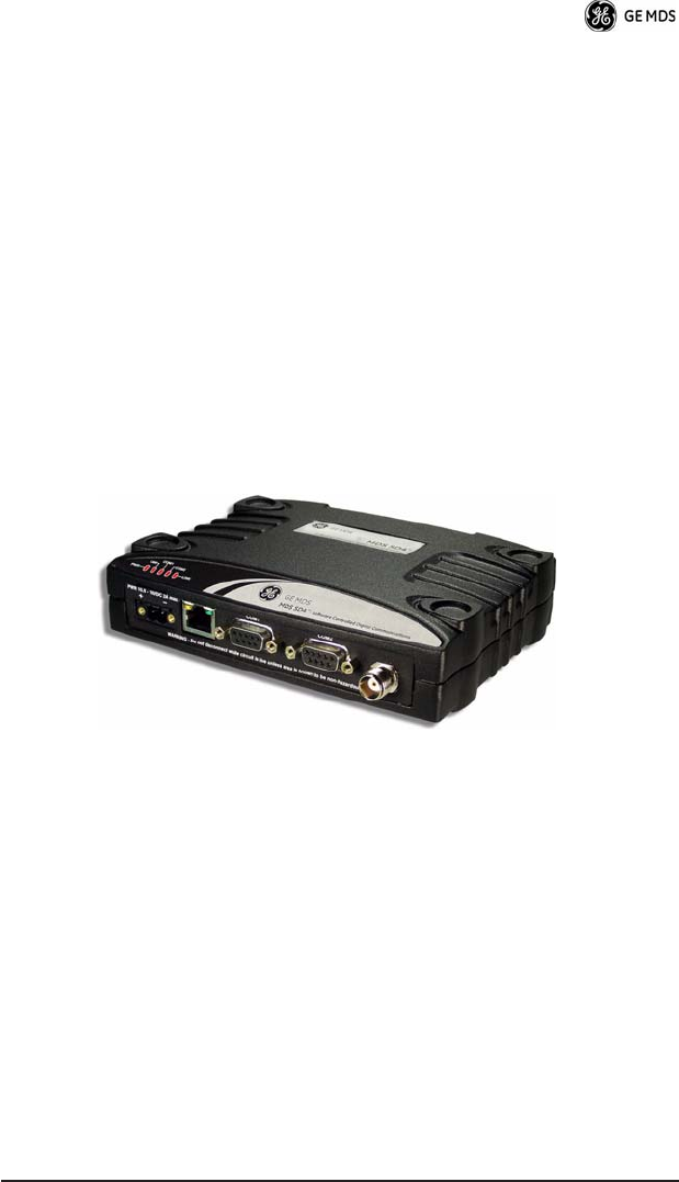
The transceiver (Figure 1) is designed to operate in point-to-multi-
point environments, including utility automation/distribution systems,
and other telemetry functions.
These radios are software-configurable to provide flexible operation
in a variety of applications using one hardware platform. They employ
microprocessor control and Digital Signal Processing (DSP) tech-
nology to provide robust communications even under adverse condi-
tions.
Figure 1. SD4 Data Transceiver
The transceiver is designed for trouble-free operation with data equip-
ment provided by other manufacturers, including remote terminal
units (RTUs), programmable logic controllers (PLCs), flow com-
puters, transaction terminals, and other similar devices.
NOTE:
Some features may not be available on all units, based on the
options purchased and the applicable regulatory constraints
for the region in which the radio will operate.
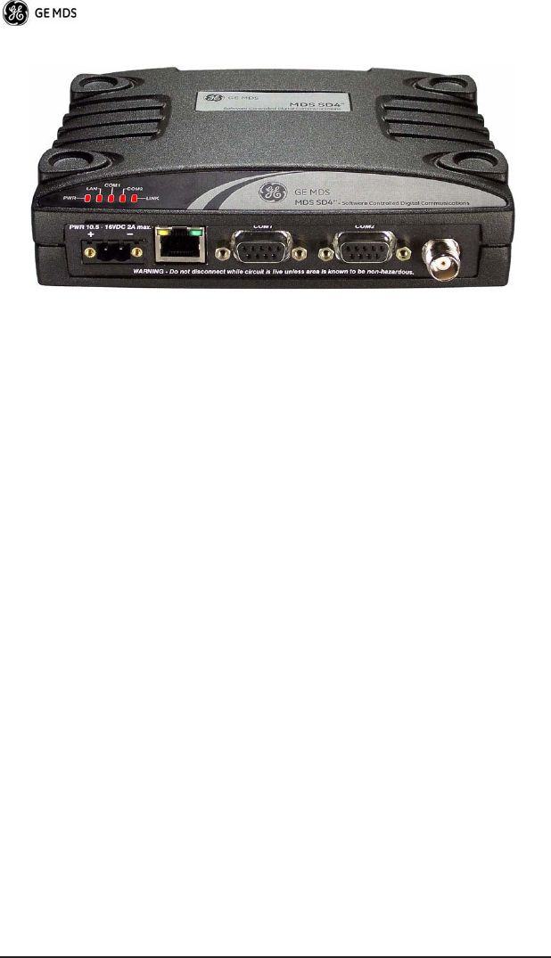
Front Panel Layout
Figure 2 shows the interface connectors and indicators on the trans-
ceiver’s front panel. These items are referenced in the installation
steps given later in this guide.
2 MDS SD4 Startup Guide 05-4669A01, Rev. A
Invisible place holder
Figure 2. Front Panel Connectors & Indicators
Connector functions
(left to right)
are as follows:
•POWER
•
LAN
(RJ-45)
•
COM1—
Management/Diagnostics (DB-9)
•
COM2—
Payload Data (DB-9)
•
ANTENNA
(TNC)
LED functions are described in Table 3 on Page 9.
Standard Accessories
Table 1 lists accessories normally shipped with the transceiver. The
contents may have been modified to reflect customer-specific require-
ments specified at the time of order. Additional accessories are avail-
able. Refer to the
SD4 Reference Manual
for a complete list.

05-4669A01, Rev. A MDS SD4 Startup Guide
3
INSTALLATION
There are three main requirements for installing the transceiver: ade-
quate and stable primary power, a good antenna system, and the cor-
rect data connections between the transceiver and the data device.
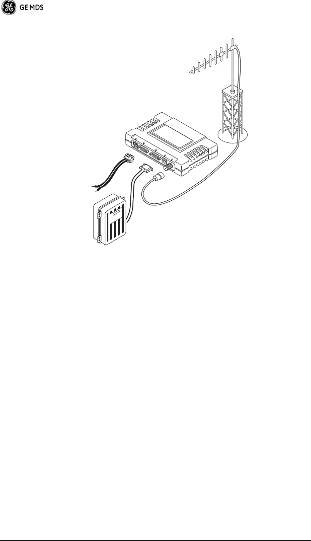
Figure 3 shows a typical remote station arrangement. This is followed
by step-by-step procedures for installing the transceiver and making
external connections.
Table 1. Accessories Supplied with the Unit
Accessory Description Part Number
DC Power Plug,
2-pin, polarized
Mates with power connector on radio.
Screw terminals provided for wires,
threaded locking screws to prevent
accidental disconnect.
73-1194A39
Radio
Configuration
Software
PC software used for setting the basic
operating parameters of the radio.
03-3156A01
Start-Up Guide Brief instructions for initial setup and
commissioning of the radio.
05-4669A01
Reference
Manual
Full technical information for the
radio, including a complete
description of software commands.
05-4670A01
4 MDS SD4 Startup Guide 05-4669A01, Rev. A
Figure 3. Typical Remote Station Arrangement
Installation Steps
Below are the basic steps for installing the transceiver. In most cases,
these steps alone are sufficient to complete the installation. Refer to
the
Reference Manual
for additional information.
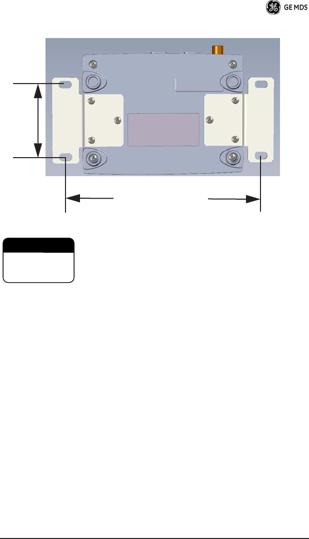
1.
Mount the transceiver to a stable surface
using the brackets
supplied with the radio. Begin by attaching the radio’s mounting
brackets to the bottom of the transceiver case (if not already
attached) using the four 6-32 x 1/4 inch (6 mm) screws supplied.
Figure 4 shows the mounting bracket dimensions.
POWER SUPPLY
10.5–16 VDC @ 2A
Negative Ground Only
TRANSCEIVER
LOW-LOSS FEEDLINE
ANTENNA
SYSTEM
DATA TELEMETRY
DEVICE
LAN COM1 COM2 PWR LINK
05-4669A01, Rev. A MDS SD4 Startup Guide
5
Invisible place holder
Figure 4. Transceiver Mounting Bracket Dimensions
Using screws longer than 1/4 inch (6 mm) may damage the
unit’s internal PC board.
2.
Install the antenna and feedline
for the station. Aim directional
antennas toward the master station. The antenna used with the
transceiver must be designed to operate in the radio’s frequency
band, and be mounted in a location that provides a clear path to
the associated master station. Use low loss coaxial feedline and
keep the cable as short as possible.
3.
Connect the data equipment
to
COM2
on the front panel. The
radio is wired as a DCE device. Most applications will require the
use of a straight-thru cable. Check Table 5 on Page 13 for pin
details.
Note: The LAN/Ethernet port is used for upgrading the radio’s
firmware. Refer to the Reference Manual for usage details.
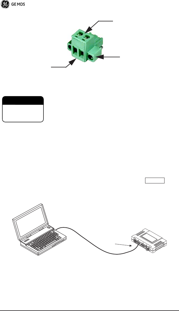
4.
Connect primary power to the transceiver.
Power applied must
be within 10.5–16 Vdc and capable of continuously providing up
to 2 Amperes. A power connector with screw-terminals is pro-
vided with each unit (see Figure 5). Strip the wire leads to 6 mm
(1/4 inch) and insert in the wire ports. Be sure to observe proper
polarity as shown in the Figure 5.
7.25˝ (16.99 cm)
2.75˝ (7 cm)
CAUTION
POSSIBLE
EQUIPMENT
DAMAGE
6 MDS SD4 Startup Guide 05-4669A01, Rev. A
Invisible place holder
Figure 5. DC Power Connector
The transceiver must be used with negative-ground sys-
tems only. The power supply used with the transceiver
should be equipped with overload protection (NEC
Class 2 rating), to protect against a short circuit between
its output terminals and the radio’s power connector.
5.
Set the radio’s configuration.
The transceiver is designed for
quick installation with a minimum of software configuration
required.
a. Connect a PC to the transceiver’s DB-9
COM1
connector as
shown in Figure 6 using a straight-through cable. Launch a
terminal communications program, such as HyperTerminal
(included with most Windows
TM
systems). Press a
few times to receive the ready “>” prompt on the screen.
Invisible place holder
Figure 6. PC Configuration Setup
Lead
Screws (2)
Binding
Wire Ports (2)
(Polarity: Left +, Right –)
Retaining
Screws (2)
CAUTION
POSSIBLE
EQUIPMENT
DAMAGE
ENTER
PC Running Terminal Session
(19,2000 bps, 8N1) Transceiver
LAN COM1 COM2 PWR LINK
To COM1 Port

05-4669A01, Rev. A MDS SD4 Startup Guide
7
b. Set the transmit frequency by entering
TX xxx.xxxx
, where
xxx.xxxx
is the frequency in MHz. Press
.
The
response
PROGRAMMED OK
indicates successful entry.
c. Set the receive frequency by entering
RX xxx.xxxx
, where
xxx.xxxx
is the frequency in MHz. Press
.
The
response
PROGRAMMED OK
indicates successful entry.
d. Set the radio’s bandwidth using the
BW xxxx
command, where
xxxx
equals
12.5
, or
25
kHz.
NOTE:
The radio’s bandwidth must be properly set
before
making
modem settings. A modem setting will not be respected if
there is insufficient bandwidth to accommodate it.
e. Set the radio’s modem type using the
MODEM xxxx
command,
where xxxx equals the bps speed of the radio (9600 or 19200
bps). An entry of
NONE
selects analog operation, for use with
an external modem.
If all checks are OK, you are finished with the installation at this site.
SOFTWARE COMMAND SUMMARY
Table 2 lists software commands commonly used during initial instal-
lation and setup of the transceiver. For a complete list of commands
and detailed descriptions, refer to the transceiver’s
Reference Manual
.
Table 2. Command Summary
Command Name Function
ALARM
Read current operating condition of radio.
BAUD [xxxxx abc]
Set or display the DATA INTERFACE data
rate and control bits.
BW [xxx]
Sets radio’s channel bandwidth (in kHz).
DKEY
Dekey the radio (transmitter OFF). This is
generally a radio test command.
KEY
Key the radio (transmitter ON). This is
generally a radio test command.
MODEL
Display the model number of the radio.
MODEM [xxxx, NONE]
Set the modem characteristics of the radio.
ENTER
ENTER

8 MDS SD4 Startup Guide 05-4669A01, Rev. A
TROUBLESHOOTING
For proper operation, all radios in the network must meet these basic
requirements:
• Adequate and stable primary power.
• Secure connections (RF, data and power)
• An efficient and properly aligned antenna system with a
received signal strength of at least –90 dBm. (It is possible for a
system to operate with weaker signals, but reliability will be
degraded.)
• Proper programming of the transceiver’s operating parameters
(see SOFTWARE COMMAND SUMMARY on Page 7).
OWM [XXX...]
Set or display the owner’s message.
OWN [XXX...]
Set or display the owner’s name.
PORT [RS232, RS485]
Selects signaling standard to be used on
DATA port.
PWR [20–37]
Set or display the transmit power setting.
RSSI
Display the Received Signal Strength
Indication.
RTU [ON/OFF/0-80]
Re-enables or disables the radio’s internal
RTU simulator and sets the RTU address.
RX [xxx.xxxx]
Set or display receiver frequency.
SER
Display the radio serial number.
SPECTRUM
[xxx.xx x.x]
Display internal spectrum analyzer, where
x
characters denote center frequency and
span frequency in MHz, respectively.
SREV
Display the Software Revision Level.
STAT
Display radio status and alarms.
TEMP
Display the internal temperature of the radio
in degrees C.
TX [xxx.xxxx] Set or display the transmit frequency.
UNIT [10000...65000] Set or display the transceiver’s unit address.
Table 2. Command Summary (Cont’d)
Command Name Function
05-4669A01, Rev. A MDS SD4 Startup Guide 9
• The correct interface between the transceiver and the connected
data equipment (correct cable wiring, proper data format, tim-
ing, etc.)
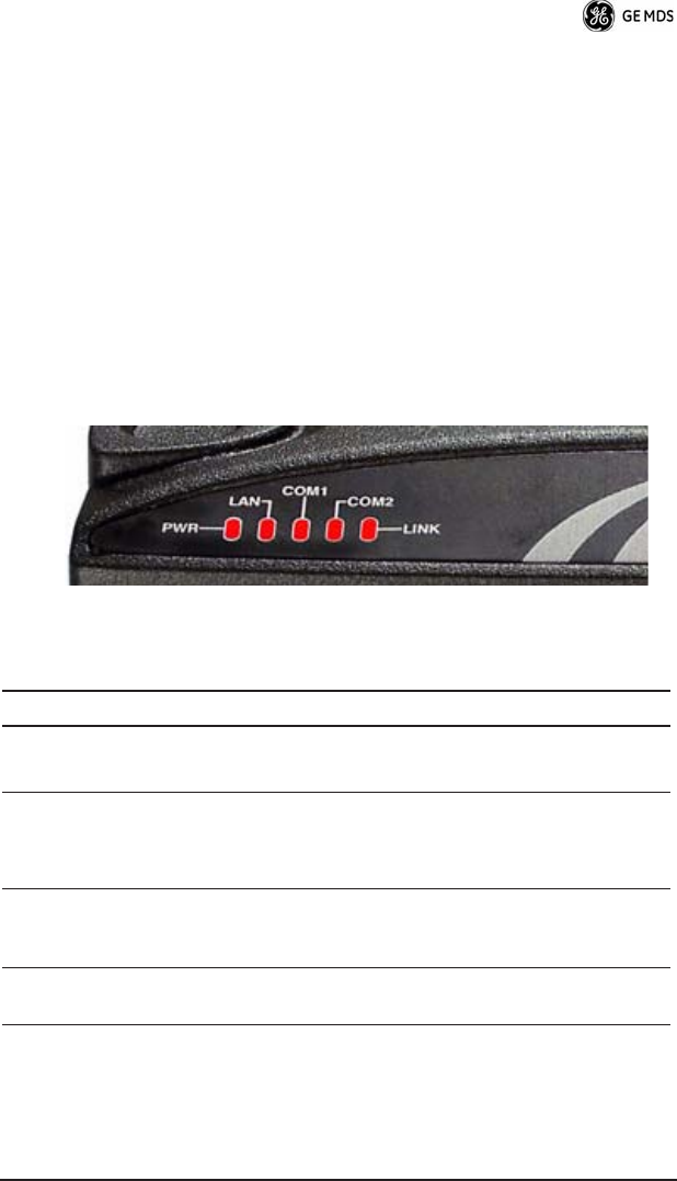
LED Indicators
The LED status indicators (Figure 7) are an important troubleshooting
tool and should be checked whenever a problem is suspected. Table 3
describes the function of each status LED on the top panel of the radio.
In addition to the top panel LEDs, the ETHERNET/LAN connector has
two integrated LEDs. A steady green LED indicates that an Ethernet
link has been established, a flashing green indicates data activity, and
a yellow LED indicates 100 Mbps operation.
Invisible place holder
Figure 7. LED Indicators
Table 3. LED Status Indicators
LED Name Description
PWR • Continuous—Power applied, no problems detected.
• Rapid flash (5 times-per-second)—Fault indication.
LAN • Continuous—Local area network detected.
• Flashing—Data is being transmitted and received.
• Off—LAN not detected or excessive traffic is present.
COM1 and
COM2
COM1 indicator shows activity on the Management/
Diagnostic port of the radio. COM2 indicator shows activity
on the payload data port.
LINK When lit, indicates that a communication link is established
with the master station.

10 MDS SD4 Startup Guide 05-4669A01, Rev. A
Event Codes
When an alarm condition exists, the transceiver creates a code that can
be read on a connected terminal. These codes can be helpful in
resolving many system difficulties. Refer to Table 4 (Page 11) for a
definition of the event codes.
Checking for Alarms—STAT command
To check for alarms, connect a terminal to the radio’s COM1 (diagnos-
tics) connector. See “COM1 CONNECTIONS” on Page 12 for pinout
information.
Enter STAT on the connected terminal. If no alarms exist, the message
NO ALARMS PRESENT appears on the display.
If an alarm does exist, a two-digit alarm code (00–31) is displayed and
the event is identified as a Major or Minor Alarm. A brief description
of the alarm is also given.
If more than one alarm exists, the word MORE appears on the screen.
To view additional alarms, press .
Major Alarms vs. Minor Alarms
Major Alarms—report serious conditions that generally indicate a
hardware failure, or other abnormal condition that will prevent (or
seriously hamper) further operation of the transceiver. Major alarms
generally indicate the need for factory repair. Contact your factory
representative for assistance.
Minor Alarms—report conditions that, under most circumstances will
not prevent transceiver operation. This includes out-of-tolerance con-
ditions, baud rate mismatches, etc. The cause of these alarms should
be investigated and corrected to prevent system failure.
ENTER

05-4669A01, Rev. A MDS SD4 Startup Guide 11
Event Code Definitions
Table 4 contains a listing of event codes that may be reported by the
transceiver. The codes shown are a subset of a larger pool of codes
used for various GE MDS products. For this reason, the table does not
show a sequential listing of all code numbers. Only the codes appli-
cable to this product are shown.
Internal Spectrum Analyzer
The radio contains a built-in spectrum analyzer tool that can be dis-
played on a connected PC. This utility is helpful in diagnosing inter-
ference problems, or for use during initial setup of the radio.
Table 4. Event Codes
Event
Code
Event
Class Description
01 Major Improper software detected for this radio model.
04 Major One or both of the internal programmable
synthesizer loops is reporting an out-of-lock
condition.
08 Major The system is reporting that it has not been
calibrated. Factory calibration is required for proper
radio operation.
12 Major Receiver time-out. No data received within the
specified receiver time-out time.
17 Minor A data parity fault has been detected on the COM2
INTERFACE connector. This usually indicates a
parity setting mismatch between the radio and the
RTU.
18 Minor A data framing error has been detected on the
COM2 INTERFACE connector. This may indicate a
baud rate mismatch between the radio and the RTU.
26 Minor The DC input voltage is out-of-tolerance. If the
voltage is too far out of tolerance, operation may fail.
31 Minor The transceiver’s internal temperature is
approaching an out-of-tolerance condition. If the
temperature drifts outside of the recommended
operating range, system operation may fail.
12 MDS SD4 Startup Guide 05-4669A01, Rev. A
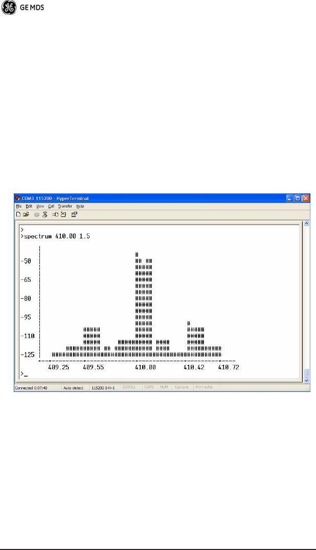
The spectrum analyzer display is accessed by entering spectrum xxx.xx
x.x at the command prompt, where the x characters denote the center
frequency and span frequency, respectively. The frequencies are
entered in megahertz. For example, a sample entry would be spectrum
410.00 1.5, corresponding to a center operating frequency of 410.00
MHz and a span (sweep width) of 1.5 MHz.
A sample display with these parameters is shown in Figure 8. The dis-
play creates a received signal strength indication (RSSI) vs. frequency
plot for the center frequency and all surrounding signals within the
span. By analyzing the display, you can determine the presence of
other signals near the transceiver’s operating frequency. Refer to the
SD4 Reference Manual for additional details.
Invisible place holder
Figure 8. Internal Spectrum Analyzer Display
COM1 CONNECTIONS
The COM1 connector is used to connect a PC to the radio for manage-
ment or diagnostics. A straight-through cable is required that connects
Pin 2 (RXD), Pin 3 (TXD), and Pin 5–Ground. (See Figure 9.)
05-4669A01, Rev. A MDS SD4 Startup Guide 13
Invisible place holder
Figure 9. COM1 Wiring to Computer
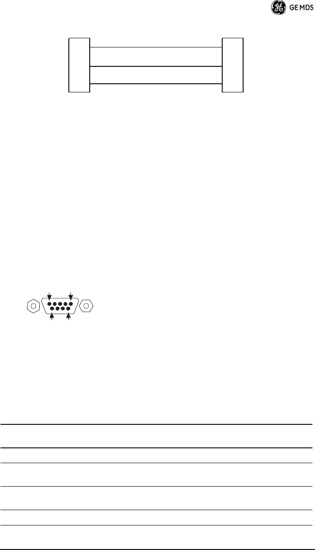
COM2 CONNECTIONS
The COM2 connector (Figure 10) is used to connect the radio to an
external DTE telemetry device that supports the EIA/RS-232 or
EIA/RS-485 (balanced) format, depending on how the radio is config-
ured. The radio supports data rates of 300, 1200, 2400, 4800, 9600,
19200, 38400, 57600, and 115200 bps (asynchronous data only).
The COM2 connector mates with a standard DB-9 plug that is avail-
able from many electronics parts distributors. Table 5 and Table 6 pro-
vide detailed pin descriptions for the DATA connector in RS/EIA-232
mode and RS/EIA-485 mode, respectively.
Pin Descriptions—RS/EIA-232 Mode
Table 5 lists the COM connector pin functions when configured to
operate in RS/EIA-232 mode.
NOTE: The radio is hard-wired as a DCE device in EIA-232 mode.
Figure 10. COM2 Connector (DB-9F)
As viewed from outside the radio
Table 5. COM2 Pin Descriptions—RS/EIA-232
Pin
Number
Input/
Output Pin Description
1 OUT DCD (Data Carrier Detect)
2 OUT RXD (Received Data)
Supplies received data to the connected device.
3 IN TXD (Transmitted Data)
Accepts TX data from the connected device.
4 -- Not Used—Do not connect
RXD
TXD
GND
2
3
5
RXD
TXD
GND
2
3
5
>
<
DB-9 FEMALE
(COMPUTER)
DB-9 MALE
(RADIO SIDE)
5
96
1

14 MDS SD4 Startup Guide 05-4669A01, Rev. A
Pin Descriptions—RS/EIA-422/485 Mode
Table 6 lists the COM connector pin functions for radios configured to
operate in RS/EIA-422/485 mode. See Figure 11 for wiring schemes.
NOTES:
• RXD+ / RXA and RXD– / RXB are data sent into the radio to be transmitted out
• RXD+ / RXA is positive with respect to RXD– / RXB when the line input is a “0”
• TXD+ / TXA and TXD– / TXB are data received by the radio and sent to the connected
device
• TXD+ / TXA is positive with respect to the TXD– / TXB when the line output is a “0”
5 -- Signal Ground—
Connects to ground (negative supply potential) on chassis.
6 OUT Alarm Output (DSR)—An RS-232 high/space (+5.0 Vdc) on
this pin indicates an alarm condition. An RS-232 low/mark
(–5.0 Vdc) indicates normal operation. This pin may be used
as an alarm output. (See Reference Manual.)
7 IN RTS (Request-to-Send)
8 OUT CTS (Clear-to-Send)—Goes “high” after the programmed
CTS delay time has elapsed (DCE), or keys an attached ra-
dio when RF data arrives (CTS KEY).
9 -- Not Used—Do not connect
Table 6. COM2 Connector Pin Descriptions—RS/EIA-485 Mode
Pin
Number
Input/
Output Pin Description
1 — Not Used—Do not connect
2 OUT TXD+/TXA—Non-inverting driver output. Supplies data to
the connected device.
3 IN RXD+/RXA—Non-inverting receiver input. Accepts data
from the connected device.
4 -- Not Used—Do not connect
5 -- Signal Ground—Connects to ground (negative supply po-
tential) on the radio’s PC board and chassis.
6 -- Not Used—Do not connect
7 IN RXD– /RXB—Inverting receiving input
8 OUT TXD– /TXB—Inverting driver output.
9 -- Open (User configurable via internal jumper. See Reference
Manual for details.)
Table 5. COM2 Pin Descriptions—RS/EIA-232 (Cont’d)
Pin
Number
Input/
Output Pin Description

05-4669A01, Rev. A MDS SD4 Startup Guide 15
Invisible place holder
Figure 11. EIA-422/485 Wiring Schemes
(Left: EIA-422, Right: EIA-485)
SPECIFICATIONS
GENERAL
Frequency Range*: MDS SD4: 330–512 MHz in one of 3
bands as follows:
Band 1—330 to 400 MHz
Band 2—400 to 450 MHz
Band 3—450 to 512 MHz
* Specific frequency authorizations are dependent on the type-approval of
radio. Consult the factory for details.
RECEIVER
Maximum Usable Sensitivity: –110 dBm at 1x10⁻⁶ BER (Preliminary)
Bandwidth: 12.5, 25 kHz
TRANSMITTER
Carrier Power: 0.1 Watts to 5 Watts
Duty Cycle: Continuous
Output Impedance: 50 Ω
Channel Spacing: 12.5, 25 kHz
FCC Emission Designators:
12.5 kHz B/W: 11KOF1D, 11KOF2D, 11KOF3D
25.0 kHz B/W: 23K4F1D, 23K4F2D, 23K4F3D
DATA CHARACTERISTICS
Signaling Type: EIA/RS-232; DB-9 Female connector
Data Interface Rates: 300–115200 bps, asynchronous
Data Latency: 10 ms maximum
2-WIRE CONNECTIONS4-WIRE CONNECTIONS
TXD +
RXD +
2
3
7
RADIO
DATA CONNECTOR
8
RXD –
TXD –
EXTERNAL DEVICE
RXD –
TXD +
RXD +
TXD –
RXD+/TXD+
2
3
7
RADIO
DATA CONNECTOR
8RXD–/TXD–
EXTERNAL DEVICE
RXD –
TXD +
RXD +
TXD –

16 MDS SD4 Startup Guide 05-4669A01, Rev. A
PRIMARY POWER
Voltage: 13.8 Vdc Nominal (10.5 to 16 Vdc)
Negative-Ground Systems Only
TX Supply Current: 2.0 Amperes (Maximum) @ 5 Watts RF
Output
RX Supply Current: Operational—125 mA, Nominal
Fuse: 4-Amp Thermal Fuse, Self-Resetting,
Internal
(Remove primary power to reset)
ENVIRONMENTAL
Humidity: 95% at 40 degrees C (104°F),
non-condensing
Temperature Range: –30 to 60 degrees C (–22°F to +140°F)
Weight: 1.0 kilograms
DIAGNOSTICS INTERFACE
Signaling Standard: RS-232 (COM1)
RS-232/RS-485 (COM2)
Connector: COM1—DB-9F
COM2—DB-9F
Specifications are subject to change without notice or obligation.

Installation Guide

GE MDS, LLC
Rochester, NY 14620
General Business: +1 585 242-9600
FAX: +1 585 242-9620
Web: www.GEmds.com
175 Science Parkway