GE MDS DS-SD9 Wireless Data Transceiver SD9 User Manual 4669B MDS SDx Data Xcvr Body
GE MDS LLC Wireless Data Transceiver SD9 4669B MDS SDx Data Xcvr Body
UserManual.wiki
>
GE MDS
>
DS SD9 User Manual
User Manual
Navigation menu
Upload a User Manual
Namespaces
Wiki Guide
HTML
PDF
Info
Views
User Manual
Discussion / Help
Navigation
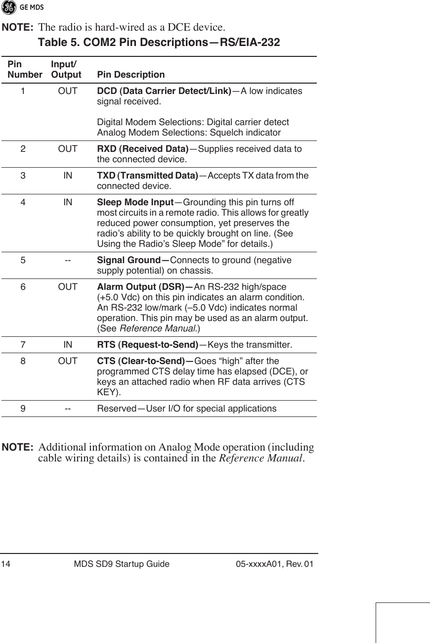
![8 MDS SD9 Startup Guide 05-xxxxA01, Rev. 01 SOFTWARE COMMAND SUMMARY Table 2 lists software commands commonly used during initial instal-lation and setup of the transceiver. A complete list of commands and detailed descriptions is contained in the Reference Manual . Table 2. Command Summary Command Name FunctionBAUD [xxxx xxx] Sets radio’s serial data interface rate/format. Default setting is BAUD 9600 8N1. DATAKEY Keys the transmitter on receipt of data. DKEY Dekey the radio (transmitter OFF). This is generally a radio test command. KEY Key the radio (transmitter ON). This is generally a radio test command. MODEM [xxxx] Set the modem characteristics of the radio. PORT [RS232, RS485] Selects signaling standard to be used on COM2 DATA port. For RS-485 operation, see Reference Manual . PWR [20–37] Set or display the transmit power setting. PTTSIG [ON, OFF] Set/display push-to-talk configuration. RSSI Display the Received Signal Strength Indication. RTSKEY Set/display how the radio responds to RTS keying. Default is RTSKEY ON, which causes the radio to key the transmitter when RTS is raised. RTU [ON/OFF/0-80] Re-enables or disables the radio’s internal RTU simulator and sets the RTU address. RX [xxx.xxxx] Set or display receiver frequency. SER Display the radio serial number. SNR Signal-to-Noise Ratio (in dB). SPECTRUM [xxx.xx] Display internal spectrum analyzer, where xxx.xx characters denote center frequency in MHz. The command spectrum may be entered alone to view current operating channel. SREV Display the Software Revision Level.](https://usermanual.wiki/GE-MDS/DS-SD9/User-Guide-1142995-Page-10.png)
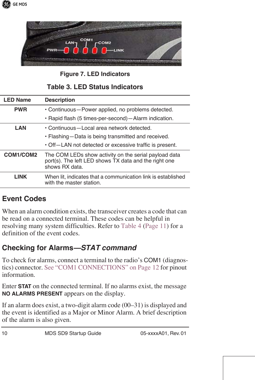
![05-xxxxA01, Rev. 01 MDS SD9 Startup Guide 9 TROUBLESHOOTING For proper operation, all radios in the network must meet these basic requirements:• Adequate and stable primary power• Secure connections (RF, data and power)• A clear transmission path between stations• An efficient and properly aligned antenna system providing adequate received signal strength.• Proper programming of the transceiver’s operating parameters• The correct interface between the transceiver and the connected data equipment (correct cable wiring, proper data format, tim-ing, etc.) LED Indicators The LED status indicators (Figure 7) are an important troubleshooting aid and should be checked whenever a problem is suspected. Table 3 describes the function of each status LED on the top panel of the radio.In addition to the top panel LEDs, the ETHERNET/LAN connector has two integrated LEDs. A steady green LED indicates that an Ethernet link has been established, a flashing green indicates data activity, and a yellow LED indicates 100 Mbps operation. STAT Display radio status and alarms. TEMP Display the internal temperature of the radio in degrees C. TX [xxx.xxxx] Set or display the transmit frequency. Table 2. Command Summary (Cont’d) Command Name Function](https://usermanual.wiki/GE-MDS/DS-SD9/User-Guide-1142995-Page-11.png)