GE MDS DS-SD9 Wireless Data Transceiver SD9 User Manual 4669B MDS SDx Data Xcvr Body
GE MDS LLC Wireless Data Transceiver SD9 4669B MDS SDx Data Xcvr Body
GE MDS >
User Manual
Start-Up Guide
Preliminary
MDS 05-4659A01, Rev. 0
JULY2008
MDS SD9
™
Software-Controlled
Digital Communications

OPERATIONAL & SAFETY NOTICES
Concentrated energy from a directional antenna may pose a health hazard to
humans. Do not allow people to come closer to the antenna than the distances
listed in the table below when the transmitter is operating. More information on
RF exposure can be found online at the following website:
www.fcc.gov/oet/info/documents/bulletins.
FCC Part 15 Notice
Users must comply with the following requirements:
Operation of this device is subject to the following two conditions: (1) this device may not cause harmful
interference, and (2) this device must accept any interference received, including interference that may
cause undesired operation. Any unauthorized modification or changes to this device without the express
approval of the manufacturer may void the user’s authority to operate this device. Furthermore, this device
is intended to be used only when installed in accordance with the instructions outlined in this manual.
Failure to comply with these instructions may void the user’s authority to operate this device.
CSA/us Notice
This product is pending approval for use in Class 1, Division 2, Groups A, B, C & D Hazardous Locations.
Such locations are defined in Article 500 of the National Fire Protection Association (NFPA) publication
NFPA 70, otherwise known as the National Electrical Code. The transceiver has been recognized for use
in these hazardous locations by the Canadian Standards Association (CSA) which also issues the US mark
of approval (CSA/US). The CSA Certification is in accordance with CSA STD C22.2 No. 213-M1987.
CSA Conditions of Approval: The transceiver is not acceptable as a stand-alone unit for use in the
hazardous locations described above. It must either be mounted within another piece of equipment which
is certified for hazardous locations, or installed within guidelines, or conditions of approval, as set forth
by the approving agencies. These conditions of approval are as follows:
The transceiver must be mounted within a separate enclosure which is suitable for the intended applica-
tion.The antenna feedline, DC power cable and interface cable must be routed through conduit in accor-
dance with the National Electrical Code.
Installation, operation and maintenance of the transceiver should be in accordance with the transceiver's
installation manual, and the National Electrical Code. Tampering or replacement with non-factory com-
ponents may adversely affect the safe use of the transceiver in hazardous locations, and may void the
approval. A power connector with screw-type retaining screws as supplied by GE MDS must be used.
Do not disconnect equipment unless power has been switched off or
the area is known to be non-hazardous. Refer to Articles 500 through
502 of the National Electrical Code (NFPA 70) for further information
on hazardous locations and approved Division 2 wiring methods.
Antenna Gain vs. Recommended Safety Distance
(MDS SD9 Radio)
Antenna Gain
0–5 dBi 5–10 dBi 10–16.5 dBi
Minimum RF
Safety Distance
0.46 meter .82 meters 1.74 meters
RF Exposure
EXPLOSION
HAZARD!
05-xxxxA01, Rev. 01 MDS SD9 Startup Guide
1
INTRODUCTION
This guide presents basic installation and operating instructions for the
MDS SD9 Series wireless transceiver.
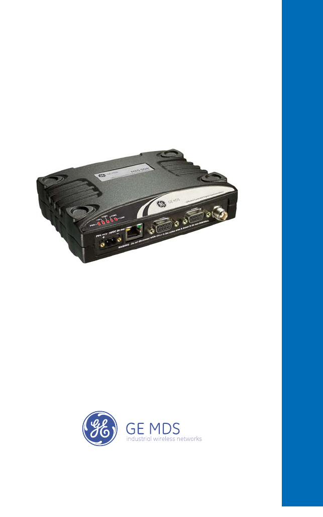
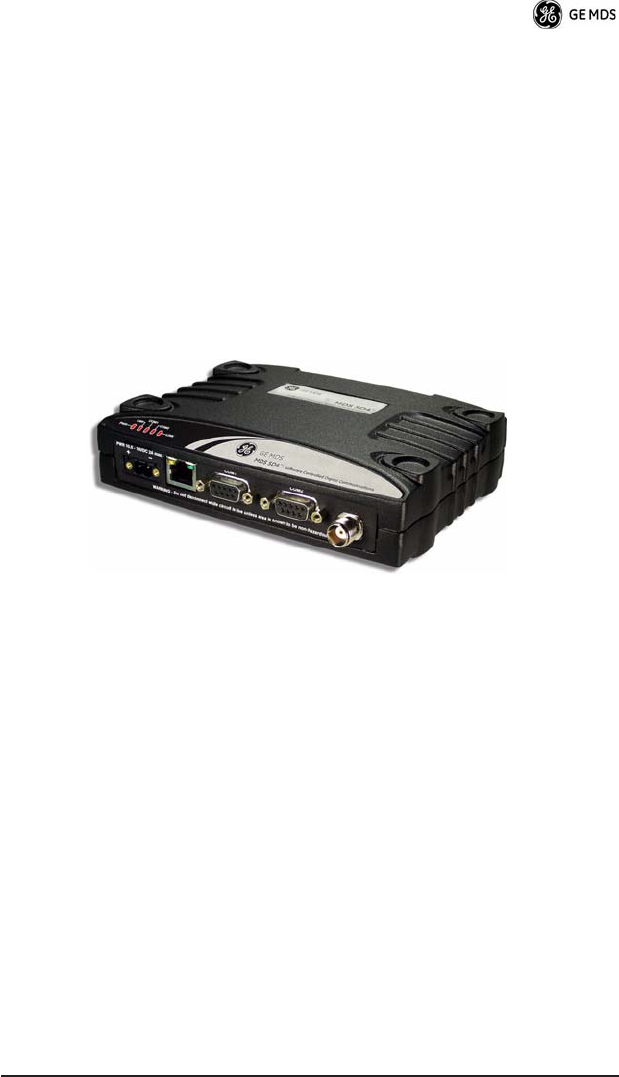
The transceiver (Figure 1) is designed to operate in point-to-multi-
point environments, including utility automation/distribution systems,
and other telemetry functions.
These radios are software-configurable to provide flexible operation
in a variety of applications using one hardware platform. They employ
microprocessor control and Digital Signal Processing (DSP) tech-
nology to provide robust communications even under adverse condi-
tions.
Figure 1. SD9 Data Transceiver
The transceiver is designed for trouble-free operation with data equip-
ment provided by other manufacturers, including remote terminal
units (RTUs), programmable logic controllers (PLCs), flow com-
puters, transaction terminals, and similar devices.
NOTE:
Some features may not be available on all units, based on the
options purchased and the applicable regulatory constraints
for the region in which the radio will operate.
Front Panel Connectors
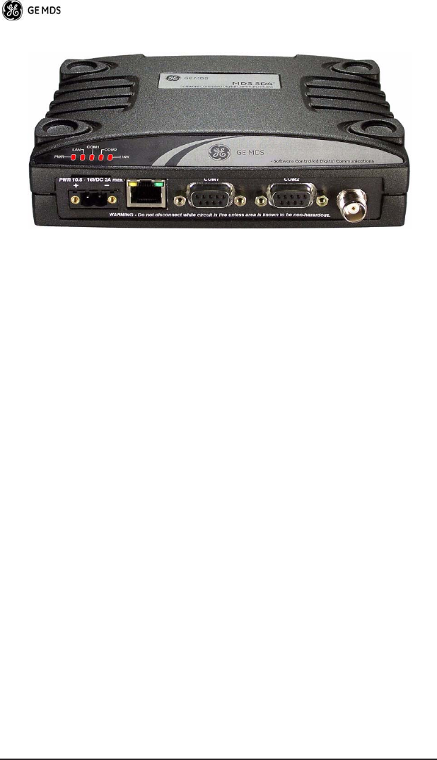
Figure 2 shows the interface connectors and indicators on the trans-
ceiver’s front panel. These items are referenced in the installation
steps given later in this guide.
2 MDS SD9 Startup Guide 05-xxxxA01, Rev. 01
Invisible place holder
Figure 2. Front Panel Connectors & Indicators
Connector functions (left to right) in Figure 2 are as follows:
•
POWER
•
LAN
(RJ-45)
•
COM1—
Management/Diagnostics (DB-9)
•
COM2—
Payload Data (DB-9)
•
ANTENNA
(TNC)
A list of LED functions is presented in Table 3 on Page 10.
Accessories
Table 1 lists available accessories for the transceiver. The contents of
a shipment may have been modified to reflect customer-specific
requirements given at the time of order. Additional accessories are
available for our products. Contact your factory representative for
assistance.

05-xxxxA01, Rev. 01 MDS SD9 Startup Guide
3
INSTALLATION
There are three main requirements for installing the transceiver:
• Adequate and stable primary power
• An efficient and properly installed antenna system
• Correct data connections between the transceiver and the data
device.
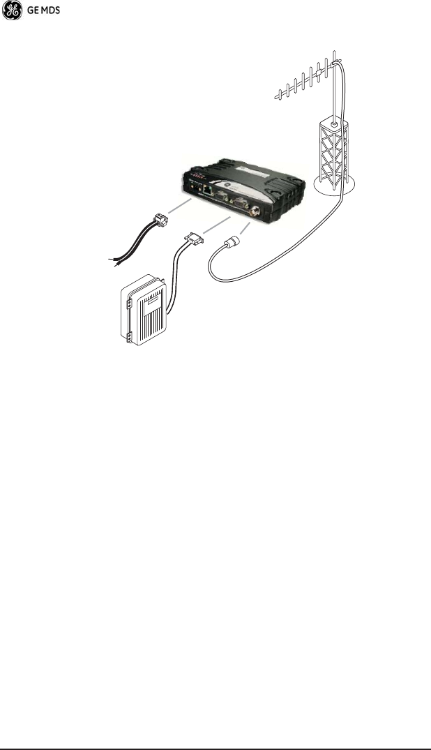
Figure 3 shows a typical remote station arrangement. This is followed
by step-by-step procedures for installing the transceiver and making
front panel connections.
Table 1. SD9 Available Accessories
Accessory Description Part Number
DC Power Plug,
2-pin, polarized
Mates with power connector on
radio. Screw terminals provided for
wires, threaded locking screws to
prevent accidental disconnect.
73-1194A39
Retrofit Kit, Digital Contains all items needed to replace
an existing MDS x710A/C/M digital
transceiver.
98-6190ACC1
Retrofit Kit, Analog Contains all items needed to replace
an existing MDS x710A/C/M
transceiver used in the analog
mode.
98-6190ACC2
Reference Manual Contains technical information,
system design data, and a complete
list of software commands.
05-4670A01
4 MDS SD9 Startup Guide 05-xxxxA01, Rev. 01
Figure 3. Typical Remote Station Arrangement
Installation Steps
Below are the basic steps for installing the transceiver. In most cases,
these steps alone are sufficient to complete the installation. Refer to
the
Reference Manual
for additional details, if required.
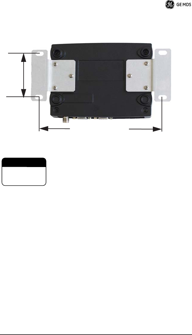
1.
Mount the transceiver to a stable surface
using the brackets
supplied with the radio. Begin by attaching the radio’s mounting
brackets to the bottom of the transceiver case (if not already
attached) using the four 6-32 x 1/4 inch (6 mm) screws supplied.
Figure 4 shows the mounting bracket dimensions.
NOTE:
To prevent moisture from entering the radio, do not mount the
case with the cable connectors pointing up. Also, dress all
cables to prevent moisture from running along the cables and
into the radio.
POWER SUPPLY
10.5–16 VDC @ 2A
Negative Ground Only
TRANSCEIVER
LOW-LOSS FEEDLINE
ANTENNA
SYSTEM
DATA TELEMETRY
DEVICE
05-xxxxA01, Rev. 01 MDS SD9 Startup Guide
5
Invisible place holder
Figure 4. Transceiver Mounting Bracket Dimensions
Using screws longer than 1/4 inch (6 mm) to attach the
brackets to the radio may damage the internal PC
board. Use only the supplied screws.
2.
Install the antenna and feedline
for the station. Aim directional
antennas toward the master station. The antenna used with the
transceiver must be designed to operate in the radio’s frequency
band, and be mounted in a location that provides a clear path to
the associated master station. Use low loss coaxial feedline and
keep the cable as short as possible.
3.
Connect the data equipment
to
COM2
on the front panel. The
radio is hardwired as a DCE device. A straight-thru cable may be
used in most applications. Check Table 5 on Page 14 for pin wir-
ing details.
Note: The radio’s LAN port is used for reprogramming the radio’s
firmware. Refer to the Reference Manual for details.
4.
Connect primary power to the transceiver.
Power applied must
be within 10.5–30 Vdc and capable of continuously providing at
least 2.5 Amperes. A power connector with screw-terminals is pro-
7.25˝ (16.99 cm)
2.75˝ (7 cm)
CAUTION
POSSIBLE
EQUIPMENT
DAMAGE
6 MDS SD9 Startup Guide 05-xxxxA01, Rev. 01
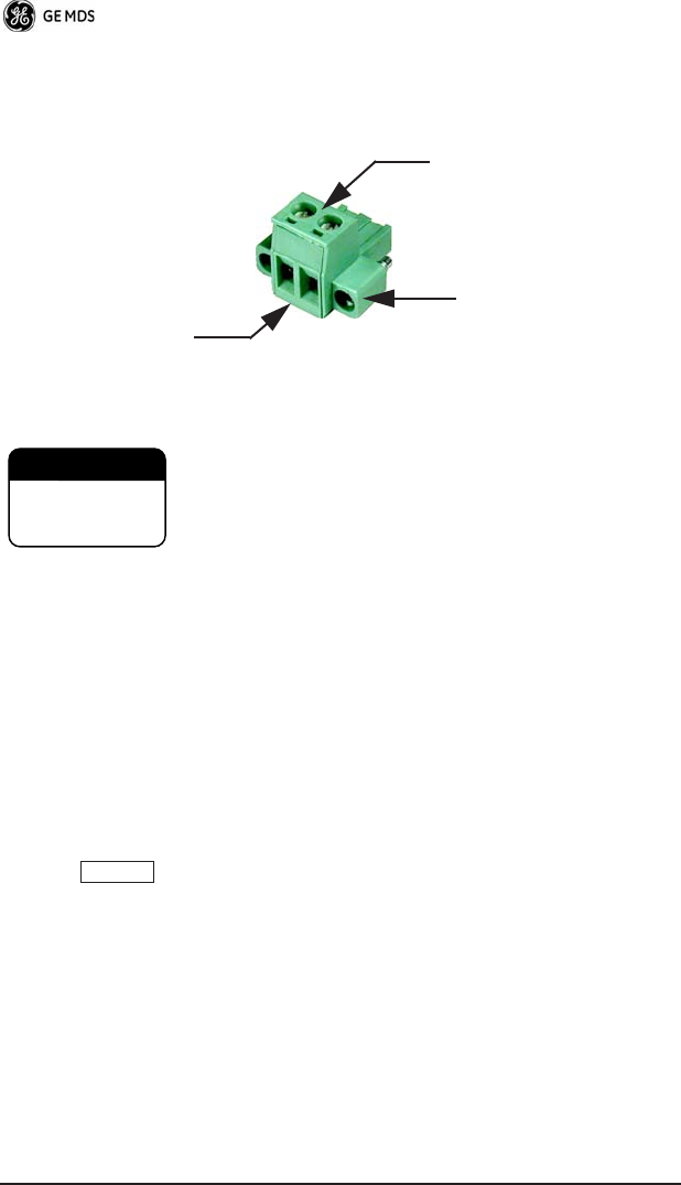
vided with each unit (see Figure 5). Strip the wire leads to 6 mm
(1/4 inch) and insert in the wire ports. Be sure to observe proper
polarity as shown in the Figure 5.
Invisible place holder
Figure 5. DC Power Connector
The transceiver is designed for use with nega-
tive-ground systems only. The power supply should be
equipped with overload protection (NEC Class 2 rating),
to protect against a short circuit between its output ter-
minals and the radio’s power connector.
5.
Set the radio’s configuration.
The transceiver is designed for
quick installation with a minimum of software configuration
required.
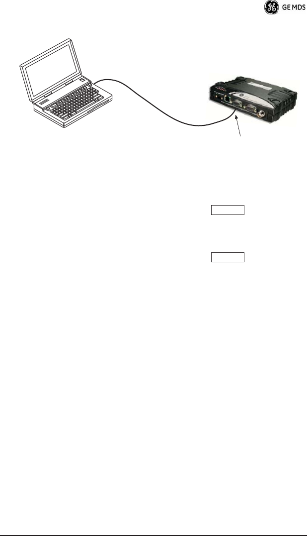
a. Connect a PC to the transceiver’s DB-9
COM1
connector as
shown in Figure 6. A straight-through cable may be used in
most applications. If desired, a cable may be built using the
information shown on Page 12 of this guide.
b. Launch a terminal communications program, such as Hyper-
Terminal (included with most Windows
TM
systems). Press the
key a few times (at half-second intervals) to receive
the ready “>” prompt on the screen.
NOTE:
To prevent unintended keying of the transmitter during
management activities, set
PTTSIG
to
OFF
, or do not
connect to Pin 6 of the
COM1
port.
Lead
Screws (2)
Binding
Wire Ports (2)
(Polarity: Left +, Right –)
Retaining
Screws (2)
CAUTION
POSSIBLE
EQUIPMENT
DAMAGE
ENTER
05-xxxxA01, Rev. 01 MDS SD9 Startup Guide
7
Invisible place holder
Figure 6. PC Configuration Setup
c. Set the transmit frequency by entering
TX xxx.xxxx
, where
xxx.xxxx
is the frequency in MHz. Press
.
The
response
PROGRAMMED OK
indicates successful entry.
d. Set the receive frequency by entering
RX xxx.xxxx
, where
xxx.xxxx
is the frequency in MHz. Press
.
The
response
PROGRAMMED OK
indicates successful entry.
e. Set the radio’s modem type if necessary, using the
MODEM
xxxx
command, where
xxxx
is the modem selection (typically
4800
or
9600
). The default setting is
9600
.
f. Set the radio’s serial data interface rate (typically
BAUD 9600
8N1
).
This completes the initial setup and configuration of the radio.
PC Running Terminal Session
Transceiver
To COM1 Port
ENTER
ENTER

8 MDS SD9 Startup Guide 05-xxxxA01, Rev. 01
SOFTWARE COMMAND SUMMARY
Table 2 lists software commands commonly used during initial instal-
lation and setup of the transceiver. A complete list of commands and
detailed descriptions is contained in the
Reference Manual
.
Table 2. Command Summary
Command Name Function
BAUD [xxxx xxx]
Sets radio’s serial data interface rate/format.
Default setting is BAUD 9600 8N1.
DATAKEY
Keys the transmitter on receipt of data.
DKEY
Dekey the radio (transmitter OFF). This is
generally a radio test command.
KEY
Key the radio (transmitter ON). This is
generally a radio test command.
MODEM [xxxx]
Set the modem characteristics of the radio.
PORT [RS232, RS485]
Selects signaling standard to be used on
COM2 DATA port. For RS-485 operation,
see
Reference Manual
.
PWR [20–37]
Set or display the transmit power setting.
PTTSIG [ON, OFF]
Set/display push-to-talk configuration.
RSSI
Display the Received Signal Strength
Indication.
RTSKEY
Set/display how the radio responds to RTS
keying. Default is RTSKEY ON, which
causes the radio to key the transmitter when
RTS is raised.
RTU [ON/OFF/0-80]
Re-enables or disables the radio’s internal
RTU simulator and sets the RTU address.
RX [xxx.xxxx]
Set or display receiver frequency.
SER
Display the radio serial number.
SNR
Signal-to-Noise Ratio (in dB).
SPECTRUM
[xxx.xx]
Display internal spectrum analyzer, where
xxx.xx
characters denote center frequency
in MHz. The command
spectrum
may be
entered alone to view current operating
channel.
SREV
Display the Software Revision Level.

05-xxxxA01, Rev. 01 MDS SD9 Startup Guide
9
TROUBLESHOOTING
For proper operation, all radios in the network must meet these basic
requirements:
• Adequate and stable primary power
• Secure connections (RF, data and power)
• A clear transmission path between stations
• An efficient and properly aligned antenna system providing
adequate received signal strength.
• Proper programming of the transceiver’s operating parameters
• The correct interface between the transceiver and the connected
data equipment (correct cable wiring, proper data format, tim-
ing, etc.)
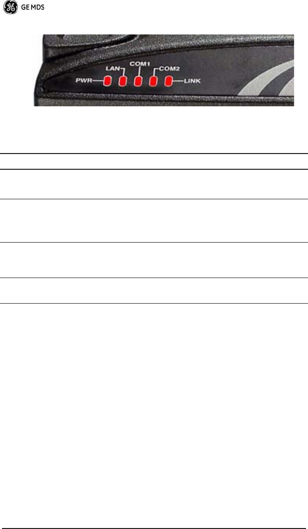
LED Indicators
The LED status indicators (Figure 7) are an important troubleshooting
aid and should be checked whenever a problem is suspected. Table 3
describes the function of each status LED on the top panel of the radio.
In addition to the top panel LEDs, the
ETHERNET/LAN
connector has
two integrated LEDs. A steady green LED indicates that an Ethernet
link has been established, a flashing green indicates data activity, and
a yellow LED indicates 100 Mbps operation.
STAT
Display radio status and alarms.
TEMP
Display the internal temperature of the radio
in degrees C.
TX [xxx.xxxx]
Set or display the transmit frequency.
Table 2. Command Summary
(Cont’d)
Command Name Function
10 MDS SD9 Startup Guide 05-xxxxA01, Rev. 01
Invisible place holder
Figure 7. LED Indicators
Event Codes
When an alarm condition exists, the transceiver creates a code that can
be read on a connected terminal. These codes can be helpful in
resolving many system difficulties. Refer to Table 4 (Page 11) for a
definition of the event codes.
Checking for Alarms
—STAT command
To check for alarms, connect a terminal to the radio’s
COM1
(diagnos-
tics) connector. See “COM1 CONNECTIONS” on Page 12 for pinout
information.
Enter
STAT
on the connected terminal. If no alarms exist, the message
NO ALARMS PRESENT appears on the display.
If an alarm does exist, a two-digit alarm code (00–31) is displayed and
the event is identified as a Major or Minor Alarm. A brief description
of the alarm is also given.
Table 3. LED Status Indicators
LED Name Description
PWR • Continuous—Power applied, no problems detected.
• Rapid flash (5 times-per-second)—Alarm indication.
LAN • Continuous—Local area network detected.
• Flashing—Data is being transmitted and received.
• Off—LAN not detected or excessive traffic is present.
COM1/COM2 The COM LEDs show activity on the serial payload data
port(s). The left LED shows TX data and the right one
shows RX data.
LINK When lit, indicates that a communication link is established
with the master station.

05-xxxxA01, Rev. 01 MDS SD9 Startup Guide 11
If more than one alarm exists, the word MORE appears on the screen.
To view additional alarms, press .
Major Alarms vs. Minor Alarms
Major Alarms—report serious conditions that generally indicate a
hardware failure, or other abnormal condition that will prevent (or
seriously hamper) further operation of the transceiver. Major alarms
generally indicate the need for factory repair. Contact your factory
representative for assistance.
Minor Alarms—report conditions that, under most circumstances will
not prevent transceiver operation. This includes out-of-tolerance con-
ditions, baud rate mismatches, etc. The cause of these alarms should
be investigated and corrected to prevent system failure.
Event Code Definitions
Table 4 contains a listing of event codes that may be reported by the
transceiver. The codes shown are a subset of a larger pool of codes
used for various GE MDS products. For this reason, the table does not
show a sequential listing of all code numbers. Only the codes appli-
cable to this product are shown.
Table 4. Event Codes
Event
Code
Event
Class Description
01 Major Improper software detected for this radio model.
04 Major The RF synthesizer is reporting an out-of-lock
condition.
08 Major The system is reporting that it has not been
calibrated. Factory calibration is required for proper
radio operation.
12 Major Receiver time-out. No data received within the
specified receiver time-out time.
13 Minor A Transmitter timeout was detected. The radio
stayed keyed longer than the duration specified by
the TOT command.
17 Minor A data parity fault has been detected on the COM2
INTERFACE connector. This usually indicates a
parity setting mismatch between the radio and the
RTU.
ENTER

12 MDS SD9 Startup Guide 05-xxxxA01, Rev. 01
Internal Spectrum Analyzer
The radio contains a built-in spectrum analyzer tool that can be dis-
played on a connected PC. The tool is helpful in diagnosing interfer-
ence problems on or near your channel frequency.
Access the spectrum analyzer by entering spectrum at the command
prompt. A display appears showing detected signals on your current
channel.
Optionally, you can specify a frequency at the command prompt to
view the surrounding spectrum of that frequency. To do this, enter
spectrum xxx.xx, where xxx.xx is the frequency in MHz.
The display creates a received signal strength indication (RSSI) vs.
frequency plot for the frequency and surrounding signals. By ana-
lyzing the display, you can determine the presence of other signals
near the transceiver’s operating frequency. This information can be
helpful in troubleshooting interference problems.
COM1/COM2 REFERENCE
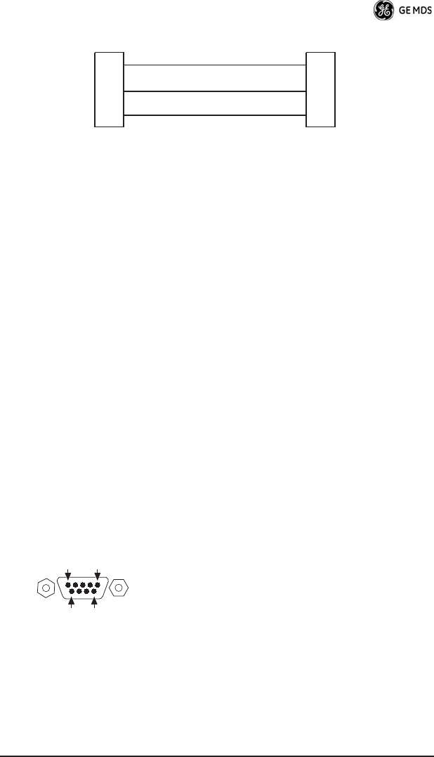
COM1 CONNECTIONS
The COM1 connector is used to connect a PC to the radio for manage-
ment or diagnostics. A straight-through cable is required that connects
Pin 2 (RXD), Pin 3 (TXD), and Pin 5 (Ground). (See Figure 8.)
18 Minor A data framing error has been detected on the
COM2 INTERFACE connector. This may indicate a
baud rate mismatch between the radio and the RTU.
26 Minor The DC input voltage is out-of-tolerance. If the
voltage is too far out of tolerance, operation may fail.
31 Minor The transceiver’s internal temperature is
approaching an out-of-tolerance condition. If the
temperature drifts outside of the recommended
operating range, system operation may fail.
Table 4. Event Codes (Cont’d)
Event
Code
Event
Class Description
05-xxxxA01, Rev. 01 MDS SD9 Startup Guide 13
Invisible place holder
Figure 8. COM1 Wiring to Computer
NOTE: To prevent unintended keying of the transmitter during
management activities, set PTTSIG to OFF, or do not
connect to Pin 6 of the COM1 port.
COM2 CONNECTIONS
The COM2 connector (Figure 9) is used to connect the radio to an
external DTE telemetry device that supports the EIA/RS-232 or
EIA/RS-485 (balanced) format, depending on how the radio is config-
ured. The radio supports data rates of 300, 1200, 2400, 4800, 9600,
19200, 38400, 57600, and 115200 bps (asynchronous data only).
The COM2 connector mates with a standard DB-9 plug that is avail-
able from many electronics parts distributors. Table 5 provides
detailed pin descriptions for the COM2 data connector in RS/EIA-232
mode.
NOTE:To prevent unintended keying of the transmitter on RTS, set
RTSKEY to OFF, or do not connect to Pin 7 (RTS) of the COM2 port.
Pin Descriptions—RS/EIA-232 Mode
Table 5 lists the COM connector pin functions when configured to
operate in RS/EIA-232 mode. For RS/EIA-422/485 mode, refer to the
Reference Manual.
Figure 9. COM2 Connector (DB-9F)
As viewed from outside the radio
RXD
TXD
GND
2
3
5
RXD
TXD
GND
2
3
5
>
<
DB-9 FEMALE
(COMPUTER)
DB-9 MALE
(RADIO SIDE)
5
96
1

14 MDS SD9 Startup Guide 05-xxxxA01, Rev. 01
NOTE: The radio is hard-wired as a DCE device.
NOTE: Additional information on Analog Mode operation (including
cable wiring details) is contained in the Reference Manual.
Table 5. COM2 Pin Descriptions—RS/EIA-232
Pin
Number
Input/
Output Pin Description
1 OUT DCD (Data Carrier Detect/Link)—A low indicates
signal received.
Digital Modem Selections: Digital carrier detect
Analog Modem Selections: Squelch indicator
2 OUT RXD (Received Data)—Supplies received data to
the connected device.
3INTXD (Transmitted Data)—Accepts TX data from the
connected device.
4INSleep Mode Input—Grounding this pin turns off
most circuits in a remote radio. This allows for greatly
reduced power consumption, yet preserves the
radio’s ability to be quickly brought on line. (See
Using the Radio’s Sleep Mode” for details.)
5--Signal Ground—Connects to ground (negative
supply potential) on chassis.
6 OUT Alarm Output (DSR)—An RS-232 high/space
(+5.0 Vdc) on this pin indicates an alarm condition.
An RS-232 low/mark (–5.0 Vdc) indicates normal
operation. This pin may be used as an alarm output.
(See Reference Manual.)
7INRTS (Request-to-Send)—Keys the transmitter.
8 OUT CTS (Clear-to-Send)—Goes “high” after the
programmed CTS delay time has elapsed (DCE), or
keys an attached radio when RF data arrives (CTS
KEY).
9 -- Reserved—User I/O for special applications

05-xxxxA01, Rev. 01 MDS SD9 Startup Guide 15
SPECIFICATIONS
GENERAL
Frequency Range*: MDS SD9: 920–960 MHz
* Specific frequency authorizations are dependent on the type-approval of
radio. Consult the factory for details.
RECEIVER
Maximum Usable Sensitivity: –110 dBm at 1x10⁻⁶ BER (Preliminary)
Bandwidth: 12.5, 25 kHz
TRANSMITTER
Carrier Power: 0.1 Watts to 5 Watts
Duty Cycle: Continuous
Output Impedance: 50 Ω
Channel Spacing: 12.5, 25 kHz
FCC Emission Designators:
12.5 kHz B/W: 10K6F1D, F2D, F3D
25.0 kHz B/W: 16K2F1D, F2D, F3D
DATA CHARACTERISTICS
Signaling Type: EIA/RS-232; DB-9 Female connector
COM2 Data Rates: 300–115200 bps, asynchronous
Data Latency: 10 ms maximum
PRIMARY POWER
Voltage: 13.8 Vdc Nominal (10.5 to 30Vdc)
Negative-Ground Systems Only
TX Supply Current: 2.0 Amperes (Typical) @ 5 Watts RF
Output
RX Supply Current: Operational—125 mA, Nominal
Fuse: 5-Ampere, internal
ENVIRONMENTAL
Humidity: 95% at 40 degrees C (104°F),
non-condensing
Temperature Range: –40 to 70 degrees C (–40°F to +158°F)
Weight: 1.0 kilograms

16 MDS SD9 Startup Guide 05-xxxxA01, Rev. 01
DIAGNOSTICS INTERFACE
Signaling Standard: RS-232 (COM1)
RS-232/RS-485 (COM2)
Connector: COM1—DB-9F
COM2—DB-9F
Specifications are subject to change without notice or obligation.

Installation Guide

GE MDS, LLC
Rochester, NY 14620
General Business: +1 585 242-9600
FAX: +1 585 242-9620
Web: www.GEmds.com
175 Science Parkway