GE MDS DS-SDM4 MDS SDM4 Licensed Spectrum Module User Manual
GE MDS LLC MDS SDM4 Licensed Spectrum Module Users Manual
UserManual.wiki
>
GE MDS
>
DS SDM4 User Manual
Users Manual
Navigation menu
Upload a User Manual
Namespaces
Wiki Guide
HTML
PDF
Info
Views
User Manual
Discussion / Help
Navigation
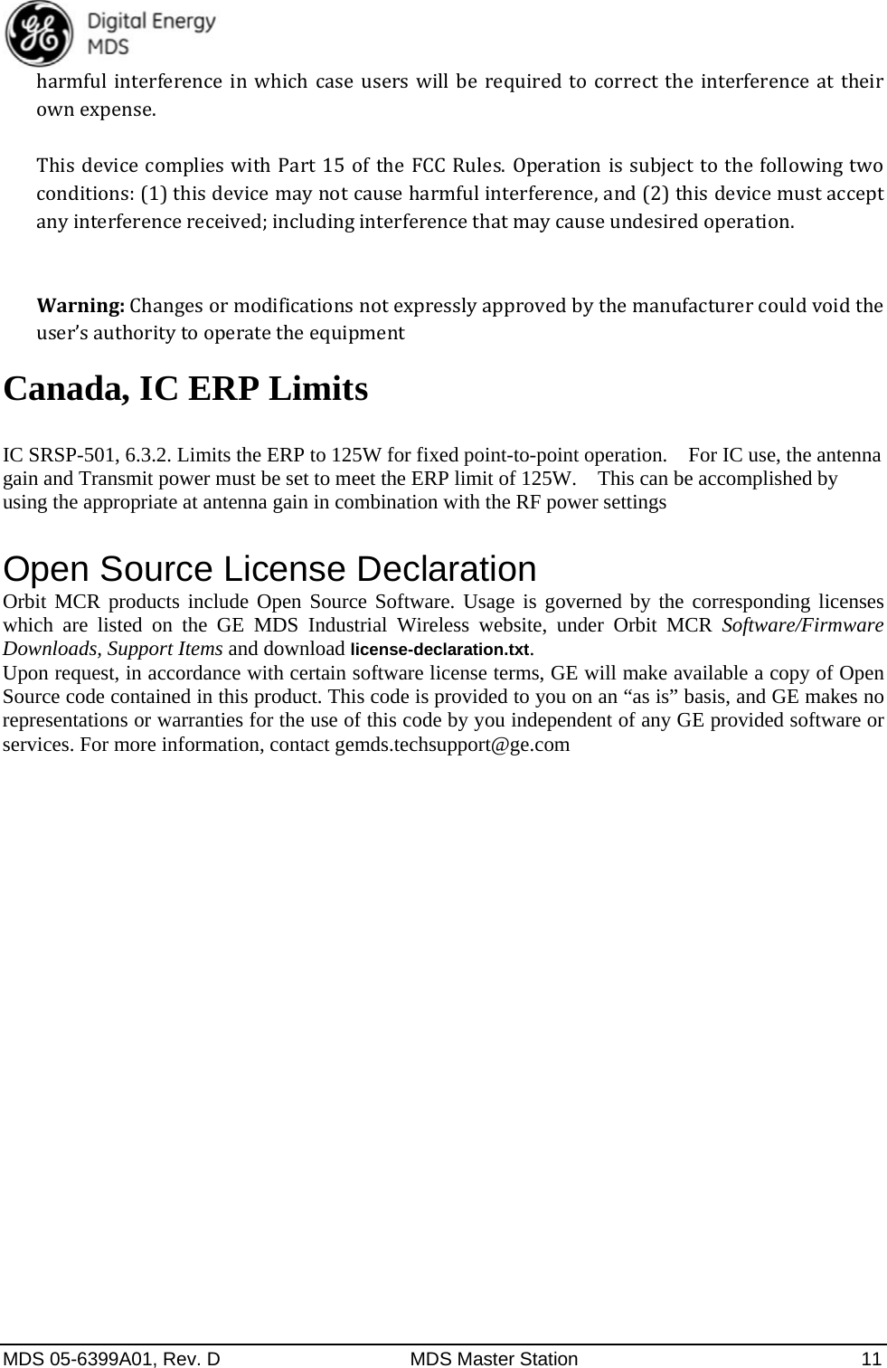
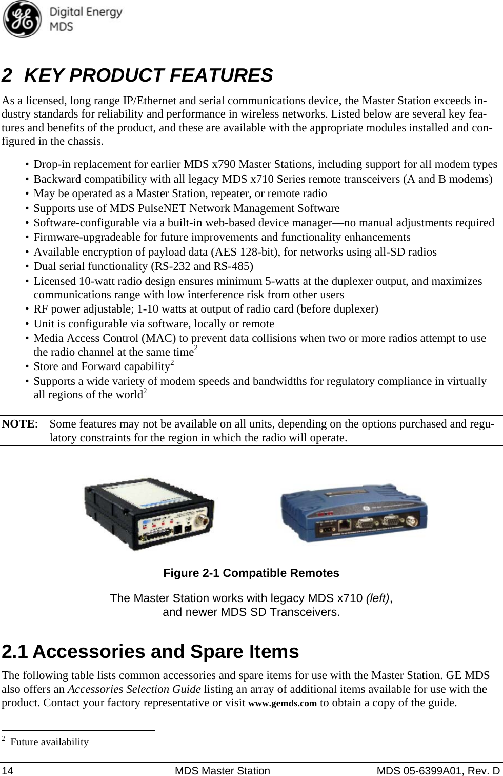
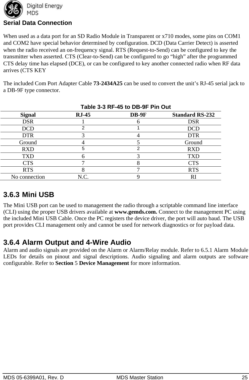
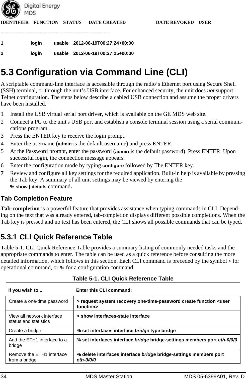
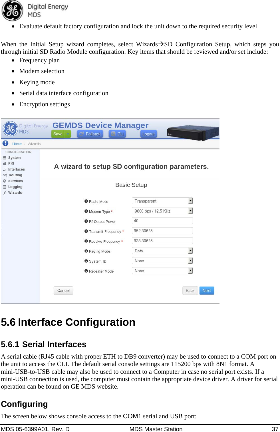
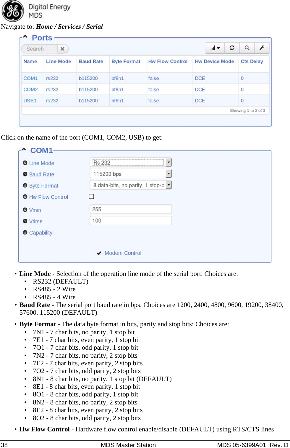
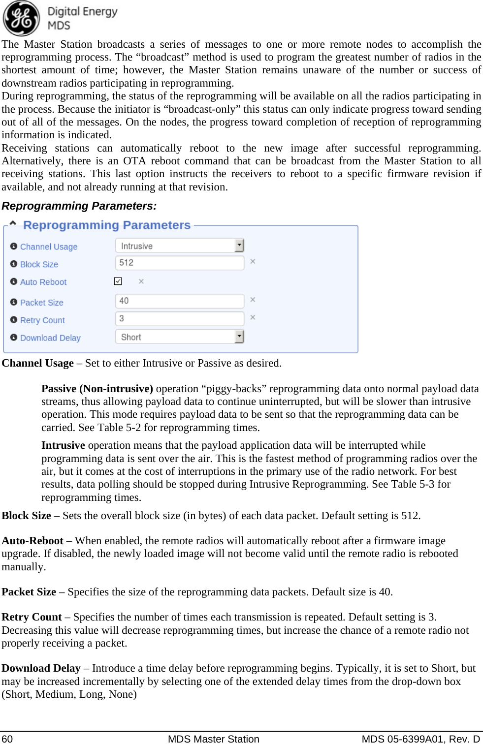
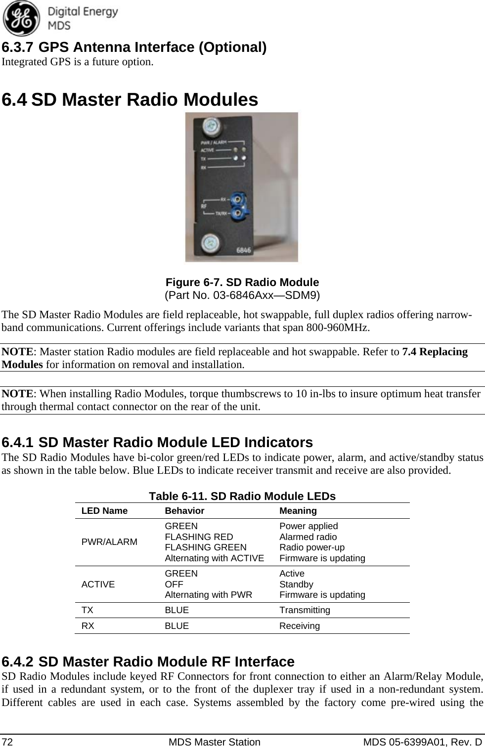
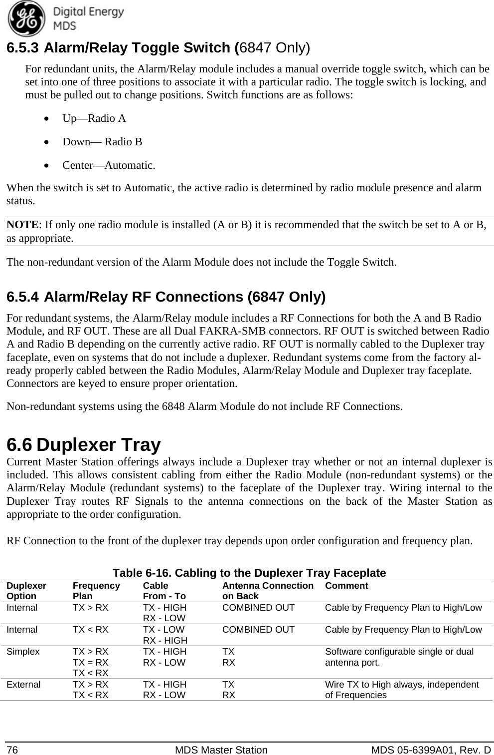
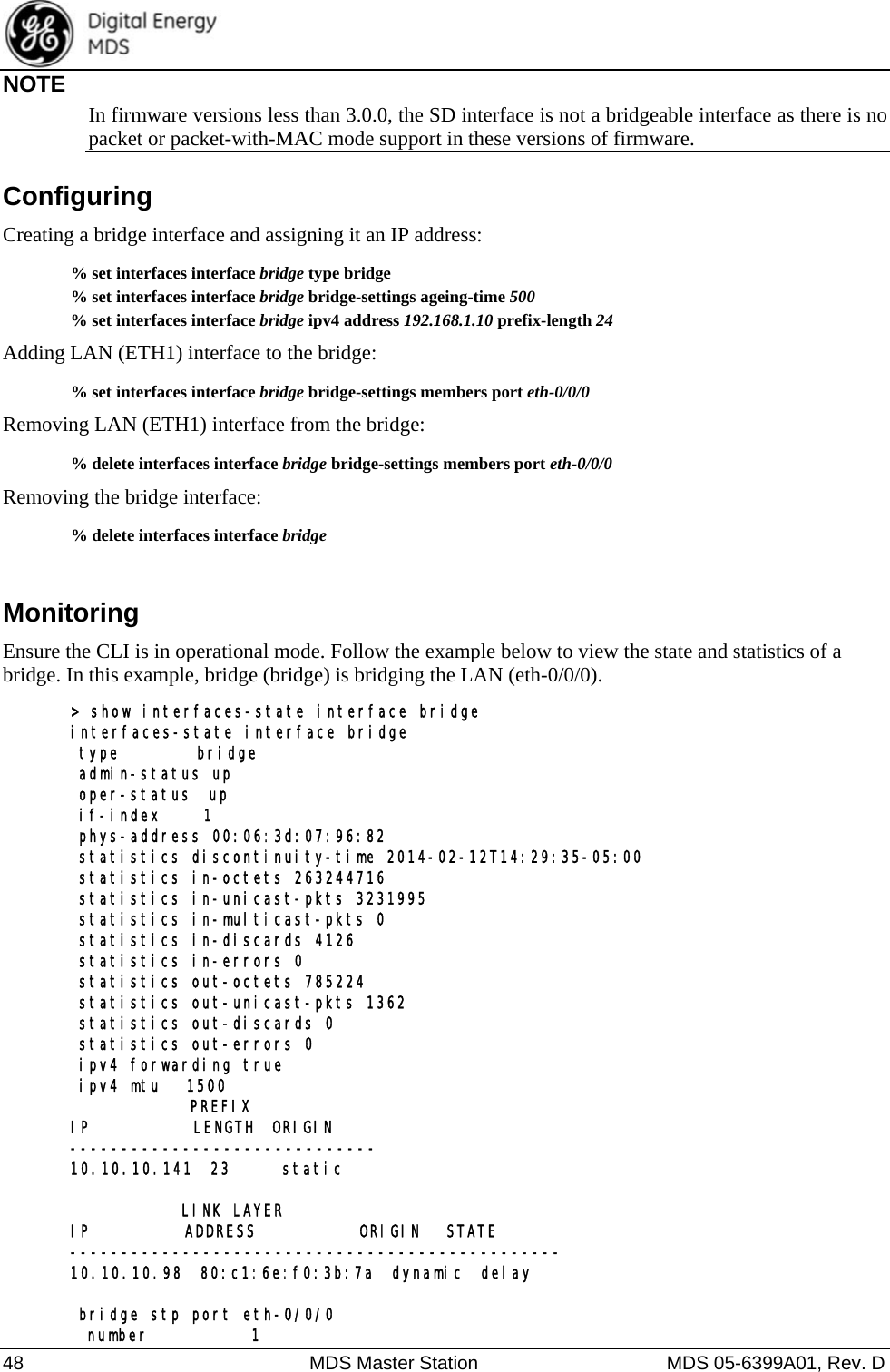
![40 MDS Master Station MDS 05-6399A01, Rev. D • After the last character of a transmission is output from the serial port, the unit shall keep CTS as-serted until the expiration of CTS hold time. 3. CTSKEYPLUS • The unit shall support flow control (Throttling) on the RTS pin. The device is expected to be wired via null modem to an external DCE device. The CTS line of the external DCE device drives the RTS line of the unit. Monitoring From the Web UI. the Serial Ports screen shows the settings: Navigate to: Home / Services / Serial From the CLI in operational mode, follow the example below to view the state and statistics: > show configuration services serial | details ports COM1 { line-mode rs232; baud-rate b115200; byte-format bf8n1; hw-flow-control false; vmin 255; vtime 1; capability rs485-2-wire,rs485-4-wire; } ports COM2 { line-mode rs232; baud-rate b19200; byte-format bf8n1; hw-flow-control false; vmin 255; vtime 1; capability ""; } console { serial-ports [ COM1 COM2 ]; }](https://usermanual.wiki/GE-MDS/DS-SDM4/User-Guide-2722876-Page-40.png)
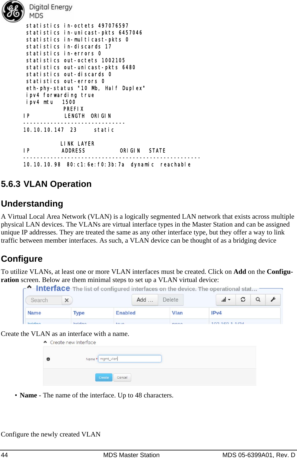
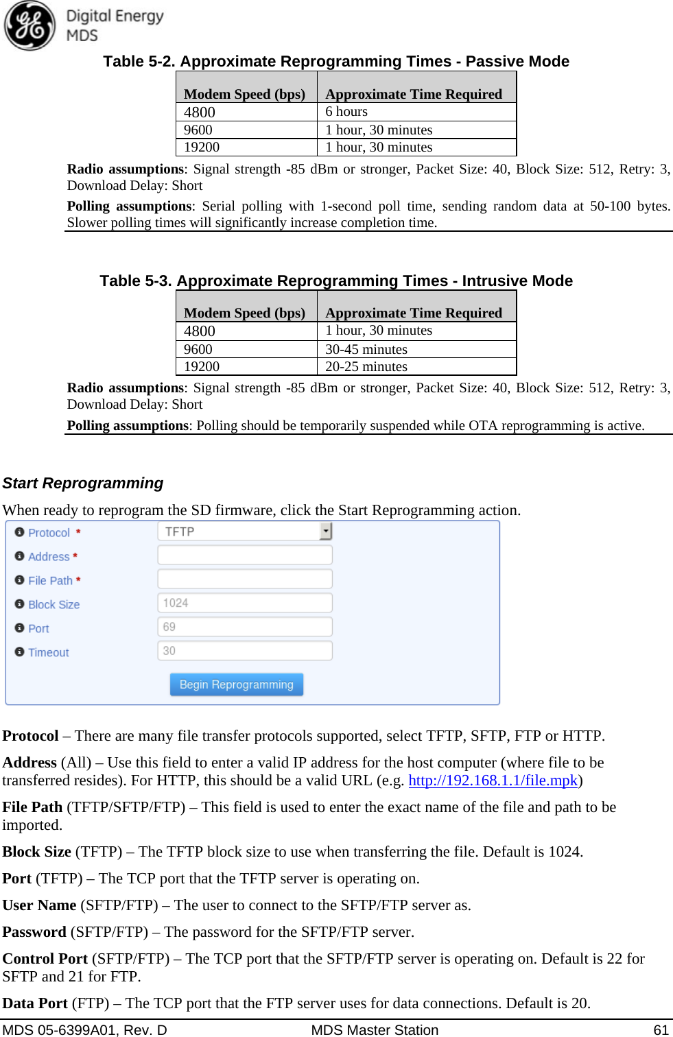
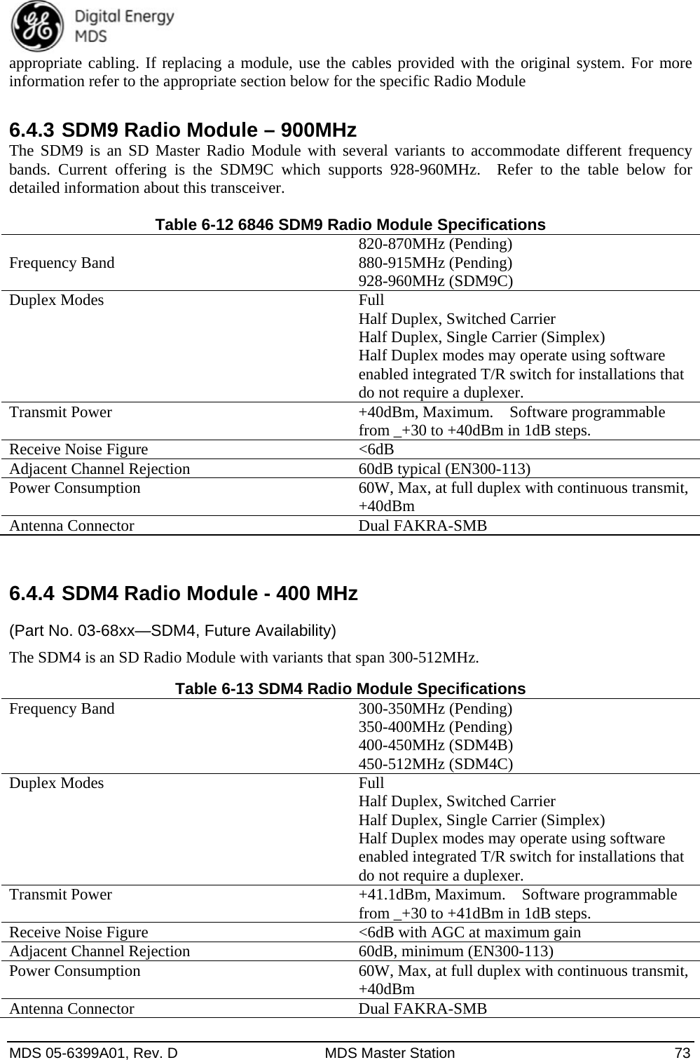
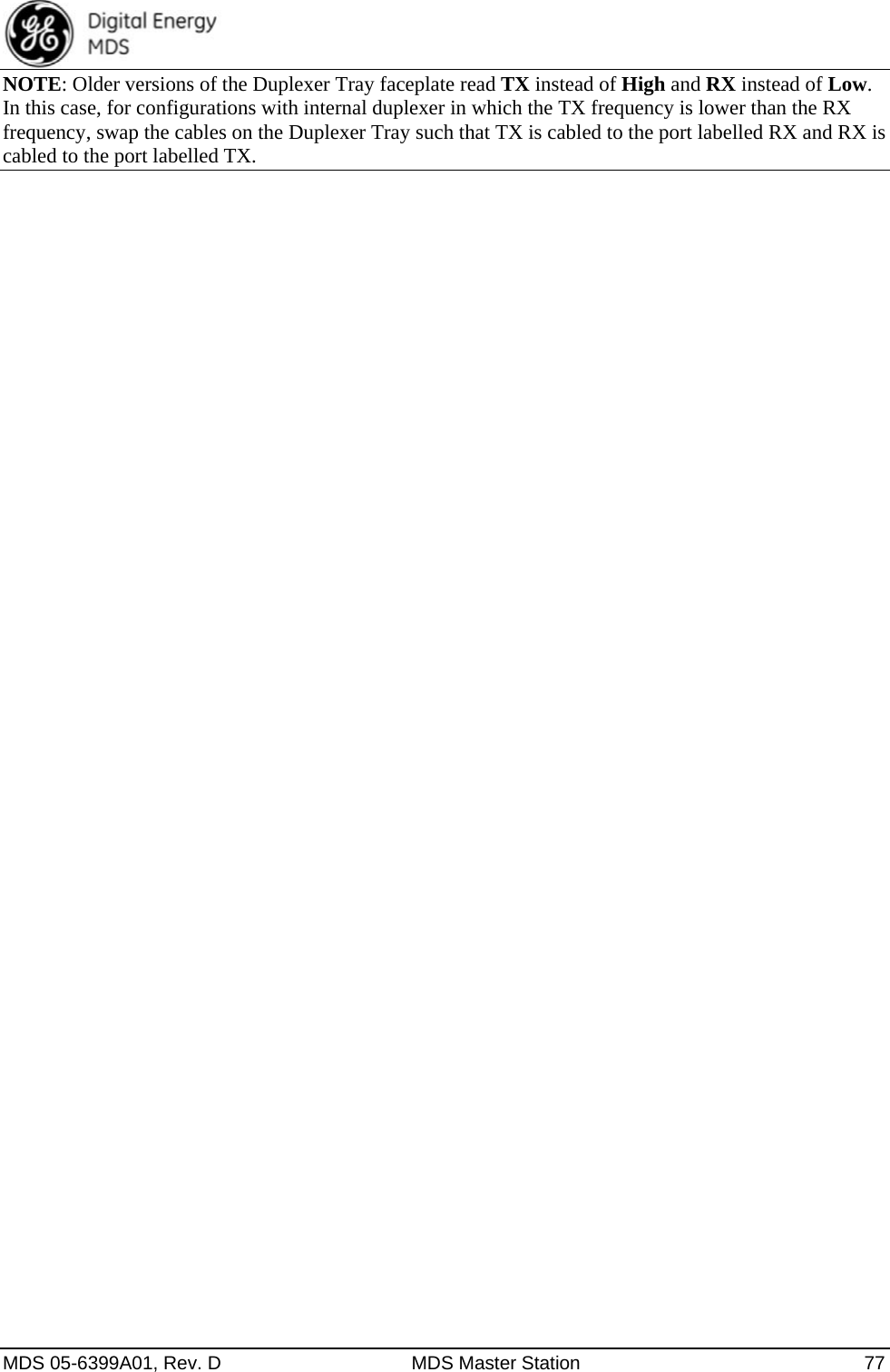
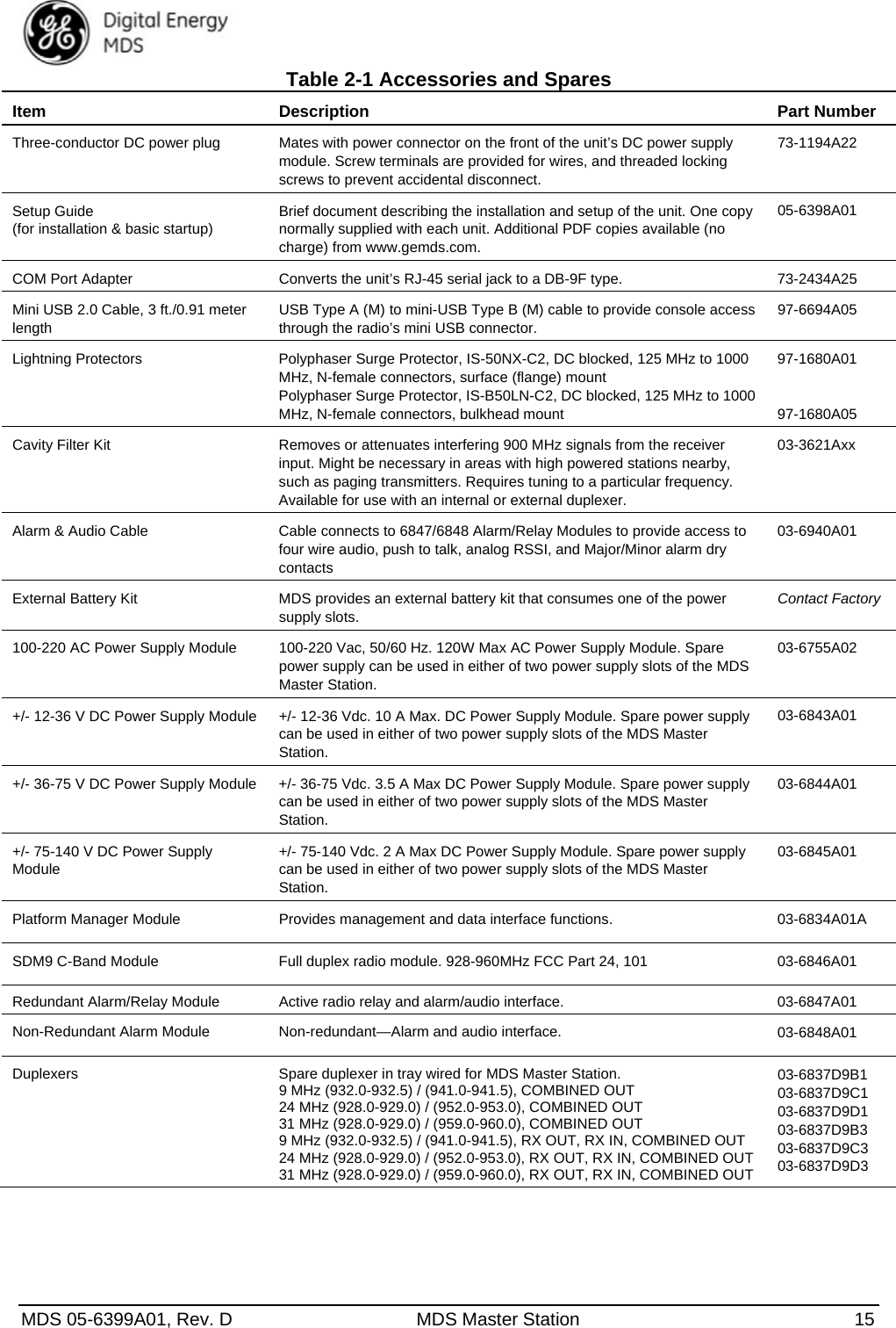
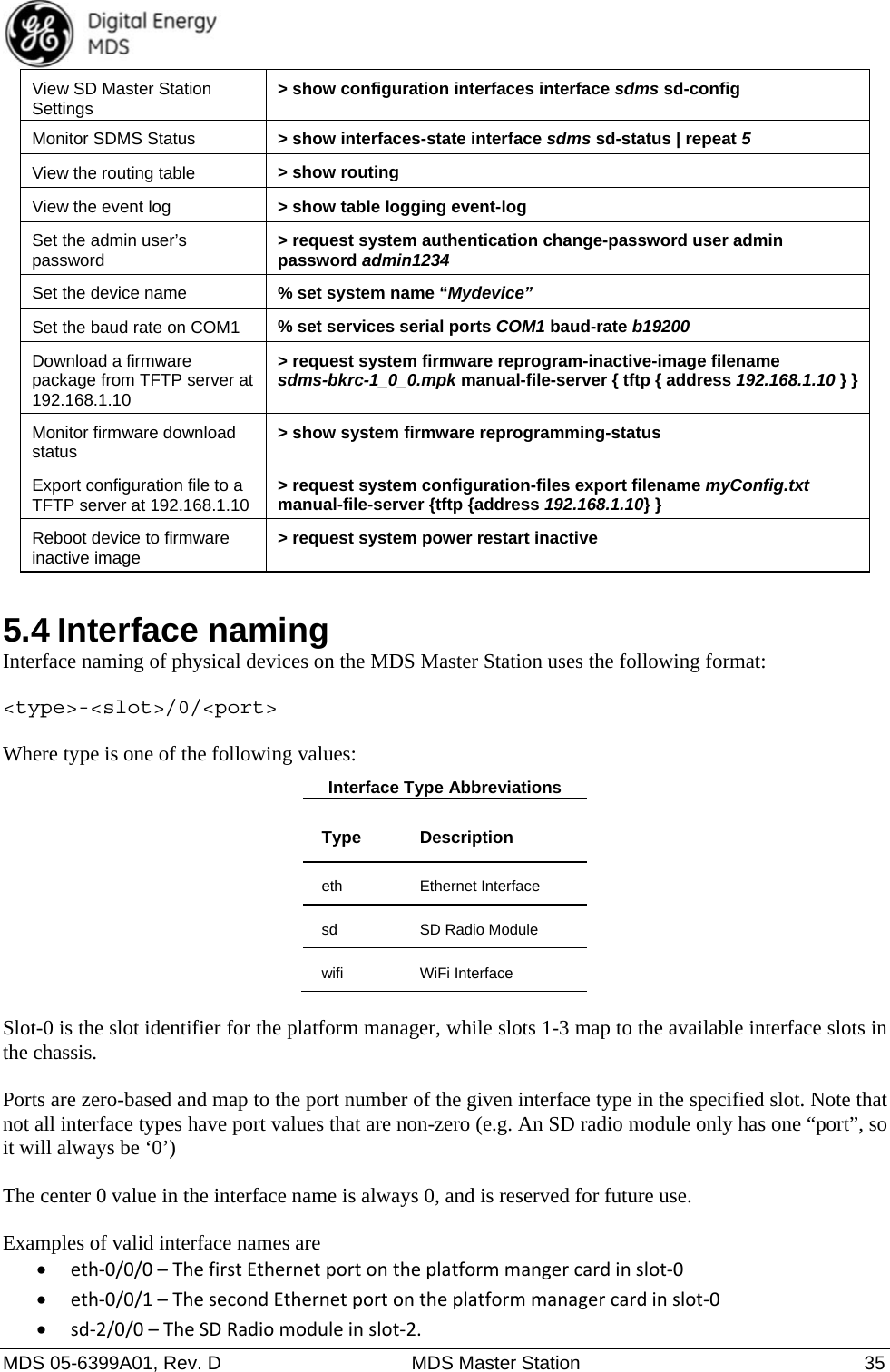
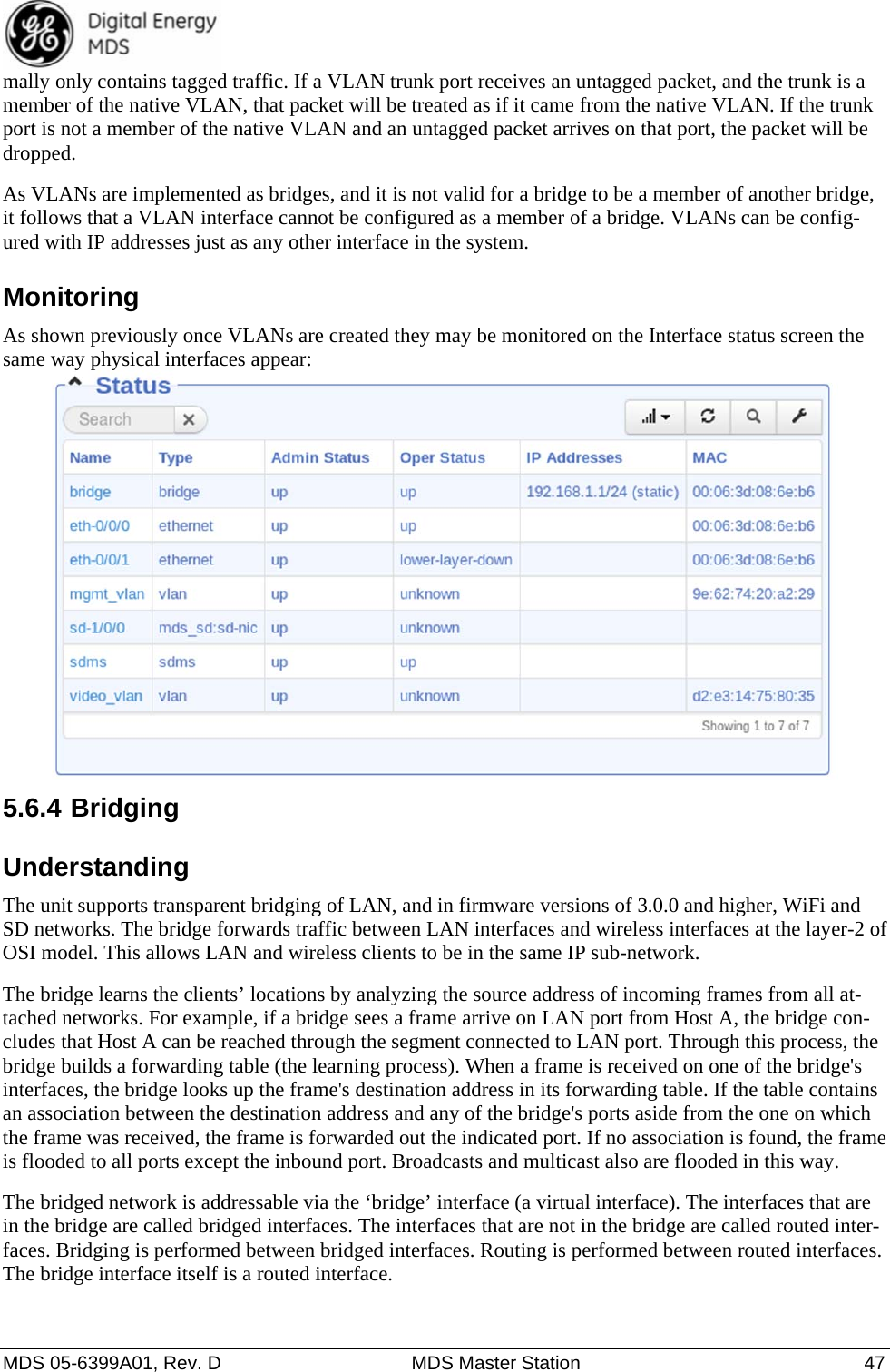
![46 MDS Master Station MDS 05-6399A01, Rev. D Using the CLI to set up a VLAN, four sample commands are shown below for doing this; one with an ID of 99 and another with an ID of 300: % set interfaces interface mgmt_vlan type vlan % set interfaces interface mgmt_vlan vlan-config vlan-id 99 % set interfaces interface video_vlan type vlan % set interfaces interface video_vlan vlan-config vlan-id 300 Operational Modes As previously shown in previous sections, interfaces can have three separate VLAN modes: none (de-fault), trunk, or access. These modes are used to set interface behavior, and examples of their use are pro-vided below. Trunk: To add ETH1 as a trunk (tagged) port in both defined VLANs above, the command is: % set interfaces interface eth-0/0/0 vlan-mode trunk vlans [ video_vlan mgmt_vlan ] Access: To set ETH2 as an access port for video_vlan the command is: % set interfaces interface eth-0/0/1 vlan-mode access vlan video_vlan Native VLANs A VLAN device may also be specified as a “native” VLAN by checking the Native Vlan box. Or, using the CLI with this set command: % set interfaces interface my_native_vlan type vlan vlan-config vlan-id 99 native-vlan true A native VLAN is conceptually the same as a standard VLAN except that the packets will never be tagged. The purpose of a native VLAN is to segregate untagged packets on a VLAN trunk port that nor-](https://usermanual.wiki/GE-MDS/DS-SDM4/User-Guide-2722876-Page-46.png)
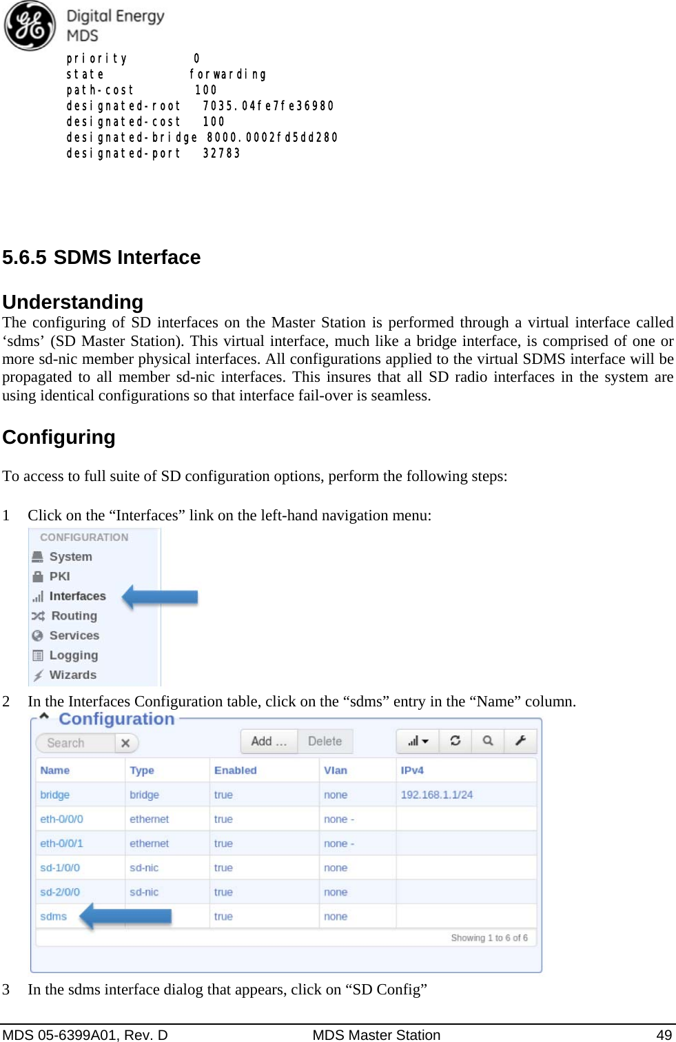
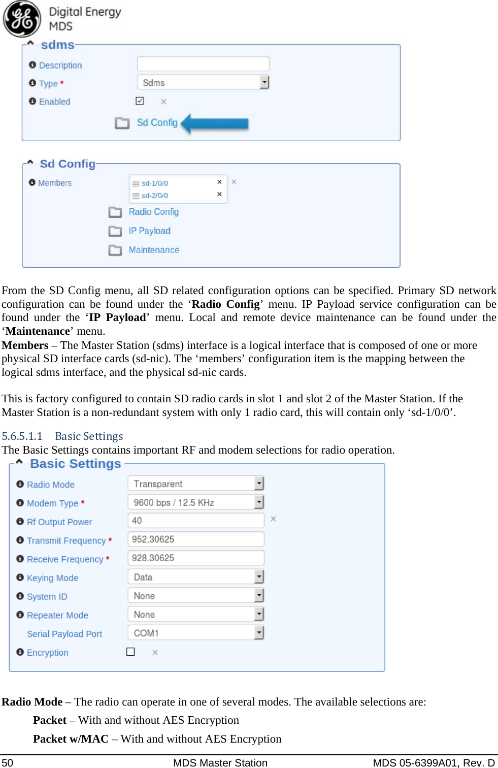
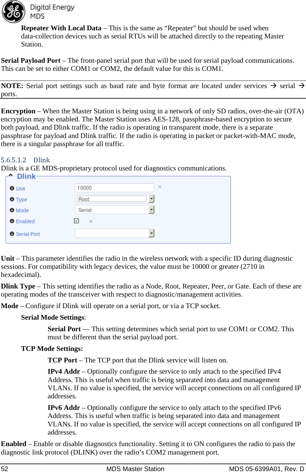
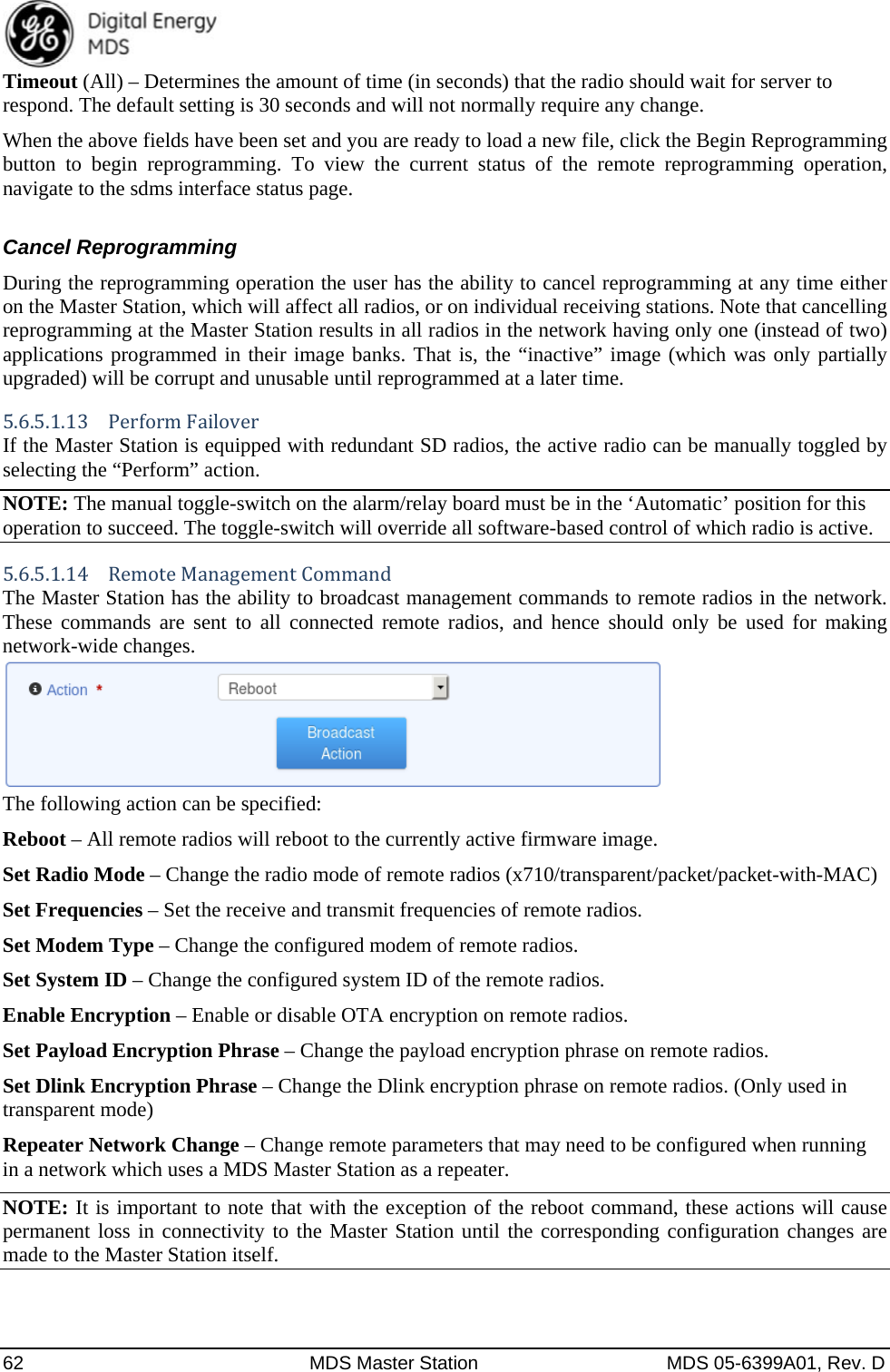
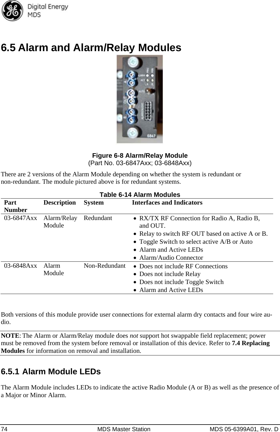
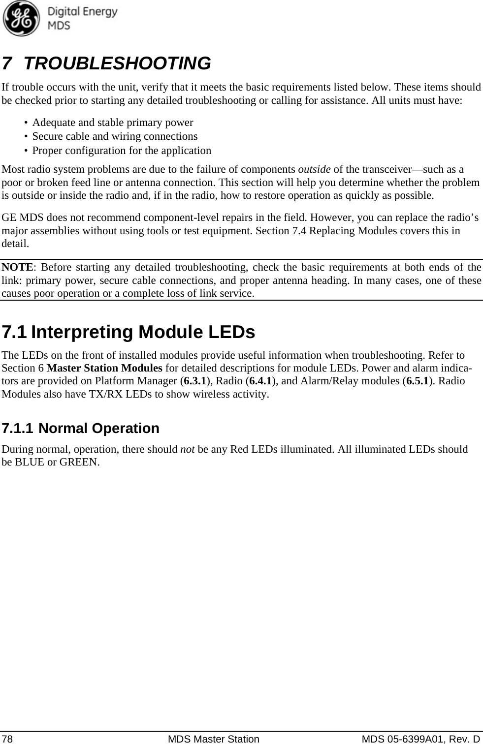
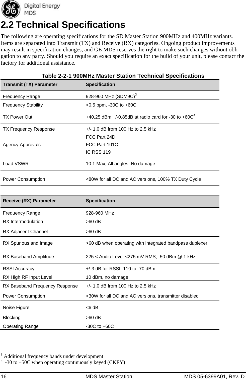
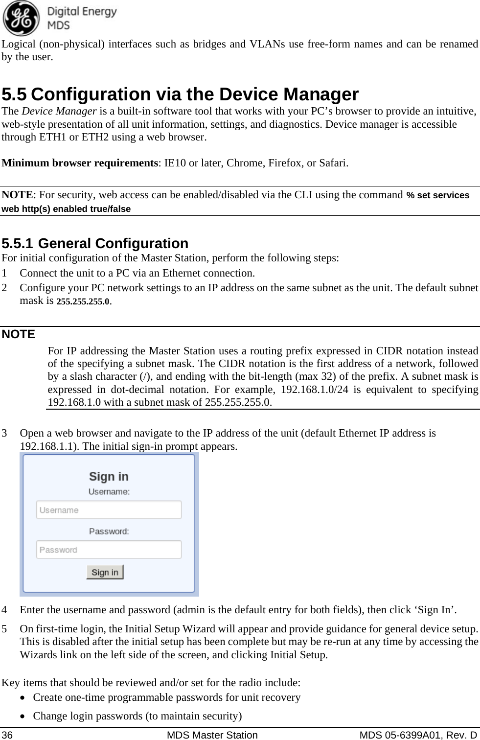
![MDS 05-6399A01, Rev. D MDS Master Station 51 x710 – When using the Master Station in a legacy x710 network. Transparent – With and without AES Encryption. (Transparent w/AES Encryption requires an all SD radio network.) RF Output Power (dBm) – The RF output power may be set between 30 and 40 dBm (1 to 10 watts) in 1 dB increments. The default setting is 40dBm. This setting represents the output power at the Radio Card. Output power at the antenna port on the back of the unit will be less due to cable, switching, and duplexer losses. Full power is not required in many cases, and lower settings will place less demand on the power supply and reduce the chance of interference with other stations. Only the power necessary to carry out reliable communications should be used. Modem Type – This setting determines the over-the-air data speed and bandwidth of the radio’s transmitted signal. All radios in the network must use the same modem setting to communicate with each other. The default setting is Modem 9600, but it may be set to any of the selections shown in Error! Reference source not found.. The table also lists modem sensitivity ratings for the various modems. Note that some modem choices are limited based on the model purchased. Transmit/Receive Frequency – The receive and transmit frequencies may be viewed or set here. Transmit/Receive Frequency – The receive and transmit frequencies may be viewed or set here. Frequencies must be entered for the radio to operate. Consult your station license to determine the authorized frequencies for your system, and enter them exactly as listed. Keying Mode – Keying mode must be set to one of the following values: Data – Radio will key upon receipt of payload data. RTS – Radio will key upon receipt of an RTS (request to send) signal on the serial port. Note: RTS keying mode is only supported when the radio is in x710 mode. Data or RTS – Radio will key upon receipt of either payload data or an RTS (request to send) signal on the serial port. Continuous – Radio will be continuously keyed. This is primarily used in a transparent streaming repeater configuration. Note: Continuous keying mode is only supported in x710 mode, or in transparent mode when operating as a repeater. System ID – Provides the possibility for Frequency Re-use. System ID offers nine unique choices including the default value of NONE. The setting NONE is required for mixed networks comprised of MDS legacy and SDx products. SDx-only networks can utilize the Frequency Re-use feature by setting the System ID to a common value [1-8] for all radios in a specific network. System ID offers approximately 20 dB of additional co-channel isolation when operating networks on the same frequency. Note that proper system design is required. Operational Example: SDx System “Alpha” has eight units and SDx System “Beta” has eight units. A user wishes to occupy frequency 952.1235 MHz on both of these systems. Proper system installation has been adhered to in both networks. System Alpha’s units would all be set to System ID = 1, System Beta's units would be set to System ID = 5. Both systems will now operate on the same desired frequency. FCC Part 90 Repeater Mode – Repeater mode must be set to one of the following values: None – This is the default value, and is used when the Master Station being configured is not to be used as a repeater in the network. Repeater – This value should be selected when the Master Station being configured is to be installed as a repeater in the network, and will not have devices connected to it that will be polled, such as attached RTUs.](https://usermanual.wiki/GE-MDS/DS-SDM4/User-Guide-2722876-Page-51.png)