GE MDS DS-SERIES4 MDS Four.9 Series Digital Radio System User Manual Manual Rev 1
GE MDS LLC MDS Four.9 Series Digital Radio System Manual Rev 1
UserManual.wiki
>
GE MDS
>
DS SERIES4 User Manual
user manual
Navigation menu
Upload a User Manual
Namespaces
Wiki Guide
HTML
PDF
Info
Views
User Manual
Discussion / Help
Navigation

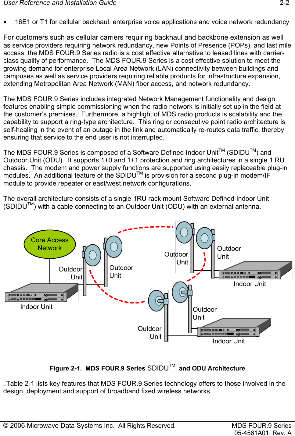
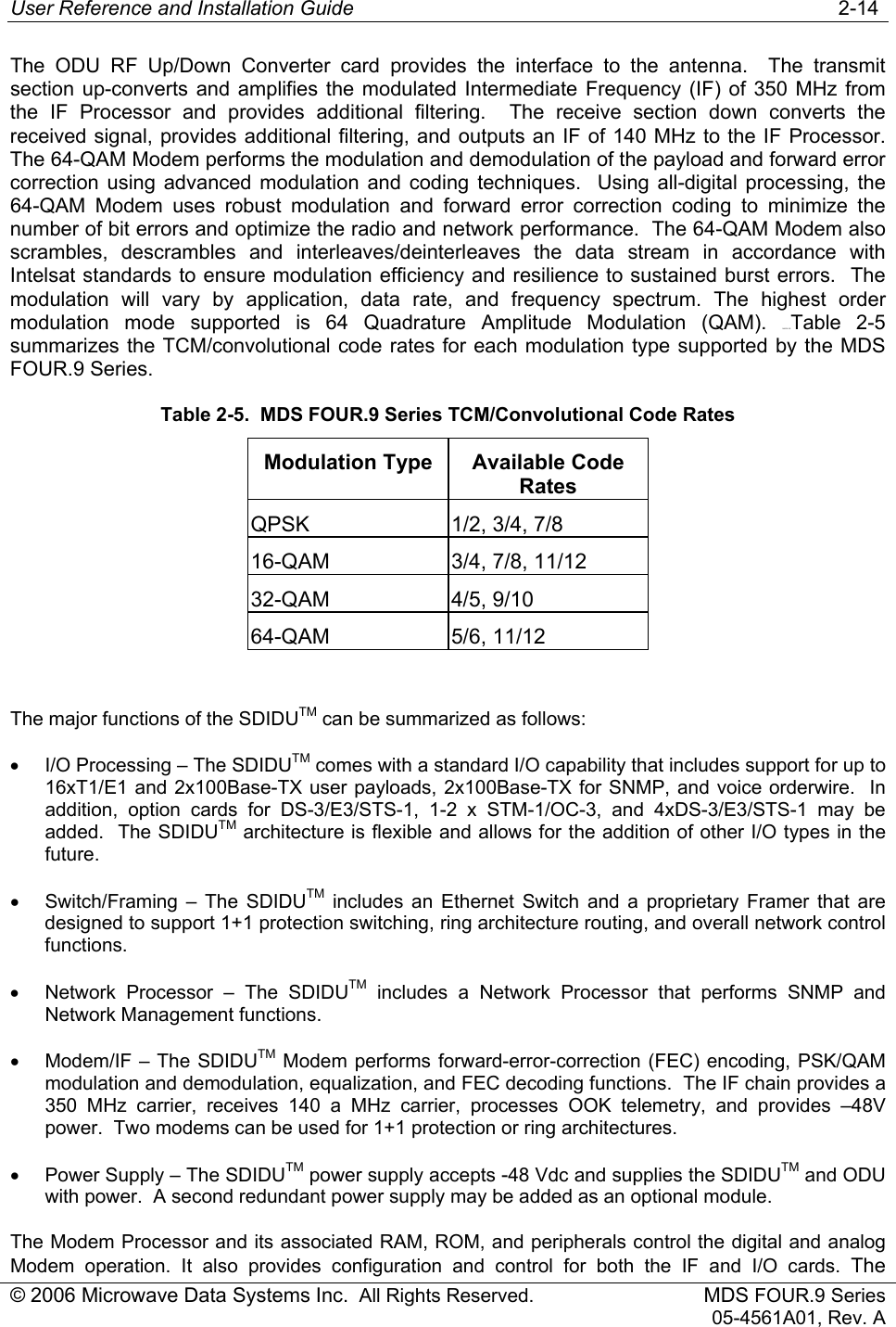
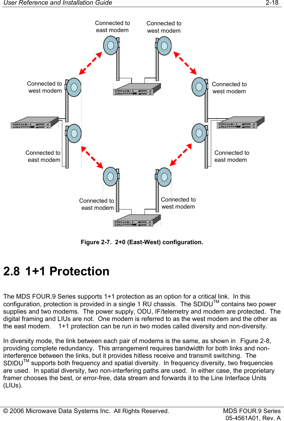
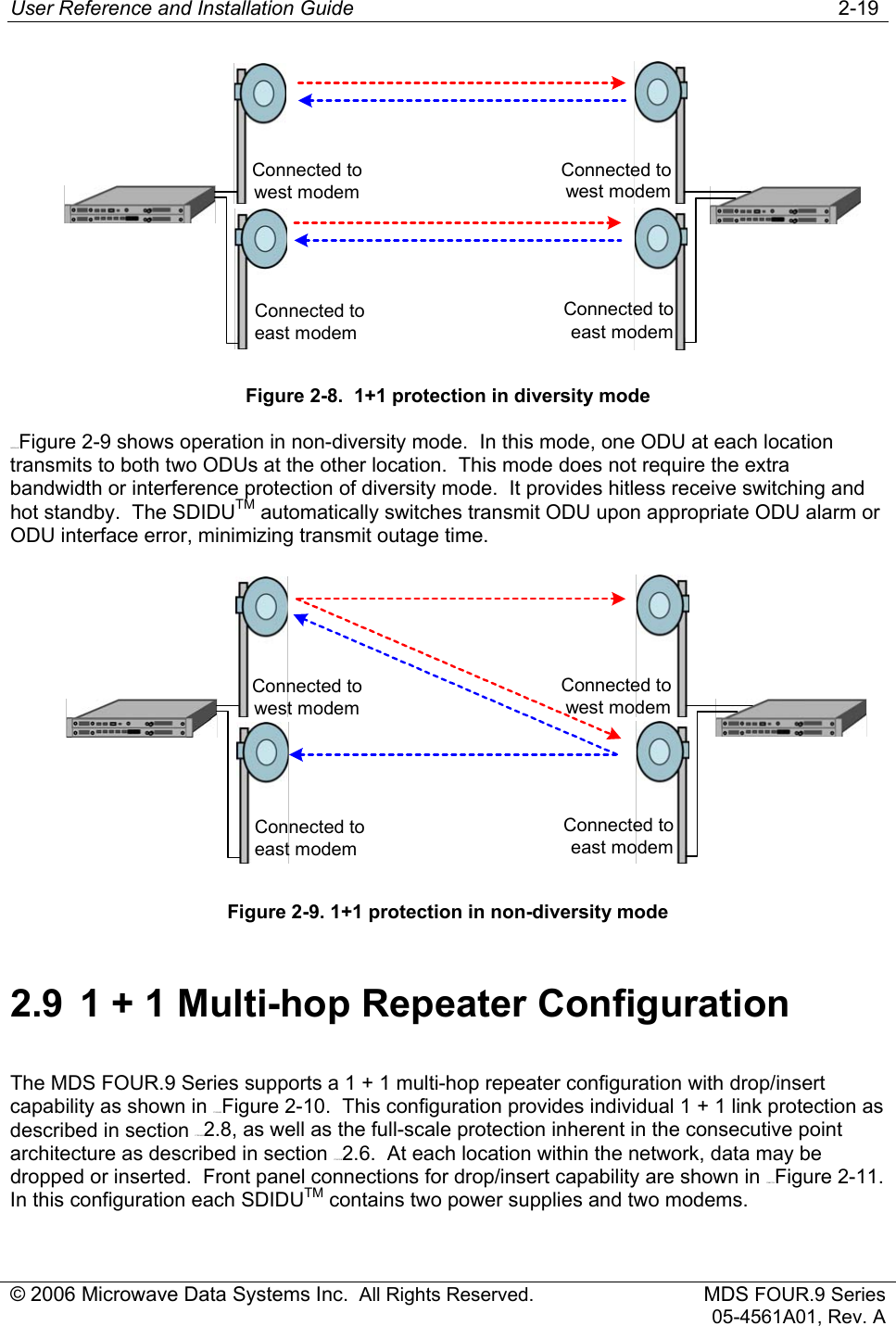
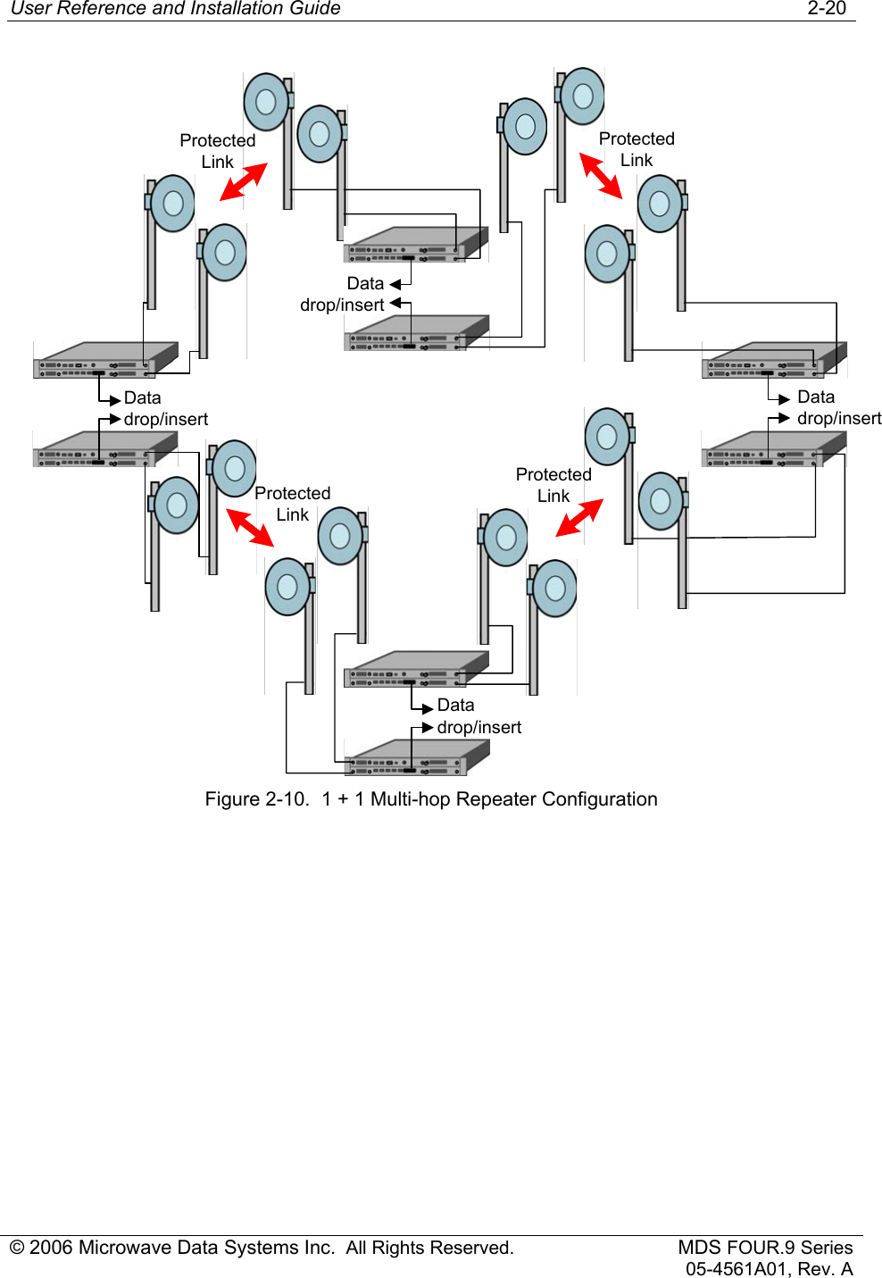
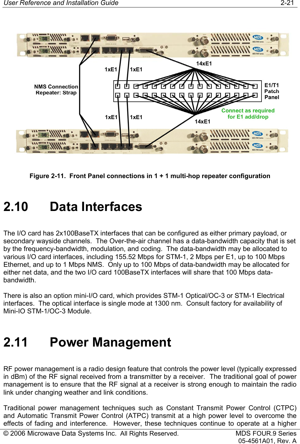
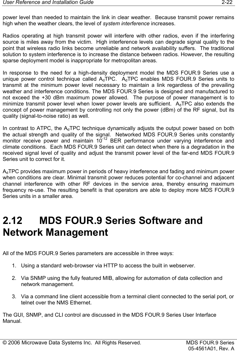
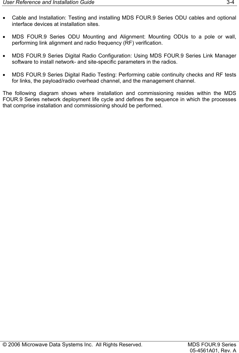
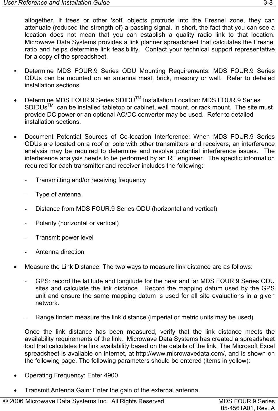
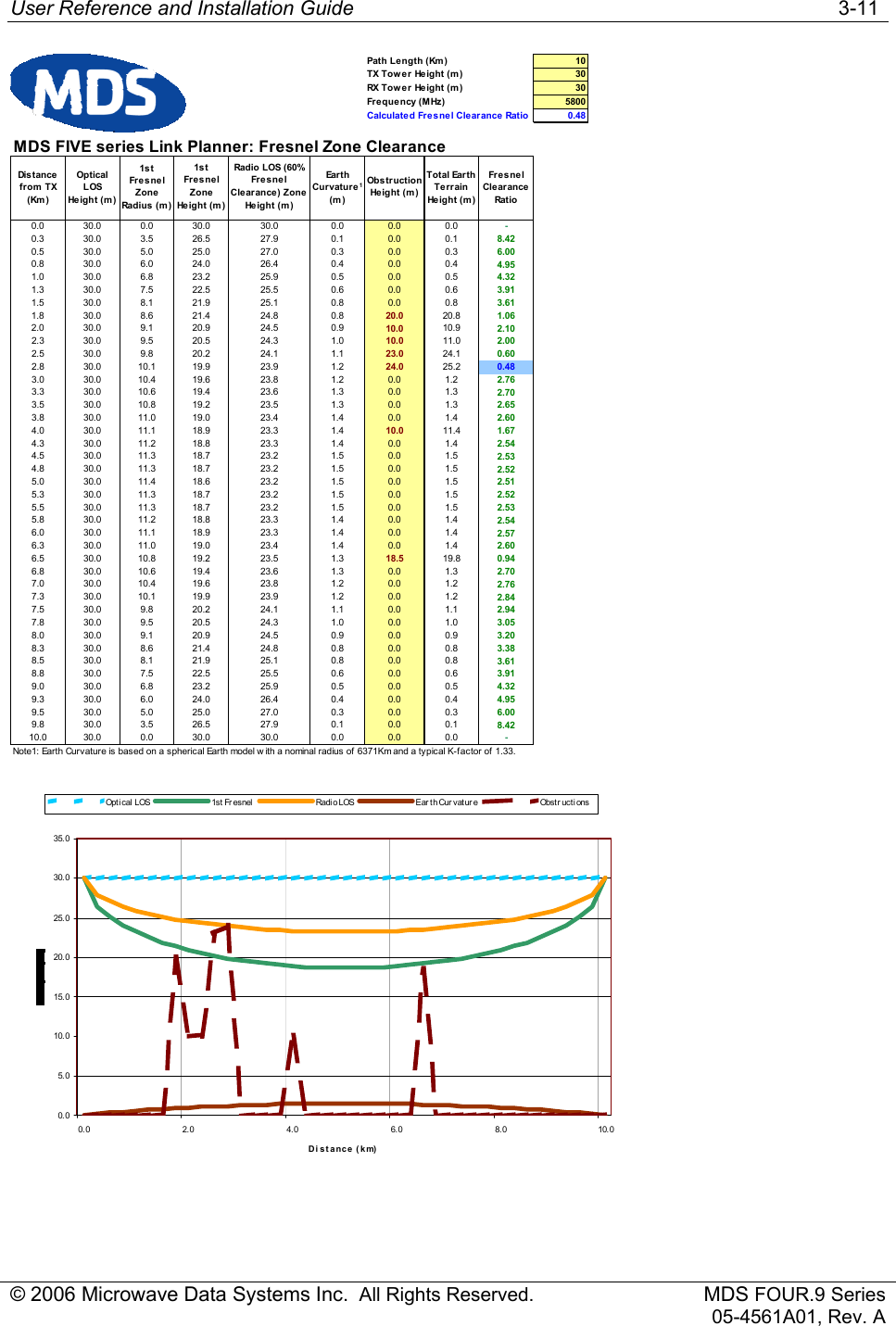
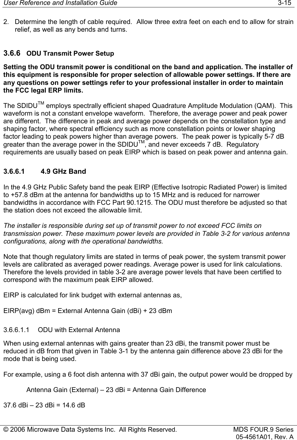
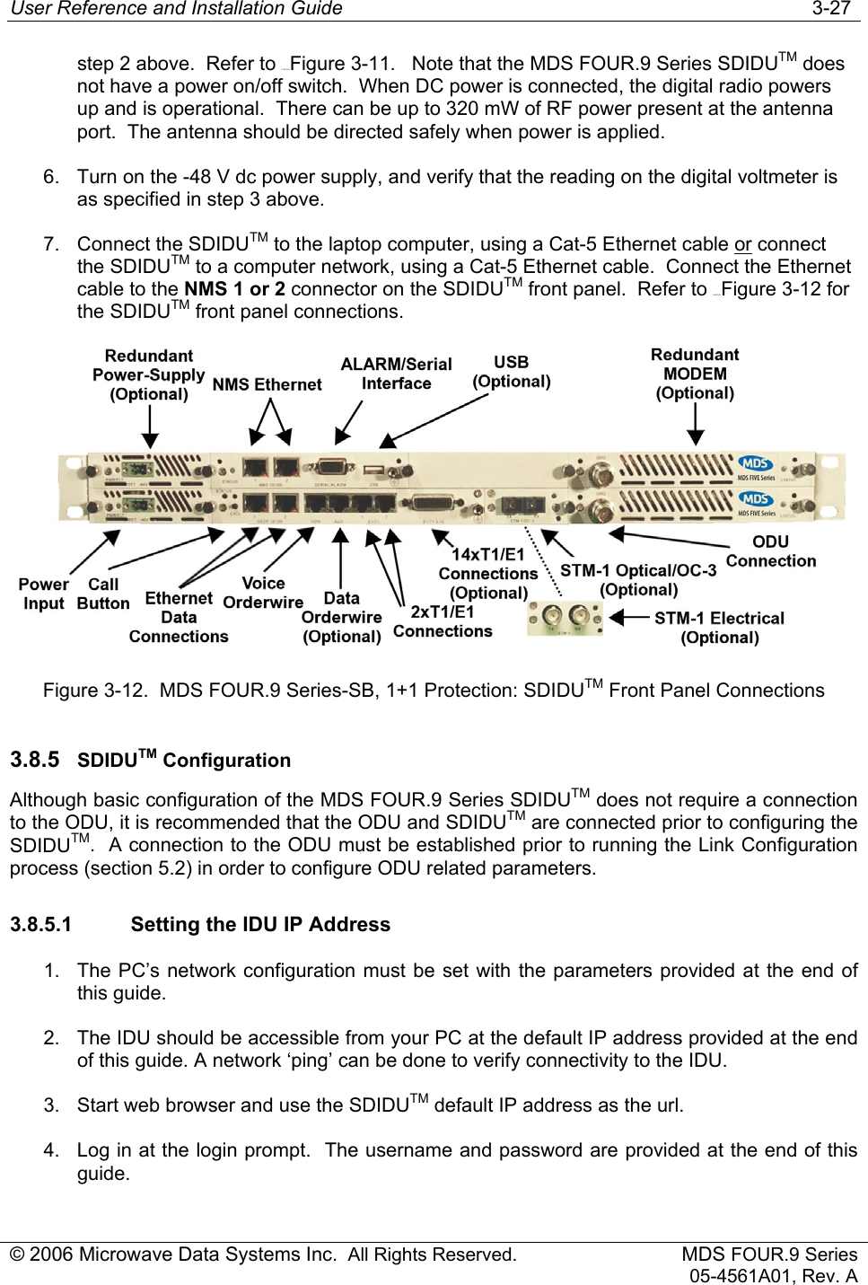
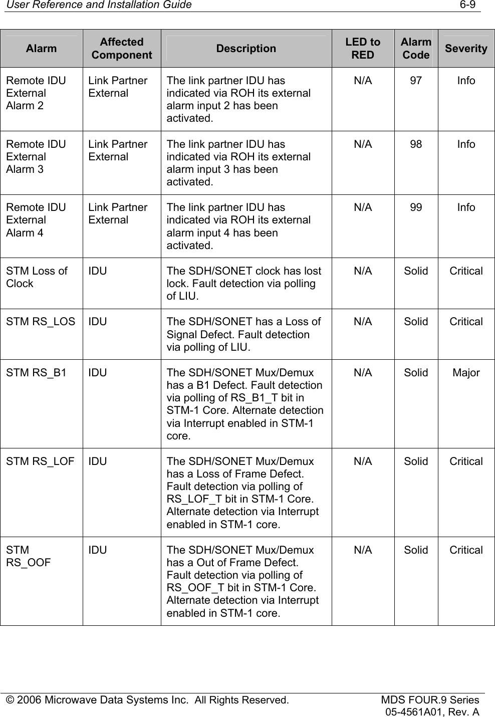
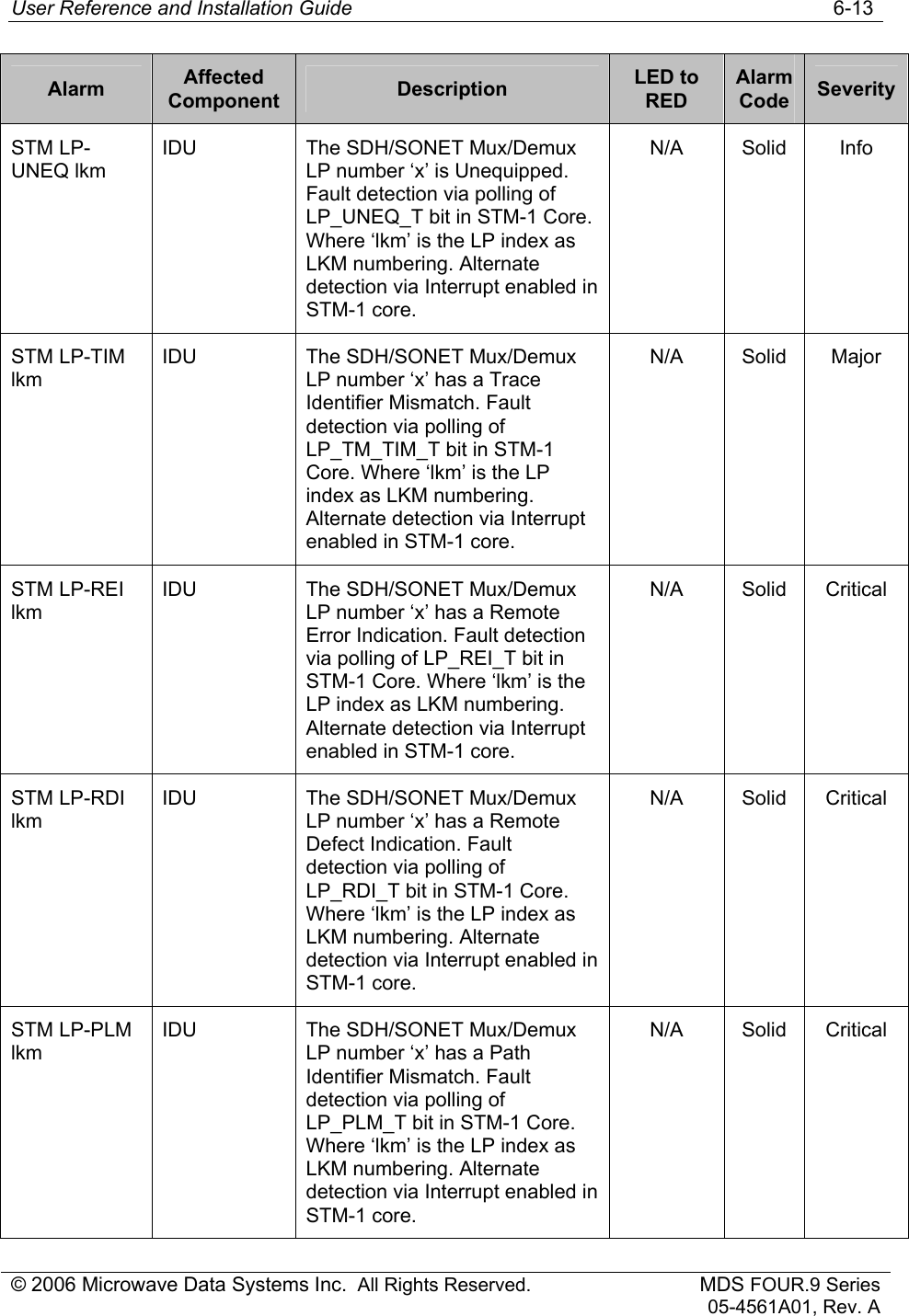
![User Reference and Installation Guide 3-10 © 2006 Microwave Data Systems Inc. All Rights Reserved. MDS FOUR.9 Series 05-4561A01, Rev. A MDS FIVE series Link Planner: 5.3GHz AvailabilityParameterOperating Frequency (MHz)Transmit Antenna Gain (dBi)Transmitter Output Power (dBmReceive Antenna Gain (dBi)Link Distance 3.93 milesFresnel Clearance Ratio1,2Climate FactorTerrain FactorMDS FIVE series Mode5.3GHz BandModem Data Rate (Mbps)Channel Bandwidth (MHz)Rece ive r Sensitivity3 (dBm)Link Fade Margin (dB)ODU RSSI (dBm)Availability (%)5.3G-25FE1 31.112E+6 30.0 -83 12 -71 99.99875.3G-25FE2 31.112E+6 20.0 -82 11 -71 99.99845.3G-25FE3 31.112E+6 13.3 -82 11 -71 99.99845.3G-50FE1 56.733E+6 30.0 -80 9 -71 99.99755.3G-50FE2 56.733E+6 20.0 -77 6 -71 99.99505.3G-50FE3 56.733E+6 13.3 -72 1 -71 99.98455.3G-100FE1 107.797E+6 30.0 -73 2 -71 99.98765.3G-16E1-2 36.918E+6 20.0 -82 11 -71 99.99845.3G-16T1-2 28.655E+6 20.0 -84 13 -71 99.99905.3G-16E1-3 36.918E+6 13.3 -82 11 -71 99.99845.3G-16T1-3 28.655E+6 13.3 -84 13 -71 99.9990Note1: FCC's definition; negative clearance indicates no optical LOS; range is [-1,…,0.6]; 0.6 is radio LOS condition.Note2: Accounting for single knife-edge diffraction loss only.Note3: BER<<1e-6.Note4: Listed data rates inlcudes 2 E1 Wayside channels, except f or 16E1/T1 modes.(miles)99.9% 99.99% 99.999%5.3G-25FE1 QPSK 3/4 -83 9535.3G-25FE2 16QAM 3/4 -82 9535.3G-25FE3 16QAM 3/4 -82 9535.3G-50FE1 16QAM 3/4 -80 8535.3G-50FE2 32QAM 4/5 -77 7425.3G-50FE3 64QAM 11/12 -72 5325.3G-100FE1 32QAM 9/10 -73 5325.3G-16E1-2 16QAM 3/4 -82 9535.3G-16T1-2 16QAM 3/4 -84 9635.3G-16E1-3 16QAM 7/8 -82 9535.3G-16T1-3 16QAM 7/8 -84 96323for Various AvailabilityMax DistanceValue5300236MDS FIVE series ModeModulation and Code RateRece ive r Sensitivity3 (dBm)0.600.251](https://usermanual.wiki/GE-MDS/DS-SERIES4/User-Guide-690488-Page-39.png)