GE MDS DS-SF9 Wireless Data Transceiver Module User Manual 05 6334A01 SF9 Integration Guide
GE MDS LLC Wireless Data Transceiver Module 05 6334A01 SF9 Integration Guide
UserManual.wiki
>
GE MDS
>
DS SF9 User Manual
Integration guide
Navigation menu
Upload a User Manual
Namespaces
Wiki Guide
HTML
PDF
Info
Views
User Manual
Discussion / Help
Navigation
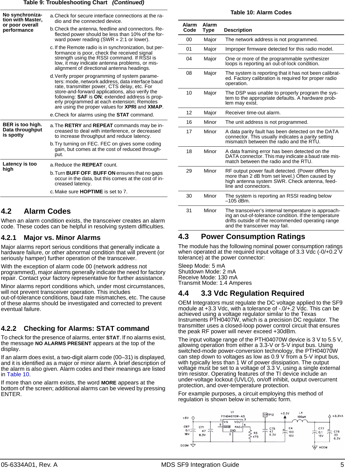
![2 MDS SF9 Integration Guide 05-6334A01, Rev. A6. Set the radio’s basic configuration with a PC terminal con-nected to J3. The three essential settings for all transceivers are:•Mode: Master, Remote, or Extension•Network Address: A unique number from 1 to 65000•Data Interface Parameters: bps, data bits, parity, stop bits7. Observe the transceiver LED status panel for proper indica-tions (see Table 2). Table 2: LED Indicator DescriptionsLED Name DescriptionRXD (CR3)Receive DataSerial receive data activity. Payload data from connected device.TXD (CR4)Transmit DataSerial transmit data activity. Payload data to connected device.DCD (CR5)Data Carrier DetectContinuous—Radio is receiving/sending syn-chronization framesOn within 10 seconds of power-up under nor-mal conditionsGP (CR6)General Purpose •Continuous—Power is applied to the radio; no problems detected• Flashing (5 times-per-second)—Fault indi-cation. See Troubleshooting•Off—Radio is unpowered or in Sleep mode8. In a normally operating system, you will see the following indi-cations within 16 seconds of start-up:•PWR lamp lit continuously•SYNC lamp lit continuously• Remote radio(s) transmitting data (TXD) and receiving data (RXD) with the Master station.9. Optimize the installation by checking:• Antenna aiming and SWR check• Data buffer setting (applicable to Modbus protocol)• Hoptime setting• Optimal baud rate setting• Radio interference checks3.0 RADIO PROGRAMMINGThere are no manual adjustments on the radio. All programming and control is performed through a PC connected to the radio’s J3 connector.3.1 User CommandsThe following tables provide descriptions of the various user commands for the transceiver. For additional detail refer to the TransNET OEM Integration Guide (05-3946A01). (This material is referenced as a resource for command details only. Other material in the guide pertains to a different TransNET model.)Table 3: Network Configuration—Master StationCOMMAND DESCRIPTIONAT [ON, OFF]BUFF [ON, OFF]FEC [ON, OFF]HOPTIME [7, 28]LPM [1, 0]REPEATRETRY [0–10]SAF [ON, OFF]SKIP [NONE, 1...8] NOTE: In the USA, a maximum of four zones may be skipped, per FCC rules. Check the regulatory requirements for your region before skipping zones.Table 4: Network-Wide DiagnosticsCOMMAND DESCRIPTIONDLINK [xxxxx/ON/OFF]DTYPE [NODE/ROOT]Enables Master station to emulate a modem and respond to AT commandsON = Seamless dataOFF = Fast byte throughput.Sets/disables FEC (Forward Error Correction) setting.Displays hop-time or sets it to 7 or 28 ms.Used at Master to set all associated stations in an energy-conservation mode.1 = Low-power mode enabled network-wide0 = Disable low-power mode (Default)Sets/displays the fixed downstream re-send count.Sets/displays the maximum upstream re-send count for ARQ (Automatic Repeat Request) operationEnables/disables the store-and-forward function for the network controlled by this Master unit.Skip one or more frequency zones—See note below regarding zone skips.Controls operation of diagnostic link function.Set radio’s operational characteristics for network-wide diagnosticsTable 5: Operational Configuration COMMAND DESCRIPTIONADDR [1–65000] Program network addressAMASK [0000 0000–FFFF FFFF] Alarm responseDefault: FFFF FFFFASENSE [HI/LO] Sense of the alarm output on Pin 6 of the DATA interface connector in the EIA-232 mode. Default: Alarm present = HIBAND [A, B, C] Selects one of three operating bands.(2.4 GHz Model Only)BAUD [xxxxx abc] Data communication parametersCODE [NONE, 1...255] Select the security/encryption setting in the radioCSADDR [1–65000] Used on a single Master/Remote net-work to support TDD-style simulated full-duplex.CTS [0–255] CTS delay in milliseconds(A value of 0 returns CTS immediately)CTSHOLD [0–60000] “Hold time” that CTS is present following last character from DATA port.DEVICE [DCE, CTS KEY] Device behavior: DCE (normal) or CTS KeyCOMMAND DESCRIPTION](https://usermanual.wiki/GE-MDS/DS-SF9/User-Guide-1434559-Page-2.png)
![05-6334A01, Rev. A MDS SF9 Integration Guide 3MODE [M, R, X] Operating mode: M = Master, R = Remote, X = ExtensionMRSSI [NONE, -40...-90] Minimum RSSI level required to preserve synchronization with a Master radio for Remotes in mobile service.OT [ON, OFF] Enables a 1-second delay on delivery of RXD serial data.OWN [xxxxx] Owner’s name, or alternate message(30 characters maximum)PORT [RS232, RS485] Data port (DATA connector) interface signaling mode: RS232 or RS485PWR [20–30] Power output in dBm RXD [0–255] Set RXD delay time for virtual seamless mode with low latencyRXTOT [NONE, 0–1440] Maximum duration (in minutes) before time-out alarm. Default is OFF.RTU [ON, OFF, 0–80] Enable or Disable unit’s built-in RTU simulator. Default is OFF. Set RTU address between zero and 80.SLEEP [ON, OFF] Enable or Disable the radio’s energy-conservation Sleep mode func-tion.UNIT [10000–60000] Unit address used for network-wide diagnostics. (Unique within associated network.)XADDR [0–31] This unit’s Extended addressTypically, the Master is set to zero (0).XMAP [00000000–FFFFFFFF] Included Extended units in MODE X. (Extensions and Remotes only) XPRI [0–31] Address of the primary Extended radio unit (Extension).XRSSI [NONE, -40...-120] Minimum RSSI level required to preserve synchronization with a non-primary radio. (Only meaningful when XPRI is not NONE)ZONE CLEAR Reset zone data statisticsTable 6: Operating Status—Display Only COMMAND DESCRIPTIONADDR Network addressAMASK Alarm mask (response)ASENSE Current sense of the alarm output.BAUD Data communication parameters. Exam-ple: BAUD 9600 8N1BUFF Data buffering mode: ON = seamless data, OFF = fast byte throughputCODE Security/encryption operational status.“NONE” (Inactive), or “ACTIVE”CTS CTS delay in milliseconds (0–255 ms)CTSHOLD “Hold time” that CTS is present following last character from DATA port.Table 5: Operational Configuration (Continued)COMMAND DESCRIPTIONDEVICE Device behavior Alternatives: DCE and CTS KEYHOPTIME Hop-time value in milliseconds (ms).LPMHOLD Time (0-1000 ms) provided to give an RTU time to respond before the radio goes to sleep.MODE Current operating mode: M = MasterR = RemoteX = Extension (Repeater)MRSSI Minimum RSSI level required to preserve synchronization with a Master radio for Remotes in mobile service.OWM Owner’s message or site nameOT Status (ON/OFF) of the 1-second delay on delivery of RXD serial data.OWN Owner’s name or system namePORT Current data port (DATA connector) inter-face signaling mode: RS232 or RS485PWR Forward power-output setting in dBmREPEAT The fixed downstream re-send count.RETRY The maximum upstream re-send count for ARQ (Automatic Repeat Request) operation.RSSI Received signal strength indicator (in dBm). Unavailable at Master unless SETUP is enabled.RTU RTU simulator’s operational status (ON/OFF)RXTOT The amount of time (in seconds) to wait before issuing a time-out alarm. SAF Store-and-forward mode status in this unit. (ON/OFF)SER Serial number of radioSHOW CON Display virtual modem connection statusSHOW PWR RF output power. Measured RF power in dBm.SHOW SYNC Information on synchronization sourceSKIP Frequency zones that are skippedSLEEP Radio’s Sleep Mode setting. (At Remotes Only)SREV Transceiver firmware revision levelSTAT Current alarm statusTEMP Transceiver’s internal temperature (°C)UNIT Programmed unit address for network-wide diagnosticsXADDR This unit’s Extended addressXPRI Address of the primary Extended radio unit (Extension).Table 6: Operating Status—Display Only (Continued)COMMAND DESCRIPTION](https://usermanual.wiki/GE-MDS/DS-SF9/User-Guide-1434559-Page-3.png)
![4 MDS SF9 Integration Guide 05-6334A01, Rev. ASuccessful troubleshooting is not difficult, but requires a logical approach. It is best to begin troubleshooting at the Master site, as the rest of the system depends on the Master for polling instructions and synchronization data. If the Master has problems, the operation of the entire network will be affected.Begin by checking the basics. All radios in the network must meet these requirements:• Adequate and stable primary power (3.3 Vdc) at J3.• An efficient and properly aligned antenna system• Secure connections (RF, data & power)• Proper programming of the radio’s operating parameters, especially Operating Mode (MODE), Network Address (ADDR), and interface Baud Rate (BAUD).• The correct interface between the radio and the connected data equipment (proper cable wiring, data format and timing).• In store-and-forward systems these additional areas should be checked or evaluated:• Look for duplicate XADDR values on MODE M and MODE X radios. Duplicates will cause failures (unless the radios are too far apart to hear each other).• Check for errors in the synchronization qualifiers, XPRI and XMAP, on corresponding Remote radios.• Verify SAF is enabled at the Master radio.4.1 LEDsTable 8 describes the functions of the LEDs on the transceiver board.Table 8: LED Indicator DescriptionsName DescriptionRXD Receive data activity on the J3 interface connectorTXD Transmit data activity on the J3 interface connectorSYNC Continuous—Radio is receiving/sending synchronization frames. Normally on within 10 seconds of power-up.PWR •Continuous—Power applied to radio; no faults•Flashing (5 times-per-second)—Fault indication. See Troubleshooting above, as well as chart below.•Off—Radio is unpowered or in Sleep modeTable 9 provides suggestions for resolving system difficulties that may be experienced in the radio system. If problems persist, contact the factory for further assistance.XMAP Included Extended units in MODE X. (Extensions and Remotes only). XRSSI Minimum RSSI level required to preserve synchronization with a non-primary radio. (Only meaningful when XPRI is not NONE)Table 7: Diagnostic and Test Functions COMMAND DESCRIPTIONKEY Enables the transmitter test. (must be in Setup mode).DKEY Turns off the transmitter test (must be in Setup mode).TX [xxxx] Set/display transmit test frequency (must be in Setup mode).RX [xxxx] Set/display receive test frequency. (must be in Setup mode).SETUP Enables Setup mode. Times out after 10 minutes. Press “Q” to quit.ZONE DATA Zone data statisticsZONE CLEAR Clears the Zone Data log4.0 TROUBLESHOOTINGTable 6: Operating Status—Display Only (Continued)COMMAND DESCRIPTIONTable 9: Troubleshooting Chart Difficulty Recommended System ChecksUnit isinoperative a.Check for the proper supply voltage (3.3 Vdc) at the power connector.b.The transceiver’s internal fuse may have opened.Interference is suspected a.Verify that the system has a unique network ad-dress. Nearby systems with the same address will cause interference.b.Check for interference by locking out affected zone(s) using the SKIP command.c.If omnidirectional antennas are used on Remote stations, consider changing to directional anten-nas. This will often limit interference to and from other stations.](https://usermanual.wiki/GE-MDS/DS-SF9/User-Guide-1434559-Page-4.png)