GE MDS DS-SF9 Wireless Data Transceiver Module User Manual 05 6334A01 SF9 Integration Guide
GE MDS LLC Wireless Data Transceiver Module 05 6334A01 SF9 Integration Guide
GE MDS >
Integration guide
1.0 INTRODUCTION
05-6334A01, Rev. A MDS SF9 Integration Guide 1
MDS TransNET-SF9
Publication No. 05-6334A01, Rev. 01
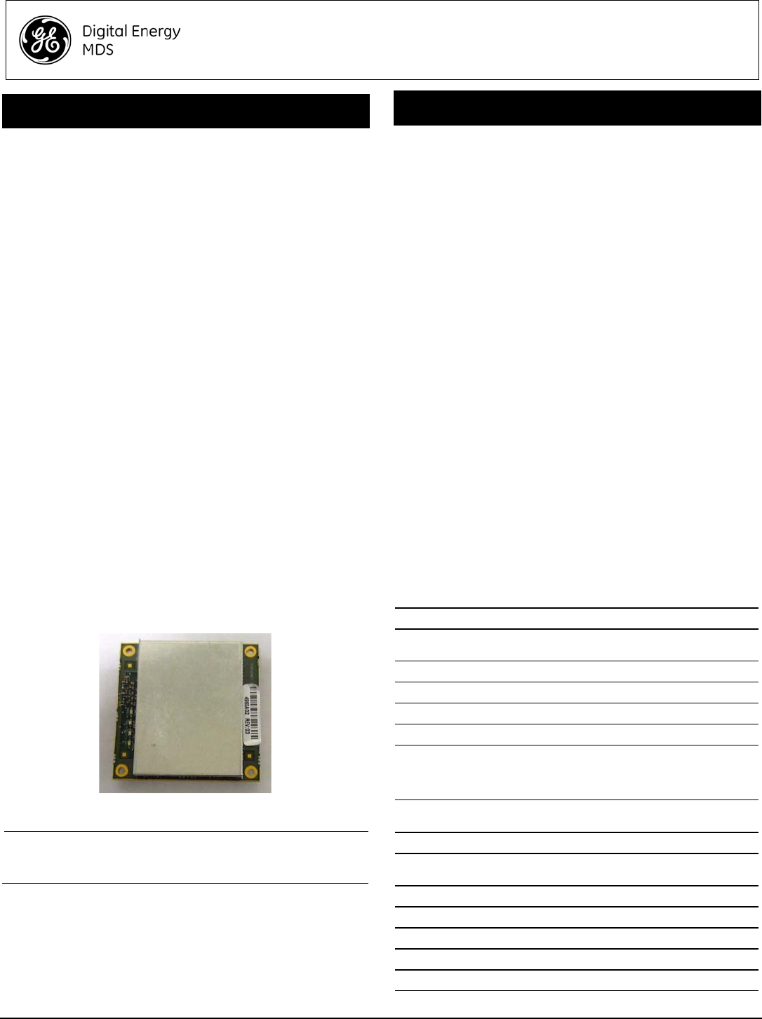
The MDS TransNET-SF9 (Figure 1), is a modular spread spectrum
transceiver designed for use in the license-free 902-928 MHz
band. The unit is designed for use inside data equipment to provide
reliable connectivity in wireless networks.
The SF9 employs a closed-loop power control circuit, ensuring that
the RF output never exceeds +30 dBm at the antenna connector.
The module is designed for OEM use only. Host systems, if used
with antennas having standard connectors, must be professionally
installed. Host systems using integrated antennas or unique
antenna connectors must be factory configured by the OEM to
operate at the correct output power setting. Refer to the table at the
end of this guide to determine applicable antenna types and the RF
output power allowed.
Electronic copies of this document and other GE MDS user guides
are available free of charge at www.gemds.com.
1.1 Transceiver Features
The SF-9 maximizes performance and flexibility in wireless
networks, offering the following key features:
• 128 frequencies over 902–928 MHz, divided into 8 zones
• User-selectable option to skip sub-bands with interference
• 65,000 available network addresses
• Network-wide configuration from the Master station, elimi-
nating most trips to Remote sites
• Data transparency ensures compatibility with virtually all
asynchronous SCADA system terminals.
• Peak-hold RSSI averaged over eight hop cycles
• Operation at up to 115,200 bps continuous data flow
• Store-and-Forward repeater operation
• Data latency typically less than 10 ms
• Same hardware for Master or Remote configuration
• Supports RS/EIA-232 and RS/EIA-485 user interface
• Low current draw; typically less than 8 mA in sleep mode
• Operates at 3.3 Vdc at the power connector
Figure 1. SF9 Transceiver Module
(J3 Data/Power and J200 Antenna Connectors on other side)
NOTE: Some features may not be available on all units, based on
the options purchased, or regulatory constraints in the
country of operation.
1.2 Accessories
GE MDS offers an Accessories Selection Guide listing additional
items that may be used with our products. Contact your factory
representative or visit www.gemds.com for the latest copy.
2.0 INSTALLATION
The transceiver is designed for installation in existing electronic
equipment. It mounts to any flat surface using screws through the
four holes provided in the corners of the PC board.
Only two cable connections required to the radio; J3, the
Power/Data connector, and J200, the Antenna connector. It is
recommended that the module be installed in a manner that
permits viewing the four status LEDs (CR3, 4, 5, and 6) during
operation. These LEDs provide important information that is useful
during startup and optimization of the radio link.
Antennas used with the radio can be either a Yagi directional type
(often used at remote sites) or an omni-directional type used for
short range applications or at Master stations. Contact your sales
representative for information on available antennas.
Follow these steps to install the transceiver module:
1. Select a suitable mounting location for the module. This
should be a flat surface close enough to the power/data and
antenna cabling so that these will reach their respective
connectors.
2. Secure the module to the surface using suitable screws
through the mounting holes in each corner of the radio’s PC
board. Use spacers as necessary to achieve required height.
(Mounting hardware is not supplied.)
3. Select and install an appropriate antenna and feedline for your
system coverage requirements.
4. Connect the antenna coaxial lead to J200 on the module. It
accepts a Type-UMC female coaxial connector.
5. Prepare the power/data cabling for connection to J3 on the
module. It accepts a Molex SlimStackTM 20 pin receptacle.
Use only the required data pins for the application (see
Table 1 for pin information). The input power applied to J3
must be 3.3 Vdc (-0/+0.2 V). Connect the plug to J3.
Table 1: J3 Power/Data Connector Pinouts
Pin(s) Description
1, 2, 7, 8 Signal Ground—Connects to ground (negative supply
potential) on the radio’s PC board and chassis
3, 4, 5, 6 3.3 Vdc Input
9Alarm
10 DCD_LED
11 Serial Configuration
12 CTS (Clear-to-Send)—Goes “high” after the
programmed CTS delay time has elapsed (DCE), or keys
an attached radio when RF data arrives (CTS KEY).
CTS_N-485_DE
13 RXD (Received Data)—Supplies received data to the
connected device
14 RTS (Request-to-Send)
15 TXD (Transmitted Data)—
Accepts TX data from the connected device
16 Power Supply Shutdown PS_SHDN
17 Sleep
18 DIAG_RXD
19 DIAG_TXD
20 Reserved. Do not connect.

2 MDS SF9 Integration Guide 05-6334A01, Rev. A
6. Set the radio’s basic configuration with a PC terminal con-
nected to J3. The three essential settings for all transceivers
are:
•Mode: Master, Remote, or Extension
•Network Address: A unique number from 1 to 65000
•Data Interface Parameters: bps, data bits, parity, stop
bits
7. Observe the transceiver LED status panel for proper indica-
tions (see Table 2).
Table 2: LED Indicator Descriptions
LED Name Description
RXD (CR3)
Receive Data
Serial receive data activity. Payload data from
connected device.
TXD (CR4)
Transmit Data
Serial transmit data activity. Payload data to
connected device.
DCD (CR5)
Data Carrier Detect
Continuous—Radio is receiving/sending syn-
chronization frames
On within 10 seconds of power-up under nor-
mal conditions
GP (CR6)
General Purpose •Continuous—Power is applied to the radio;
no problems detected
• Flashing (5 times-per-second)—Fault indi-
cation. See Troubleshooting
•Off—Radio is unpowered or in Sleep mode
8. In a normally operating system, you will see the following indi-
cations within 16 seconds of start-up:
•PWR lamp lit continuously
•SYNC lamp lit continuously
• Remote radio(s) transmitting data (TXD) and receiving data
(RXD) with the Master station.
9. Optimize the installation by checking:
• Antenna aiming and SWR check
• Data buffer setting (applicable to Modbus protocol)
• Hoptime setting
• Optimal baud rate setting
• Radio interference checks
3.0 RADIO PROGRAMMING
There are no manual adjustments on the radio. All programming
and control is performed through a PC connected to the radio’s J3
connector.
3.1 User Commands
The following tables provide descriptions of the various user
commands for the transceiver. For additional detail refer to the
TransNET OEM Integration Guide (05-3946A01). (This material is
referenced as a resource for command details only. Other material
in the guide pertains to a different TransNET model.)
Table 3: Network Configuration—Master Station
COMMAND DESCRIPTION
AT [ON, OFF]
BUFF [ON, OFF]
FEC [ON, OFF]
HOPTIME [7, 28]
LPM [1, 0]
REPEAT
RETRY [0–10]
SAF [ON, OFF]
SKIP [NONE, 1...8]
NOTE: In the USA, a maximum of four zones may be skipped,
per FCC rules. Check the regulatory requirements for
your region before skipping zones.
Table 4: Network-Wide Diagnostics
COMMAND DESCRIPTION
DLINK [xxxxx/ON/OFF]
DTYPE [NODE/ROOT]
Enables Master station to emulate a
modem and respond to AT commands
ON = Seamless data
OFF = Fast byte throughput.
Sets/disables FEC
(Forward Error Correction) setting.
Displays hop-time or sets it to 7 or
28 ms.
Used at Master to set all associated
stations in an energy-conservation
mode.
1 = Low-power mode enabled
network-wide
0 = Disable low-power mode (Default)
Sets/displays the fixed downstream
re-send count.
Sets/displays the maximum upstream
re-send count for ARQ (Automatic
Repeat Request) operation
Enables/disables the
store-and-forward function for the
network controlled by this Master unit.
Skip one or more frequency zones—
See note below regarding zone skips.
Controls operation of diagnostic link
function.
Set radio’s operational characteristics
for network-wide diagnostics
Table 5: Operational Configuration
COMMAND DESCRIPTION
ADDR [1–65000] Program network address
AMASK [0000
0000–FFFF FFFF] Alarm response
Default: FFFF FFFF
ASENSE [HI/LO] Sense of the alarm output on Pin 6 of the
DATA interface connector in the EIA-232
mode. Default: Alarm present = HI
BAND [A, B, C] Selects one of three operating bands.
(2.4 GHz Model Only)
BAUD [xxxxx abc] Data communication parameters
CODE [NONE, 1...255] Select the security/encryption setting in
the radio
CSADDR [1–65000] Used on a single Master/Remote net-
work to support TDD-style simulated
full-duplex.
CTS [0–255] CTS delay in milliseconds
(A value of 0 returns CTS immediately)
CTSHOLD [0–60000] “Hold time” that CTS is present following
last character from DATA port.
DEVICE [DCE, CTS
KEY] Device behavior:
DCE (normal) or CTS Key
COMMAND DESCRIPTION

05-6334A01, Rev. A MDS SF9 Integration Guide 3
MODE [M, R, X] Operating mode:
M = Master, R = Remote, X = Extension
MRSSI [NONE,
-40...-90] Minimum RSSI level required to preserve
synchronization with a Master radio for
Remotes in mobile service.
OT [ON, OFF] Enables a 1-second delay on delivery of
RXD serial data.
OWN [xxxxx] Owner’s name, or alternate message
(30 characters maximum)
PORT [RS232, RS485] Data port (DATA connector) interface
signaling mode: RS232 or RS485
PWR [20–30] Power output in dBm
RXD [0–255] Set RXD delay time for virtual seamless
mode with low latency
RXTOT [NONE, 0–1440] Maximum duration (in minutes) before
time-out alarm. Default is OFF.
RTU [ON, OFF, 0–80] Enable or Disable unit’s built-in RTU
simulator. Default is OFF. Set RTU
address between zero and 80.
SLEEP [ON, OFF] Enable or Disable the radio’s
energy-conservation Sleep mode func-
tion.
UNIT [10000–60000] Unit address used for network-wide
diagnostics. (Unique within associated
network.)
XADDR [0–31] This unit’s Extended address
Typically, the Master is set to zero (0).
XMAP
[00000000–FFFFFFFF] Included Extended units in MODE X.
(Extensions and Remotes only)
XPRI [0–31] Address of the primary Extended radio
unit (Extension).
XRSSI [NONE,
-40...-120] Minimum RSSI level required to preserve
synchronization with a non-primary radio.
(Only meaningful when XPRI is not
NONE)
ZONE CLEAR Reset zone data statistics
Table 6: Operating Status—Display Only
COMMAND DESCRIPTION
ADDR Network address
AMASK Alarm mask (response)
ASENSE Current sense of the alarm output.
BAUD Data communication parameters. Exam-
ple: BAUD 9600 8N1
BUFF Data buffering mode: ON = seamless
data, OFF = fast byte throughput
CODE Security/encryption operational status.
“NONE” (Inactive), or “ACTIVE”
CTS CTS delay in milliseconds (0–255 ms)
CTSHOLD “Hold time” that CTS is present following
last character from DATA port.
Table 5: Operational Configuration (Continued)
COMMAND DESCRIPTION
DEVICE Device behavior
Alternatives: DCE and CTS KEY
HOPTIME Hop-time value in milliseconds (ms).
LPMHOLD Time (0-1000 ms) provided to give an
RTU time to respond before the radio
goes to sleep.
MODE Current operating mode:
M = Master
R = Remote
X = Extension (Repeater)
MRSSI Minimum RSSI level required to preserve
synchronization with a Master radio for
Remotes in mobile service.
OWM Owner’s message or site name
OT Status (ON/OFF) of the 1-second delay
on delivery of RXD serial data.
OWN Owner’s name or system name
PORT Current data port (DATA connector) inter-
face signaling mode: RS232 or RS485
PWR Forward power-output setting in dBm
REPEAT The fixed downstream re-send count.
RETRY The maximum upstream re-send count
for ARQ (Automatic Repeat Request)
operation.
RSSI Received signal strength indicator (in
dBm). Unavailable at Master unless
SETUP is enabled.
RTU RTU simulator’s operational status
(ON/OFF)
RXTOT The amount of time (in seconds) to wait
before issuing a time-out alarm.
SAF Store-and-forward mode status in this
unit. (ON/OFF)
SER Serial number of radio
SHOW CON Display virtual modem connection status
SHOW PWR RF output power.
Measured RF power in dBm.
SHOW SYNC Information on synchronization source
SKIP Frequency zones that are skipped
SLEEP Radio’s Sleep Mode setting.
(At Remotes Only)
SREV Transceiver firmware revision level
STAT Current alarm status
TEMP Transceiver’s internal temperature (°C)
UNIT Programmed unit address for
network-wide diagnostics
XADDR This unit’s Extended address
XPRI Address of the primary Extended radio
unit (Extension).
Table 6: Operating Status—Display Only (Continued)
COMMAND DESCRIPTION

4 MDS SF9 Integration Guide 05-6334A01, Rev. A
Successful troubleshooting is not difficult, but requires a logical
approach. It is best to begin troubleshooting at the Master site, as
the rest of the system depends on the Master for polling
instructions and synchronization data. If the Master has problems,
the operation of the entire network will be affected.
Begin by checking the basics. All radios in the network must meet
these requirements:
• Adequate and stable primary power (3.3 Vdc) at J3.
• An efficient and properly aligned antenna system
• Secure connections (RF, data & power)
• Proper programming of the radio’s operating parameters,
especially Operating Mode (MODE), Network Address
(ADDR), and interface Baud Rate (BAUD).
• The correct interface between the radio and the connected
data equipment (proper cable wiring, data format and timing).
• In store-and-forward systems these additional areas should be
checked or evaluated:
• Look for duplicate XADDR values on MODE M and
MODE X radios. Duplicates will cause failures (unless the
radios are too far apart to hear each other).
• Check for errors in the synchronization qualifiers, XPRI
and XMAP, on corresponding Remote radios.
• Verify SAF is enabled at the Master radio.
4.1 LEDs
Table 8 describes the functions of the LEDs on the transceiver
board.
Table 8: LED Indicator Descriptions
Name Description
RXD Receive data activity on the J3 interface connector
TXD Transmit data activity on the J3 interface connector
SYNC Continuous—Radio is receiving/sending synchronization
frames. Normally on within 10 seconds of power-up.
PWR •Continuous—Power applied to radio; no faults
•Flashing (5 times-per-second)—Fault indication. See
Troubleshooting above, as well as chart below.
•Off—Radio is unpowered or in Sleep mode
Table 9 provides suggestions for resolving system difficulties that
may be experienced in the radio system. If problems persist,
contact the factory for further assistance.
XMAP Included Extended units in MODE X.
(Extensions and Remotes only).
XRSSI Minimum RSSI level required to preserve
synchronization with a non-primary radio.
(Only meaningful when XPRI is not
NONE)
Table 7: Diagnostic and Test Functions
COMMAND DESCRIPTION
KEY Enables the transmitter test.
(must be in Setup mode).
DKEY Turns off the transmitter test
(must be in Setup mode).
TX [xxxx] Set/display transmit test frequency
(must be in Setup mode).
RX [xxxx] Set/display receive test frequency.
(must be in Setup mode).
SETUP Enables Setup mode.
Times out after 10 minutes. Press “Q” to
quit.
ZONE DATA Zone data statistics
ZONE CLEAR Clears the Zone Data log
4.0 TROUBLESHOOTING
Table 6: Operating Status—Display Only (Continued)
COMMAND DESCRIPTION
Table 9: Troubleshooting Chart
Difficulty Recommended System Checks
Unit is
inoperative a.Check for the proper supply voltage (3.3 Vdc) at
the power connector.
b.The transceiver’s internal fuse may have opened.
Interference is
suspected a.Verify that the system has a unique network ad-
dress. Nearby systems with the same address
will cause interference.
b.Check for interference by locking out affected
zone(s) using the SKIP command.
c.If omnidirectional antennas are used on Remote
stations, consider changing to directional anten-
nas. This will often limit interference to and from
other stations.

05-6334A01, Rev. A MDS SF9 Integration Guide 5
4.2 Alarm Codes
When an alarm condition exists, the transceiver creates an alarm
code. These codes can be helpful in resolving system difficulties.
4.2.1 Major vs. Minor Alarms
Major alarms report serious conditions that generally indicate a
hardware failure, or other abnormal condition that will prevent (or
seriously hamper) further operation of the transceiver.
With the exception of alarm code 00 (network address not
programmed), major alarms generally indicate the need for factory
repair. Contact your factory representative for further assistance.
Minor alarms report conditions which, under most circumstances,
will not prevent transceiver operation. This includes
out-of-tolerance conditions, baud rate mismatches, etc. The cause
of these alarms should be investigated and corrected to prevent
eventual failure.
4.2.2 Checking for Alarms: STAT command
To check for the presence of alarms, enter STAT. If no alarms exist,
the message NO ALARMS PRESENT appears at the top of the
display.
If an alarm does exist, a two-digit alarm code (00–31) is displayed,
and it is identified as a major or minor alarm. A brief description of
the alarm is also given. Alarm codes and their meanings are listed
in Table 10.
If more than one alarm exists, the word MORE appears at the
bottom of the screen; additional alarms can be viewed by pressing
ENTER.
Table 10: Alarm Codes
Alarm
Code Alarm
Type
Description
00 Major The network address is not programmed.
01 Major Improper firmware detected for this radio model.
04 Major One or more of the programmable synthesizer
loops is reporting an out-of-lock condition.
08 Major The system is reporting that it has not been calibrat-
ed. Factory calibration is required for proper radio
operation.
10 Major The DSP was unable to properly program the sys-
tem to the appropriate defaults. A hardware prob-
lem may exist.
12 Major Receiver time-out alarm.
16 Minor The unit address is not programmed.
17 Minor A data parity fault has been detected on the DATA
connector. This usually indicates a parity setting
mismatch between the radio and the RTU.
18 Minor A data framing error has been detected on the
DATA connector. This may indicate a baud rate mis-
match between the radio and the RTU.
29 Minor RF output power fault detected. (Power differs by
more than 2 dB from set level.) Often caused by
high antenna system SWR. Check antenna, feed-
line and connectors.
30 Minor The system is reporting an RSSI reading below
–105 dBm.
31 Minor The transceiver’s internal temperature is approach-
ing an out-of-tolerance condition. If the temperature
drifts outside of the recommended operating range
and the transceiver may fail.
4.3 Power Consumption Ratings
The module has the following nominal power consumption ratings
when operated at the required input voltage of 3.3 Vdc (-0/+0.2 V
tolerance) at the power connector:
Sleep Mode: 5 mA
Shutdown Mode: 2 mA
Receive Mode: 130 mA
Transmit Mode: 1.4 Amperes
4.4 3.3 Vdc Regulation Required
OEM Integrators must regulate the DC voltage applied to the SF9
module at +3.3 Vdc, with a tolerance of -.0/+.2 Vdc. This can be
achieved using a voltage regulator similar to the Texas
Instruments PTH0407W, which is a precision DC regulator. The
transmitter uses a closed-loop power control circuit that ensures
the peak RF power will never exceed +30dBm.
The input voltage range of the PTH04070W device is 3 V to 5.5 V,
allowing operation from either a 3.3-V or 5-V input bus. Using
switched-mode power-conversion technology, the PTH04070W
can step down to voltages as low as 0.9 V from a 5-V input bus,
with typically less than 1 W of power dissipation. The output
voltage must be set to a voltage of 3.3 V, using a single external
trim resistor. Operating features of the TI device include an
under-voltage lockout (UVLO), on/off inhibit, output overcurrent
protection, and over-temperature protection.
For example purposes, a circuit employing this method of
regulation is shown below in schematic form.
No synchroniza-
tion with Master,
or poor overall
performance
a.Check for secure interface connections at the ra-
dio and the connected device.
b.Check the antenna, feedline and connectors. Re-
flected power should be less than 10% of the for-
ward power reading (SWR » 2:1 or lower).
c.If the Remote radio is in synchronization, but per-
formance is poor, check the received signal
strength using the RSSI command. If RSSI is
low, it may indicate antenna problems, or mis-
alignment of directional antenna headings.
d.Verify proper programming of system parame-
ters: mode, network address, data interface baud
rate, transmitter power, CTS delay, etc. For
store-and-forward applications, also verify the
following: SAF is ON; extended address is prop-
erly programmed at each extension; Remotes
are using the proper values for XPRI and XMAP.
e.Check for alarms using the STAT command.
BER is too high.
Data throughput
is spotty
a.The RETRY and REPEAT commands may be in-
creased to deal with interference, or decreased
to increase throughput and reduce latency.
b.Try turning on FEC. FEC on gives some coding
gain, but comes at the cost of reduced through-
put.
Latency is too
high a.Reduce the REPEAT count.
b.Turn BUFF OFF. BUFF ON ensures that no gaps
occur in the data, but this comes at the cost of in-
creased latency.
c.Make sure HOPTIME is set to 7.
Table 9: Troubleshooting Chart (Continued)

6 MDS SF9 Integration Guide 05-6334A01, Rev. A
4.5 Technical Assistance
Factory technical assistance is available by contacting GE MDS
during business hours (8:30 AM to 6:00 PM Eastern Time). Use
one of the following means to contact the factory:
Telephone: (585) 241-5510 FAX: (585) 242-8369
E-mail: gemds.techsupport@ge.com
Web: www.gemds.com
FCC Part 15 and Industry Canada RSS Notice
This device complies with Part 15 of the FCC Rules and Industry
Canada license-exempt RSS standard(s). Operation is subject to
the following two conditions: (1) this device may not cause
interference, and (2) this device must accept any interference that
may cause undesired operation of the device.
a) Under Industry Canada regulations, this radio transmitter may
only operate using an antenna of a type and maximum (or lesser)
gain approved for the transmitter by Industry Canada. To reduce
potential radio interference to other users, the antenna type and its
gain should be so chosen that the equivalent isotropically radiated
power (e.i.r.p.) is not more than that necessary for successful
communication.
b) The radio transmitter described herein (IC ID: 101D-SF9) has
been approved by Industry Canada to operate with the antenna
types listed below with the maximum permissible gain and required
antenna impedance for each antenna type indicated. Antenna
types not included in this list, having a gain greater than the
maximum gain indicated for that type, are strictly prohibited for use
with this device.
Warning: Changes or modifications not expressly approved by the
manufacturer could void the user’s authority to operate the
equipment.
Cet appareil est conforme à la Partie 15 des règlements de la FCC
et Industrie Canada exempts de licence standard RSS (s). Son
utilisation est soumise à deux conditions: (1) ce dispositif ne peut
causer des interférences, (2) cet appareil doit accepter toute
interférence pouvant causer un mauvais fonctionnement du
dispositif.
a) En vertu des règlements d'Industrie Canada, cet émetteur radio
ne peut fonctionner avec une antenne d'un type et un maximum
(ou moins) approuvés pour gagner de l'émetteur par Industrie
Canada. Pour réduire le risque d'interférence aux autres
utilisateurs, le type d'antenne et son gain doivent être choisies de
façon que la puissance isotrope rayonnée équivalente (PIRE) ne
dépasse pas ce qui est nécessaire pour une communication
réussie.
b) L'émetteur radio décrit ci-après (IC ID: 101D-SF9) a été
approuvé par Industrie Canada pour fonctionner avec les types
d'antennes énumérées ci-dessous avec le gain maximal
admissible et nécessaire antenne d'impédance pour chaque type
d'antenne indiqué. Types d'antennes ne figurent pas dans cette
liste, ayant un gain supérieur au gain maximum indiqué pour ce
type, sont strictement interdites pour une utilisation avec cet
appareil.
Antenna System Gain
(Antenna Gain in dBi1
1. Most antenna manufacturers rate antenna gain
in dBd. To convert to dBi, add 2.15 dB.
minus Feedline Loss in dB2)
6 (or less) 30 36
828 36
10 26 36
12 24 36
14 22 36
16 20 36
FCC Limited Modular Approval Notice
This device is offered as an FCC Part 15 Unlicensed Limited
Modular Transmitter (LMA). The transmitter module is approved
for use only with specific antenna, cable and output power
configurations that have been tested and approved for use when
installed in devices approved by third-party OEMs, or produced by
the Grantee (GE MDS). Modifications to the radio, the antenna
system, or power output, that have not been explicitly specified by
the manufacturer are not permitted, and may render the radio
non-compliant with applicable regulatory authorities.
When this device is placed inside an enclosure, a durable label
must be affixed to the outside of the enclosure indicating the unit’s
FCC ID Number.
The antenna(s) to be used with this module must be installed with
consideration to the guidelines for RF exposure risk to all nearby
personnel, and must not be co-located or operating in conjunction
with any other antenna or transmitter.
RF Exposure Notices
Professional installation required. The radio equipment described
in this guide emits radio frequency energy. Although the power
level is low, the concentrated energy from a directional antenna
may pose a health hazard. Do not allow people to come closer than
23 cm (9 inches) to the antenna when the transmitter is operating
in indoor or outdoor environments.
In mobile applications (vehicle mounted) the above separation
distance must be maintained at all times. More information on RF
exposure is available online at:
www.fcc.gov/oet/info/documents/bulletins
L'énergie concentrée en provenance d'une antenne directionnelle
peut présenter un danger pour la santé. Ne pas permettre aux
gens de s'approcher à moins de 23 cm à l'avant de l'antenne
lorsque l'émetteur est en opération. On doit augmenter la distance
proportionnellement si on utilise des antennes ayant un gain plus
élevé . Ce guide est destiné à être utilisé par un installateur
professionnel. Plus d'informations sur l'exposition aux rayons RF
peut être consulté en ligne à l'adresse suivante:
www.fcc.gov/oet/info/documents/bulletins
2. Feedline loss varies by cable type and length.
Consult manufacturer data.
Maximum Power
Setting
(in dBm) EIRP
(in dBm)