GE MDS DS-TD220MAX Narrowband Data Transceiver User Manual GE MDS TD220 Manual
GE MDS LLC Narrowband Data Transceiver GE MDS TD220 Manual
UserManual.wiki
>
GE MDS
>
DS TD220MAX User Manual
Users Manual
Navigation menu
Upload a User Manual
Namespaces
Wiki Guide
HTML
PDF
Info
Views
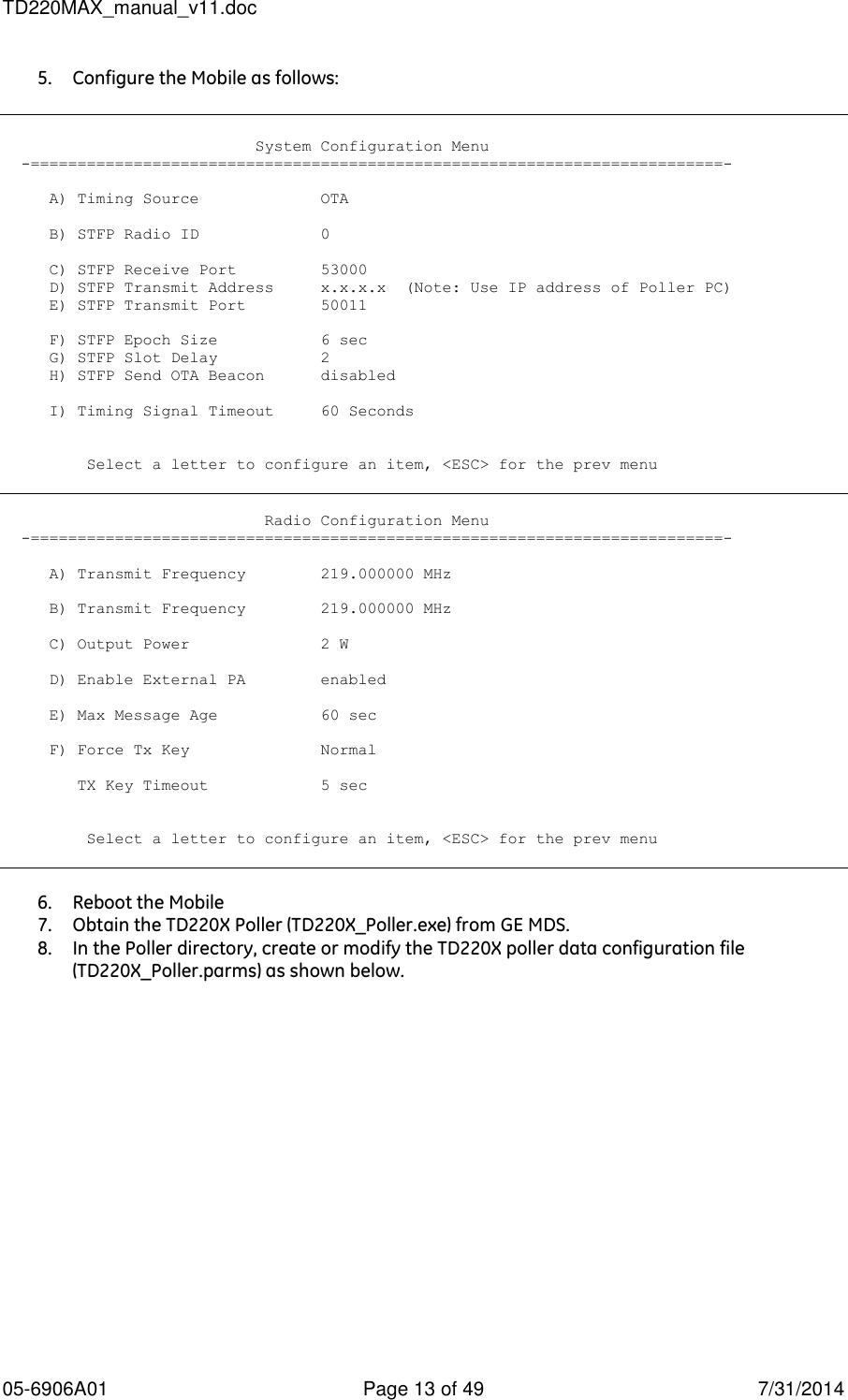
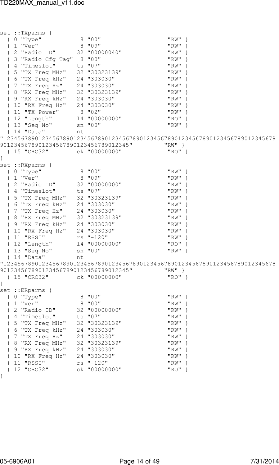
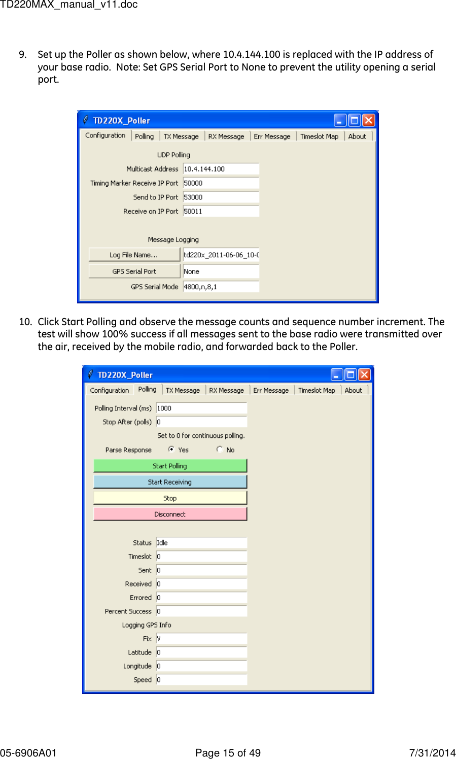
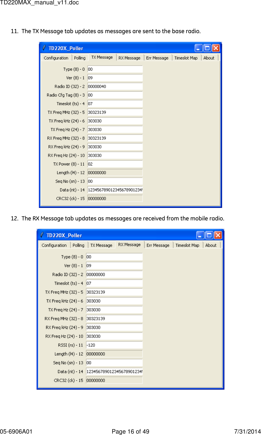
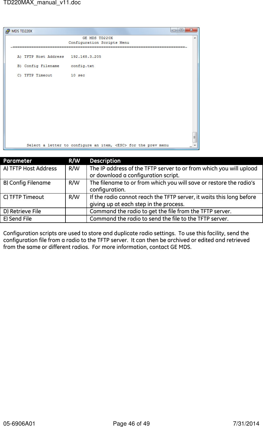
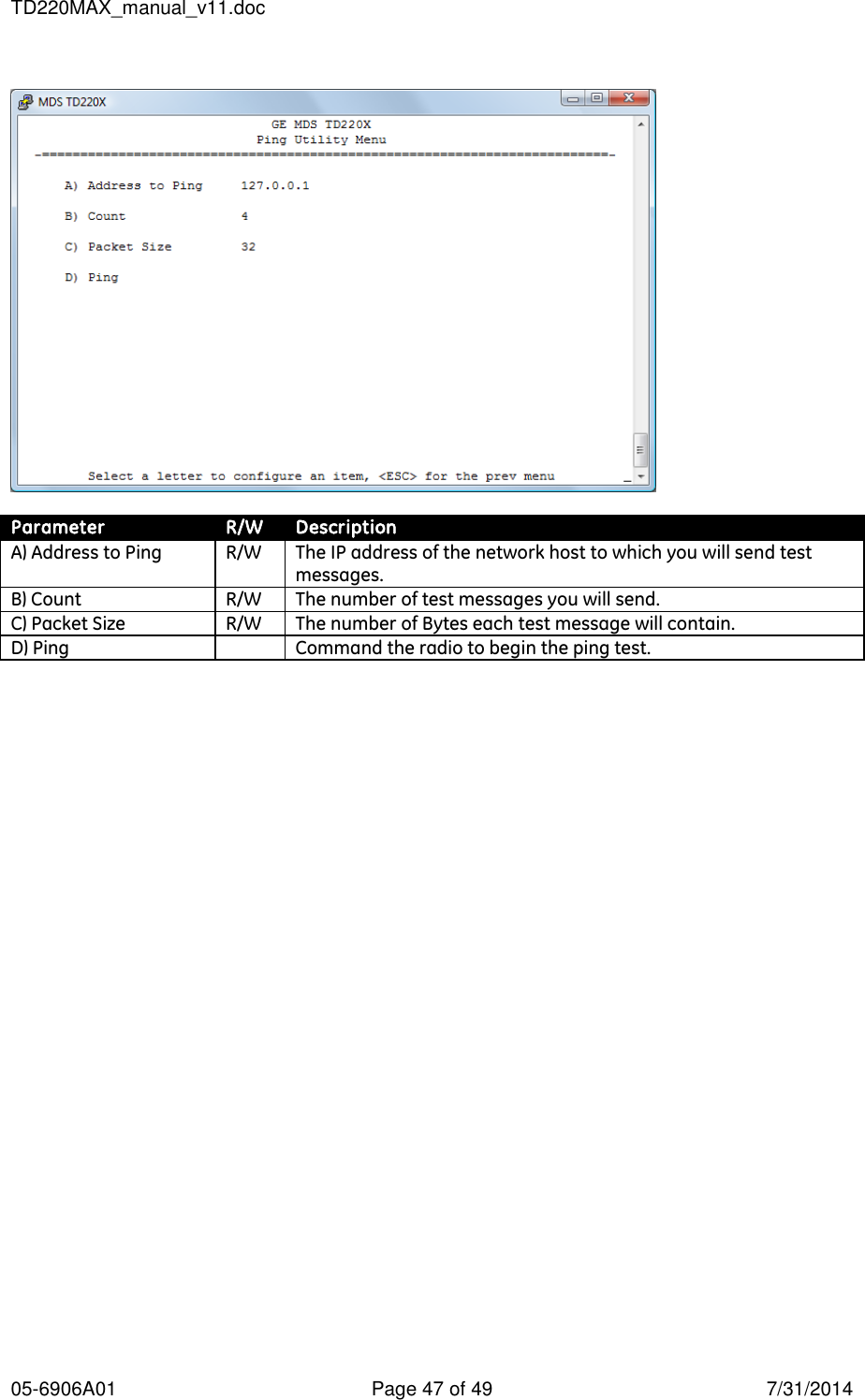
User Manual
Discussion / Help
Navigation