GE MDS DS-TD220MAX Narrowband Data Transceiver User Manual GE MDS TD220 Manual
GE MDS LLC Narrowband Data Transceiver GE MDS TD220 Manual
GE MDS >
Users Manual
TD220MAX_manual_v11.doc
05-6906A01 Page 1 of 49 7/31/2014
GE MDS TD220MAX Manual
P/N 05-6906A01
Version 11
TD220MAX_manual_v11.doc
05-6906A01 Page 2 of 49 7/31/2014
Table of Contents
1 Important Information ............................................................................................................ 3
1.1 Antenna Installation Warnings ........................................................................................ 3
1.2 ESD Notice ..................................................................................................................... 3
1.3 FCC Approval Notice ...................................................................................................... 3
1.4 FCC Part 15 Notice ........................................................................................................ 3
1.5 FCC Part 80 Notice ........................................................................................................ 4
1.6 Industry Canada ICES-003 and RSS-119 (Pending) ..................................................... 4
2 Introduction ........................................................................................................................... 5
3 Interfaces .............................................................................................................................. 6
3.1 Data Interface (DB-25) ................................................................................................... 6
3.2 USB ................................................................................................................................ 7
3.3 Power .............................................................................................................................. 7
3.4 Antenna Connector ......................................................................................................... 7
4 Common Setup Tasks ........................................................................................................... 8
4.1 Key the Transmitter for Test Purposes ........................................................................... 8
4.2 Prepare the Network Interface for a Radio ..................................................................... 8
4.3 Upgrade the Firmware .................................................................................................... 8
4.3.1 Introduction .............................................................................................................. 8
4.3.2 Installing TD220X Firmware by TFTP ...................................................................... 9
4.3.3 Upload Procedure .................................................................................................... 9
4.4 Set Up a GPS Base Unit ................................................................................................ 9
4.5 Set Up a PTP Base Unit ................................................................................................. 10
4.6 Set Up an OTA Mobile Unit ............................................................................................ 10
4.7 Perform Test Polling ....................................................................................................... 11
4.8 Perform Field Survey ...................................................................................................... 18
4.8.1 Set up the Base System .......................................................................................... 18
4.8.2 Set up the Mobile System ........................................................................................ 21
5 Menu Interface ...................................................................................................................... 24
5.1 Main Menu ...................................................................................................................... 26
5.2 Network Configuration Menus ........................................................................................ 27
5.3 System Configuration Menu ........................................................................................... 31
5.4 Radio Configuration Menu .............................................................................................. 32
5.5 GPS Configuration Menu ................................................................................................ 34
5.6 PTP Configuration Menu ................................................................................................ 35
5.7 Security Configuration Menu .......................................................................................... 36
5.8 Statistics/Logging Menus ................................................................................................ 37
5.9 Device Information Menus .............................................................................................. 42
5.10 Maintenance/Tools Menus ............................................................................................. 44
6 Troubleshooting .................................................................................................................... 48
7 Change Log ........................................................................................................................... 49

TD220MAX_manual_v11.doc
05-6906A01 Page 3 of 49 7/31/2014
1 Important Information
1.1 Antenna Installation Warnings
1. All antenna installation and servicing is to be performed by qualified technical personnel
only. When servicing the antenna, or working at distances closer than those listed below,
ensure the transmitter has been disabled.
2. Depending upon the application and the gain of the antenna, the total composite power
could exceed 90 watts EIRP. For fixed/mobile configuration, the distances in the table below
must be followed.
Antenna Gain vs. Minimum Safety Distance
(Based upon a 50% Duty Cycle, 0 dB Feedline Loss) Uncontrolled Environment Exposure limits
Fixed/Mobile Antenna Gain
0-6 dBi
6-10 dBi
10-16.5 dBi
Minimum RF Safety Distance
1.78 meters
2.82 meters
5.01 meters
1.2 ESD Notice
To prevent malfunction or damage to this product, which may be caused by Electrostatic Discharge
(ESD), the radio should be properly grounded at the time of installation. In addition, the installer or
maintainer should follow proper ESD precautions, such as touching a bare metal object to dissipate
body charge, prior to touching components or connecting/disconnecting cables.
1.3 FCC Approval Notice
This device is offered as a licensed transmitter per FCC Parts 80, 90 and 95. It is approved for use
under the following conditions: Changes or modifications not expressly approved by the party
responsible for compliance will void the user’s authority to operate the equipment.
1.4 FCC Part 15 Notice
This equipment has been tested and found to comply with the limits for a Class A digital device,
pursuant to Part 15 of the FCC Rules.
Operation is subject to the following two conditions: (1) this device may not cause interference, and
(2) this device must accept any interference, including interference that may cause undesired
operation of the device. Changes or modifications not expressly approved by the party responsible
for compliance could void the user's authority to operate the equipment.

TD220MAX_manual_v11.doc
05-6906A01 Page 4 of 49 7/31/2014
1.5 FCC Part 80 Notice
For FCC Part 80, the Effective Radiated Power (ERP) must be less than or equal to 4 Watts for mobile
use and 20 Watts for fixed use. This can be accomplished by adjusting the output power of the
radio and selecting an antenna with appropriate gain. Consult the following table for assistance in
setting the output power and selecting an antenna to maintain compliance. The table provides
examples, however other combinations can be used.
Radio Power Setting
ERP
Maximum Antenna Gain
2 W
4 W
3 dBd (5.2 dBi)
4 W
4 W
0 dBd (2.2 dBi)
2 W
20 W
10dBd (12.2 dBi)
10 W
20 W
3 dBd (5.2 dBi)
20 W
20 W
0 dBd (2.2 dBi)
1.6 Industry Canada ICES-003 and RSS-119 (Pending)
This Class A digital apparatus complies with Canadian ICES-003 and with RSS-119. Cet appareil
numérique de la classe A est conforme à la norme NMB-003 du Canada.
TD220MAX_manual_v11.doc
05-6906A01 Page 5 of 49 7/31/2014
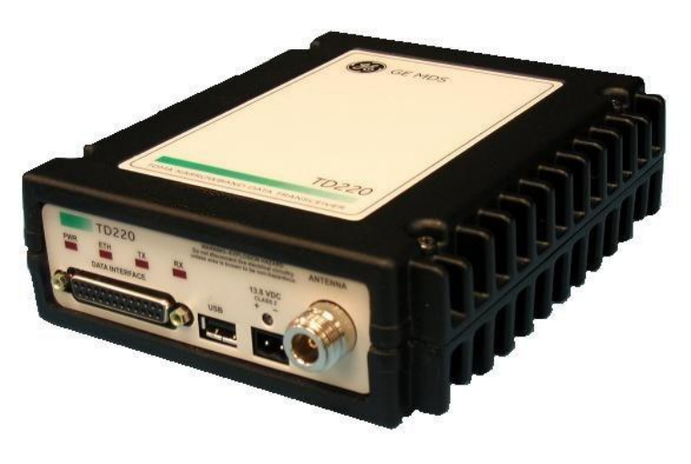
2 Introduction
The GE MDS TD220X is a 25-Watt 220 MHz GMSK data radio intended for bridging messages over
the air between locomotives and wayside devices in rail applications or between ship and shore in
maritime applications. The data interface is Ethernet and uses the UDP/IP-based Simple
Timeslot/Frequency/Power Protocol (STFP), defined elsewhere. STFP is capable of supporting various
payload protocols.
A time division channel access method is used by the TD220X for wireless communication. Each
second is divided into 8 133-byte time slots. The radio further defines a multi-second epoch to allow
the effective number of time slots to be scaled according to system design. Radios must be
configured with the same epoch size.
Precise synchronization of timing amongst radios is necessary for operation. Each radio can be
configured to use one of three timing sources: GPS, Precision Time Protocol (PTP), and over-the-air
(OTA). While system design can be flexible, a base radio installation typically uses either GPS or PTP
timing and a mobile radio typically uses OTA to synchronize to the wireless transmissions of a base
radio. Radios configured for GPS timing must be connected to an external GPS unit to receive NMEA
sentence information and the PPS signal. Radios configured for PTP timing will interact with a PTP
Grandmaster Clock over the Ethernet port using IEEE 1588 (PTPv2). Radios configured for OTA timing
use messages received wirelessly in the first time slot of each second to maintain timing.
With its time slot definition and variable epoch size, the TD220X provides a generic TDMA
implementation that can be used by an external Communication Manager (CM) to support a variety
of TDMA schemes. A CM is responsible for making decisions regarding timeslot, frequency, power,
and payload organization. The TD220X is responsible for requesting data from a CM for upcoming
timeslots, forwarding messages received wirelessly to a CM, and wirelessly transmitting messages
received from a CM using the specified timeslot, frequency, and power. All communication between
the TD220X and a CM is done using STFP.

TD220MAX_manual_v11.doc
05-6906A01 Page 6 of 49 7/31/2014
3 Interfaces
3.1 Data Interface (DB-25)
The Data Interface has several ports integrated into one connector: Ethernet, COM1 and COM2
Serial Ports, and GPS signaling. Note that COM3 is connected internally and therefore not available
on pins labeled with “COM3.”
DB-25
Pin
Signal
Direction WRT MDS
Equipment
Notes
1
COM3_DCD
Input
Reserved
2
COM2_TXD
Input
GPS NMEA Data Expected
3
COM2_RXD
Output
4
COM2_RTS
Input
5
COM2_CTS
Output
6
COM3_TXD
Output
Reserved
7
GND
Input/Output
8
COM2_DCD
Output
Used for aggregated alarm output, negative
voltage = no alarm, 0 voltage = radio off,
positive voltage = ALARM PRESENT. RS-232
Levels.
9
COM3_CTS
Input
Reserved
10
COM3_RTS
Output
Reserved
11
COM3_DTR
Output
Reserved
12
COM3_RXD
Input
Reserved
13
GND
Input/Output
14
ETH_TX_H
Output
15
ETH_TX_L
Output
16
ETH_RX_H
Input
17
ETH_RX_L
Input
18
EXT_KEY
Output
Reserved
19
EXT_DET
Input
Reserved
20
COM2_DTR
Input
21
ALARM_OUT
Output
Reserved
22
GPS_PPS_L
Input
Not Connected
23
GPS_PPS_H
Input
TTL level 1PPS signal input. 0 to 5 VDC nominal.
24
COM1_RXD
Input
Console
25
COM1_TXD
Output
Console
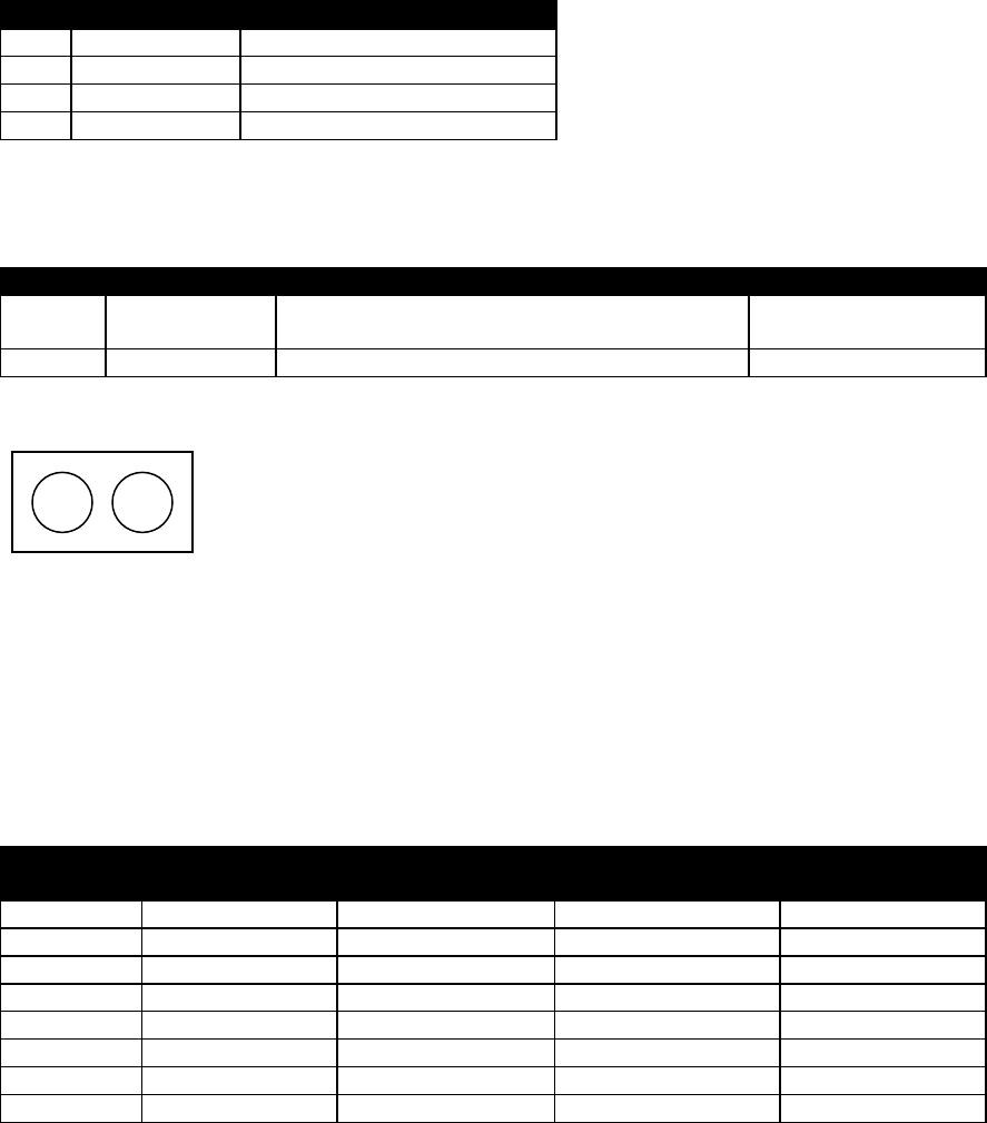
The DB-25 connector is female, and the orientation of the connector as looking into the front panel
of the unit is as shown below.
12 11 10 9 8 7 6 5 4 3 2 1
24 23 22 21 20 19 18 17 16 15 14
13
25
TD220MAX_manual_v11.doc
05-6906A01 Page 7 of 49 7/31/2014
3.2 USB
The radio provides a USB Port conforming to version 1.1 of the USB standard. This port is provided
for features such as logging STFP messages to text files on a memory stick. Consult GE MDS for
information on this feature. The pinout for this connector is given in the table below.
Pin
Signal Name
Description
1
PC_USB_+5V
+5 VDC
2
USBD-
USB Data Minus
3
USBD+
USB Data Plus
4
GROUND
Ground
3.3 Power
The power connector is a screw-secured 2-pin connector.
Pin
Signal Name
Direction with respect to MDS Equipment
Description
1 (L)
PWR
Input
13.8 VDC input, 7
Amps maximum.
2 (R)
GROUND
Input
Power return.
The pin orientation as looking into the connector is shown below.
Consult the following table to determine how much current is required for receiving or transmitting
vs. input voltage and RF power output. Duty cycle is a function of how many time slots of the 8 per
second are used for transmission. The STFP protocol used by the communications manager to send
data into the radio for transmission over the air specifies what time slot to use for each, so if the
communications manager uses all 8 slots, the duty cycle is 100%. If four are used every second, the
duty cycle is 50%. If 7 are used every 3 seconds (24 slots), the duty cycle is 29% (roughly 30%).
Many other duty cycles are possible depending on the epoch size and number of transmissions
within each epoch. If the duty cycle exceeds 29%, the RF output power is limited to 2 Watts. All MPE
RF safety calculations are based on the highest ERP levels.
Voltage (V)
RF Power Out
(W)
Duty Cycle (%)
Current Required
(A)
Thermal
Dissipation (W)
12
0 (RX)
0
0.3
TBSL
12
2
100
TBSL
TBSL
12
10
30
TBSL
TBSL
12
25
30
TBSL
TBSL
13.8
0 (RX)
0
0.3
TBSL
13.8
2
100
1.2
14
13.8
10
30
3.2
14
13.8
25
30
5.5
15
3.4 Antenna Connector
The Antenna Connector is a type N female connector with 50-Ohm characteristic impedance.
L
R

TD220MAX_manual_v11.doc
05-6906A01 Page 8 of 49 7/31/2014
Common Setup Tasks
Note: For accessing the COM1 console, use a serial terminal emulator program such as
HyperTerminal or Putty. The default settings are: baud rate 19200, no parity, 8 data bits, and 1 stop
bit. The pins for this port are listed in section 3.1.
4.1 Key the Transmitter for Test Purposes
1. Log in to the radio on its COM1 console using a serial terminal emulator program.
2. Go to the Radio Configuration menu.
3. Select the frequency for the test transmission.
4. Select the RF Output Power to use. Note that power levels greater than 2 Watts will
timeout after a 5-second period by default. Ensure ventilation with supplemental forced
airflow if longer durations are desired.
5. Select the Force TX Key menu option.
6. When finished, deselect the Force TX Key menu option.
4.2 Prepare the Network Interface for a Radio
Each radio is assigned an IP Address, a Netmask, and a Gateway IP Address. The IP Address and
Netmask should be chosen carefully. The radio will network directly with other equipment with IP
Addresses that are on a common Subnet. IP Addresses that begin with the same numerical IP
address bits where the Netmask is one will be on the same Subnet. For example, if the IP Address is
10.4.100.1 and the Netmask is 255.255.0.0, the radio will attempt direct Ethernet communication
with any node whose IP Address begins with 10.4. If a message is bound for a node outside of the
10.4 network, it will be sent to the Gateway IP address instead so that it can be placed from the
radio’s subnet onto another subnet.
1. Log in to the radio on its COM1 console using a serial terminal emulator program.
2. Go to the IP Configuration menu.
3. Set the IP address of the radio, plus the Netmask and Gateway.
4. Go to the Maintenance/Tools Menu and select the Ping Utility.
5. Enter the IP address of a known node on the network.
6. Execute the Ping and observe the results. If the network interface is working properly, Ping
responses should be received.
4.3 Upgrade the Firmware
4.3.1 Introduction
From time-to-time MDS will offer upgrades to the TD220X firmware. Uploading new firmware into
the radio does not require that the radio be taken off-line until you want to operate the radio from
the new firmware image. You must use the TD220X’s embedded Menu System for all firmware
activities, including uploading firmware from a TFTP server. The Menu System can be accessed in
one of two ways:
Terminal-Emulator—Use a terminal emulator program on your PC, such as HyperTerminal
or Putty, connected directly to the TD220X COM1 port via a serial cable.
Telnet—Text-based access to the Menu System through a network connection.
Firmware images are provided free-of-charge on the MDS Web site at:
http://supportcentral.ge.com/products/sup_products.asp?prod_id=181796

TD220MAX_manual_v11.doc
05-6906A01 Page 9 of 49 7/31/2014
4.3.2 Installing TD220X Firmware by TFTP
To use this function the user will need:
A PC with a TFTP server running.
The IP address of the PC running the TFTP server.
If you do not know your computer’s address on a Windows PC, you can use the RUN function from
the Start menu and enter winipcfg or ipcfg to determine your local PC’s IP address. The IP address of
the radio can be found on the Starting Information Screen. (See Page 24.) A TFTP server can be
found on the MDS web site at:
http://supportcentral.ge.com/products/sup_products.asp?prod_id=181796
4.3.3 Upload Procedure
To upload a new firmware file (tdx-krmd-X_Y_Z.mpk) into the TD220X unit use the following
procedure:
1. Launch a TFTP server on a PC connected either directly or via a LAN to the Ethernet port
(LAN) of the radio. On the Options tab, set the outgoing path to the directory containing the
firmware image file.
2. Connect to the radio’s Menu System by whichever means is convenient: Telnet via the LAN
or Terminal emulator via the COM1 port.
3. Go to the Reprogramming Menu.
(Starting Menu->Main Menu>Maintenance Menu>Reprogramming Menu)
4. Fill in the information for the:
o TFTP Host Address – IP Address of the server (host computer) running the TFTP
server.
o Retrieve File – Name of the file (tdx-krmd-X.Y.Z.mpk) to be pulled from the TFTP
server holding the firmware file.
5. Pull the firmware file through the TFTP server into the TD220X radio.
(Note: the uploaded firmware image file replaces the “Inactive Image” file and
be automatically verified.)
6. Reboot the TD220X radio.
7. Test the radio for normal operation.
8. End of procedure.
4.4 Set Up a GPS Base Unit
1. If not already done, complete steps from 4.2 above.
2. Connect the RS-232 NMEA serial data output from the GPS receiver to the Base Radio via
the radio’s COM2 port. Drive serial data into the radio on DB-25 pin 2.
3. Connect the GPS’s PPS output to the Base Radio. Drive TTL into the radio on DB-25 pin 23.
4. Log in to the radio.
5. Go to the GPS Configuration menu.
6. Verify that the GPS NMEA Baud Rate and PPS Polarity match the connected GPS.
7. Go to the System Configuration menu.
8. Set the timing source to GPS and reboot if necessary.
9. Set the STFP radio ID. Set to 64 (decimal) to match the configuration in the tests below.
10. Set the IP Port on which the base will receive STFP messages from the Communication
Manager.
11. Set the IP Address of the Communication Manager to which timing markers and messages
received from mobiles should be sent.
12. Set the epoch size to match the same value configured on the neighboring radios and
reboot if necessary.
13. Set the STFP slot delay as necessary. This number, multiplied by 125ms, represents the slot
delay allowed from when a timing marker is sent to the Communication Manager to when a
data message must be received from the Communication Manager. For most cases the
default value of 2 should suffice.
TD220MAX_manual_v11.doc
05-6906A01 Page 10 of 49 7/31/2014
14. Go to the Maintenance/Tools menu.
15. Verify the Ethernet Link using the Ping utility.
16. Begin sending UDP data.
17. Verify the TX LED illuminates and the radio begins transmitting over the air.
4.5 Set Up a PTP Base Unit
1. If not already done, complete steps from 4.2 above.
2. Install and configure a PTP Grandmaster Clock. The clock must be connected to the base
through the Ethernet Link. The base also communicates with the Communication Manager
using the Ethernet Link; therefore an external switch or router may be required.
3. Log in to the radio.
4. Go to the PTP Configuration menu.
5. Set the IP Port on which the base will receive PTP messages from the Grandmaster Clock.
6. Set the IP Address of the Grandmaster Clock.
7. Set the IP Port of the Grandmaster Clock.
8. Go to the System Configuration menu.
9. Set the timing source to PTP and reboot if necessary.
10. Set the STFP radio ID. Set to 64 (decimal) to match the configuration in the tests below.
11. Set the IP Port on which the base will receive STFP messages from the Communication
Manager.
12. Set the IP Address of the Communication Manager to which timing markers and messages
received from mobiles should be sent.
13. Set the IP Port of the Communication Manager to which timing markers and messages
received from mobiles should be sent.
14. Set the epoch size to match the same value configured on the neighboring radios and
reboot if necessary.
15. Set the STFP slot delay as necessary. This number, multiplied by 125ms, represents the slot
delay allowed from when a timing marker is sent to the Communication Manager to when a
data message must be received from the Communication Manager. For most cases the
default value of 2 should suffice.
16. Go to the Maintenance/Tools menu.
17. Verify the Ethernet Link using the Ping utility.
18. Begin sending UDP data.
19. Verify the TX LED illuminates and the radio begins transmitting over the air.
4.6 Set Up an OTA Mobile Unit
1. If not already done, complete steps from 4.2 above.
2. Log in to the radio.
3. Go to the System Configuration menu.
4. Set the timing source to OTA and reboot if necessary.
5. Set the STFP radio ID to 0 to match the configurations in the tests below.
6. Set the IP Port on which the mobile will receive STFP messages from the Communication
Manager.
7. Set the IP Address of the Communication Manager to which timing markers and messages
received from bases should be sent.
8. Set the IP Port of the Communication Manager to which timing markers and messages
received from bases should be sent.
9. Set the epoch size to match the same value configured on the neighboring radios and
reboot if necessary.
10. Set the STFP slot delay as necessary. This number, multiplied by 125ms, represents the slot
delay allowed from when a timing marker is sent to the Communication Manager to when a
data message must be received from the Communication Manager. For most cases the
default value of 2 should suffice.
TD220MAX_manual_v11.doc
05-6906A01 Page 11 of 49 7/31/2014
11. Go to the Maintenance/Tools menu.
12. Verify the Ethernet Link using the Ping utility.
13. Ensure at least one base is present in the neighborhood of this radio so that it can detect
beacons and synchronize timing.
14. Begin sending UDP data from a polling program.
15. Verify the TX LED illuminates and the radio begins transmitting over the air.
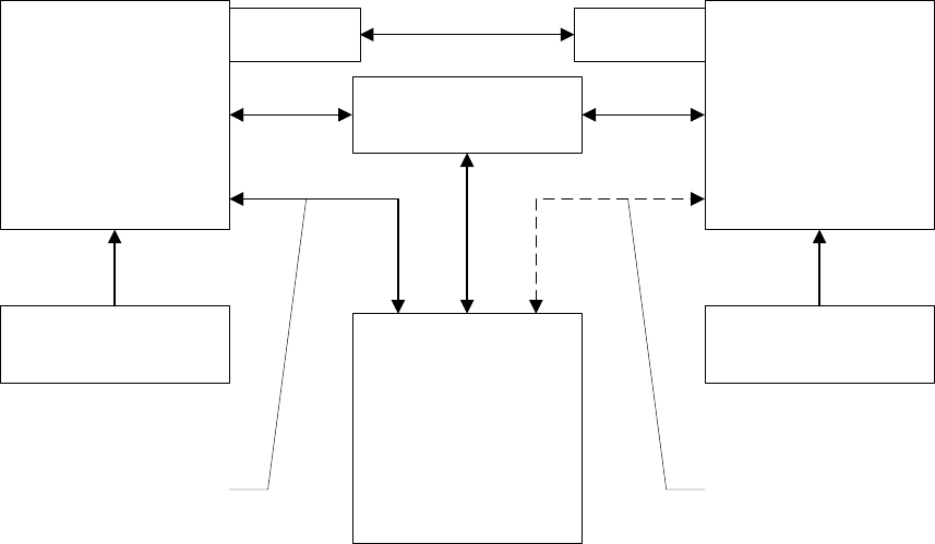
4.7 Perform Test Polling
1. Set up the Base and Mobile as above.
2. Connect as shown in the following diagram. Note: this is for bench testing only, i.e. not for
sensitivity testing. Sensitivity testing requires complete RF isolation or mixed operation to
prevent the leakage path from being the dominant RF path between units. For bench
testing, use attenuation so that the signal level at every unit that is participating is around
–70 to –50 dBm.
Test Polling Setup
TD220X Base
Set for 2 Watts TD220X mobile
Set for 2 Watts
Ethernet Switch
30 dB / 50W 30 dB / 50W
Test PC
13.8 VDC < 5 Amps 13.8 VDC < 5 Amps
Radio
COM1 to PC
Serial Port
Radio
COM1 to PC
Serial Port

TD220MAX_manual_v11.doc
05-6906A01 Page 12 of 49 7/31/2014
3. Configure the Base as follows:
System Configuration Menu
-==========================================================================-
A) Timing Source GPS
B) STFP Radio ID 64
C) STFP Receive Port 53000
D) STFP Transmit Address x.x.x.x (Note: Use IP address of Poller PC)
E) STFP Transmit Port 50000
F) STFP Epoch Size 6 sec
G) STFP Slot Delay 2
H) STFP Send OTA Beacon enabled
I) Timing Signal Timeout 60 Seconds
Select a letter to configure an item, <ESC> for the prev menu
Radio Configuration Menu
-==========================================================================-
A) Transmit Frequency 219.000000 MHz
B) Transmit Frequency 219.000000 MHz
C) Output Power 2 W
D) Enable External PA enabled
E) Max Message Age 60 sec
F) Force Tx Key Normal
TX Key Timeout 5 sec
Select a letter to configure an item, <ESC> for the prev menu
4. Reboot the Base
x dB

TD220MAX_manual_v11.doc
05-6906A01 Page 13 of 49 7/31/2014
5. Configure the Mobile as follows:
System Configuration Menu
-==========================================================================-
A) Timing Source OTA
B) STFP Radio ID 0
C) STFP Receive Port 53000
D) STFP Transmit Address x.x.x.x (Note: Use IP address of Poller PC)
E) STFP Transmit Port 50011
F) STFP Epoch Size 6 sec
G) STFP Slot Delay 2
H) STFP Send OTA Beacon disabled
I) Timing Signal Timeout 60 Seconds
Select a letter to configure an item, <ESC> for the prev menu
Radio Configuration Menu
-==========================================================================-
A) Transmit Frequency 219.000000 MHz
B) Transmit Frequency 219.000000 MHz
C) Output Power 2 W
D) Enable External PA enabled
E) Max Message Age 60 sec
F) Force Tx Key Normal
TX Key Timeout 5 sec
Select a letter to configure an item, <ESC> for the prev menu
6. Reboot the Mobile
7. Obtain the TD220X Poller (TD220X_Poller.exe) from GE MDS.
8. In the Poller directory, create or modify the TD220X poller data configuration file
(TD220X_Poller.parms) as shown below.
TD220MAX_manual_v11.doc
05-6906A01 Page 14 of 49 7/31/2014
set ::TXparms {
{ 0 "Type" 8 "00" "RW" }
{ 1 "Ver" 8 "09" "RW" }
{ 2 "Radio ID" 32 "00000040" "RW" }
{ 3 "Radio Cfg Tag" 8 "00" "RW" }
{ 4 "Timeslot" ts "07" "RW" }
{ 5 "TX Freq MHz" 32 "30323139" "RW" }
{ 6 "TX Freq kHz" 24 "303030" "RW" }
{ 7 "TX Freq Hz" 24 "303030" "RW" }
{ 8 "RX Freq MHz" 32 "30323139" "RW" }
{ 9 "RX Freq kHz" 24 "303030" "RW" }
{ 10 "RX Freq Hz" 24 "303030" "RW" }
{ 11 "TX Power" 8 "02" "RW" }
{ 12 "Length" l4 "00000000" "RO" }
{ 13 "Seq No" sn "00" "RW" }
{ 14 "Data" nt
"123456789012345678901234567890123456789012345678901234567890123456789012345678
9012345678901234567890123456789012345" "RW" }
{ 15 "CRC32" ck "00000000" "RO" }
}
set ::RXparms {
{ 0 "Type" 8 "00" "RW" }
{ 1 "Ver" 8 "09" "RW" }
{ 2 "Radio ID" 32 "00000000" "RW" }
{ 4 "Timeslot" ts "07" "RW" }
{ 5 "TX Freq MHz" 32 "30323139" "RW" }
{ 6 "TX Freq kHz" 24 "303030" "RW" }
{ 7 "TX Freq Hz" 24 "303030" "RW" }
{ 8 "RX Freq MHz" 32 "30323139" "RW" }
{ 9 "RX Freq kHz" 24 "303030" "RW" }
{ 10 "RX Freq Hz" 24 "303030" "RW" }
{ 11 "RSSI" rs "-120" "RW" }
{ 12 "Length" l4 "00000000" "RO" }
{ 13 "Seq No" sn "00" "RW" }
{ 14 "Data" nt
"123456789012345678901234567890123456789012345678901234567890123456789012345678
9012345678901234567890123456789012345" "RW" }
{ 15 "CRC32" ck "00000000" "RO" }
}
set ::ERparms {
{ 0 "Type" 8 "00" "RW" }
{ 1 "Ver" 8 "00" "RW" }
{ 2 "Radio ID" 32 "00000000" "RW" }
{ 4 "Timeslot" ts "07" "RW" }
{ 5 "TX Freq MHz" 32 "30323139" "RW" }
{ 6 "TX Freq kHz" 24 "303030" "RW" }
{ 7 "TX Freq Hz" 24 "303030" "RW" }
{ 8 "RX Freq MHz" 32 "30323139" "RW" }
{ 9 "RX Freq kHz" 24 "303030" "RW" }
{ 10 "RX Freq Hz" 24 "303030" "RW" }
{ 11 "RSSI" rs "-120" "RW" }
{ 12 "CRC32" ck "00000000" "RO" }
}
TD220MAX_manual_v11.doc
05-6906A01 Page 15 of 49 7/31/2014
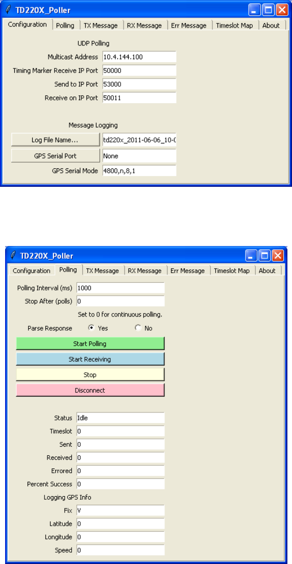
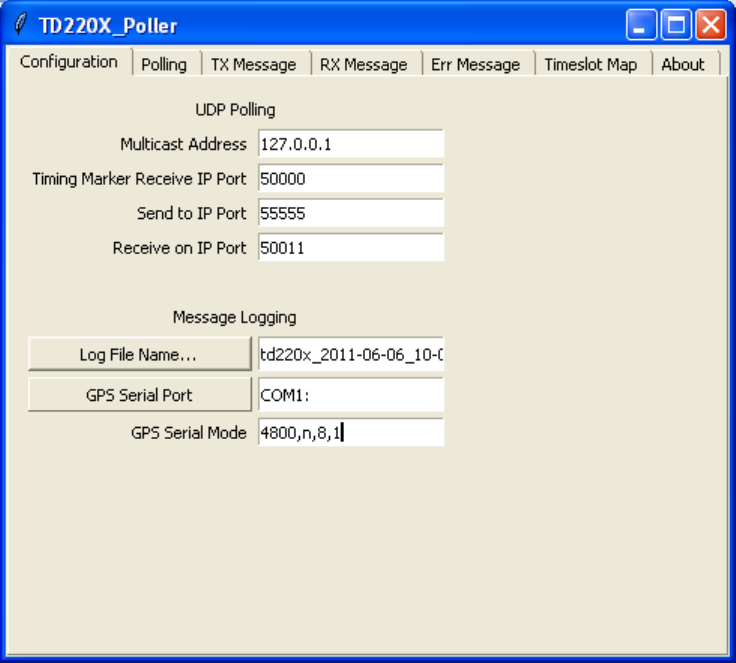
9. Set up the Poller as shown below, where 10.4.144.100 is replaced with the IP address of
your base radio. Note: Set GPS Serial Port to None to prevent the utility opening a serial
port.
10. Click Start Polling and observe the message counts and sequence number increment. The
test will show 100% success if all messages sent to the base radio were transmitted over
the air, received by the mobile radio, and forwarded back to the Poller.
TD220MAX_manual_v11.doc
05-6906A01 Page 16 of 49 7/31/2014
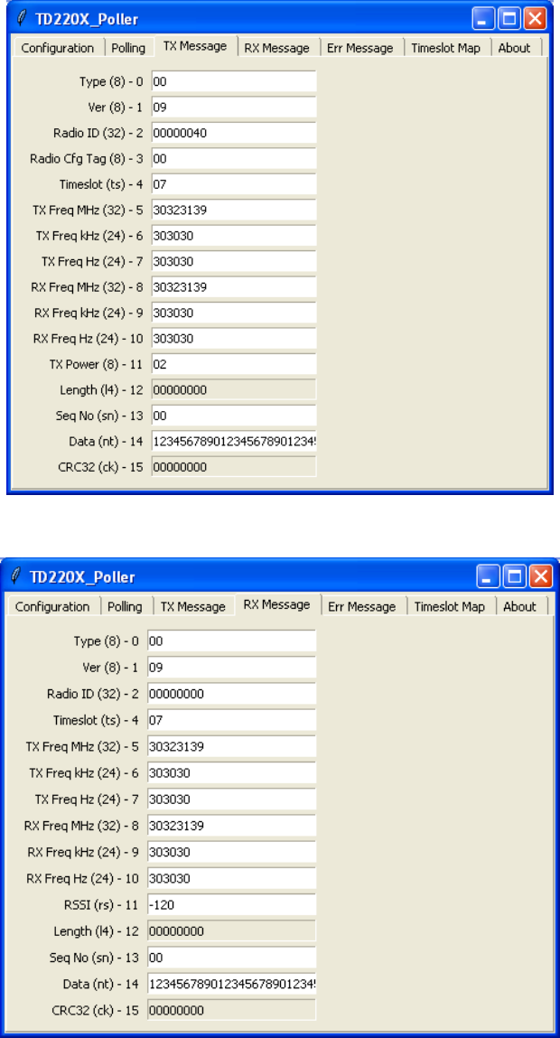
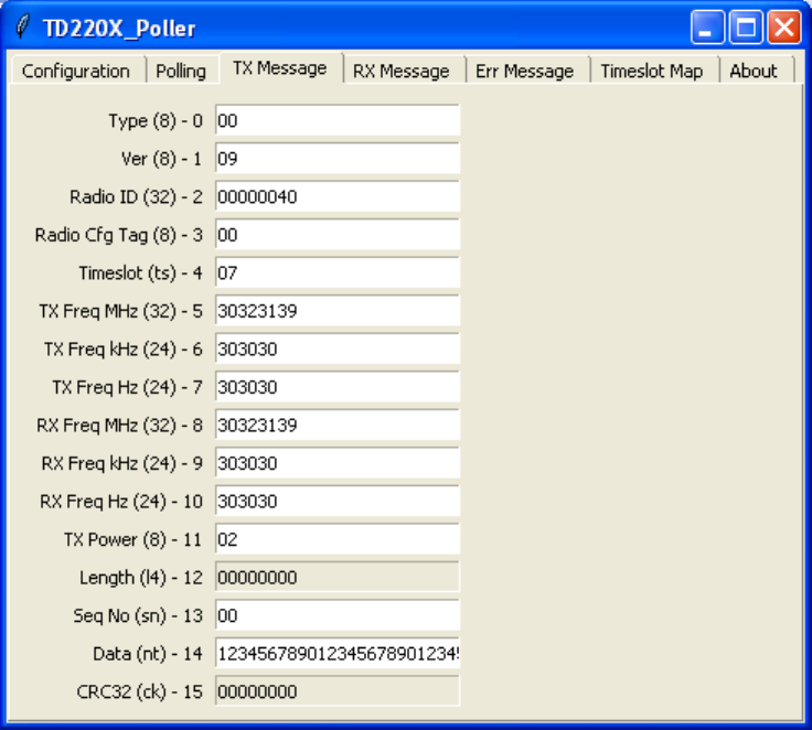
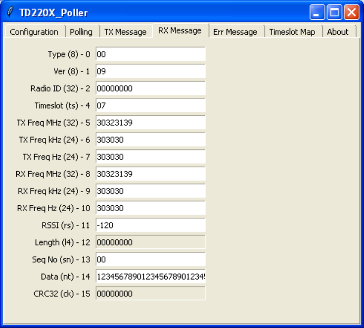
11. The TX Message tab updates as messages are sent to the base radio.
12. The RX Message tab updates as messages are received from the mobile radio.
TD220MAX_manual_v11.doc
05-6906A01 Page 17 of 49 7/31/2014
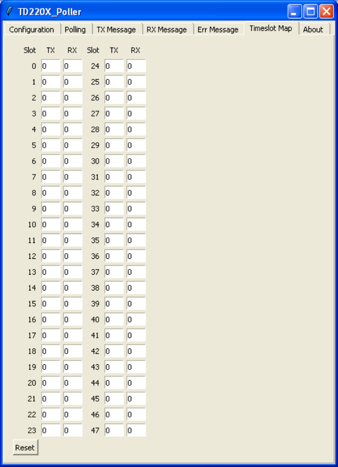
13. The Timeslot Map tab updates as messages are sent and received to show the distribution
of messages across the available timeslots. Note: Only 48 timeslots are shown,
supporting up to a 6 second epoch.
TD220MAX_manual_v11.doc
05-6906A01 Page 18 of 49 7/31/2014
4.8 Perform Field Survey
4.8.1 Set up the Base System
1. Set up a Base radio as above, using either a GPS or PTP timing configuration.
2. Erect a representative antenna system and connect the antenna system to the radio with
representative feedline.
3. Ensure the radio is supplied with sufficient DC power to accommodate the intended
transmit power setting.
4. Ensure you have a license to operate the radios and in the configuration settings below,
ensure the frequency setting matches your license.
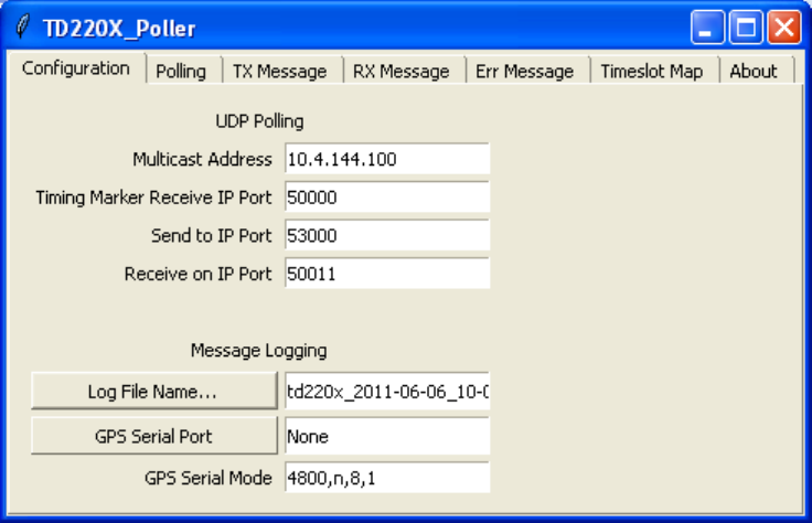
5. Run the Poller application on a PC at the fixed base location, setting it up according to the
screen shots below.
6. Once the Base Radio is set up properly, start polling.
Notes: Set the IP address to that of the Base Radio. Set “GPS Serial Port” to “None” to prevent the
base Poller from attempting to open communications with a GPS receiver. You can set the Receive
on IP Port to any value, because the base Poller will transmit only.
TD220MAX_manual_v11.doc
05-6906A01 Page 19 of 49 7/31/2014
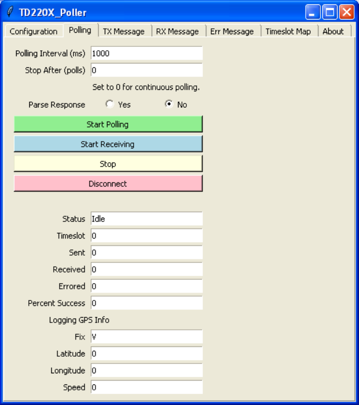
Notes: The Polling interval should be set to something fairly short to make sure the survey territory
is adequately painted, however setting it below 500 ms or so may exceed the transmit duty cycle of
the radio and/or overflow the radio’s input buffer and should be avoided. Setting “Stop After (polls)”
to zero causes the base Poller to continue transmitting messages indefinitely. “Parse Response”
can be set to “No” as the base Poller will transmit only.
TD220MAX_manual_v11.doc
05-6906A01 Page 20 of 49 7/31/2014
Note: Again, make sure you are authorized to transmit on the TX frequency you configure here.
Make sure the transmit power is appropriate for the survey you are undertaking. 2 Watts shown
above is the minimum power the radio puts out stand-alone. With an external PA, the radio is set to
2 Watts and the PA is adjusted to obtain the desired transmit power level. The power setting is in
hex, so 25 Watts would be entered as 19 for example.
TD220MAX_manual_v11.doc
05-6906A01 Page 21 of 49 7/31/2014
4.8.2 Set up the Mobile System
1. Set up the Mobile Radio as above, such that it obtains its system timing “OTA” or over the
air using beacons from the Base Radio.
2. Obtain a GPS receiver that can output NMEA serial messages to a portable PC for logging
purposes.
3. Configure the GPS receiver to output only $GPRMC sentences.
4. Run the Poller application on a portable PC or laptop to travel with the mobile radio.
5. Set up the mobile Poller application as shown in the following screen shots.
6. When you start the test from the Mobile Poller application, use the “Start Receiving” button
instead of the “Start Polling” button. This puts the utility into receive-only mode.
Notes: You should set the mobile Poller to send to the portable PC’s IP address (or 127.0.0.1) and
an unused port like 55555 because the mobile radio is not intended to transmit for this test. Set
the mobile Poller to log to the desired file. This file will contain your survey data including date,
time, GPS location and received signal strength. Set the Poller application to accept GPS NMEA
data from a GPS receiver via the appropriate serial port and mode.
TD220MAX_manual_v11.doc
05-6906A01 Page 22 of 49 7/31/2014
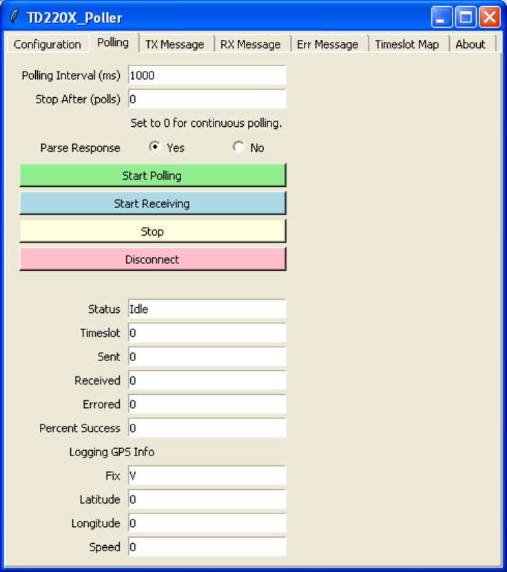
Notes: Set the mobile Poller’s “Stop After (polls)” value to zero to cause it to run until stopped
manually. Set the mobile Poller’s “Parse Response” field to “Yes”.
TD220MAX_manual_v11.doc
05-6906A01 Page 23 of 49 7/31/2014
Notes: Make sure the RX Message tab looks like this. This tab is set up via the
TD220X_Poller.parms file as shown above.
TD220MAX_manual_v11.doc
05-6906A01 Page 24 of 49 7/31/2014
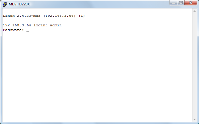
5 Menu Interface
Login with the administrator user name and password
TD220MAX_manual_v11.doc
05-6906A01 Page 25 of 49 7/31/2014
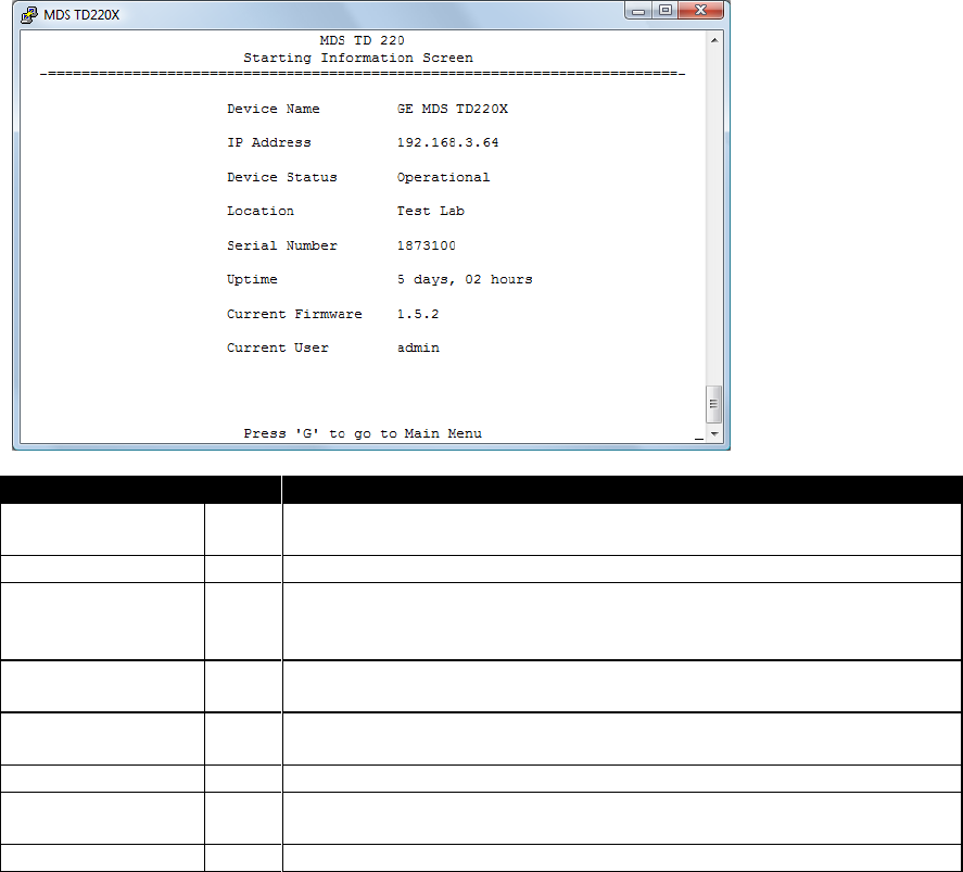
When logged in, the Starting Information Screen is displayed.
Parameter
R/W
Description
Device Name
R*
User-configured name for this radio. Set this from the Device Names
menu.
IP Address
R*
IP Address for this radio. Set this from the IP Networking menu.
Device Status
R
“Initializing” during startup and/or internal RF deck reprogramming,
“Operational” when functioning, “Alarmed” when error condition(s)
exist.
Location
R*
User-configured location for this radio. Set this from the Device
Names menu.
Serial Number
R
The manufacturer’s serial number for this radio. Set only in the
factory.
Uptime
R
Elapsed time since the radio was started.
Current Firmware
R*
The version number of the currently operating firmware. Reprogram
firmware from the Reprogramming Menu.
Current User
R
Login level.
R* - This parameter is writable from another menu.
TD220MAX_manual_v11.doc
05-6906A01 Page 26 of 49 7/31/2014
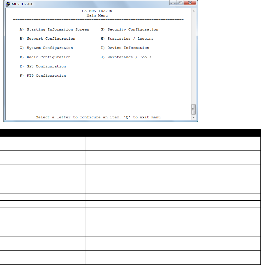
5.1 Main Menu
Parameter
R/W
Description
A) Starting Information
Screen
Returns to the opening menu.
B) Network
Configuration
Set the radio’s IP Address, Netmask, and Gateway.
C) System
Configuration
Set the radio’s timing source (GPS/PTP/OTA) and other
application-specific operating parameters.
D) Radio Configuration
Set the radio’s Frequencies, RF Power Output, External PA Enable
and access the Force TX Key function.
E) GPS Configuration
Set up the GPS NMEA and PPS connections
F) PTP Configuration
Set up the Precision Time Protocol (PTP) configuration.
G) Security
Configuration
Set up how the radio may be accessed.
H) Statistics / Logging
Obtain historical and current statistics about the radio’s payload
performance, and access STFP Logging configuration.
I) Device Information
Set up the radio’s Date, Time, Console Baud Rate and Names.
Review the radio’s Model, Serial Number, and Uptime.
J) Maintenance / Tools
Access the radio’s Firmware Reprogramming, Configuration
Script, and Ping Utility menus.
TD220MAX_manual_v11.doc
05-6906A01 Page 27 of 49 7/31/2014
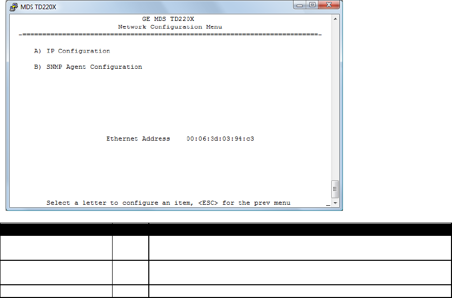
5.2 Network Configuration Menus
Parameter
R/W
Description
A) IP Configuration
Access the IP Configuration menu to set the IP Address, Netmask,
and Gateway IP Address.
B) SNMP Agent
Configuration
Access the SNMP Agent Configuration Menu.
Ethernet Address
R
Displays the hardware MAC address for the Ethernet port.
TD220MAX_manual_v11.doc
05-6906A01 Page 28 of 49 7/31/2014
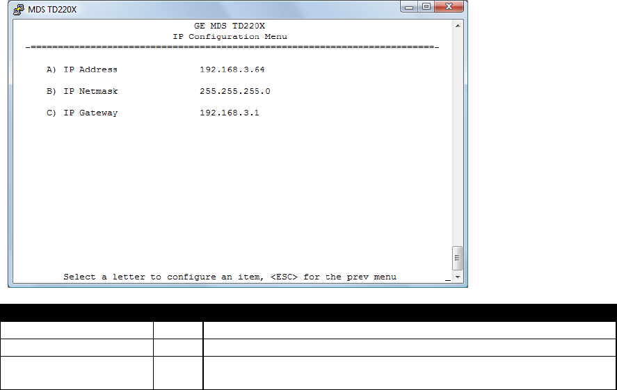
Parameter
R/W
Description
A) IP Address
R/W
The IP address that this radio will use for its Ethernet interface.
B) IP Netmask
R/W
The subnet mask for the network this radio is part of.
C) IP Gateway
R/W
The IP address of the gateway that will pass traffic from the
radio’s subnet to nodes on other networks.
Note: The IP Address and IP Gateway must be on the same subnet or a Network Interface error will
occur.
TD220MAX_manual_v11.doc
05-6906A01 Page 29 of 49 7/31/2014
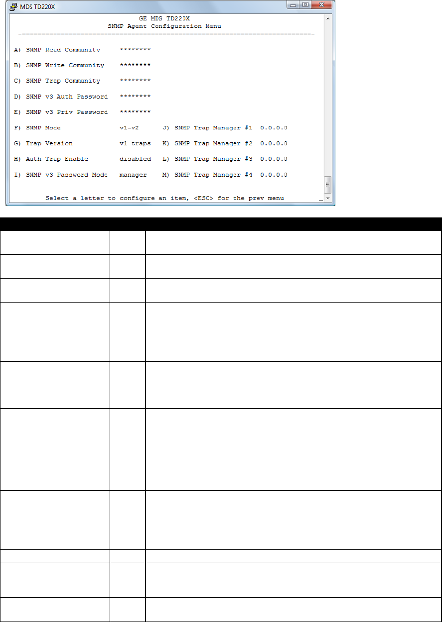
Parameter
R/W
Description
A) SNMP Read
Community
R/W
SNMP community string used for SNMPv1/SNMPv2c read access.
This string can be up to 30 alphanumeric characters.
B) SNMP Write
Community
R/W
SNMP community string used for SNMPv1/SNMPv2c write access.
This string can be up to 30 alphanumeric characters.
C) SNMP Trap
Community
R/W
SNMP community string used for SNMPv1/SNMPv2c trap access.
This string can be up to 30 alphanumeric characters.
D) SNMP v3 Auth
Password
R/W
Authentication password stored in flash. Will be used when Agent
is managing passwords locally or initially for all cases on reboot.
This is the SNMPv3 password used for Authentication (currently
only MD5 is supported). This string can be up to 30 alphanumeric
characters.
E) SNMP v3 Priv
Password
R/W
Privacy password stored in flash. Will be used when Agent is
managing passwords locally or initially for all cases on reboot.
This is the SNMPv3 password used for Privacy (DES encryption).
This string can be between 8 and 30 alphanumeric characters.
F) SNMP Mode
R/W
This specifies the mode of operation of the SNMP Agent. Choices
are disabled, v1_only, v2_only, v3_only, v1-v2, and v1-v2-v3. If the
mode is disabled, then the Agent will not respond to any SNMP
traffic. If the mode is v1_only, v2_only, or v3_only, then the Agent
will only respond to that version of SNMP traffic. If the mode is v1-
v2, or v1-v2-v3, then the Agent will respond to the specified
version of SNMP traffic. The default mode is v1-v2-v3 (trilingual).
G) Trap Version
R/W
This specifies what version of SNMP will be used to encode the
outgoing traps. The different versions of SNMP will include
different information in the traps. The choices are v1_traps,
v2_trap, and v3_traps. When v3_traps are selected, v2-style traps
will be sent but with a v3 header.
H) Auth Trap Enable
R/W
Indicates whether or not traps will be generated for login events.
I) SNMP v3 Password
Mode
R/W
Determines whether v3 passwords are managed locally or via an
SNMP Manager. The different behaviors of the Agent depending
on the mode specified here are described above.
J) SNMP Trap Manager
#1
R/W
Specifies an SNMP Manager on the network that traps will be sent
to.

TD220MAX_manual_v11.doc
05-6906A01 Page 30 of 49 7/31/2014
Parameter
R/W
Description
K) SNMP Trap Manager
#2
R/W
Specifies an SNMP Manager on the network that traps will be sent
to.
L) SNMP Trap Manager
#3
R/W
Specifies an SNMP Manager on the network that traps will be sent
to.
M) SNMP Trap
Manager #4
R/W
Specifies an SNMP Manager on the network that traps will be sent
to.
TD220MAX_manual_v11.doc
05-6906A01 Page 31 of 49 7/31/2014
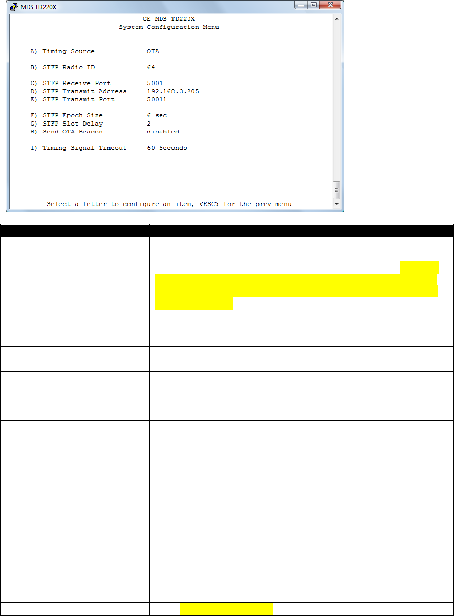
5.3 System Configuration Menu
Parameter
R/W
Description
A) Timing Source
R/W
The timing source used by the radio to precisely determine
current time and the start of each second. Valid values are Global
Positioning System (GPS), Precision Time Protocol (PTP), GPS with
PTP fallback, PTP with GPS fallback, and over-the-air (OTA). Base
radios are configured for GPS, PTP, GPS with PTP fallback, or PTP
with GPS fallback. Mobile radios are configured for OTA. An OTA
radio requires either a GPS or PTP radio within range in order to
synchronize timing.
B) STFP Radio ID
R/W
Uniquely identifies the radio to the Communication Manager.
C) STFP Receive Port
R/W
This IP Port is used to receive STFP messages from the
Communication Manager.
D) STFP Transmit
Address
R/W
This is the IP Address of the Communication Manager.
E) STFP Transmit Port
R/W
This is the IP Port used by the Communication Manager to receive
STFP messages from the radio.
F) STFP Epoch Size
R/W
This is the number of seconds constituting an epoch. Valid values
are 1, 2, 3, 4, 5, 6, 10, 12, 15, 20, and 30. The number of timeslots
equals 8 times the epoch size chosen. Note: This parameter must
match for all radios communicating.
G) STFP Slot Delay
R/W
This is the number of slots (125ms each) in advance that the radio
will request data from the Communication Manager. This delay
encompasses the time needed for timing markers to transit the
network, processing by the Communication Manager, and
resulting payload messages to transit the network.
H) Send OTA Beacon
R/W
This parameter requests the radio to transmit beacons in the first
time slot of each second when no message is received from the
Communication Manager for the time slot. Beacons are required
to maintain OTA timing of mobiles. Note: This parameter is
ignored and no beacons are sent when the timing source is set
to OTA.
I) Timing Signal
R/W
If the selected timing input is missing for this duration, the radio
TD220MAX_manual_v11.doc
05-6906A01 Page 32 of 49 7/31/2014
Timeout
asserts an alarm and if configured fails over to the selected
alternate timing source.
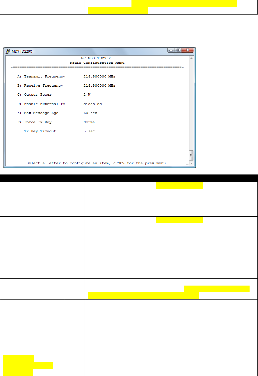
5.4 Radio Configuration Menu
Parameter
R/W
Description
A) Transmit Frequency
R/W
The initial frequency in the 216.0 to 221.99875 MHz range that the
radio uses for over the air transmissions upon booting. Note: STFP
messages specify the frequency to be used when transmitting.
This parameter is ignored once an STFP message has been
received.
B) Receive Frequency
R/W
The initial frequency in the 216.0 to 221.99875 MHz range that the
radio uses for receiving over the air transmissions upon booting.
Note: STFP messages specify the frequency to be used when
receiving. This parameter is ignored once an STFP message has
been received.
C) Output Power
R/W
The RF Output Power from 2 to 25 Watts with which the radio
transmits. Note: STFP messages specify the power to be used
when transmitting. This parameter is ignored once an STFP
message has been received.
D) Enable External PA
R/W
If enabled the radio ignores per message power values specified
by STFP and forces transmissions at a lower power level suitable
for driving the external PA (around 200 mW).
E) Max Message Age
R/W
The maximum age a transmit message can remain in the queue
before it is dropped. This time is measured from when the
message is received via UDP until it is about to be placed into a
packet for transmission OTA.
F) Force TX Key
R/W
“Normal” to allow the radio to operate in data mode, “Forced” to
key the transmitter for test purposes.
TX Key Timeout
R
If TX Key is Forced, the radio will automatically De-Key after this
timeout.
Need to add
information on duty
cycle setup.
TD220MAX_manual_v11.doc
05-6906A01 Page 33 of 49 7/31/2014
TD220MAX_manual_v11.doc
05-6906A01 Page 34 of 49 7/31/2014
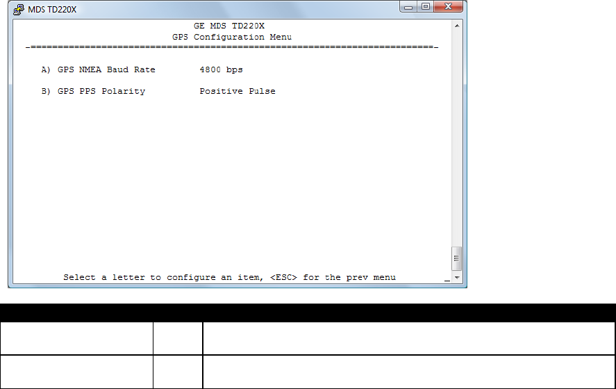
5.5 GPS Configuration Menu
Parameter
R/W
Description
A) GPS NMEA Baud
Rate
R/W
This is the Baud Rate used on the radio port to receive NMEA
Sentences.
B) GPS PPS Polarity
R/W
Indicates if the TTL PPS Pulse is Active High (Positive Pulse) or
Active Low (Negative Pulse).
TD220MAX_manual_v11.doc
05-6906A01 Page 35 of 49 7/31/2014
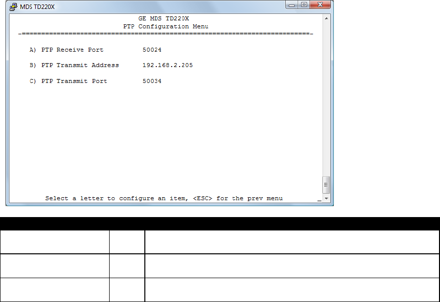
5.6 PTP Configuration Menu
Parameter
R/W
Description
A) PTP Receive Port
R/W
This IP Port is used by the radio to receive messages from the PTP
grandmaster Clock.
B) PTP Transmit
Address
R/W
This is the IP Address of the PTP Grandmaster Clock to which the
radio will send PTP messages.
C) PTP Transmit Port
R/W
This is the IP Port of the PTP Grandmaster Clock to which the radio
will send PTP messages.
TD220MAX_manual_v11.doc
05-6906A01 Page 36 of 49 7/31/2014
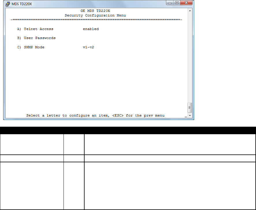
5.7 Security Configuration Menu
Parameter
R/W
Description
A) Telnet Access
R/W
If “enabled”, the radio allows users to Telnet to the radio via
Ethernet. If “disabled”, users must manage the radio via SNMP or
the serial console.
B) User Passwords
Allows modification of the admin password.
F) SNMP Mode
R/W
This specifies the mode of operation of the SNMP Agent. Choices
are disabled, v1_only, v2_only, v3_only, v1-v2, and v1-v2-v3. If the
mode is disabled, then the Agent will not respond to any SNMP
traffic. If the mode is v1_only, v2_only, or v3_only, then the Agent
will only respond to that version of SNMP traffic. If the mode is v1-
v2, or v1-v2-v3, then the Agent will respond to the specified
version of SNMP traffic. The default mode is v1-v2-v3 (trilingual).
TD220MAX_manual_v11.doc
05-6906A01 Page 37 of 49 7/31/2014
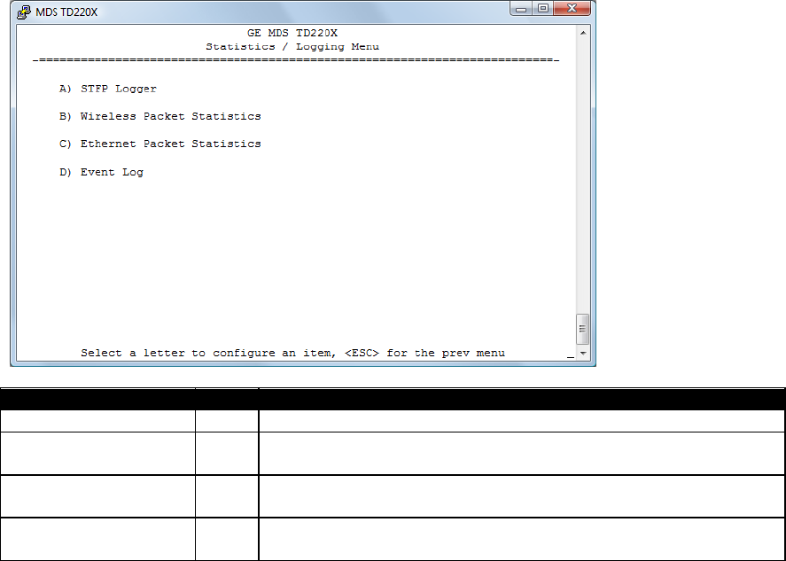
5.8 Statistics/Logging Menus
Parameter
R/W
Description
A) STFP Logger
Access the STFP Logger menu.
B) Wireless Packet
Statistics
Access the Wireless Packet Statistics menu where you can view
the number of messages passed over the air.
C) Ethernet Packet
Statistics
Access the Ethernet Packet Statistics menu where you can view
the number of messages passed via Ethernet.
D) Event Log
Access the Event Log menu where you can view the radio’s log of
system events and alarms.
TD220MAX_manual_v11.doc
05-6906A01 Page 38 of 49 7/31/2014
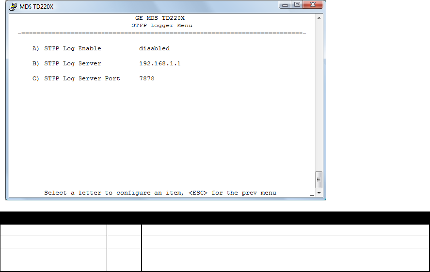
Parameter
R/W
Description
A) STFP Log Enable
R/W
If “enabled”, the radio will send UDP messages to a logging host.
B) STFP Log Server
R/W
The IP address to send UDP messages for logging STFP traffic.
C) STFP Log Server
Port
R/W
The IP port number to send UDP messages for logging STFP traffic.
TD220MAX_manual_v11.doc
05-6906A01 Page 39 of 49 7/31/2014
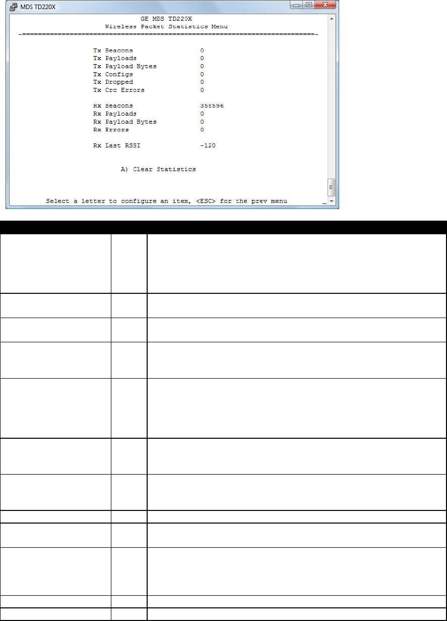
Parameter
R/W
Description
Tx Beacons
R
The number of beacon messages transmitted over the air. Beacon
messages are messages sent in the first time slot of a second that
contain no payload. If a message with payload is sent during the
first time slot of a second, it is still used by OTA radios to
synchronize time but it is not included in this statistic.
Tx Payloads
R
The number of packets containing payload transmitted over the
air.
Tx Payload Bytes
R
The number of bytes for all packets containing payload
transmitted over the air.
Tx Configs
R
The number of STFP configuration messages processed by the
radio. STFP configuration messages are used to change the radio
receive and transmit frequencies.
Tx Dropped
R
The number of packets to be transmitted over the air that were
dropped by the radio before sending. There can be various
reasons for this. For example, an STFP message could not be
properly decoded by the radio, or a message could not be
transmitted because the radio is in an alarm state.
Tx Crc Errors
R
The number of packets to be transmitted over the air that were
dropped by the radio before sending because the STFP CRC did
not match.
Rx Beacons
R
The number of beacon messages received over the air. Beacon
messages are messages sent in the first time slot of a second that
contain no payload.
Rx Payloads
R
The number of packets containing payload received over the air.
Rx Payload Bytes
R
The number of bytes for all packets containing payload received
over the air.
Rx Errors
R
The number of packets received over the air for which the radio
detected an error that could not be compensated for using
forward error correction. This will match the number of STFP error
messages generated by the radio.
Rx Last RSSI
R
The RSSI of the last message received.
A) Clear Statistics
Reset all results to zero.
TD220MAX_manual_v11.doc
05-6906A01 Page 40 of 49 7/31/2014
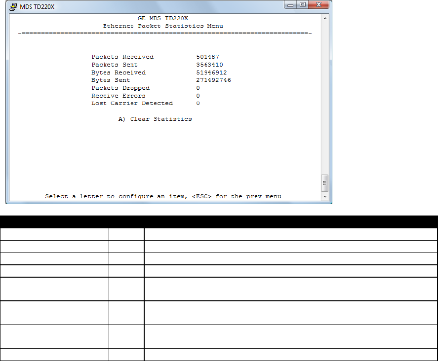
Parameter
R/W
Description
Packets Received
R
The number of packets received over Ethernet.
Packet Sent
R
The number of packets transmitted over Ethernet.
Bytes Received
R
The number of bytes for all packets received over Ethernet.
Bytes Sent
R
The number of bytes for all packets transmitted over Ethernet.
Packets Dropped
R
The number of packets that were dropped due to the Ethernet
interface being busy.
Receive Errors
R
The number of messages received over Ethernet that did not
decode properly.
Lost Carrier Detected
R
The number of times a message could not be sent over Ethernet
because the cable was unplugged.
A) Clear Statistics
Reset all results to zero.
TD220MAX_manual_v11.doc
05-6906A01 Page 41 of 49 7/31/2014
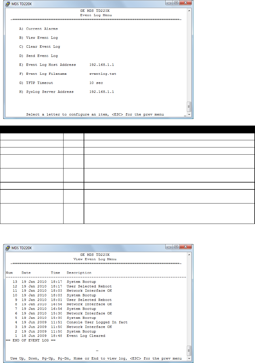
Parameter
R/W
Description
A) Current Alarms
Display a list of the alarms currently active within the radio.
B) View Event Log
Scroll through the historical list of radio events and alarms.
C) Clear Event Log
Erase all history of radio events and alarms.
D) Send Event Log
Begin a TFTP transfer of the historical list of all radio events to the
IP Address given by “Event Log Host Address”.
E) Event Log Host
Address
R/W
The IP Address of the server that will accept TFTP transfer of the
Event Log.
F) Event Log Filename
R/W
The file name on the server for the event log.
G) TFTP Timeout
R/W
If the radio cannot reach the TFTP server, it waits this long before
giving up at each step in the process.
H) Syslog Server
Address
R/W
As events and alarms occur in real time, send them via the
standard SYSLOG protocol (RFC 3164) to the server at this IP
Address.
This screen displays the event number, date and time, and event or alarm for each occurrence.
TD220MAX_manual_v11.doc
05-6906A01 Page 42 of 49 7/31/2014
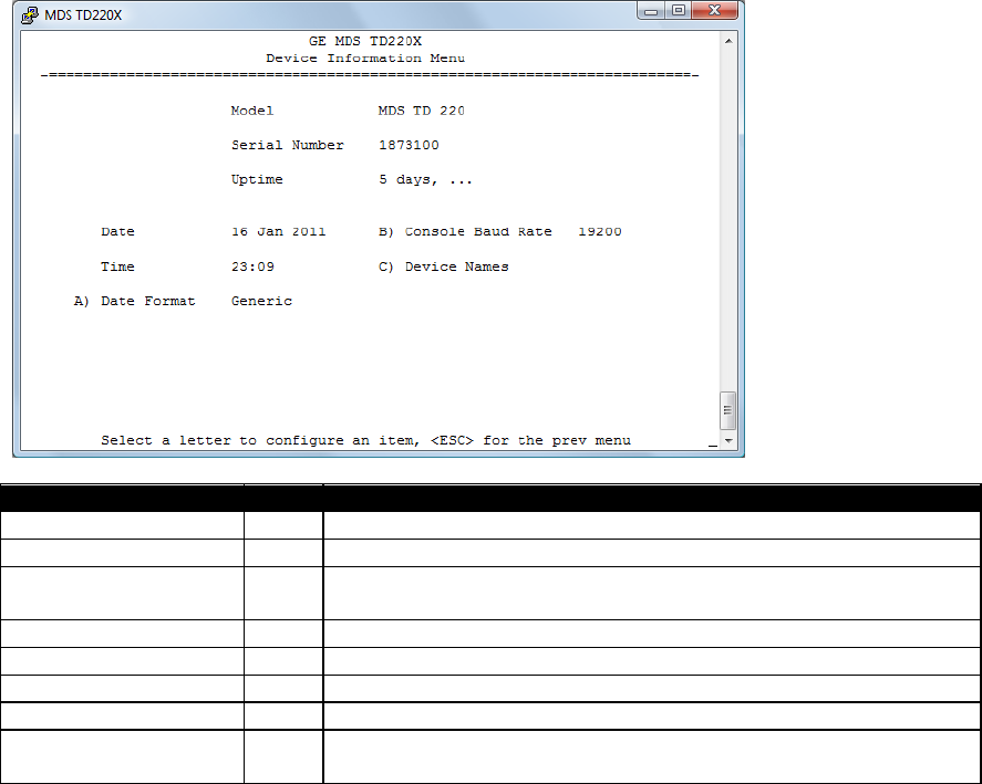
5.9 Device Information Menus
Parameter
R/W
Description
Model
R
The Model Type of the radio.
Serial Number
R
The factory-assigned unique radio Serial Number.
Uptime
R
The number of elapsed hours, minutes, and seconds since the
radio last rebooted.
Date
R
The Date from the GPS receiver.
Time
R
The Time from the GPS receiver.
A) Date Format
R/W
Change how the date and time are displayed.
B) Console Baud Rate
R/W
The serial port rate the console will communicate at.
C) Device Names
Access the Device Names menu where you can modify the user-
programmable name strings for this radio.
TD220MAX_manual_v11.doc
05-6906A01 Page 43 of 49 7/31/2014
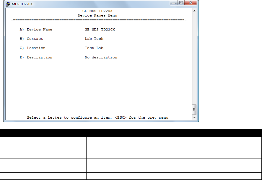
Parameter
R/W
Description
A) Device Name
R/W
Free-form field where you can enter a nickname for this radio.
B) Contact
R/W
Free-form field where you can indicate who to contact in case the
radio needs service.
C) Location
R/W
Free-form field where you can describe the site at which the radio
is installed.
D) Description
R/W
Free-form field where you can enter details describing this radio.
TD220MAX_manual_v11.doc
05-6906A01 Page 44 of 49 7/31/2014
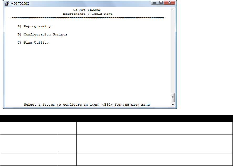
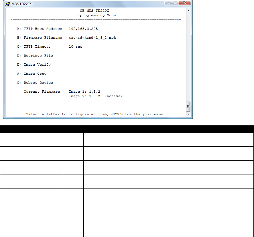
5.10 Maintenance/Tools Menus
Parameter
R/W
Description
A) Reprogramming
Access the Reprogramming menu where you can upgrade the
radio’s firmware.
B) Configuration
Scripts
Access the Configuration Scripts menu where you can save and
restore the radio’s configuration to and from a text file via a TFTP
server.
C) Ping Utility
Access the Ping Utility menu where you can confirm Ethernet
communications with one or more hosts.
TD220MAX_manual_v11.doc
05-6906A01 Page 45 of 49 7/31/2014
Parameter
R/W
Description
A) TFTP Host Address
R/W
The IP address of the TFTP server from which you will download a
new firmware image.
B) Firmware Filename
R/W
The file name for the firmware image. This file must exist on the
server.
C) TFTP Timeout
R/W
If the radio cannot reach the TFTP server, it waits this long before
giving up at each step in the process.
D) Retrieve File
Command the radio to request the firmware image from the TFTP
server.
E) Image Verify
Command the radio to perform a check of the firmware image in
memory.
F) Image Copy
Command the radio to copy the active firmware image to the
inactive position.
G) Reboot Device
Command the radio to restart using one of the firmware images.
Current Firmware
Shows the version number of both firmware images, plus which
one is currently executing.
TD220MAX_manual_v11.doc
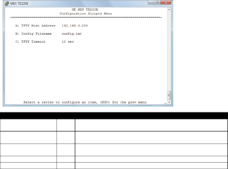
05-6906A01 Page 46 of 49 7/31/2014
Parameter
R/W
Description
A) TFTP Host Address
R/W
The IP address of the TFTP server to or from which you will upload
or download a configuration script.
B) Config Filename
R/W
The filename to or from which you will save or restore the radio’s
configuration.
C) TFTP Timeout
R/W
If the radio cannot reach the TFTP server, it waits this long before
giving up at each step in the process.
D) Retrieve File
Command the radio to get the file from the TFTP server.
E) Send File
Command the radio to send the file to the TFTP server.
Configuration scripts are used to store and duplicate radio settings. To use this facility, send the
configuration file from a radio to the TFTP server. It can then be archived or edited and retrieved
from the same or different radios. For more information, contact GE MDS.
TD220MAX_manual_v11.doc
05-6906A01 Page 47 of 49 7/31/2014
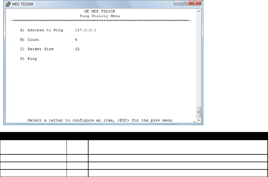
Parameter
R/W
Description
A) Address to Ping
R/W
The IP address of the network host to which you will send test
messages.
B) Count
R/W
The number of test messages you will send.
C) Packet Size
R/W
The number of Bytes each test message will contain.
D) Ping
Command the radio to begin the ping test.

TD220MAX_manual_v11.doc
05-6906A01 Page 48 of 49 7/31/2014
6 Troubleshooting
Here are some tips to help resolve issues when operating the TD220X.
Symptom
Possible Cause
Radio is alarmed (PWR LED is flashing)
Check the alarm list accessible from the Starting
Information Screen.
Alarm: GPS PPS Not Available
Radio is not receiving a PPS.
Alarm: GPS Signal Inverted
Although a PPS has been detected, it is in the
ACTIVE state for more than a half of a second.
Try switching the PPS Polarity setting on the GPS
Configuration Menu.
Alarm: NMEA Data – Invalid
The radio is not receiving valid NMEA GGA
Sentences. Verify that the NMEA Baud rate is set
correctly and verify that the GPS is outputting
ASCII GGA sentences (and no others, if possible).
Alarm: OTA Sync Lost
The radio has lost over the air synchronization
because it is no longer receiving wireless
beacons from a GPS or PTP radio.
Alarm: PTP Sync Lost
The radio is not receiving time updates from the
configured PTP Grandmaster Clock.
Radio shows messages are received via
Ethernet, but it will not transmit over the air.
Radio is alarmed.

TD220MAX_manual_v11.doc
05-6906A01 Page 49 of 49 7/31/2014
7 Change Log
Version
Date
Author
Changes
1
1/17/2011
L. Lowe
Initial release for TD220X
2
1/20/2011
T. Mayo
Updated FCC notices
Updated power supply current requirements
3
2/15/2011
T. Mayo
Clarified 1PPS input levels.
4
2/24/2011
T. Mayo
Updated screenshots for the Poller application.
Added a section on field surveying using the Poller
application.
5
2/28/2011
T. Mayo
Removed references to Parm Poller, the old name for
TD220X Poller.
6
3/7/2011
K. Tuttle
Added the “Upgrading the Firmware” section
7
6/6/2011
T. Mayo
Adjusted parts of the bench and field test sections to
make configuration more foolproof.
8
5/15/2012
T. Mayo
Added information on COM1 port defaults.
Changed links to point to Support Central.
9
7/30/2014
T. Mayo
Added information for DB-25 aggregated alarm output
(pin 8).
Added information for fallback timing sources.
Corrected frequency ranges for Radio Configuration
menu.
Need to add information on duty cycle setup.
Made corrections based on agency compliance
feedback.
10
7/30/2014
T. Mayo
Added part number.
11
7/31/2014
T. Mayo
Clarified duty cycle information.