GE MDS DS-TRM220SB TRM220SB User Manual Book3
GE MDS LLC TRM220SB Book3
UserManual.wiki
>
GE MDS
>
DS TRM220SB User Manual
User Manual
Navigation menu
Upload a User Manual
Namespaces
Wiki Guide
HTML
PDF
Info
Views
User Manual
Discussion / Help
Navigation
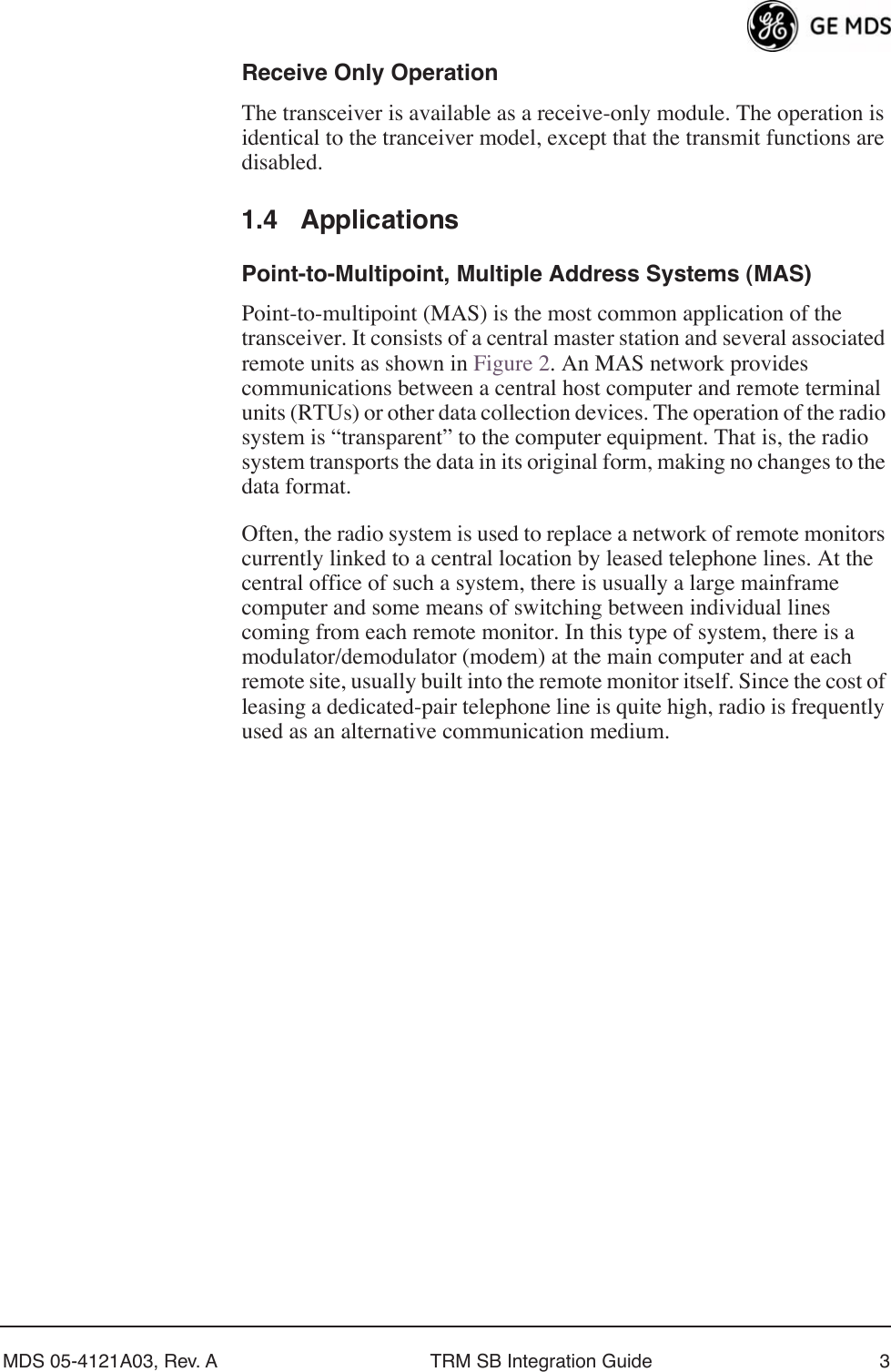
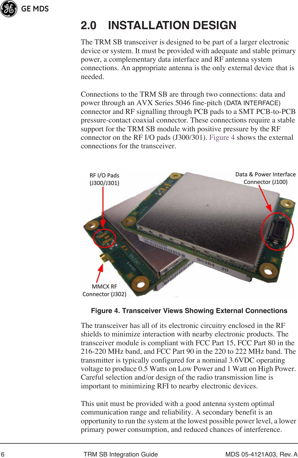
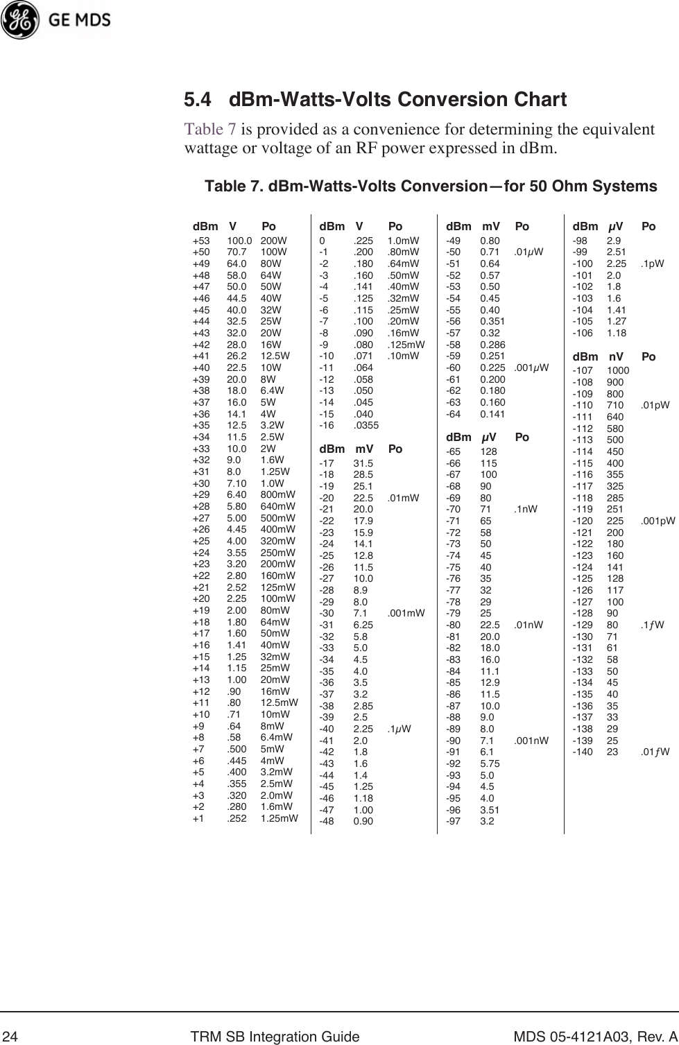
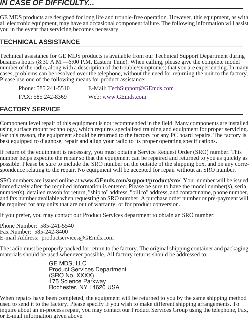
![MDS 05-4121A03, Rev. A TRM SB Integration Guide 133.0 TRANSCEIVER CONFIGURATION AND DIAGNOSTIC COMMANDSThe transceiver’s configuration and diagnostics are performed through the radio’s DATA INTERFACE connector through a “dumb” data terminal interface—either a personal computer or dedicated terminal. An EIA/RS-232 to TTL converter circuit may be required depending on your installation design. Configuration and diagnostic activities may be performed with the TRM SB removed from the user equipment or as an installed module in your design.If you choose to setup the transceiver before its final installation, you may find the Test and Evaluation Assembly to be a convenient tool. (See Test and Evaluation Assembly on Page 20 for details.)Table 5 lists each command entry and a brief description of its purpose. Programmable information is shown in brackets [ ] following the command name.To enter a command, type the command, followed by an keystroke. For programming commands, the command is followed by and the appropriate information or values, then . Table 5. Command Summary Command FunctionMODEM MODEM—Data ConfigurationResponse indicates:Payload data rate (BAUD) + Gaussian Bandwidth x Data Rate (BT) + Channel Spacing (BW)For example: 9.6Kbps BT=.5 25KHz.NOTE: Provides only an informational display. The command cannot be used to configure the radio.TX [xxx.xxxxx] Transmit RF Channel Frequency• The frequency must be within the operating range for the unit. • Up to 5 digits can be entered after the decimal point. Trailing zeros are not required. • Frequencies can be in either 2.5, 5, or 6.25 kHz increments.BAUD [xxxxx] “Over-the-Air” Modem Speed• Options: 9600, and 19200• For synchronous payload data through the DATA INTERFACE port (J100)NOTES: • Must complement BT and BW values. (See Table 1 on Page 2.)• Data rate for serial data (RXD/TXD) diagnostic/command interface is always 38400ENTERSPACE ENTER](https://usermanual.wiki/GE-MDS/DS-TRM220SB/User-Guide-1721875-Page-19.png)
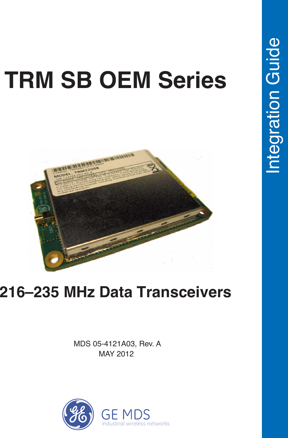
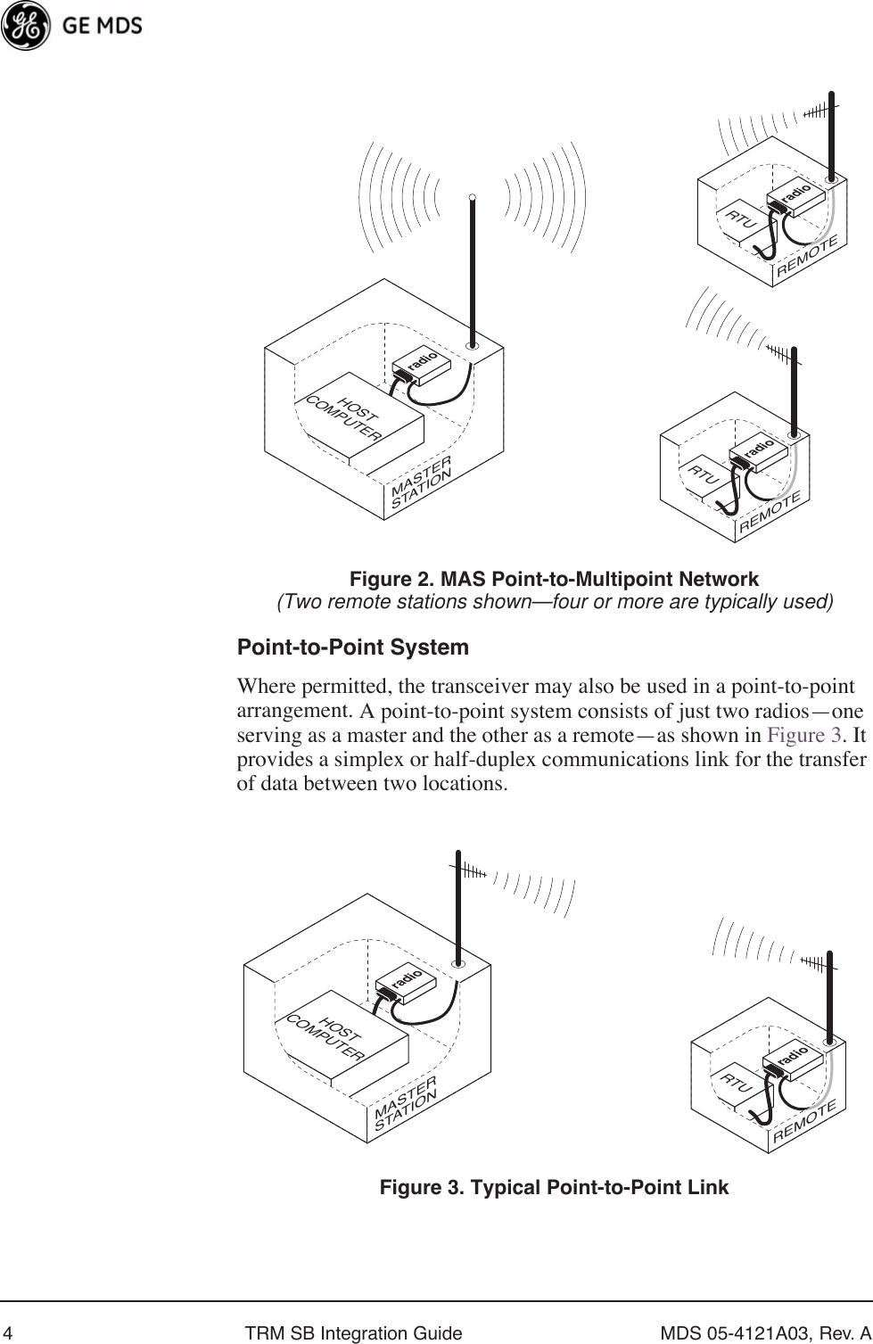
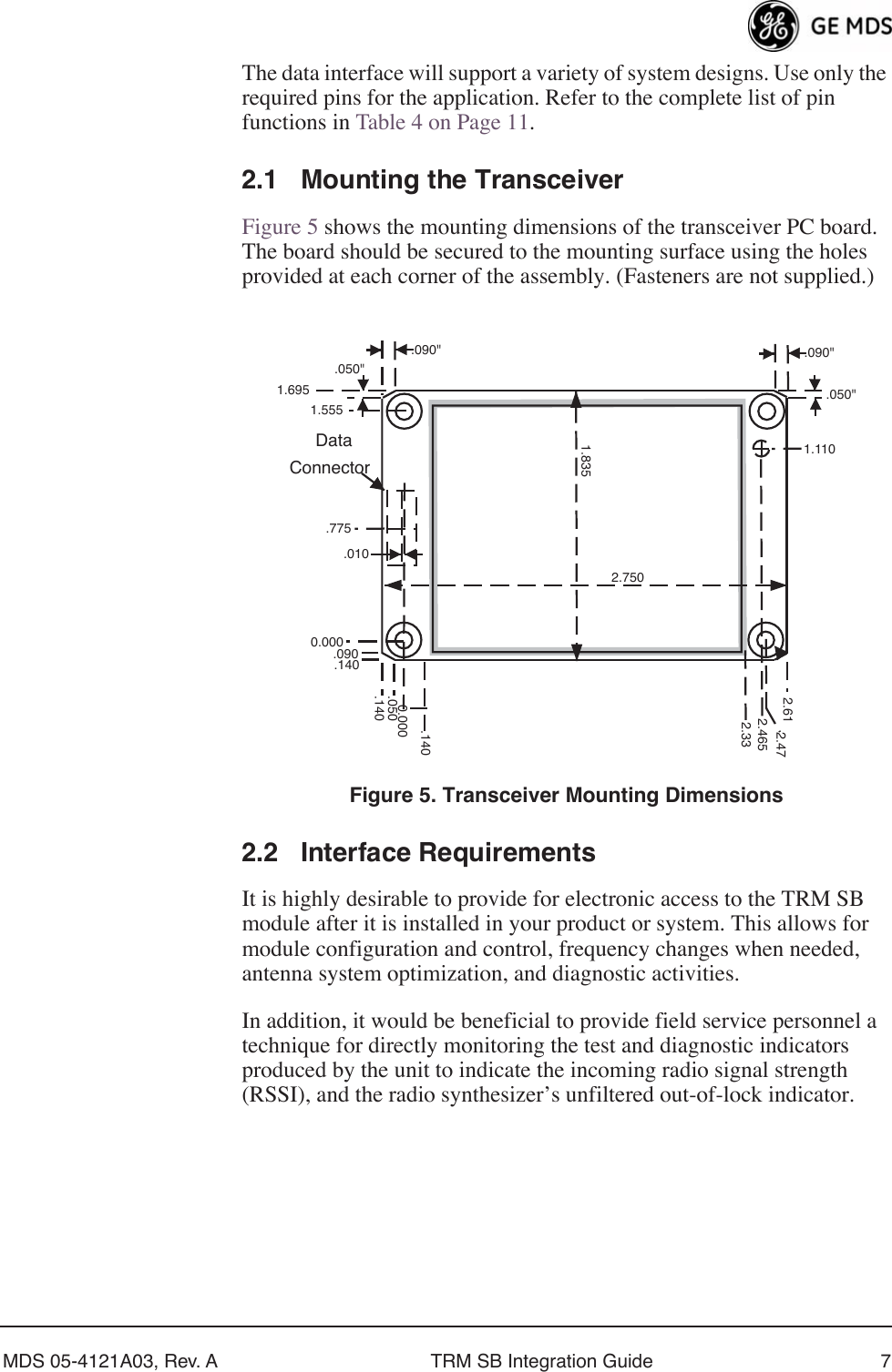
![14 TRM SB Integration Guide MDS 05-4121A03, Rev. ABT [.x] Relative TX Bandwidth• Valid options are .3 and .5• Leading zero (Ø) not permittedNOTE: Must complement BAUD and BW values. (See Table 1 on Page 2.)BW [xx.x] Channel Bandwidth• Options: 25 and 12.5 kHzNOTE: Must complement BT and BW values. (See Table 1 on Page 2.)CLK [xx] Clock Output PinSelects which serial clock line to use for transmit operation. • Options: TX and RX• TX = Pin 8/TXC• RX = Pin 6/RXCCDR [–xxx] Receiver Carrier Detect Threshold • Inhibits the receiver from processing an incoming signal unless it is above the setting’s level.• Range: –50 to –120 NOTE: A setting of -120 removes any limitation on signal detection.CDT [–xxx] Transmit Carrier Detect Threshold Inhibits the transmitter from operating in the presence of a strong on-channel signal until the signal level is below the setting level.• Range: –50 to –120 NOTES:• –50 will effectively allow transmissions anytime• –120 will effectively prohibit transmissions. • Minus sign (–) required for data entry PWR [x] RF Power Output LevelOptions: H = High PowerL = Low PowerSCRAM [xxx] Data Scrambler/Descrambler ON/OFF Options: ON or OFF SREV [xxx] Software Revision of installed firmwareSER Serial Number of the radioRSSI Received Signal Strength Indictor• Displays the current received RF signal level• One measurement per request by command• Reading is accurate to within 3 dB from –100 dBm to –60 dBmNOTE: A continuous RSSI signal available during receive state on the DATA INTERFACE connector (J100-Pin12).Table 5. Command Summary (Continued)Command Function](https://usermanual.wiki/GE-MDS/DS-TRM220SB/User-Guide-1721875-Page-20.png)
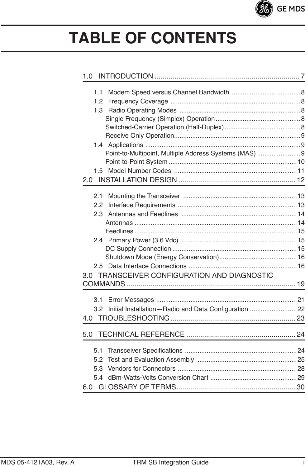
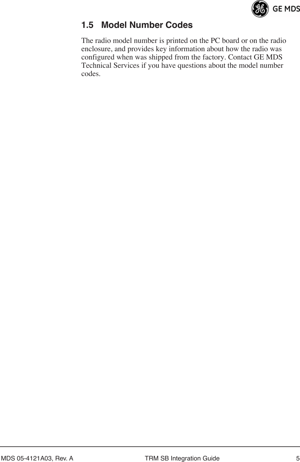
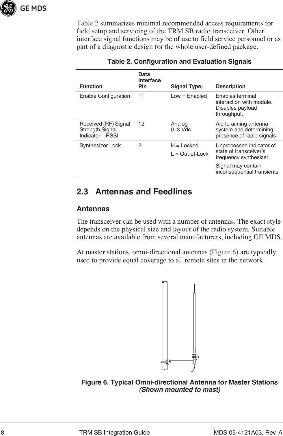
![MDS 05-4121A03, Rev. A TRM SB Integration Guide 153.1 Error MessagesListed below are some possible error messages that may be encountered when using the terminal interface:UNKNOWN COMMAND—The command was not recognized. Refer to the command description for command usage information.INCORRECT ENTRY—The command format or its associated values were not valid. Refer to the command description for command usage information.COMMAND FAILED—The command was unable to successfully complete. This may indicate an internal software problem.NOT PROGRAMMED—Software was unable to program the internal radio memory or the requested item was not programmed. This is a serious internal radio error. Contact MDS for assistance.TEXT TOO LONG—Response to OWN command when too many characters have been entered. Refer to the command description for command usage information.NOT AVAILABLE—The entered command or parameter was valid, but it referred to a currently unavailable choice. Refer to the command description for command usage information.OWN [xxx] Owner’s MessageDisplays an optional owner message• Enter OWN to display current entry.• Enter OWN followed by up to 30 characters to program.KEY Transmitter Carrier Key• Test command for technicians to key the radio with a modulated carrier.• Use DKEY command to cease transmissionNOTES: • Use only for test purposes.• No time-out timer on this function.DKEY Unkey Transmitter Test CarrierTable 5. Command Summary (Continued)Command Function](https://usermanual.wiki/GE-MDS/DS-TRM220SB/User-Guide-1721875-Page-21.png)