GE MDS DS9710-1 9710A Data Transceiver User Manual Exhibit 22 Installation and Operation Guide
GE MDS LLC 9710A Data Transceiver Exhibit 22 Installation and Operation Guide
GE MDS >
Contents
- 1. Exhibit 22 Installation and Operation Guide
- 2. Revised Manual 2
Exhibit 22 Installation and Operation Guide
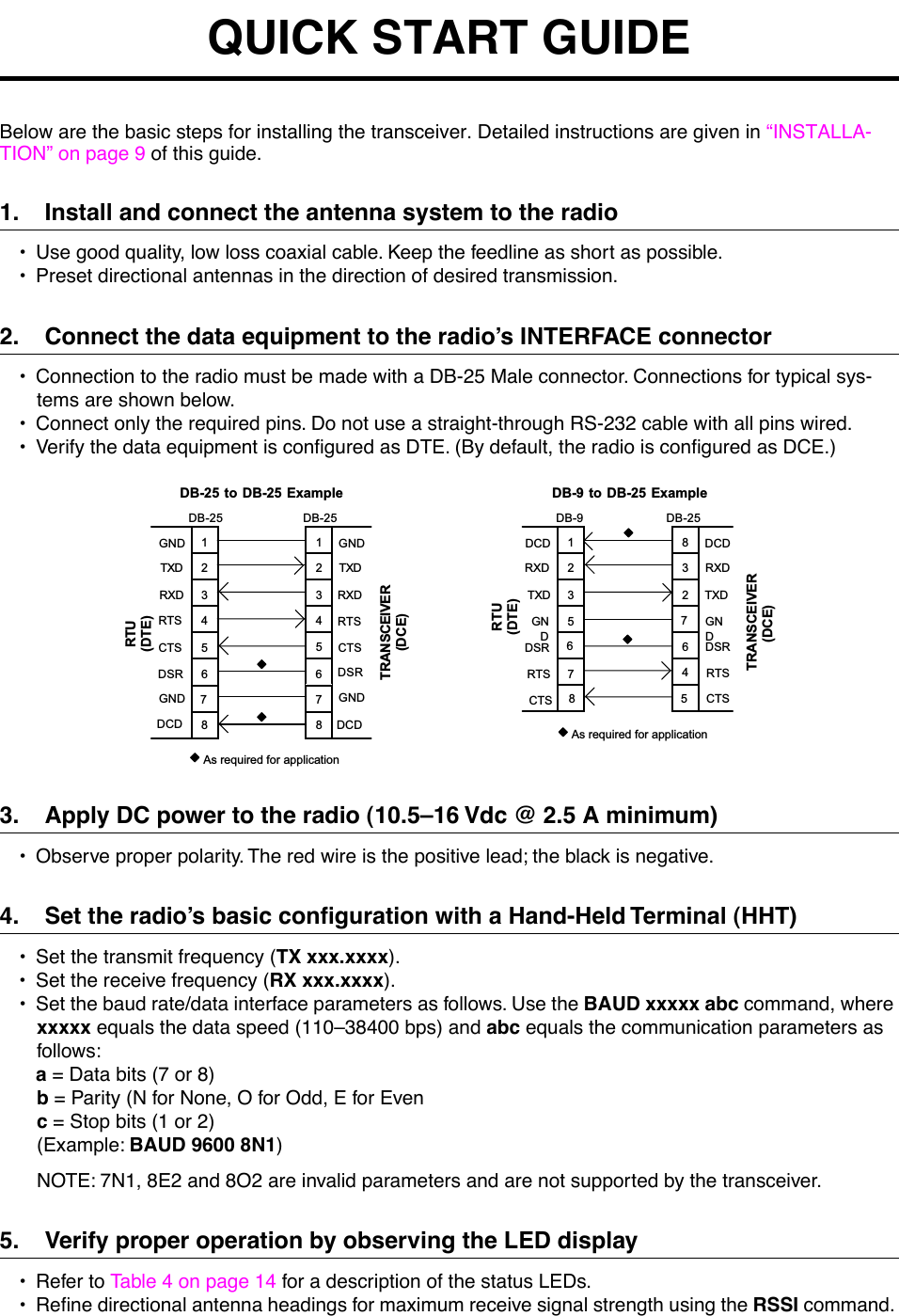
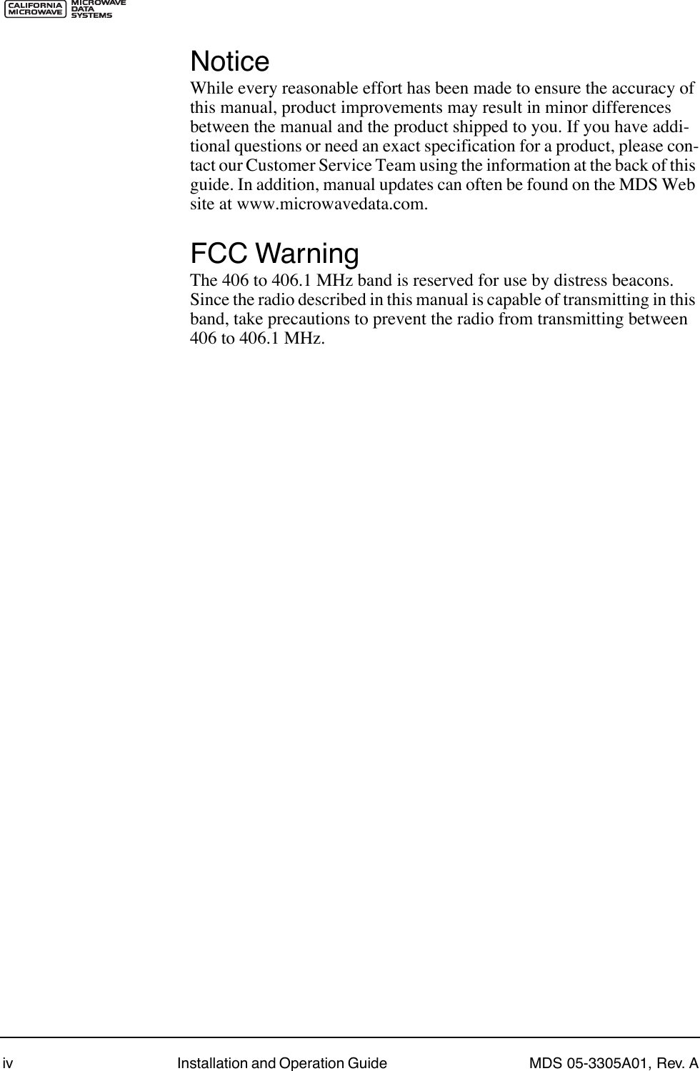
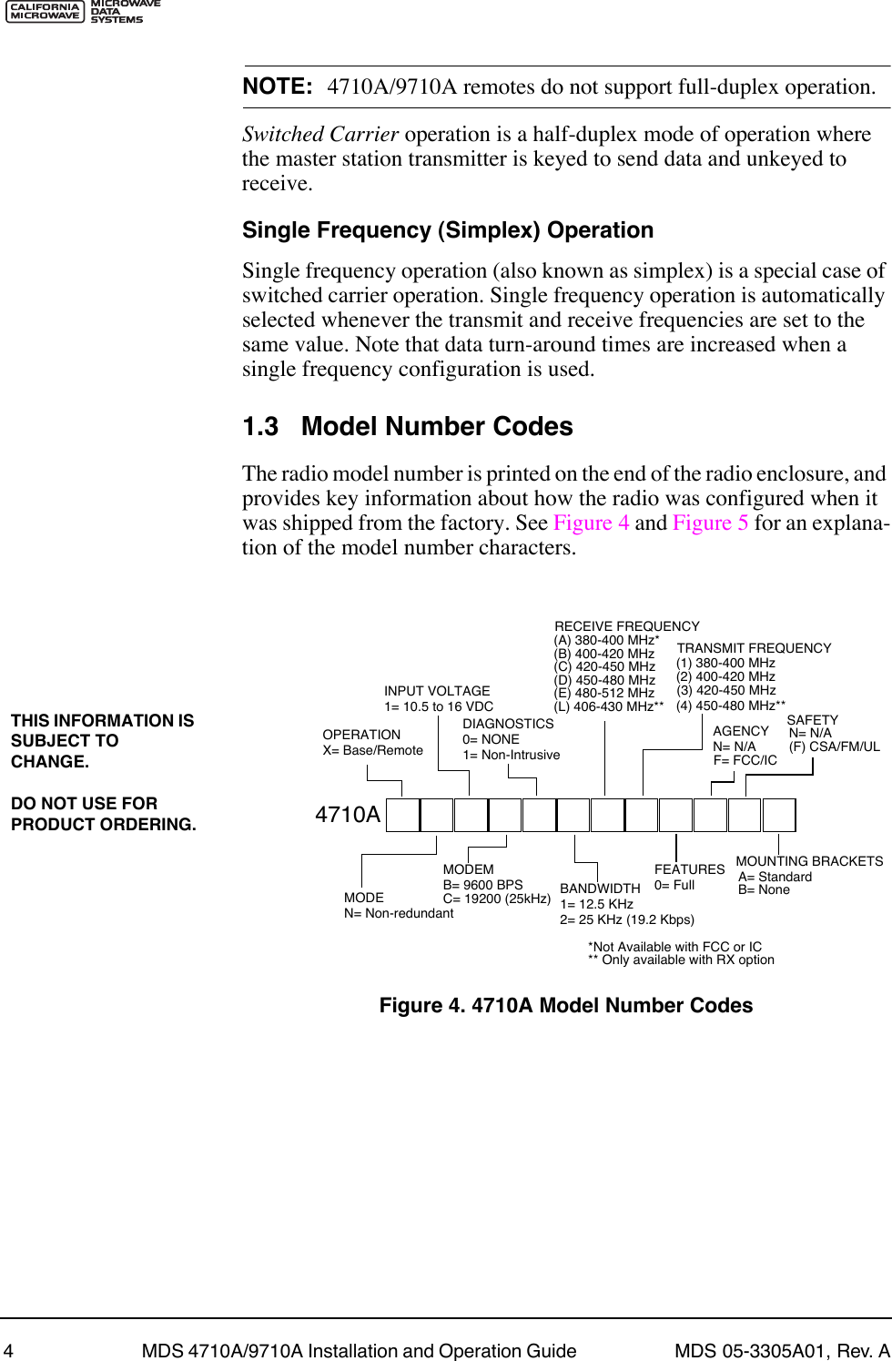
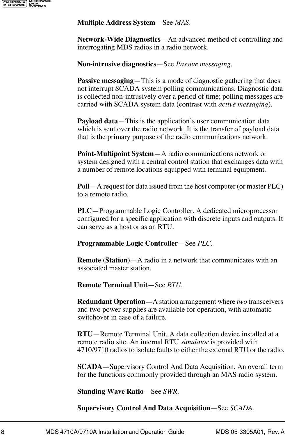
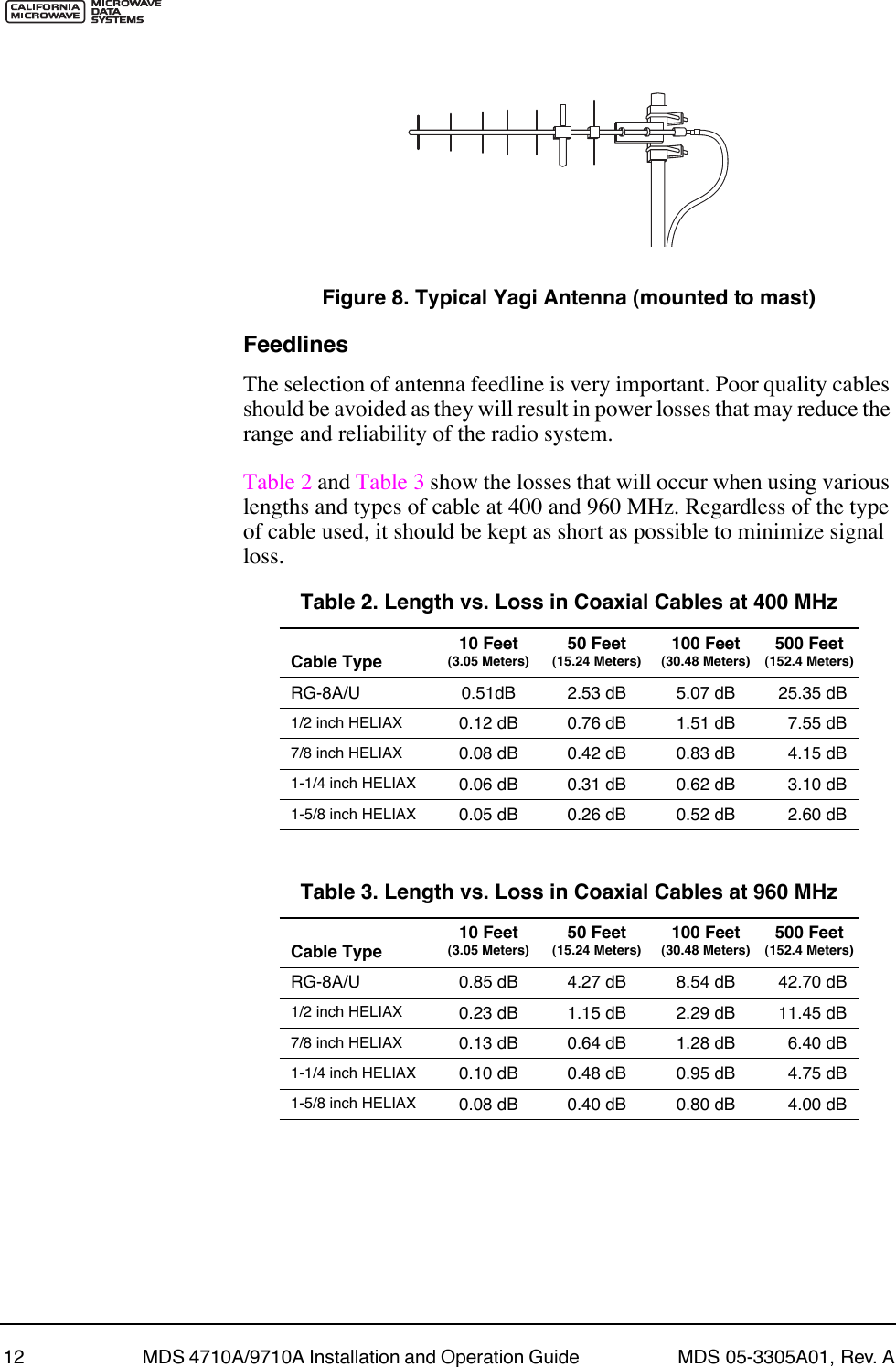
![MDS 05-3305A01, Rev. A MDS 4710A/9710A Installation and Operation Guide 19Invisible place holderFigure 11. HHT Setup Display2. The Þrst of 15 menu items is displayed. Settings are reviewed by pressing the NEXT function controlled by the key. Parameter set-tings are changed by pressing the ROLL function controlled by the key.3. Set up the HHT as listed in Table 6.5.3 Keyboard CommandsTable 7 is a reference chart of software commands for the transceiver. Programmable information is shown in brackets [ ] following the com-mand name. See Section 5.4, Detailed Command Descriptions (page 22) for detailed command descriptions.Entering CommandsTo enter a command, type the command, followed by an key-stroke. For programming commands, the command is followed by and the appropriate information or values, then .Table 6. HHT Operational Settings Parameter Setting Parameter SettingRe-init HT NO Scroll On 33rdBaud Rate 9600 Cursor ONComm bits 8,1,n CRLF for CR OFFParity Error OFF Self Test FASTKey Repeat OFF Key Beep ONEcho OFF Screen Size 80Shift Keys YES Menu Mode LONGCtl Chars PROCSFF1FFFEAENTERSPACE ENTER](https://usermanual.wiki/GE-MDS/DS9710-1.Exhibit-22-Installation-and-Operation-Guide/User-Guide-116062-Page-25.png)
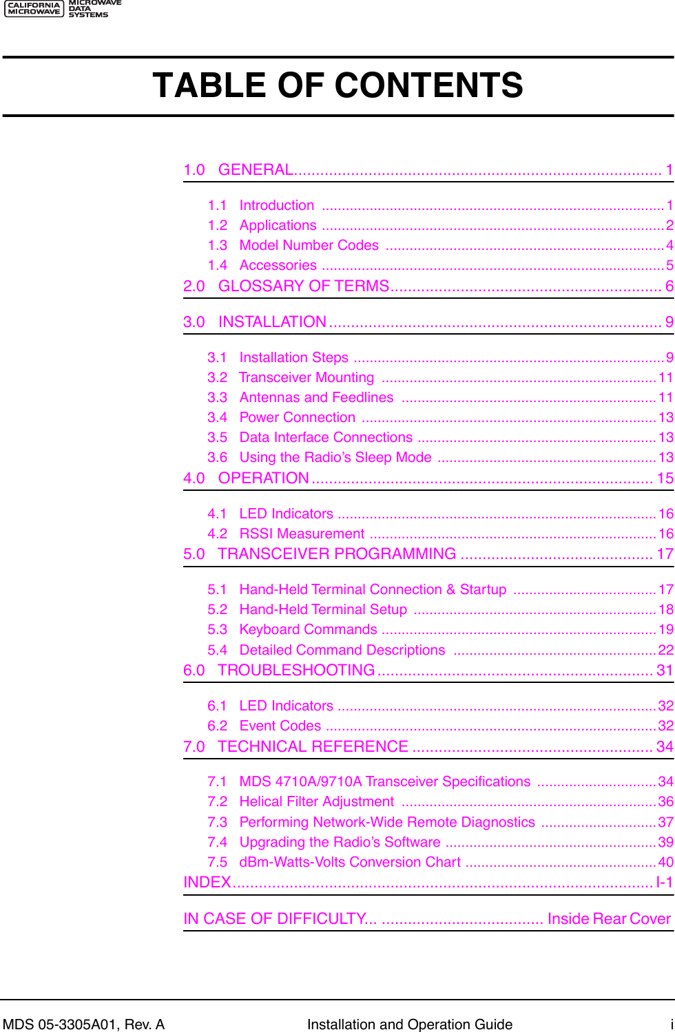
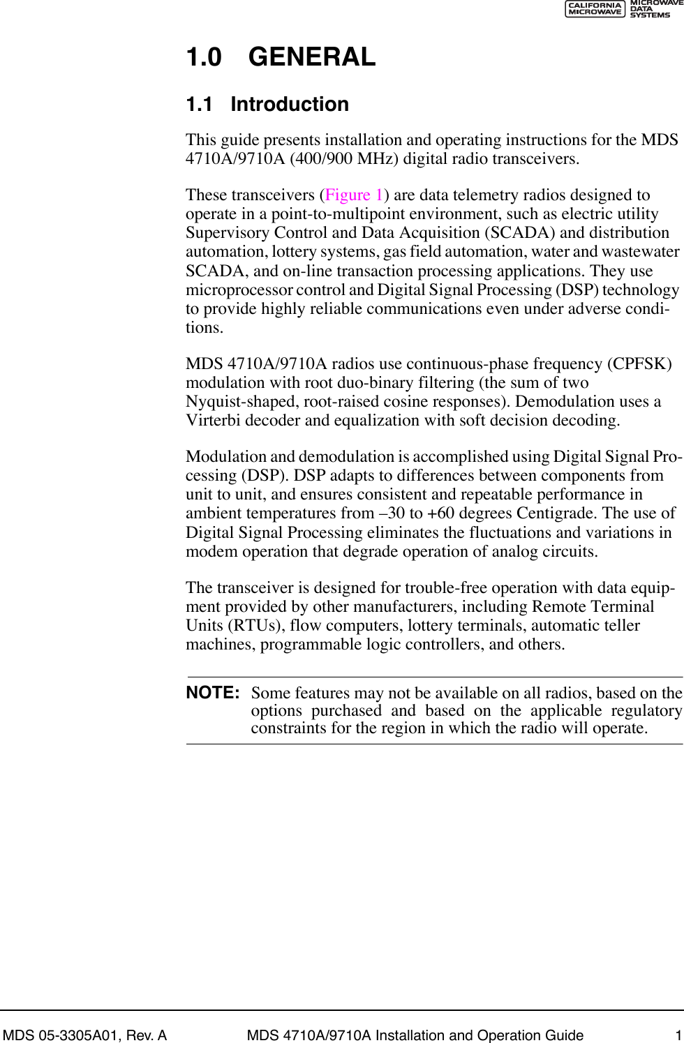
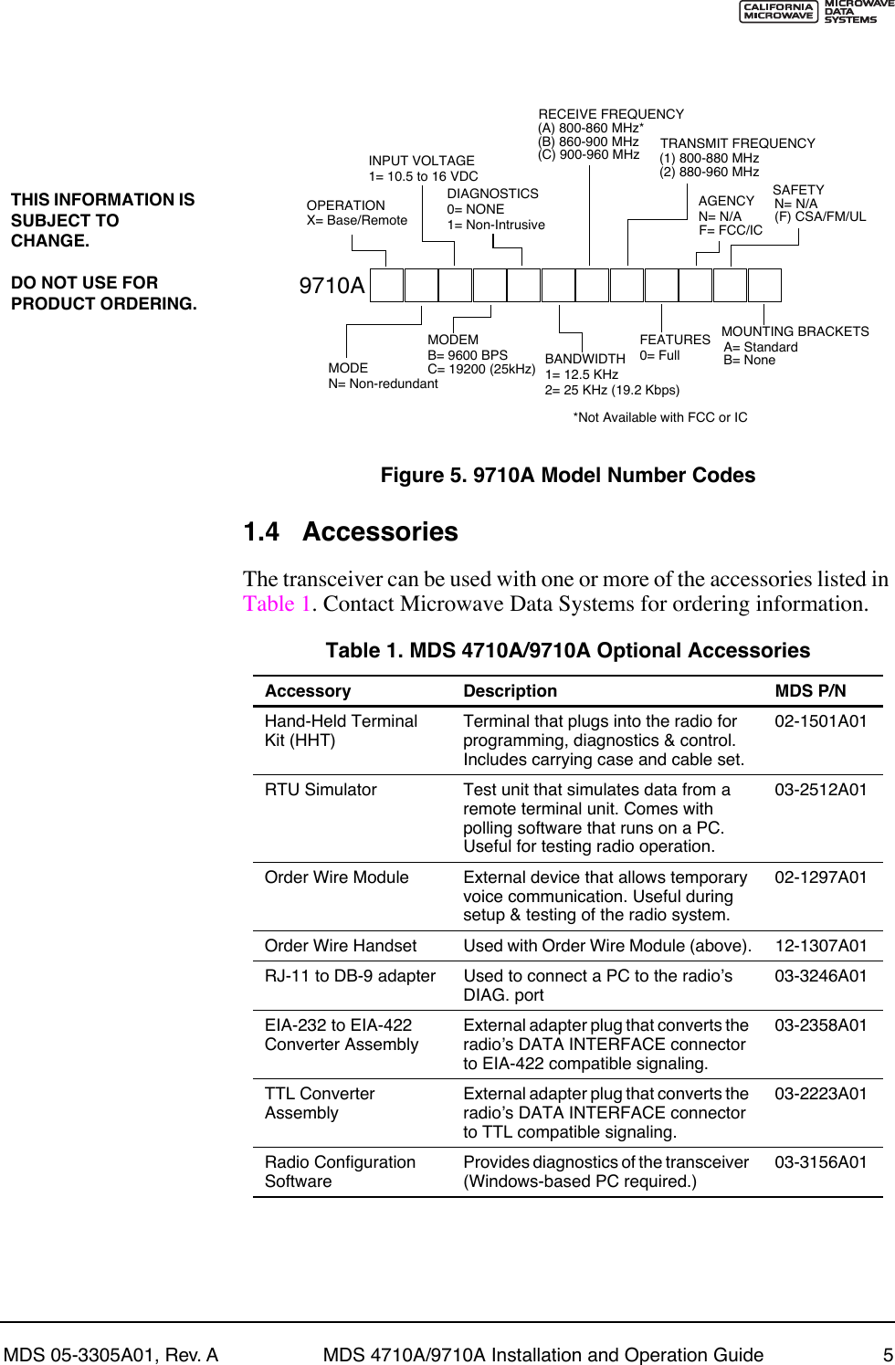
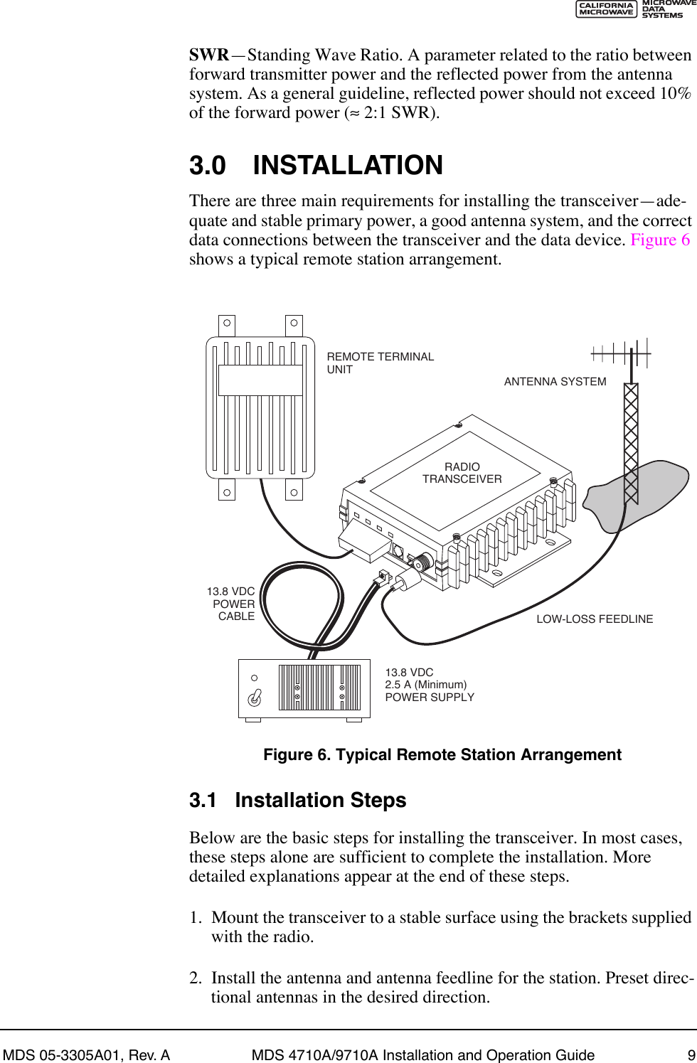
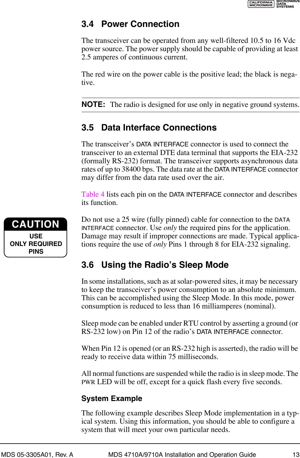
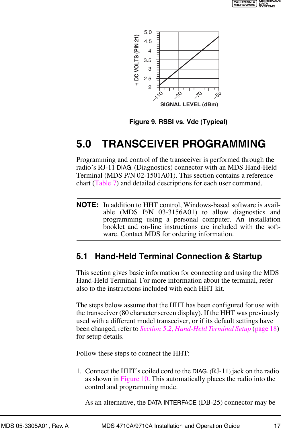
![MDS 05-3305A01, Rev. A MDS 4710A/9710A Installation and Operation Guide 21Table 7. Command summary Command name Function AMASK [0000 0000ÐFFFF FFFF] Details page 23Set or display hex code identifying which events trigger an alarm. ASENSE [HI/LO] Details page 24Set or display the state of the alarm output signal to ACTIVE HI or ACTIVE LO. BAUD [xxxxx abc] Details page 24Set or display the DATA INTERFACE data rate and control bits. BUFF [ON, OFF] Details page 24Enables or disables the internal radio data buffer. CTS [0Ð255] Details page 25Set or display the Clear-to-Send delay in seconds. CKEY [ONÐOFF] Details page 25Enables or disables the continuously keyed mode. Note: Remotes cannot receive when keyed. DATAKEY [ON, OFF] Details page 25Toggles between key-on-data and key-on-RTS. DKEY Details page 26 Dekey the radio (transmitter OFF). This is generally a radio test command. DLINK [ON/OFF/xxxx] Details page 26Configures local diagnostic link protocol. DMGAP [xx] Details page 26(diagnostics) Sets the amount of time to wait after the receipt of a character before interpreting the next received character as the start of a new message. DTYPE [NODE/ROOT] Details page 26(diagnostics) Sets up a radio as a root or node radio. DUMP Details page 26 Display all programmable settings. HREV Details page 26 Display the Hardware Revision level. INIT Details page 27 Set radio parameters to factory defaults. INIT [4710/9710] Details page 27Configure radio for use without P-20 chassis. Restores certain transceiver defaults before using the INIT x720 command. INIT [4720/9720] Details page 27Configure radio for use with P-20 chassis. KEY Details page 27 Key the radio (transmitter ON). This is generally a radio test command. MODEL Details page 27 Display the model number of the radio. MODEM [xxxx, NONE] Details page 28Set the modem characteristics of the radio. OWM [XXX...] Details page 28Set or display the ownerÕs message. OWN [XXX...] Details page 28Set or display the ownerÕs name. PTT [0Ð255] Details page 28Set or display the Push-to-Talk delay in milliseconds.](https://usermanual.wiki/GE-MDS/DS9710-1.Exhibit-22-Installation-and-Operation-Guide/User-Guide-116062-Page-27.png)
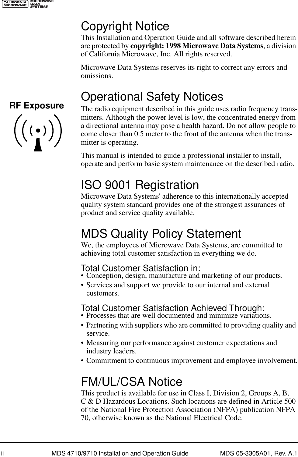
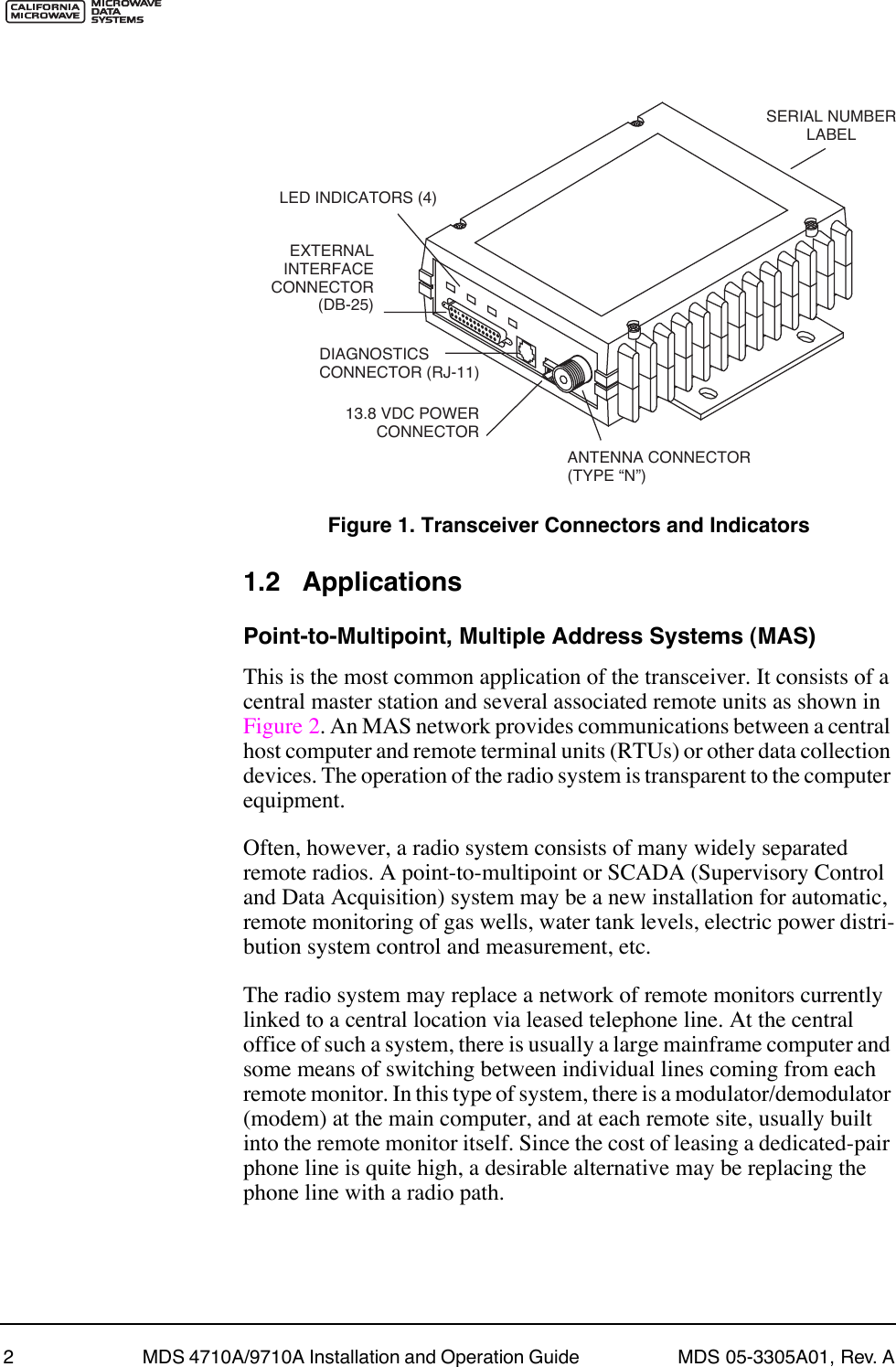
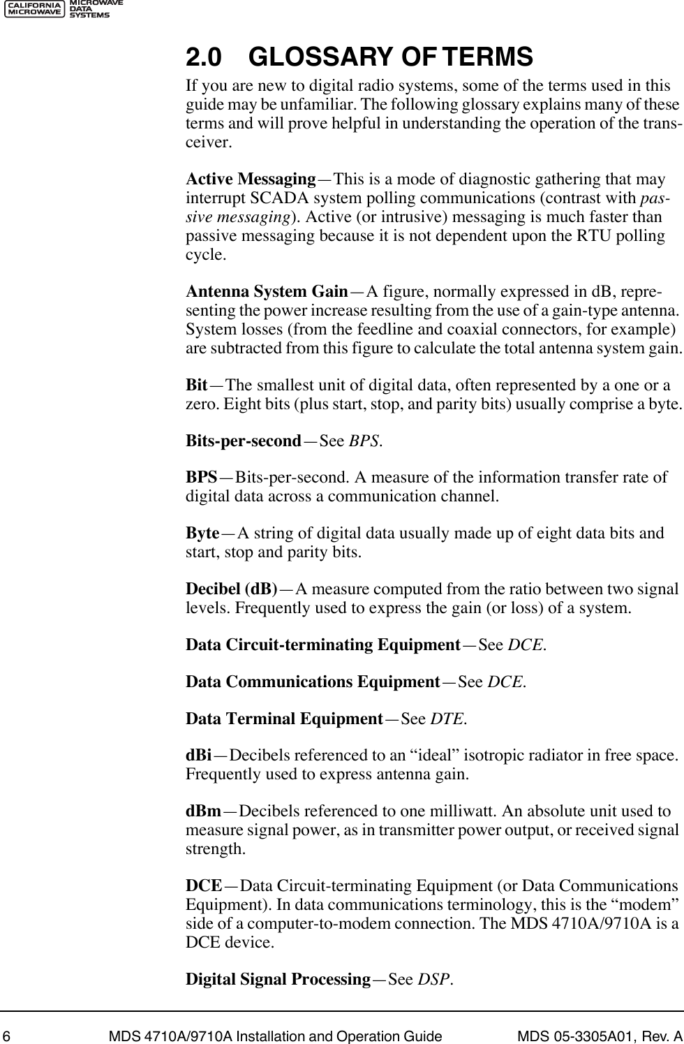
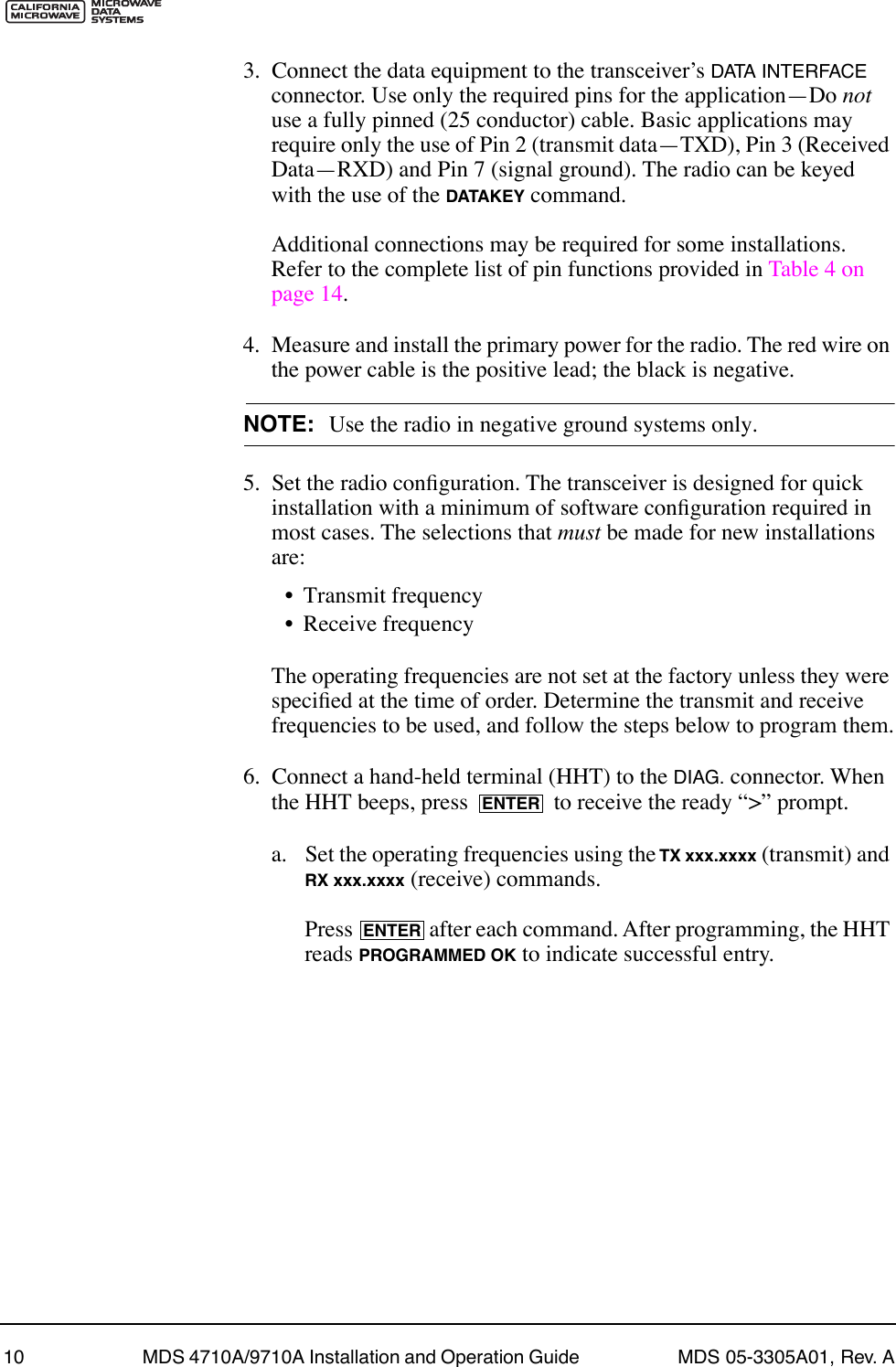
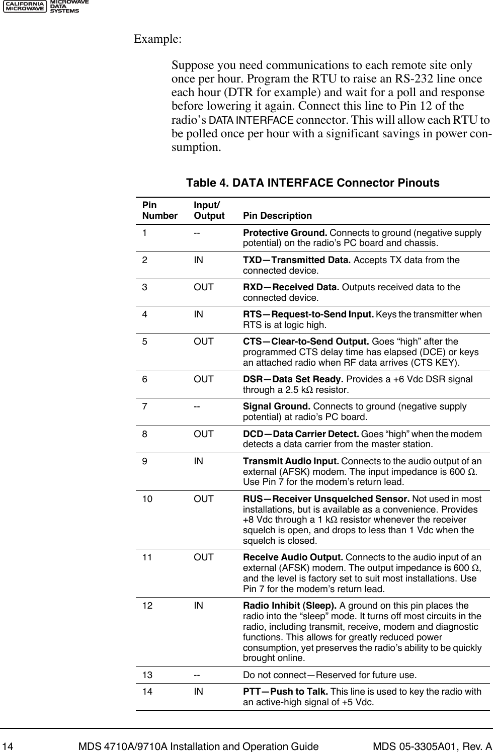
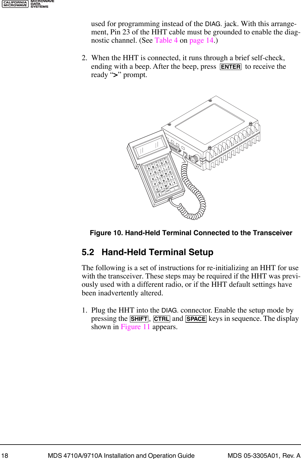
![22 MDS 4710A/9710A Installation and Operation Guide MDS 05-3305A01, Rev. A5.4 Detailed Command DescriptionsThe only critical commands for most applications are transmit and receive frequencies (RX xxx.xxxx, TX xxx.xxxx). However, proper use of the additional commands allows you to tailor the transceiver for a spe-cific use, or conduct basic diagnostics on the radio. This section gives more detailed information for the user commands previously listed in Table 7 (page 21).In many cases, the commands shown here can be used in two ways. First, you can type only the command name to view the currently pro-grammed data. Secondly, you can set or change the existing data by typing the command, followed by a space, and then the desired entry. In the list below, allowable programming variables, if any, are shown in brackets following the command name. PWR [20Ð37] Details page 28Set or display the transmit power setting. RSSI Details page 28 Display the Received Signal Strength Indication. RTU [ON/OFF/0-80] Details page 29Re-enables or disables the radioÕs internal RTU simulator and sets the RTU address. RX [xxx.xxxx] Details page 29Set or display receiver frequency. RXTOT [NONE, 1-255] Details page 29Set or display the value of the receive time-out timer. SCD [0-255] Details page 29Set or display the Soft-carrier Dekey delay in milliseconds. SER Details page 29 Display the radio serial number. SHOW [DC, PORT, PWR] Details page 30Display the DC voltages, diagnostics port, and transmit power level. SREV Details page 30 Display the Software Revision Level. STAT Details page 30 Display radio status and alarms. TEMP Details page 30 Display the internal temperature of the radio in degrees C. TOT [1-255, ON, OFF] Details page 31Set or display the Time-out Timer delay in milliseconds. TX [xxx.xxxx] Details page 31Set or display the transmit frequency. UNIT [10000...65000] Details page 31Set or display the transceiverÕs unit address.Table 7. Command summary (Continued)Command name Function](https://usermanual.wiki/GE-MDS/DS9710-1.Exhibit-22-Installation-and-Operation-Guide/User-Guide-116062-Page-28.png)
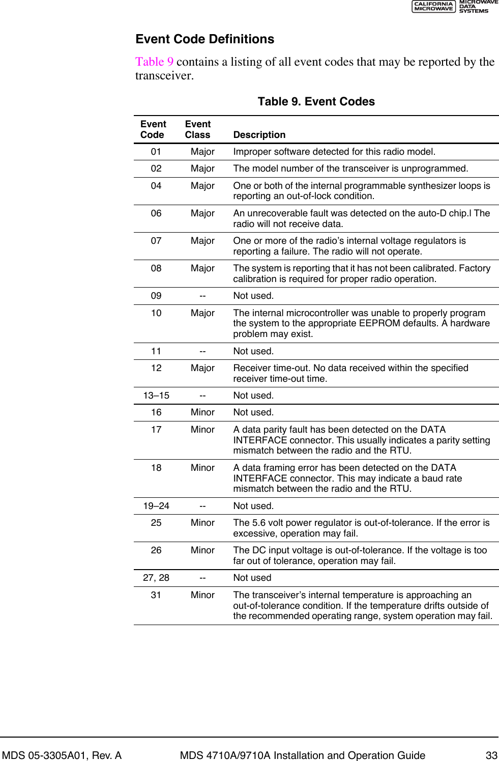
![MDS 05-3305A01, Rev. A MDS 4710A/9710A Installation and Operation Guide 23AMASK [0000 0000ÐFFFF FFFF]The AMASK command displays or sets which events cause the alarm output signal to be active. Normally, the mask is FFFF FFFF, meaning that any of the 32 possible events will activate the alarm output signal.Entering the AMASK command alone displays the current setting of alarm events in hexadecimal format.Entering the AMASK command followed by an eight-digit hexadecimal number reprograms the specified events to trigger an alarm.The eight-digit hexadecimal number used as the command parameter is used to classify up to 32 events as alarm triggers, or disable alarm noti-fication for an event. (See Table 8 below for a list of events.) The hex value for the mask corresponds to the hex value for the STAT command (page 30). Each bit that is a Ô1Õ identifies the associated alarm condition as a major alarm. Each bit that is a Ô0Õ disables major alarm notification for that condition. If both the major and minor alarm bits are set to Ô0Õ for that condition, alarm notification is entirely disabled. For more infor-mation on configuring the alarm response, contact Microwave Data Sys-tems and request Application Bulletin 98-002.Table 8. Text messages of alarm event codes Event Number Text Message01 Hardware mismatch02 Model number not programmed03 Authorization fault04 Synthesizer out-of-lock07 Voltage regulator fault detected08 Radio not calibrated09 DSP download fault10 EEPROM write failure11 Checksum fault12 Receiver time-out16 Unit address not programmed17 Data parity error18 Data framing error20 Configuration error25 6V regulator output not in valid range26 DC input power is not in valid range31 Internal Temperature not in valid range](https://usermanual.wiki/GE-MDS/DS9710-1.Exhibit-22-Installation-and-Operation-Guide/User-Guide-116062-Page-29.png)
![24 MDS 4710A/9710A Installation and Operation Guide MDS 05-3305A01, Rev. AASENSE [HI/LO]The ASENSE command sets or displays the sense of the alarm output at Pin 25 of the DATA INTERFACE connector.Entering the ASENSE command alone shows whether the alarm output is active high or low. Entering the ASENSE command followed by HI or LO resets the alarm output to active high or low.BAUD [xxxxx abc]This command sets (or displays) the communication attributes for the DATA INTERFACE port. It has no effect on the RJ-11 DIAG. port.The first parameter (xxxxx) is baud rate. Baud rate is specified in bits-per-second (bps) and must be one of the following speeds: 110, 300, 1200, 2400, 4800, 9600, 19200, or 38400.The second parameter of the BAUD command (abc) is a three-character block indicating how the data is encoded:a = Data bits (7 or 8)b = Parity (N for None, O for Odd, E for Even)c = Stop bits (1 or 2)The factory default setting is 19200 baud, 8 data bits, no parity, 1 stop bit (Example: 19200 8N1).NOTE: 7N1, 8O2, and 8E2 are invalid communication settings and arenot supported by the transceiver.BUFF [ON, OFF]This command sets or displays the received data handling mode of the radio. The command parameter is either ON or OFF. The default is ON. The setting of this parameter affects the timing of how received RF data is sent out the INTERFACE connector. Outgoing (transmitted) data is not affected by this setting.If data buffering is OFF, the radio operates with the lowest possible average latency. Data bytes are thus sent out the INTERFACE port as soon as an incoming RF data frame is disassembled. Average and typical latency will both be below 10 ms, but idle character gaps may be intro-duced into the outgoing data flow.If data buffering is ON, the radio operates in seamless mode. Data bytes will be sent over the air as quickly as possible, but the receiver buffers (stores) the data until enough bytes have arrived to cover worst-case gaps in transmission. This mode of operation is required for protocols such as MODBUSª that do not allow gaps in their data transmission.](https://usermanual.wiki/GE-MDS/DS9710-1.Exhibit-22-Installation-and-Operation-Guide/User-Guide-116062-Page-30.png)
![MDS 05-3305A01, Rev. A MDS 4710A/9710A Installation and Operation Guide 25Note that seamless mode (BUFF ON) is intended only for applications where the transmitterÕs baud rate is greater than or equal to the receiverÕs baud rate. Enforcement of this rule is left up to the user.CKEY [ONÐOFF]The CKEY command enables or disables the continuously-keyed func-tion of the radio. When CKEY is set to ON, the radio is continuously keyed.CTS [0Ð255]The CTS (clear-to-send) command selects or displays the timer value associated with the CTS line response. The command parameter ranges from 0 to 255 milliseconds.For DCE operation, the timer specifies how long to wait after the RTS line goes high, before the radio asserts CTS and the DTE can transmit the data. A CTS value of zero keys the radio and asserts the CTS line immediately after the RTS line goes high.For CTS Key operation (see DEVICE command), the timer specifies how long to wait after asserting the CTS, before sending data out the DATA INTERFACE port. A timer value of zero means that data will be sent out the data port without imposing a key-up delay. (Other delays may be present based on selected radio operating parameters.)DATAKEY [ON, OFF]The DATAKEY command enables or disables the ability of the radio to key the transmitter as data is received at the DATA INTERFACE connector. Asserting RTS keys the radio regardless of this command setting.If DATAKEY is set to ON, the radio will key when a full data-character is received at the transceiverÕs DATA INTERFACE connector. If DATAKEY is set to OFF, the radio needs to be keyed by asserting either the RTS or PTT signal or with the CKEY or KEY command.DEVICE [DCE, CTS KEY]The DEVICE command controls or displays the device behavior of the radio. The command parameter is either DCE or CTS KEY.The default selection is DCE. In this mode, CTS will go high following RTS, subject to the CTS programmable delay time. If the DATAKEY com-mand is set to ON, keying can be stimulated by the input of characters at the data port. Hardware flow control is implemented by signaling the CTS line if data arrives faster than it can be buffered and transmitted.](https://usermanual.wiki/GE-MDS/DS9710-1.Exhibit-22-Installation-and-Operation-Guide/User-Guide-116062-Page-31.png)
![26 MDS 4710A/9710A Installation and Operation Guide MDS 05-3305A01, Rev. AIf CTS KEY is selected, the radio is assumed to be controlling another radio. The RTS line is ignored and the CTS line is used as a keyline con-trol for the other radio. CTS is asserted immediately following the receipt of RF data, but data will not be sent out the DATA INTERFACE port until after the CTS programmable delay time has expired. (This gives the other radio time to key.)DKEYThis command deactivates the transmitter after it has been keyed with the KEY command.DLINK [ON/OFF/xxxx]This command is used to configure the local diagnostic link protocol used in network-wide diagnostics.Entering DLINK ON enables the diagnostic link. Entering DLINK OFF dis-ables the diagnostic link.To change the diagnostic link, enter DLINK followed by one of the fol-lowing baud rates: 1200, 2400, 4800, 9600, 19200 (default).DMGAP [xx]The DMGAP command sets the amount of time in milliseconds to wait after the receipt of a character before interpreting the next received char-acter as the start of a new message. When data port baud rates are slow, the gap between characters within a poll may be so long that the radio interprets the next character as the start of a new poll. When diagnostics is being performed using passive messaging (see Performing Net-work-Wide Remote Diagnostics on page 37), this command may be used to change this behavior.DTYPE [NODE/ROOT]This command establishes the local radio as a root radio or node radio for network-wide diagnostics. Entering DTYPE NODE configures the radio as a node radio. Entering DTYPE ROOT configures the radio as a root radio. Entering the DTYPE command alone displays the current setting. See ÒPerforming Network-Wide Remote DiagnosticsÓ on page 37.DUMPThis command displays all the programmed settings with this one com-mand. The HHT display is too small to list all the command settings at one time. Therefore, this command is most useful if the command is issued from a computer or full-screen terminal.HREVThis command displays the transceiverÕs hardware revision level.](https://usermanual.wiki/GE-MDS/DS9710-1.Exhibit-22-Installation-and-Operation-Guide/User-Guide-116062-Page-32.png)
![MDS 05-3305A01, Rev. A MDS 4710A/9710A Installation and Operation Guide 27INITThe INIT command is used to re-initialize the radioÕs operating parame-ters to the factory defaults. This may be helpful when trying to resolve configuration problems that may have resulted from the entry of one or more improper command settings. If you are unsure of which command setting may have caused the problem, this command allows you to get back to a known working state. The following changes to the radio are made when INIT is entered:¥CTS is set to 0¥DATAKEY is set to ON¥DEVICE is set to DCE¥PTT is set to 0¥SCD is set to 0¥TOT is set to 30 seconds and set to ON¥PWR is set to +37 dBm (5 watts)All other commands stay in the previously established setting.INIT [4710/9710]This command sets the transceiver for operation outside the P-20 chassis by setting the following parameters as shown:ASENSE ACTIVE HIAMASK FFFF FFFF (assert alarm output on all alarms)RXTOT NONE (receive time-out timer disabled)This command can be used prior to using the INIT x720 command to restore the standard transceiver defaultsINIT [4720/9720]This command sets the transceiver for operation inside the P-20 chassis by setting the following parameters as shown:ASENSE ACTIVE LOAMASK FFFF 0000 (trigger on major alarms)RXTOT 20 (20 minute time-out timer)KEYThis command activates the transmitter. See also the DKEY command.MODELThis command displays the radioÕs model number code.](https://usermanual.wiki/GE-MDS/DS9710-1.Exhibit-22-Installation-and-Operation-Guide/User-Guide-116062-Page-33.png)
![28 MDS 4710A/9710A Installation and Operation Guide MDS 05-3305A01, Rev. AMODEM [xxxx, NONE]This command selects the radioÕs modem characteristics. Enter 9600 for digital operation, or enter NONE to select analog operation.OWM [XXX...]This is a command to display or program an ownerÕs message. To pro-gram the ownerÕs message, type OWM then the message, followed by .To display the ownerÕs message, type OWM then . The ownerÕs message appears on the display.OWN [XXX...]This is a command to display or program an ownerÕs name. To program the ownerÕs name, type OWN then the name, followed by .To display the ownerÕs name, type OWN then . The ownerÕs name appears on the display.PTT [0Ð255]This command sets or displays the key-up delay in milliseconds.This timer specifies how long to wait after the radio receives a key signal from either the PTT or RTS lines (on the DATA INTERFACE), before actu-ally keying the radio.PWR [20Ð37]NOTE: This function may not be available, depending on certificationrequirements in a particular country.This command displays or sets the desired RF forward output power set-ting of the radio. The PWR command parameter is specified in dBm and can range from 20 through 37. The default setting is 37 dBm (5 watts). To read the actual (measured) power output of the radio, use the SHOW PWR command. A dBm-to-watts conversion chart is provided in Section 7.5 (page 40).RSSIThis command continuously displays the radioÕs Received Signal Strength Indication (RSSI) in dBm units, until you press the Enter key. Incoming signal strengths from Ð50 dBm to Ð120 dBm can be read.ENTERENTERENTERENTER](https://usermanual.wiki/GE-MDS/DS9710-1.Exhibit-22-Installation-and-Operation-Guide/User-Guide-116062-Page-34.png)
![MDS 05-3305A01, Rev. A MDS 4710A/9710A Installation and Operation Guide 29RTU [ON/OFF/0-80]This command re-enables or disables the radioÕs internal RTU simu-lator, which runs with MDSÕ proprietary polling programs (poll.exe and rsim.exe). The internal RTU simulator is available whenever a radio has diagnostics enabled. This command also sets the RTU address that the radio will respond to.The internal RTU can be used for testing system payload data or pseudo bit error rate testing. It can be helpful in isolating a problem to either the external RTU or the radio.RX [xxx.xxxx]This command selects or displays the radioÕs receive frequency in MHz. The frequency step size is 6.25 kHz.If the customer frequency has not been programmed at the factory, a default frequency will be programmed in the radio near the center of the frequency band.NOTE: A large change in receive frequency (more than 5 MHz)requires adjustment of the receiver helical filters for maximumperformance and RSSI. See Section 7.2, Helical Filter Adjust-ment (page 36) for details.RXTOT [NONE, 1-255]The RXTOT command selects or displays the receive time-out timer value in minutes. This timer triggers an alarm (event 12) if data is not detected within the specified time.Entering the RXTOT command without a parameter displays the timer value in minutes. Entering the RXTOT command with a parameter ranging from 0 to 255 resets the timer in minutes. Entering the RXTOT command with the parameter NONE disables the timer.SCD [0-255]This command displays or changes the soft-carrier dekey delay in milli-seconds.This timer specifies how long to wait after the removal of the keying signal before actually releasing the transmitter. A value of 0 millisec-onds will unkey the transmitter immediately after the removal of the keying signal.SERThis command displays the radioÕs serial number as recorded at the fac-tory.](https://usermanual.wiki/GE-MDS/DS9710-1.Exhibit-22-Installation-and-Operation-Guide/User-Guide-116062-Page-35.png)
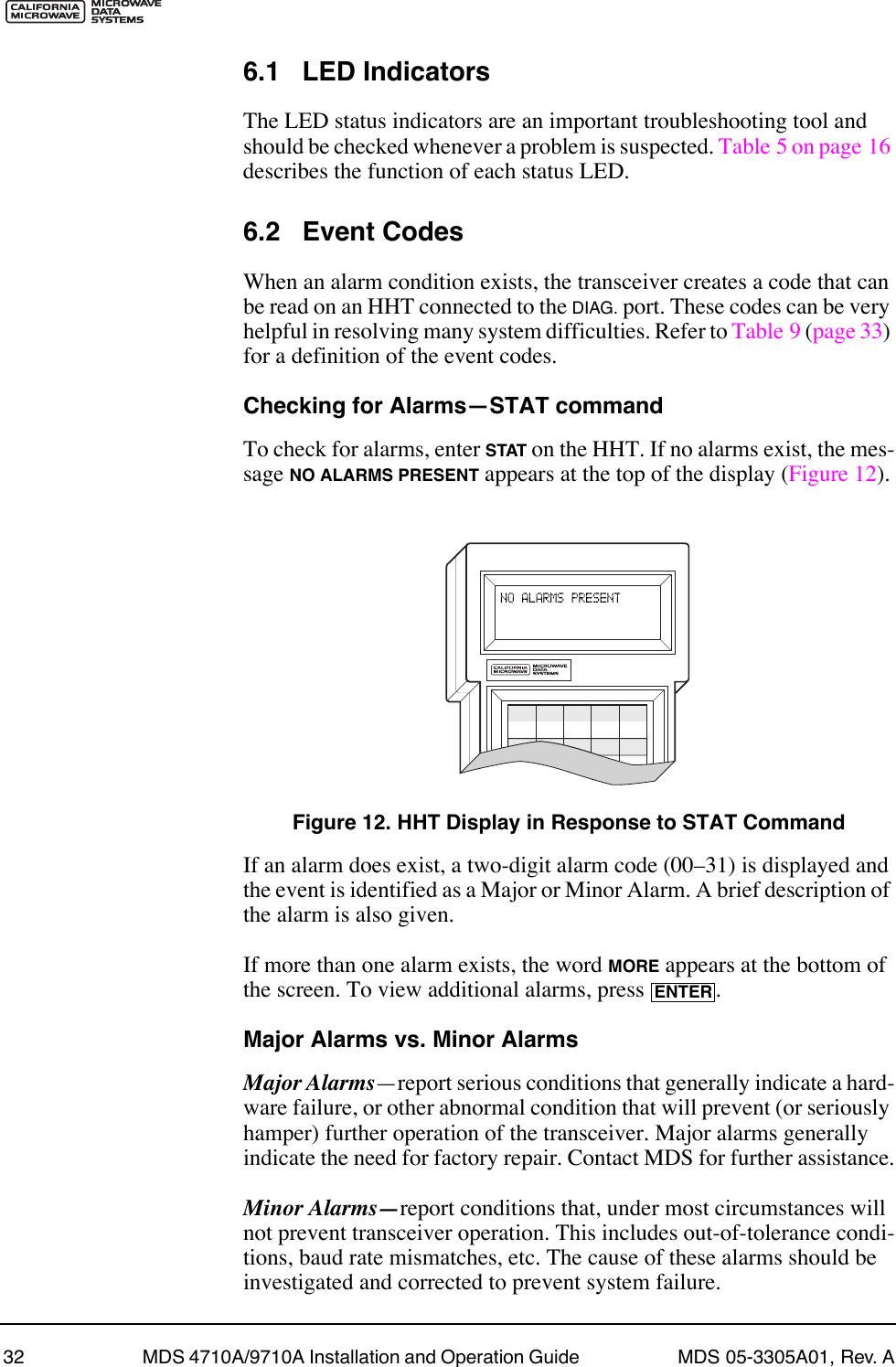
![30 MDS 4710A/9710A Installation and Operation Guide MDS 05-3305A01, Rev. ASHOW [DC, PORT, PWR]The SHOW command displays different types of information based on the command variables. The different parameters are:¥DCÑDisplay DC input/output voltages¥PORTÑDisplay the connector port (RJ-11 or DB-25) that is active for diagnostics and control.¥PWRÑDisplay RF power outputSNRThis command continuously displays the signal-to-noise ratio of the received signal expressed in dB, until you press the Enter key. As used in this guide, the signal-to-noise measurement is based upon the signal level following equalization, for received frames.The SNR is an indication of the received signal quality. The SNR indi-cation ranges from 10 dB to 33 dB. A value of 10 dB represents a very poor signal. A value of 24 dB represents a very good signal.When the SNR command is used, it causes the DIAG. port to enter an update mode, and the signal-to-noise ratio is updated and redisplayed every 2 seconds. The SNR continuously updates until the key is pressed.SREVThis command displays the software revision level of the transceiver firmware.STATThis command displays the current alarm status of the transceiver.If no alarms exist, the message NO ALARMS PRESENT appears at the top of the HHT display.If an alarm does exist, a two-digit code (00Ð31) is displayed and the alarm is identified as ÒMajorÓ or ÒMinor.Ó A brief description of the alarm code is also given.If more than one alarm exists, the word MORE appears at the bottom of the screen and additional alarms are viewed by pressing the key. Detailed descriptions of event codes are provided in Table 9 on page 33.TEMPThis command displays the internal temperature of the transceiver in degrees Celsius.ENTERENTER](https://usermanual.wiki/GE-MDS/DS9710-1.Exhibit-22-Installation-and-Operation-Guide/User-Guide-116062-Page-36.png)
![MDS 05-3305A01, Rev. A MDS 4710A/9710A Installation and Operation Guide 31TOT [1-255, ON, OFF]This command sets or displays the transmitter Time-out Timer value (1Ð255 seconds), as well as the timer status (ON or OFF). If the timer is on, and the radio remains keyed for a longer duration than the TOT value, the transmitter is automatically unkeyed.When this happens, the radio must be commanded back to an unkeyed state before a new keying command is accepted. The default timer value is 30 seconds.TX [xxx.xxxx]This command selects or displays the radioÕs transmit frequency in MHz. The frequency step size is 6.25 kHz.If the customer frequency has not been programmed at the factory, a default frequency will be programmed in the radio near the center of the frequency band.UNIT [10000...65000]The unit address is factory programmed to the last five digits of the serial number. 6.0 TROUBLESHOOTINGSuccessful troubleshooting of the radio system is not difficult, but it requires a logical approach. It is best to begin troubleshooting at the master station, as the rest of the system depends on the master for polling commands. If the master station has problems, the operation of the entire network can be compromised.It is good practice to start by checking the simple things. For proper operation, all radios in the network must meet these basic requirements:¥ Adequate and stable primary power. The radio contains an inter-nal self-resetting fuse (4A). Remove primary power to reset.¥ Secure connections (RF, data and power)¥ An efficient and properly aligned antenna system with a good received signal strength of at least Ð90 dBm. (It is possible for a system to operate with weaker signals, but reliability will be degraded.) ¥ Proper programming of the transceiverÕs operating parameters (see Section 5.0, TRANSCEIVER PROGRAMMING on page 17).¥ The correct interface between the transceiver and the connected data equipment (correct cable wiring, proper data format, timing, etc.)](https://usermanual.wiki/GE-MDS/DS9710-1.Exhibit-22-Installation-and-Operation-Guide/User-Guide-116062-Page-37.png)
![MDS 05-3305A01, Rev. A MDS 4710A/9710A Installation and Operation Guide 35TRANSMITTERFrequency Range 4710A* 9710A**One of these bands: 380Ð400 MHz 800Ð880 MHz400Ð450 MHz 880Ð960 MHz450Ð512 MHz406Ð530 MHz*Refer to Figure 4 on page 4 to determine which band the radio operates on.**Refer to Figure 5 on page 5 to determine which band the radio operates on.Modulation Type: Binary CPFSKCarrier Power: 0.1 watts to 5 wattsDuty Cycle: ContinuousOutput Impedance: 50 ohmsFrequency Stability: ±1.5 ppmChannel Spacing: 12.5 kHzAdjacent Channel Power: Ð60 dBcTransmitter SpuriousConducted EmissionsOperational: Ð36 dBm [73 dBc], 9 kHz to 1 GHzÐ30 dBm [67 dBc], 1 GHz to 12.5 GHzStandby: Ð57 dBm, 9 kHz to 1 GHzÐ47 dBm, 1 GHz to 12.5 GHzTransmitter SpuriousRadiated Emissions: Ð36 dBm [73 dBc], 9 kHz to 1 GHzÐ30 dBm [67 dBc], 1 GHz to 12.5 GHzHarmonics:2nd harmonic: Ð73 dBc3rd harmonic & higher: Ð67 dBcPower: 50 dBcTime-out Timer: 30 seconds, default (selectable with TOT)Transmitter Keying: Data activated or RTSRECEIVERFrequency Range4710A* 9710A**One of these bands: 380Ð400 MHz 800Ð860 MHz400Ð420 MHz 860Ð900 MHz420Ð450 MHz 900Ð960 MHz450Ð480 MHz480Ð512 MHz406Ð430 MHz*Refer to Figure 4 on page 4 to determine which band the radio operates on.**Refer to Figure 5 on page 5 to determine which band the radio operates on.Type: Double conversion superheterodyneFrequency Stability: 1.5 kHzMaximum Usable Sensitivity: Ð113 dBm BER at 10Ð2 (normal1)Ð107dBm BER at 10Ð2 (extreme2)1. Normal refers to:Temperature, +15 to +35 degrees CHumidity, 20% to 75%Voltages, Nominal Specified](https://usermanual.wiki/GE-MDS/DS9710-1.Exhibit-22-Installation-and-Operation-Guide/User-Guide-116062-Page-41.png)
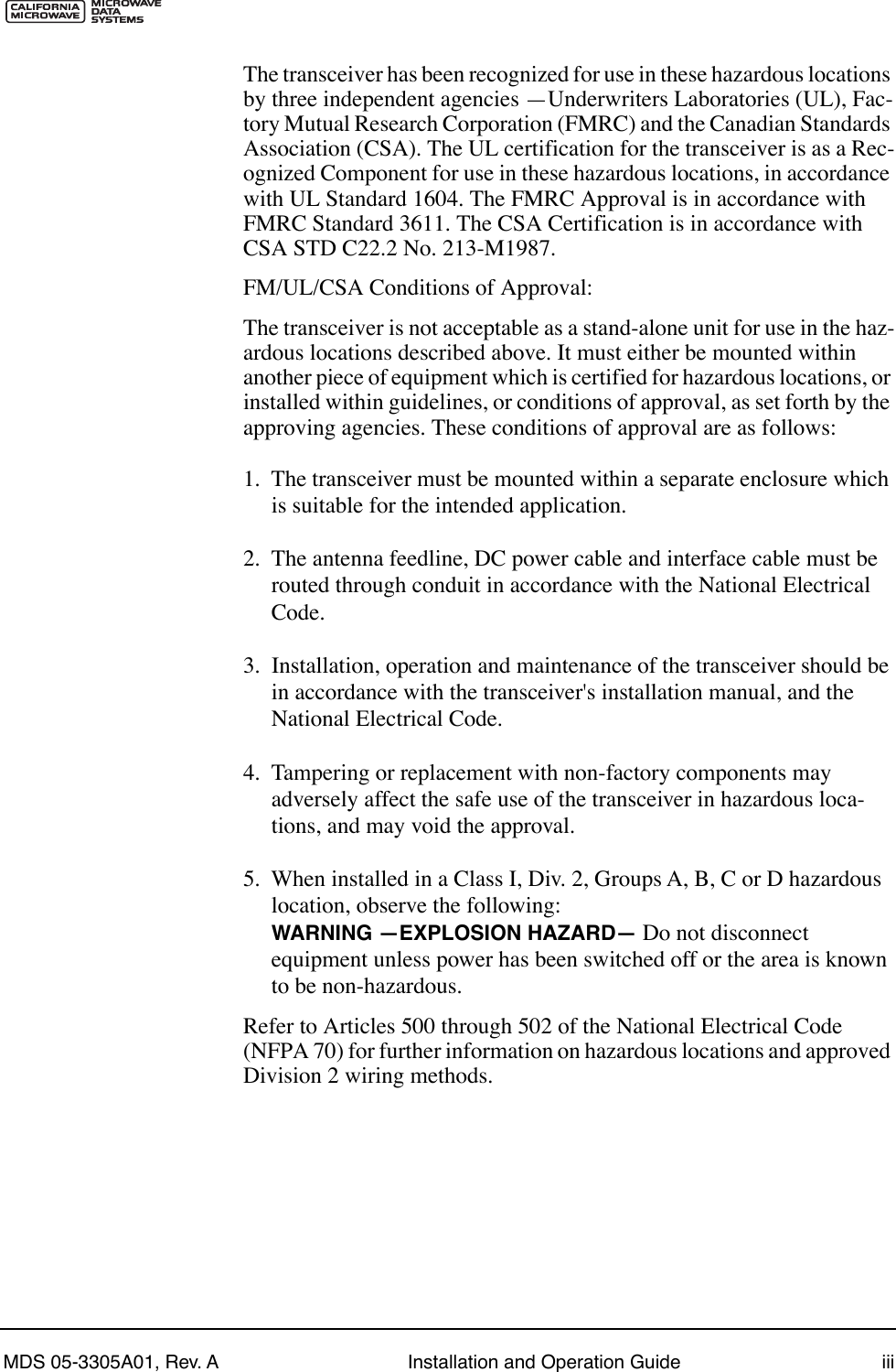
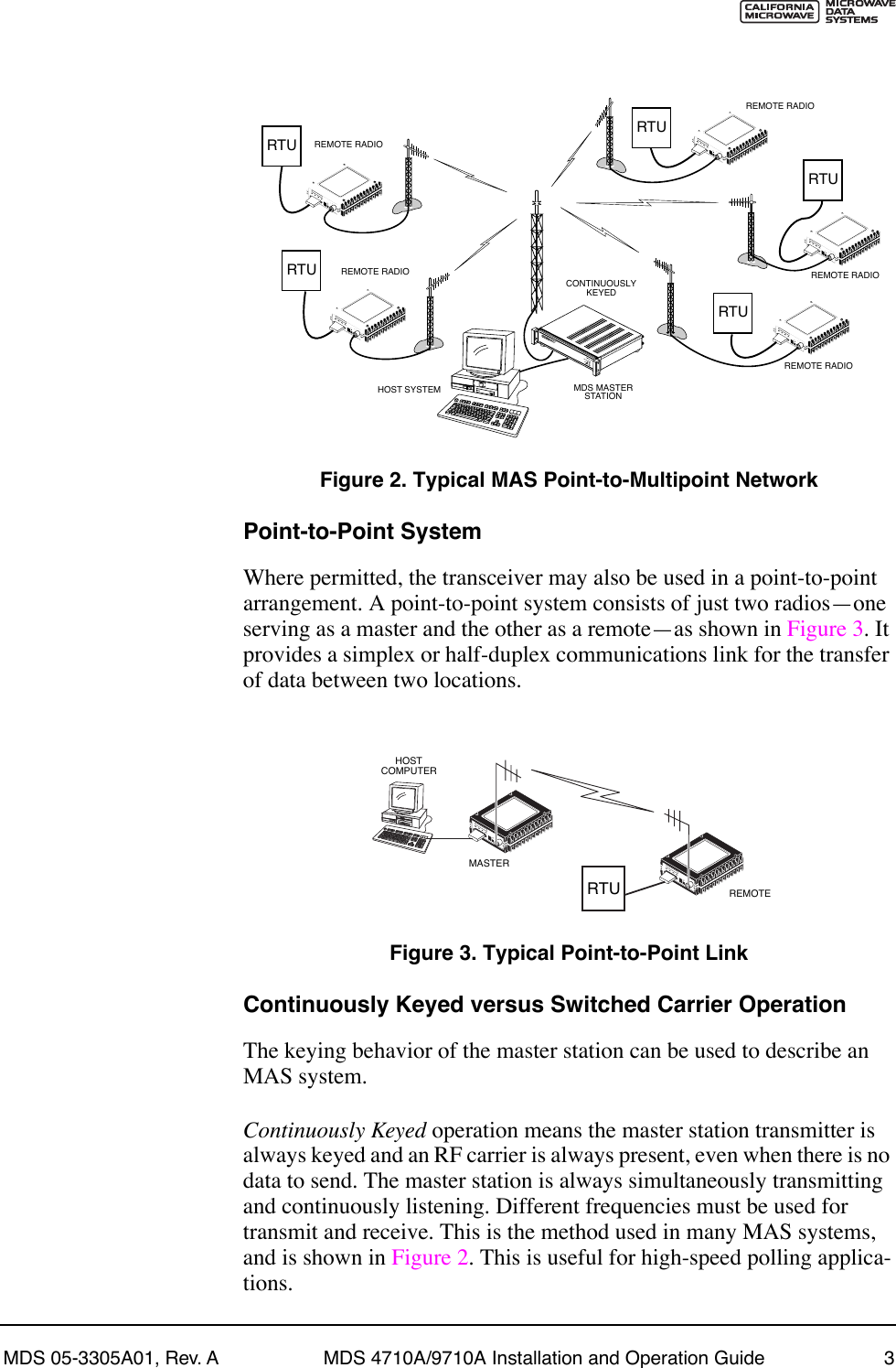
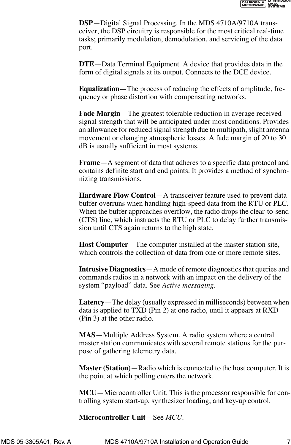
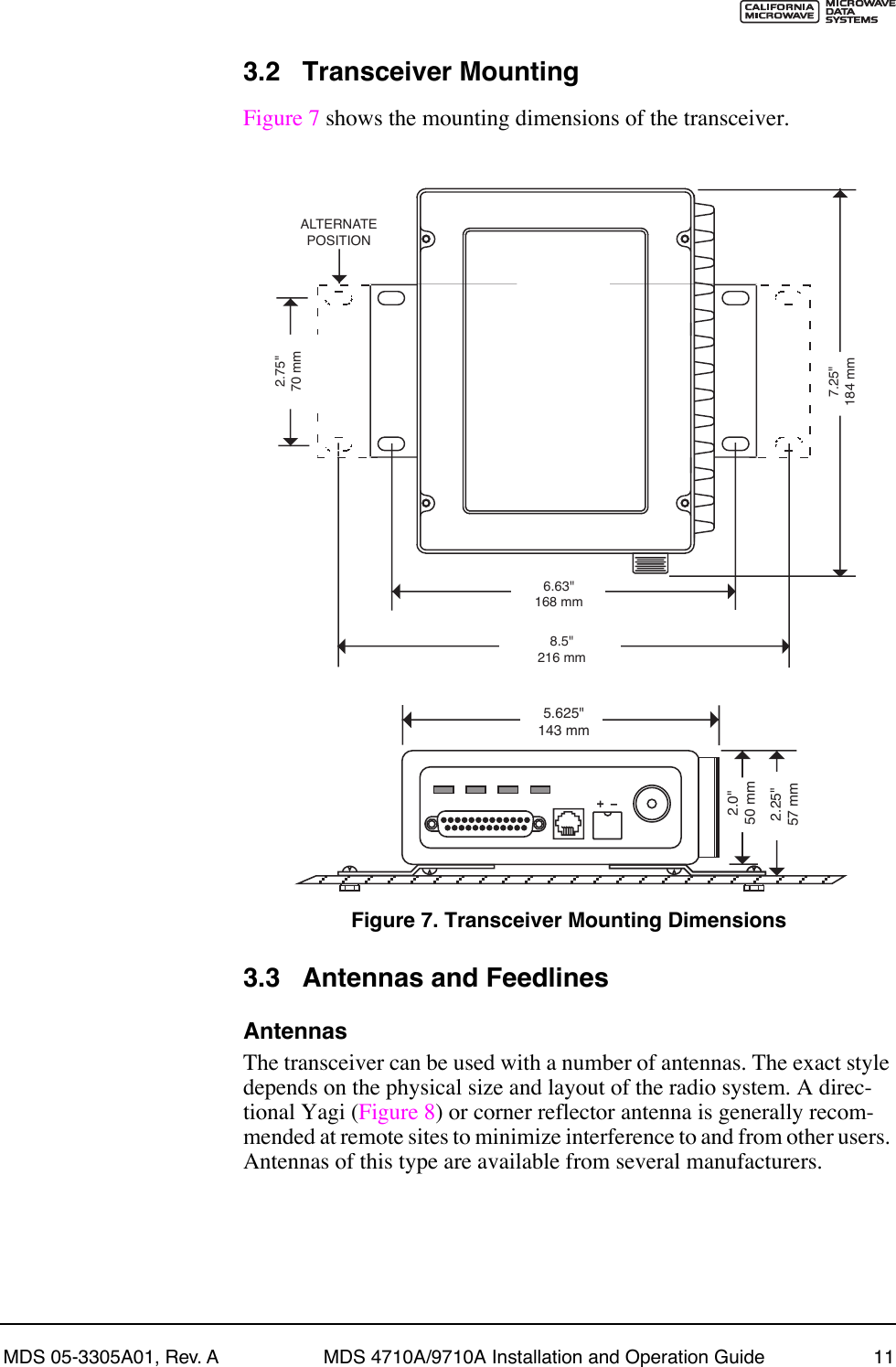
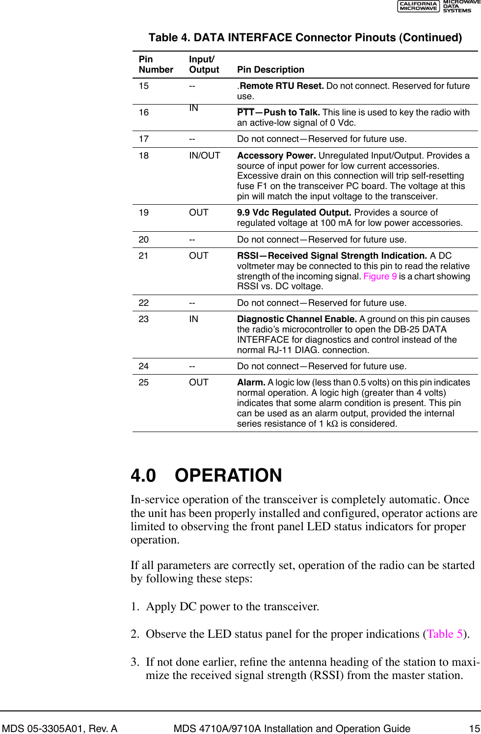
![38 MDS 4710A/9710A Installation and Operation Guide MDS 05-3305A01, Rev. AInvisible place holderFigure 14. Network-Wide Remote Diagnostics SetupIf a PC is connected to any radio in the network, intrusive polling (polling which briefly interrupts payload data transmission) can be per-formed. To perform diagnostics without interrupting payload data trans-mission, connect the PC to a radio defined as the ÒrootÓ radio. A radio is defined as a root radio using the DTYPE ROOT command locally, at the radio.A complete explanation of remote diagnostics can be found in MDSÕ Network-Wide Diagnostics System Handbook. See the Handbook for more information about the basic diagnostic procedures outlined below.1. Program one radio in the network as the root radio by entering the DTYPE ROOT command at the radio.2. At the root radio, use the DLINK ON and DLINK [baud rate] commands to conÞgure the diagnostic link protocol on the RJ-11 port.3. Program all other radios in the network as nodes by entering the DTYPE NODE command at each radio.RTUDIAGNOSTICS DATA(TO InSite)HOST COMPUTERRTU TODIAGNOSTICSPORTTO DATAPORTMASTER STATIONROOTDTYPEROOTPAYLOAD DATA(TO SCADA APPLICATION)RTUDTYPENODEDTYPENODEDTYPENODE](https://usermanual.wiki/GE-MDS/DS9710-1.Exhibit-22-Installation-and-Operation-Guide/User-Guide-116062-Page-44.png)
![MDS 05-3305A01, Rev. A MDS 4710A/9710A Installation and Operation Guide 394. Use the DLINK ON and DLINK [baud rate] commands to conÞgure the diagnostic link protocol on the RJ-11 port of each node radio.5. Connect same-site radios using a null-modem cable at the radiosÕ diagnostic ports.6. Connect a PC on which MDS InSite software is installed to the root radio, or to one of the nodes, at the radioÕs diagnostic port. (This PC may be the PC being used to collect payload data, as shown in Figure 14.)To connect a PC to the radioÕs DIAG. port, an RJ-11 to DB-9 adapter (MDS P/N 03-3246A01) is required. If desired, an adapter cable may be constructed from scratch using the information shown in Figure 15.Invisible place holderFigure 15. RJ-11 to DB-9 Adapter Cable7. Launch the MDS InSite application at the PC. (See the MDS InSite UserÕs Guide for instructions.)7.4 Upgrading the RadioÕs SoftwareWindows-based Radio Configuration software is available (MDS P/N 03-3156A01) for upgrading the internal radio software when new fea-tures become available from Microwave Data Systems. Contact MDS for ordering information.To connect a PC to the radioÕs DIAG. port, an RJ-11 to DB-9 adapter (MDS P/N 03-3246A01) is required. If desired, an adapter cable may be constructed from scratch using the information shown in Figure 15.Using the Radio Configuration software, select RADIO SOFTWARE UPGRADE under the SYSTEM menu. Follow the prompts and online instructions to determine how to proceed.Software upgrades are distributed as ASCII files with a Ò.S28Ó exten-sion. These files use the Motorola S-record format. When the download is activated, the radioÕs PWR LED will flash rapidly, confirming that a download is in process. The download takes about two minutes.RXDTXDGND235DB-9 FEMALE(TO COMPUTER)TXDRXDGND456RJ-11 PLUG(TO RADIO)RJ-11 PIN LAYOUT16](https://usermanual.wiki/GE-MDS/DS9710-1.Exhibit-22-Installation-and-Operation-Guide/User-Guide-116062-Page-45.png)