GE MDS DS9710-1 9710A Data Transceiver User Manual 3305B x710A C BodyTOC
GE MDS LLC 9710A Data Transceiver 3305B x710A C BodyTOC
GE MDS >
Contents
- 1. Exhibit 22 Installation and Operation Guide
- 2. Revised Manual 2
Revised Manual 2

MDS 05-3305A01, Rev. B MDS 4710/9710 I/O Guide iii
Copyright Notice
This Installation and Operation Guide and all software described herein
are protected by
copyright: 2000 Microwave Data Systems Inc
. All
rights reserved.
Microwave Data Systems Inc. reserves its right to correct any errors and
omissions in this publication.
Antenna Installation Warning
1. All antenna installation and servicing is to be performed by
qualified technical personnel
only. When servicing the antenna, or
working at distances closer than those listed below,
ensure the
transmitter has been disabled.
Output is measured at the antenna terminal of the transmitter. The
antenna(s) used for this transmitter must be fixed-mounted on
outdoor permanent structures to provide the minimum separation
distances described in this filing for satisfying RF exposure
compliance requirements. When applicable, RF exposure
compliance may need to be addressed at the time of licensing, as
required by the responsible FCC Bureau(s), including antenna
co-location requirements of ‘1.1307(b)(3).
2. Typically, the antenna connected to the transmitter is a directional
(high gain) antenna, fixed-mounted on the side or top of a building,
or on a tower. Depending upon the application and the gain of the
antenna, the total composite power could exceed 200 watts EIRP.
The antenna location should be such that only qualified technical
personnel can access it, and that under normal operating conditions
no other person can touch the antenna or approach within
3 meters
of the antenna.
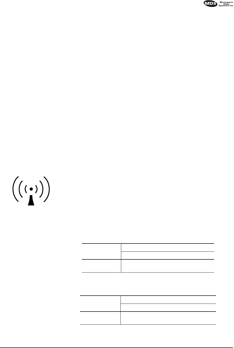
RF Exposure
Separation distances
required for FCC RF
Exposure compliance
Antenna Gain vs. Recommended Safety Distance
(MDS 4710 Series)
Antenna Gain (MDS 4710 Series)
0–5 dBi 5–10 dBi 10–16.5 dBi
Minimum RF
Safety Distance
0.79 meter 1.41 meters 3.05 meters
Antenna Gain vs. Recommended Safety Distance
(MDS 9710 Series)
Antenna Gain (MDS 9710 Series)
0–5 dBi 5–10 dBi 10–18.65 dBi
Minimum RF
Safety Distance
0.53 meter 0.94 meter 2.58 meters

iv MDS 4710/9710 I/O Guide MDS 05-3305A01, Rev. B
ISO 9001 Registration
Microwave Data Systems' adheres to this internationally accepted
quality system standard.
MDS Quality Policy Statement
We, the employees of Microwave Data Systems Inc., are committed to
understanding and exceeding our customer’s needs and expectations.
•We appreciate our customer’s patronage. They are our business.
•We promise to serve them and anticipate their needs.
•We are committed to providing solutions that are cost effective,
innovative and reliable, with consistently high levels of quality.
•We are committed to the continuous improvement of all of our
systems and processes, to improve product quality and increase
customer satisfaction.
FM/UL/CSA Notice
This product is available for use in Class I, Division 2, Groups A, B,
C & D Hazardous Locations. Such locations are defined in Article 500
of the National Fire Protection Association (NFPA) publication NFPA
70, otherwise known as the National Electrical Code.
The transceiver has been recognized for use in these hazardous locations
by three independent agencies —Underwriters Laboratories (UL), Fac-
tory Mutual Research Corporation (FMRC) and the Canadian Standards
Association (CSA). The UL certification for the transceiver is as a Rec-
ognized Component for use in these hazardous locations, in accordance
with UL Standard 1604. The FMRC Approval is in accordance with
FMRC Standard 3611. The CSA Certification is in accordance with
CSA STD C22.2 No. 213-M1987.
FM/UL/CSA Conditions of Approval:
The transceiver is not acceptable as a stand-alone unit for use in the haz-
ardous locations described above. It must either be mounted within
another piece of equipment which is certified for hazardous locations, or
installed within guidelines, or conditions of approval, as set forth by the
approving agencies. These conditions of approval are as follows:
3. The transceiver must be mounted within a separate enclosure which
is suitable for the intended application.
4. The antenna feedline, DC power cable and interface cable must be
routed through conduit in accordance with the National Electrical
Code.

MDS 05-3305A01, Rev. B MDS 4710/9710 I/O Guide v
5. Installation, operation and maintenance of the transceiver should be
in accordance with the transceiver's installation manual, and the
National Electrical Code.
6. Tampering or replacement with non-factory components may
adversely affect the safe use of the transceiver in hazardous loca-
tions, and may void the approval.
7. When installed in a Class I, Div. 2, Groups A, B, C or D hazardous
location, observe the following:
WARNING —EXPLOSION HAZARD—
Do not disconnect
equipment unless power has been switched off or the area is known
to be non-hazardous.
Refer to Articles 500 through 502 of the National Electrical Code
(NFPA 70) for further information on hazardous locations and approved
Division 2 wiring methods.
Revision Notice
While every reasonable effort has been made to ensure the accuracy of
this manual, product improvements may result in minor differences
between the manual and the product shipped to you. If you have addi-
tional questions or need an exact specification for a product, please con-
tact our Customer Service Team using the information at the back of this
guide. In addition, manual updates can often be found on the MDS Web
site at www.microwavedata.com.
Distress Beacon Warning
In the U.S.A., the 406 to 406.1 MHz band is reserved for use by distress
beacons. Since the MDS 4710A radio is capable of transmitting in this
band, take precautions to prevent the radio from transmitting between
406 to 406.1 MHz. This notice applies
only
to MDS 4710A Transceivers
used in the U.S.A.

vi MDS 4710/9710 I/O Guide MDS 05-3305A01, Rev. B