GE MDS INET900 MDS iNet 900 User Manual MDS iNET Installation Guide Draft 3 12 17 01
GE MDS LLC MDS iNet 900 MDS iNET Installation Guide Draft 3 12 17 01
GE MDS >
Contents
- 1. users manual
- 2. installation guide
installation guide
Installation Guide
Review Draft 3—12/17/01
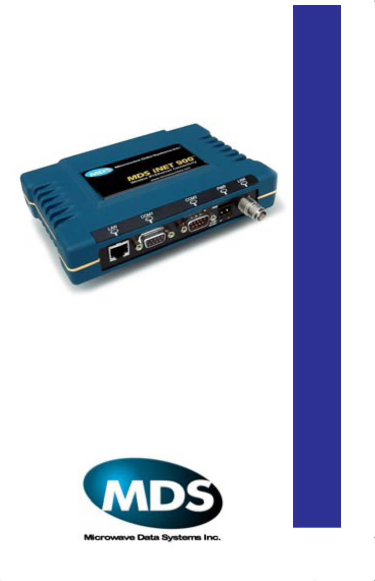
Wireless IP/Ethernet Transceiver
MDS 05-2873A01, REV. D3
DECEMBER 2001
MDS
i
NET
900
™

MDS 05-2873A01, Rev. D3 Installation Guide 1
Review Draft 3—12/17/01
CONTENTS
ABOUT THIS MANUAL............................................................4
PRODUCT DESCRIPTION......................................................4
INSTALLATION PLANNING.....................................................5
INSTALLATION ........................................................................6
Step 1—Mount the Transceiver....................................................6
Step 2—Install the Antenna .........................................................7
Step 3—Measure & Install Primary Power...................................7
Step 4—Review the Radio’s Configuration ..................................8
Step 5—Connect the Data Equipment.........................................9
Step 6—Check for Normal Operation ........................................10
Performance Optimization..........................................................10
TROUBLESHOOTING...........................................................11
iNET SPECIFICATIONS ........................................................13
IN CASE OF DIFFICULTY... ..................................................14
INSTALLATION REFERENCE CHART ............. (Center Insert)
Copyright Notice
This publication is protected by U.S. copyright law. Copyright 2001, Micro-
wave Data Systems, Inc. All rights reserved.
Serviceability of this Manual
While every reasonable effort has been made to ensure the accuracy of this manual,
product improvements may result in minor differences between the manual and the
product shipped to you. If you have additional questions or need an exact specification
for a product, please contact our Customer Service Team using the information at the
back of this guide. Microwave Data Systems Incorporated reserves its right to correct
any errors and omissions. Updated information may also be available on our Web site
at www.microwavedata.com.

2Installation Guide MDS 05-2873A01, Rev. D3
Review Draft 3—12/17/01
Operational Safety Notices
The radio equipment described in this guide emits
radio frequency energy. Although the power level
is low, the concentrated energy from a directional
antenna may pose a health hazard. Do not allow
people to come closer than two meters (6 feet) to
the antenna when the transmitter is operating.
This manual is intended to guide a professional installer in installing, oper-
ating and performing basic system maintenance on the described equipment.
FM/UL/CSA Notice
MDS
i
Net 900 When Approved
This product is available for use in Class I, Division 2, Groups A, B, C & D Hazardous
Locations. Such locations are defined in Article 500 of the National Fire Protection
Association (NFPA) publication NFPA 70, otherwise known as the National Elec-
trical Code.
The transceiver has been recognized for use in these hazardous locations by three
independent agencies —Underwriters Laboratories (UL), Factory Mutual Research
Corporation (FMRC) and the Canadian Standards Association (CSA). The UL certi-
fication for the transceiver is as a Recognized Component for use in these hazardous
locations, in accordance with UL Standard 1604. The FMRC Approval is in accor-
dance with FMRC Standard 3611. The CSA Certification is in accordance with CSA
STD C22.2 No. 213-M1987.
FM/UL/CSA Conditions of Approval
MDS
i
Net 900 When Approved
The transceiver is not acceptable as a stand-alone unit for use in the hazardous loca-
tions described above. It must either be mounted within another piece of equipment
which is certified for hazardous locations, or installed within guidelines, or conditions
of approval, as set forth by the approving agencies. These conditions of approval are
as follows:
1. The transceiver must be mounted within a separate enclosure which is suitable
for the intended application.
2. The antenna feedline, DC power cable and interface cable must be routed
through conduit in accordance with the National Electrical Code.
3. Installation, operation and maintenance of the transceiver should be in accor-
dance with the transceiver's installation manual, and the National Electrical
Code.
4. Tampering or replacement with non-factory components may adversely affect the
safe use of the transceiver in hazardous locations, and may void the approval.
RF Exposure

MDS 05-2873A01, Rev. D3 Installation Guide 3
Review Draft 3—12/17/01
Do not disconnect equipment unless power has
been switched off or the area is know to be
non-hazardous.
Refer to Articles 500 through 502 of the National
Electrical Code (NFPA 70) for further information
on hazardous locations and approved Division 2
wiring methods.
1
Z?
FCC Notice, U.S.A.
MDS
i
Net 900 When Approved
The MDS iNet 900 transceivers comply with Part 15 of the FCC Rules. Operation is
subject to the following two conditions: (1) this device may not cause harmful inter-
ference, and (2) this device must accept any interference received, including interfer-
ence that may cause undesired operation.
This device is specifically designed to be used under Section 15.247 of the FCC Rules
and Regulations. Any unauthorized modification or changes to this device without the
express approval of Microwave Data Systems may void the user’s authority to operate
this device.
Furthermore, this device is indented to be used only when installed in accordance with
the instructions outlined in this manual. Failure to comply with these instructions may
also void the user’s authority to operate this device.
FCC Information
This equipment has been tested and found to comply with the limits for a Class A dig-
ital device, pursuant to Part 15 of the FCC Rules. These limits are designed to provide
reasonable protection against harmful interference when the equipment is operated in
a commercial environment. This equipment generates, uses, and can radiate radio fre-
quency energy and, if not installed and used in accordance with the instruction
manual, may cause harmful interference to radio communications. Operation of this
equipment in a residential area is likely to cause harmful interference in which case
the user will be required to correct the interference at his own expense.
1. This seem like this note should be a DANGER classification if
there is a potential for an explosion. Please verify.
EXPLOSION
HAZARD!

4Installation Guide MDS 05-2873A01, Rev. D3
Review Draft 3—12/17/01
ABOUT THIS MANUAL
This guide presents installation and initial operating instructions for
the MDS
iNET
900™ transceiver. Following installation, we suggest
keeping this guide near the equipment for future reference.
The scope of this manual is limited to the safe and effective installation
of the unit in typical office or non-hazardous industrial settings. Users
who require optimization of the equipment’s capabilities and oper-
ating range should read the
MDS iNET 900 Network Administrator’s
Manual
, P/N 05-xxxxA01. This manual provides more in-depth infor-
mation on antenna selection and optimization, and extensive coverage
on user-controllable parameters and diagnostic tools.
Many of the essential installation information is contained on the
Installation Reference Chart
found at the center of this manual.
PRODUCT DESCRIPTION
The MDS
iNET
900 transceiver (shown on the cover) is a data radio
transceiver designed for to support wireless data networks.
The MDS
iNET
900 transceiver is designed to provide network man-
agers with a easy-to-install wireless local area network (LAN) services
with plug-and-play hardware. The unit can be reconfigured for any
one of three standard operating arrangements; some require the use of
electronic keys (alphanumeric code) purchased from MDS. The model
descriptions reflect their operating mode capabilities. The core data
interface services are 1. Ethernet, 2. Serial, and 3. Serial and Ethernet.
(See Table 1 on page 5 for a summary of core interface services.)
Three model configurations are available; they are:
1. Ethernet Bridge—Supports Ethernet traffic only
2. Serial gateway—Supports serial traffic only
(Encrypted over IP protocol)
3. Access Point/Dual Gateway—Supports Ethernet and serial data
simultaneously

MDS 05-2873A01, Rev. D3 Installation Guide 5
Review Draft 3—12/17/01
The MDS
iNET
900 transceivers serve as either an “Access Point” or
“Remote Gateway”. An Access Point is a wireless hub that provides
connectivity into a wired Ethernet LAN/WAN. From a radio perspec-
tive, an Access Point also serves as the radio network’s “master sta-
tion” providing synchronization signaling for associated
iNET
900
Remote Gateway radios.
INSTALLATION PLANNING
This section provides tips for selecting an appropriate site, choosing an
antenna system, and reducing the chance of harmful interference.
General Requirements
There are three main requirements for installing the radio—adequate
and stable primary power, a good antenna system, and the correct
interface between the transceiver and the data device. The center
Installation Reference Chart
shows a typical Remote Gateway instal-
lation.
Table 1.
i
NET 900 Models and Data Interface Services
Model Oper. Mode LAN Data
(IP/Ethernet) COM1
Data COM1
MGT Sys.
Access
COM2
Data
Ethernet
Bridge
1
Remote
Gateway Yes No Yes No
Serial
1
Remote
Gateway No Yes Yes Yes
Dual
Gateway
2
Remote
Gateway &
Access
Point
Yes Yes Yes Yes
NOTES
1. Firmware key required to convert to alternate operating modes:
Remote Serial/LAN Gateway, Ethernet Bridge, or Access Point Oper-
ation.
2. Default: Remote Serial/LAN Gateway. Able to be converted to Access
Point without firmware key

6Installation Guide MDS 05-2873A01, Rev. D3
Review Draft 3—12/17/01
Access Point stations are similar, but typically they use an omni-direc-
tional antenna and a Local-Area Network (LAN) or a Wide-Area Net-
work connected to the LAN port. The Access Point iNET radio
provides a connection to the wired network for devices attached to the
Remote Gateways.
Antennas are a vital link in the system; they must be chosen and
installed correctly. The
MDS iNET 900 Network Manager’s Manual
provides details on choosing a site and making antenna selections
INSTALLATION
A typical transceiver product shipment consists of an iNET 900 trans-
ceiver and a manual. Check the contents against the packing list
attached to the outside of the shipping box.
Below are the basic steps for installing a
i
NET 900 transceiver. Should
further information be required, see “IN CASE OF DIFFICULTY...”
on page 14 of this manual for information on contacting the factory.
You will also find support information at the Microwave Data System
Web site at www.MicrowaveData.com on the Internet.
NOTE:
It is recommended that the Access Point station be installed
first.
In this way, it will be possible to quickly check the
operation of each associated Remote Gateway unit as it is
placed on the air.
MDS iNET
900 transceivers are shipped from the
factory set to the “Remote Gateway” mode unless they
are marked differently.
Step 1—Mount the Transceiver
Mount the transceiver to a stable surface. (Fasteners/anchors/screws
are not supplied unless specified when the order.) Four threaded holes
are located on the bottom of the radio that are suitable for connecting
mounting hardware. Use 6-32 x 1/4 inch screws to attach mounting
hardware to the bottom of the radio.
MDS 05-2873A01, Rev. D3 Installation Guide 7
Review Draft 3—12/17/01
Screws used to hold the mounting brackets to the radio should
be 5⁄16 inch (8 mm) long or shorter to prevent damage to the
radio’s internal PC board. If these screws are replaced for any
reason, the new screws must not exceed this length. The
radio’s case is made of a durable cast-aluminum, however, the
use of the wrong sized screws can damage the screw sockets
on the cover.
Step 2—Install the Antenna
The antenna and
i
NET 900 unit should be mounted with the antenna a
minimum of six inches (15 cm) from other equipment, especially
metallic objects.
NOTE:
Radio frequency energy generated by the
i
NET 900 can
interfere with the operation of nearby low-level RTU
circuits and change the reported values of the data being
monitored. For this reason, the antenna should be mounted
at least 10 feet (>3 meters) from the RTU, sensors and other
components of the system.
General information on the selection and installation of antenna sys-
tems is provided in the
MDS iNET 900 Network Manager’s Manual
.
Step 3—Measure & Install Primary Power
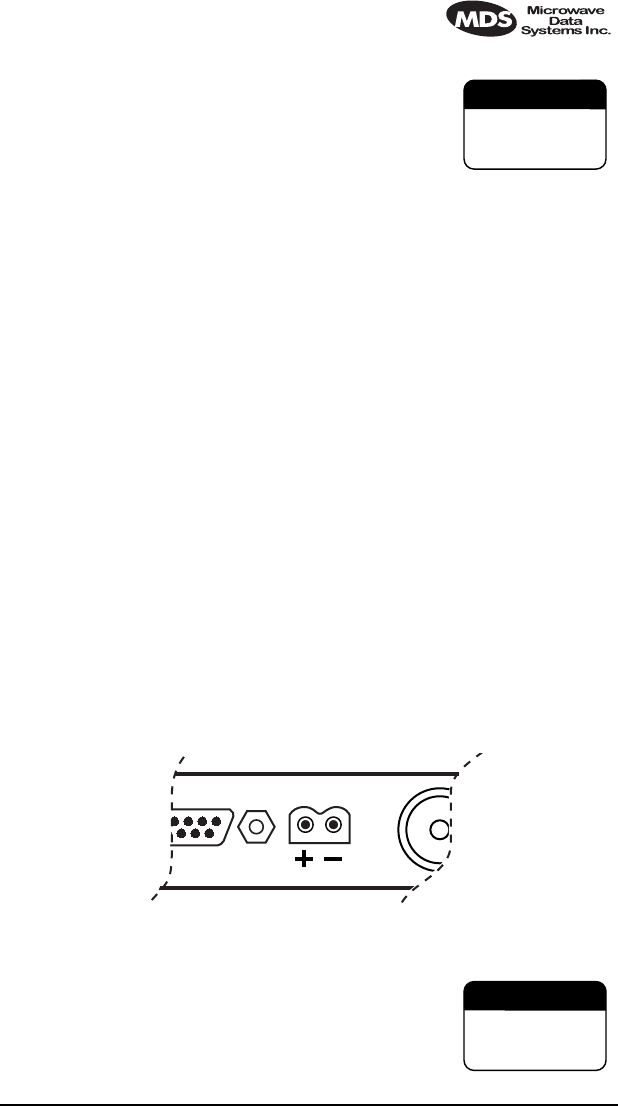
The primary power at the transceiver’s power connector must be
within 10.5–30 Vdc and be capable of continuously furnishing up to
500 mA. The optimum voltage is 13.8 Vdc. Be sure to observe proper
polarity as shown in Figure 1. A power connector is provided with
each radio suitable for use with pigtail leads.
Invisible place holder
Figure 1. Primary Power (DC) Polarity
The radio is designed to be used only in nega-
tive-ground systems. Make sure the polarity of the
power source is correct. Reverse polarity will dam-
age the
iNET
900’s circuitry and will result in per-
manent damage to the unit.
CAUTION
POSSIBLE
EQUIPMENT
DAMAGE
CAUTION
POSSIBLE
EQUIPMENT
DAMAGE

8Installation Guide MDS 05-2873A01, Rev. D3
Review Draft 3—12/17/01
The power supply used with the transceiver should be equipped with
overload protection (NEC Class 2 rating), to protect against a short cir-
cuit between its output terminals and the transceiver power connector.
Step 4—Review the Radio’s Configuration
There are two essential settings for
i
NET 900 transceivers that should
be known before placing the radio into service. They are:
Radio Operating Mode
—Access Point or Remote Gateway
Network Name—
Unique name of the radio network that is
used to generate the hopping pattern.
NOTE:
Transceivers are normally shipped from the factory config-
ured as a Remote Gateway.
Unit IP Address
—Must be a unique number to allow for IP
access through the Ethernet Port.
Transmitter Power Output Level
—Default is 1 Watt.
Adjust as necessary for compliance with FCC guidelines.
NOTE:
A unique IP address is important if the radio’s LAN
(Ethernet) port will be used for IP-based data communica-
tions or for unit configuration.
NOTE:
The
COM1
port’s only function is to provide access to the
iNET 900’s management system. COM2 is not functional at
this time.
The following is a summary of the installation procedure. For more
detailed instructions on using the menu-based COM1 and the
HTTP/Bowser interfaces, please read the
MDS iNET 900 Network
Administrator’s Handbook
.
Procedure
a. Connect a personal computer’s serial communications port
(COM1 or COM2) to the
COM1
Port connector on the radio
transceiver. (See the I
nstallation Reference Chart
for location.
Data defaults: 19,200 kbs/8N1.)
b. Launch a terminal emulator program, such as HyperTerminal,
on the computer.
c. Depress the
ENTER
key. The radio will respond with the
start-up screen of a text-based Management System.

MDS 05-2873A01, Rev. D3 Installation Guide 9
Review Draft 3—12/17/01
d. A login with password will be required to make any changes
to the radio. (Default =
admin
)
e. Select the desired options to review existing settings and to
initiate necessary changes such as the IP address and other
network parameters. Changes are saved in the unit’s flash
memory.
f. Repeat the above steps for each transceiver in the network.
Basic
i
NET Unit Parameter Defaults
The table on the center
Installation Reference Chart
provides a sum-
mary of basic operating parameter’s range of and default values. All
of these are available through the
i
NET’s Management System acces-
sible through a terminal emulator connected to the
COM1
port.
Step 5—Connect the Data Equipment
Connect Ethernet/IP-compatible equipment data equipment to the
transceiver’s LAN port. The port supports only 10BaseT.
Use only the required pins for the application—do not connect any-
thing to unused pins. Use a straight-through Ethernet cable to connect
to a hub or a crossover cable to connect directly to an Ethernet station
or RTU. See the
Installation Reference Chart
in the middle of this
guide for pinout information.
Remote Gateway
—If the radio network seems to be operating prop-
erly based on observation of the unit’s LEDs, connect the user data
equipment to the LAN port. Use the IP
PING
command to verify the
communications link integrity with the Access Point unit.
Access Point
—Connect the WAN/LAN to the LAN port of the radio.
LED Indicators
A table of LED functions can be found on the center
Installation Ref-
erence Chart
.

10 Installation Guide MDS 05-2873A01, Rev. D3
Review Draft 3—12/17/01
Step 6—Check for Normal Operation
a. Observe the transceiver LED status panel (See the
Installation
Reference Chart
) for the proper indications. In a normally
operating system, the following LED indications will be seen
within 30 seconds of start-up:
•
PWR—
Lit continuously
•
LINK
—Blinks intermittently at Remote Gateways and contin-
uously on Access Point stations.
•
LAN
—On indicates it connected to a good Ethernet cable.
Blinks (flickers) with data activity.
b. Check the received signal strength indicator (RSSI) for an
adequate signal level from the radio network’s Access Point
station. (RSSI available through the iNET Management Sys-
tem) It may be necessary to reposition the gateway radio’s
antenna for better reception/signal strength, or if a directional
antenna is used, rotate it until the signal is optimized.
See the
Installation Reference Chart
for details on the LED functions
and chart of Management System menus.
If all checks out OK, you are done with the installation. Congratula-
tions!
Performance Optimization
After the basic operation of the radio has been checked, you may wish
to optimize its performance using some of the suggestions given here.
The effectiveness of these techniques will vary with the design of your
system and the format of the data being sent.
Complete instructions on using the unit’s configuration options refer-
enced within this section are can be found in the MDS iNET 900 Net-
work Manager’s Manual.

MDS 05-2873A01, Rev. D3 Installation Guide 11
Review Draft 3—12/17/01
TROUBLESHOOTING
It is best to begin troubleshooting at the Access Point station, as the
rest of the system depends on the Access Point for polling instructions
and synchronization data. If the Access Point station has problems, the
operation of the entire network will be affected.
All radios in the network must meet these basic requirements:
•Adequate and stable primary power
•An efficient and properly aligned antenna system
• Secure connections (RF, data & power)
• Proper programming of the radio’s operating parameters,
especially Mode selection (Access Point/Remote), Network
Name, and IP Network Address
• The correct interface between the radio and the connected
data equipment (proper cable wiring, data format and timing).
Table 2 on page 12 provides suggestions for resolving system difficul-
ties that may be experienced in the radio system. If problems persist,
contact the factory for further assistance. Refer to the inside back
cover of this guide for contact information.

12 Installation Guide MDS 05-2873A01, Rev. D3
Review Draft 3—12/17/01
Table 2. Troubleshooting Techniques
Difficulty Recommended System Checks
The PWR LED
does not turn on. a. Check for the proper supply voltage at the power
connector.
b. Cycle the power and wait for the unit to reboot.
(≈ 30 seconds)
Interference is
suspected. a. Verify that the system has a unique network name.
A nearby systems (Access Point station) with the
same network name will cause interference.
b. If omnidirectional antennas are used on, consider
changing to directional antennas. This will often
limit interference to and from other stations.
c. The installation of a filter in the antenna line may
be necessary. Consult the factory for further
assistance.
The LINK LED
does not turn on. a. Check for secure interface connections at the radio
and the connected device.
b. Check the antenna, feedline and connectors.
Reflected power should be less than 10% of the
forward power reading (SWR ≈2:1 or lower).
c. No synchronization with Access Point, or poor
overall performance. Check RSSI level.
Cannot pass IP
data to WAN. a. Use the PING command to test communication
with iNET units in the local radio system.
b. If successful with local PING, attempt to PING an
IP unit attached to an iNET radio.
c. If successful with the LAN PINGs, try connecting to
a known unit in the WAN.

MDS 05-2873A01, Rev. D3 Installation Guide 13
Review Draft 3—12/17/01
INET SPECIFICATIONS
GENERAL
Temperature Range: –30°C to +70°C (–22° F to 158° F)
Humidity: 95% at +40°C (104° F); non-condensing
Primary Power: 10.5–30 Vdc(13.8 Vdc Nominal)
External Power Supply Options: 48 Vdc; 110–120/210–220 Vac
Supply Current (typical): (@1 Watt RF Output)
Transmit: 500 mA @ 13.8 Vdc
Size (Excluding mtg. hardware): 1.5" x 6" x 4" (H x W x D)
3.8 x 15.2 x 10.2 cm
Weight: 0.9 kg / 2 lb
Case: Cast Aluminum
Shock and Vibration: Meets MIL STD 202F, 810E, 202D
RADIO CHARACTERISTICS
GENERAL:
Frequency Range: 902–928 MHz ISM Band
Mode: Freq. Hopping Spread-Spectrum (FHSS)
TRANSMITTER:
Power Output
(at antenna connector): 0.1 to 1.0 watt (+20 dBm to +30 dBm)
Increments of1.0 dB, set by user
Duty Cycle: Continuous
Output Impedance: 50 Ohms
RECEIVER:
Type: Double conversion superheterodyne
Sensitivity: –92 dBm @ 512 kbps < 1x10⁻⁶ BER
–100 dBm @ 256 kbps < 1x10⁻⁶ BER
Time Required to Synchronize
with Access Point Radio: Less than 13 seconds (typical)

14 Installation Guide MDS 05-2873A01, Rev. D3
Review Draft 3—12/17/01
IN CASE OF DIFFICULTY...
MDS products are designed for long life and trouble-free opera-
tion. However, this equipment, as with all electronic equipment
may have an occasional component failure. The following infor-
mation will assist you in the event that servicing becomes neces-
sary.
TECHNICAL ASSISTANCE
Technical assistance for MDS products is available from our Cus-
tomer Support Team during business hours (8:00 A.M.–5:30 P.M.
Eastern Time). When calling, please give the complete model number
of the radio, along with a description of the trouble symptom(s) that
you are experiencing. In many cases, problems can be resolved over
the telephone, without the need for returning the unit to the factory.
Telephone 1+ 585-242-8510 for product assistance or visit the tech-
nical support area of the Microwave Data Systems’ Web site at
www.MicrowaveData.com.
FACTORY SERVICE
If return of the equipment is necessary, please contact the MDS Cus-
tomer Support Team. You will be issued a Returned Material Autho-
rization (RMA) number. The RMA number will help expedite the
repair so that the equipment can be repaired and returned to you as
quickly as possible. Please be sure to include the RMA number on the
outside of the shipping box, and on any correspondence relating to the
repair. No equipment will be accepted for repair without an RMA
number.
A statement should accompany the radio describing, in detail, the
trouble symptom(s), and a description of any associated equipment
normally connected to the radio. It is also important to include the
name and telephone number of a person in your organization who can
be contacted if additional information is required.

MDS 05-2873A01, Rev. D3 Installation Guide 15
Review Draft 3—12/17/01
The radio must be properly packed for return to the factory. The orig-
inal shipping container and packaging materials should be used when-
ever possible. All factory returns should be addressed to:
When repairs have been completed, the equipment will be returned to
you by the same shipping method used to send it to the factory. Please
specify if you wish to make different shipping arrangements.
Microwave Data Systems Inc.
Customer Service Department
(RMA No. XXXX)
175 Science Parkway
Rochester, NY 14620 USA

175 Science Parkway, Rochester, New York 14620
General Business: +1 (716) 242-9600
FAX: +1 (716) 242-9620
Web: www.microwavedata.com