GE MDS INET900 MDS iNet 900 User Manual 2873F iNet Body
GE MDS LLC MDS iNet 900 2873F iNet Body
GE MDS >
Contents
- 1. users manual
- 2. installation guide
users manual
MDS 05-2873A01, REV. FCC
AUGUST 2001
Wireless IP/Ethernet Transceiver
MDS iNet 900™

DRAFT 6—8/30/01
Below are the basic steps for installing the MDS iNet 900 transceiver. Detailed instructions are given in
the Section 3.0,
INSTALLATION PLANNING
, on page 5 of this manual.
1. Install and connect the antenna system to the radio
• Use good quality, low-loss coaxial cable. Keep the feedline as short as possible.
• Preset directional antennas in the direction of desired transmission/reception.
2. Apply DC power to the radio (13.8 Vdc @ 500 mA)
• Connect a DC power source to the
i
Net’s power connector.(Negative ground only.)
• Observe proper polarity when connecting the DC cable. See Figure 10 on page 16.
3. Review the initial configuration profile
• Connect a computer with HTTP browser to the LAN port, or a terminal to the COM1 port, to identify,
and revise if necessary the MDS
i
Net 900’s primary operating parameters. (See “Step 5—Review
the Radio’s Configuration” on page 16 for details.)
✓
Operating Mode: Access Point (Master) or Station Adaptor (Remote)
✓
Internet Protocol (IP) Address
✓
Network Name
✓
Time and Date—If event logging is enabled
1
Z?
4. Verify proper operation of the MDS
i
Net radio-modem
• See Table 2 on page 7 for an explanation of the LED status indicators.
• Refine the antenna heading for maximum received signal strength using the radio signal strength
indicator (
RSSI
) function found on the browser’s home page. The RSSI display will be in dBm.
5. Connect the user’s equipment to the MDS
i
Net’s LAN, COM1or COM2 ports
• LAN—Use a RJ-45 Ethernet connector/cable.
• COM2—Recommended for serial-based data equipment.
Use a DB-9 female connector. Interface is RS-232/EIA-232 compatible.
• COM1—Reserve, if practical, for use to connect terminal for unit configuration.
Use a DB-9 male connector. Interface is RS-232/EIA-232 compatible.
(See Table 9 on page 34 for pin descriptions and Figure 9 on page 16 for port defaults.)
6. Verify proper operation of the user’s equipment
• A properly configured system will work exactly as it would if the data equipment were communicating
through a conventional wired system. (See Table 4.6 on page 18)
• The LINK LED will blink intermittently under normal operation if it connects with another
MDS iNet 900 transceiver.
• Use the IP “PING” command to verify the Access Point can be contacted by the Station Adapter.
1. While this may be of value, the time and date setting does not seem like a primary parameter and is
beyond the scope of this draft.
QUICK START GUIDE
DRAFT 6—8/30/01

MDS 05-2873A01, Rev. A MDS
i
Net 900 Installation and Operation Guide i
DRAFT 6—8/29/01
TABLE OF CONTENTS
1.0 ABOUT THIS MANUAL................................................................1
2.0 PRODUCT DESCRIPTION .........................................................1
2.1 Transceiver Features ........................................................................2
2.2 Spread Spectrum Radios—
How Are They Different? ..........................................................................3
2.3 Typical Applications ..........................................................................3
Wireless IP/Ethernet LAN Connectivity ..........................................3
Point-to-Point System .....................................................................3
Dealing with difficult terrain.............................................................4
2.4 Accessories ......................................................................................4
3.0 INSTALLATION PLANNING.........................................................5
3.1 General Requirements .....................................................................5
3.2 Site Selection ...................................................................................6
Terrain and Signal Strength ............................................................6
Conducting a Site Survey ...............................................................7
3.3 A Word About Radio Interference ....................................................8
3.4 Antenna & Feedline Selection ..........................................................9
Antennas ........................................................................................9
Feedlines ......................................................................................11
3.5 How Much Output Power Can be Used? .......................................11
Calculating System Gain ..............................................................12
4.0 INSTALLATION ..........................................................................13
4.1 Step 1— Mounting the Transceiver ................................................13
4.2 Step 2—Install the Antenna and Feedline ......................................15
4.3 Step 3—Connect the Data Equipment ...........................................15
4.4 Step 4—Measure & Install Primary Power .....................................16
4.5 Step 5—Review the Radio’s Configuration ....................................16
Procedure .....................................................................................17
4.6 Step 6—Connect the User Data Equipment ..................................18
4.7 Step 7—Check for Normal Operation ............................................18
Procedure .....................................................................................18
4.8 Performance Optimization ..............................................................19
Antenna Aiming ............................................................................19
Antenna SWR Check (Z? Major revision needed?)......................20
5.0 TRADITIONAL REPEATER CONFIGURATION WITH TWO RADIOS
20
5.1 Overview ........................................................................................20

ii MDS
i
Net 900 Installation Guide MDS 05-2873A01, Rev. A
DRAFT 6—8/29/01
5.2 Antennas ........................................................................................21
5.3 Network Name ...............................................................................21
5.4 Interface Wiring ..............................................................................21
6.0 PROGRAMMING.......................................................................21
6.1 Programming Via an HTTP/Web Browser ......................................22
Making the Connection.................................................................22
Start-up Screen ............................................................................22
System Configuration Screen.......................................................23
Radio/Modem Screen Z?..............................................................23
6.2 Programming Via COM1 Port & a Terminal Program .....................24
Making the Connection.................................................................24
Communicating with the iNet transceiver .....................................24
Using the Menu-Based Management Toolbox..............................24
Review and Changing Essential Parameters................................26
7.0 TROUBLESHOOTING ...............................................................26
7.1 LED Indicators ................................................................................27
7.2 Troubleshooting Chart ....................................................................27
8.0 REPEATER ASSITED LANS .....................................................28
Repeater Systems ........................................................................28
Option 1—Traditional with two-radio repeater ..............................28
Option 2—With Store-and-Forward Station..................................29
9.0 TECHNICAL REFERENCE .......................................................30
9.1 Technical Specifications .................................................................30
9.2 Data Interface Connectors—
LAN, COM1 & DATA Ports .....................................................................32
LAN (Local Area Network) Port—RJ-45 Ethernet Interface..........32
COM1 Port ...................................................................................33
COM2 Port....................................................................................34
9.3 Table-Top Test Setup ......................................................................34
9.4 Using a Personal Computer to Configure the iNet Radio ...............35
Connecting a PC to iNet’s LAN (Ethernet) Port............................35
Connecting a PC to iNet’s COM1 Port..........................................35
10.0 GLOSSARY OF TERMS..........................................................36
10.1 dBm-Watts-Volts Conversion Chart ..............................................39
Copyright Notice
This Installation and Operation Guide and all software described herein
are protected by copyright. Copyright 2001, Microwave Data Systems,
Inc. All rights reserved.

MDS 05-2873A01, Rev. A MDS
i
Net 900 Installation and Operation Guide iii
DRAFT 6—8/29/01
Serviceability of this Manual
While every reasonable effort has been made to ensure the accuracy of
this manual, product improvements may result in minor differences
between the manual and the product shipped to you. If you have addi-
tional questions or need an exact specification for a product, please con-
tact our Customer Service Team using the information at the back of this
guide. Microwave Data Systems Incorporated reserves its right to cor-
rect any errors and omissions. Updated information may also be avail-
able on our Web site at www.microwavedata.com.
Operational Safety Notices
The radio equipment described in this guide emits radio frequency
energy. Although the power level is low, the concentrated energy from
a directional antenna may pose a health hazard. Do not allow people to
come within two meters (6 feet) of the antenna when the transmitter is
operating.
This manual is intended to guide a professional installer in installing,
operating and performing basic system maintenance on the described
equipment.
FM/UL/CSA Notice
MDS
i
Net 900 When Approved
This product is available for use in Class I, Division 2, Groups A, B,
C & D Hazardous Locations. Such locations are defined in Article 500
of the National Fire Protection Association (NFPA) publication NFPA
70, otherwise known as the National Electrical Code.
The transceiver has been recognized for use in these hazardous locations
by three independent agencies —Underwriters Laboratories (UL), Fac-
tory Mutual Research Corporation (FMRC) and the Canadian Standards
Association (CSA). The UL certification for the transceiver is as a Rec-
ognized Component for use in these hazardous locations, in accordance
with UL Standard 1604. The FMRC Approval is in accordance with
FMRC Standard 3611. The CSA Certification is in accordance with
CSA STD C22.2 No. 213-M1987.
FM/UL/CSA Conditions of Approval
MDS
i
Net 900 When Approved
The transceiver is not acceptable as a stand-alone unit for use in the haz-
ardous locations described above. It must either be mounted within
another piece of equipment which is certified for hazardous locations, or
installed within guidelines, or conditions of approval, as set forth by the
approving agencies. These conditions of approval are as follows:
1. The transceiver must be mounted within a separate enclosure which
is suitable for the intended application.
RF Exposure

iv MDS
i
Net 900 Installation Guide MDS 05-2873A01, Rev. A
DRAFT 6—8/29/01
2. The antenna feedline, DC power cable and interface cable must be
routed through conduit in accordance with the National Electrical
Code.
3. Installation, operation and maintenance of the transceiver should be
in accordance with the transceiver's installation manual, and the
National Electrical Code.
4. Tampering or replacement with non-factory components may
adversely affect the safe use of the transceiver in hazardous loca-
tions, and may void the approval.
5. When installed in a Class I, Div. 2, Groups A, B, C or D hazardous
location, observe the following:
Do not disconnect equipment unless power has been
switched off or the area is know to be non-hazardous.
Refer to Articles 500 through 502 of the National Electrical
Code (NFPA 70) for further information on hazardous loca-
tions and approved Division 2 wiring methods.
1
Z?
FCC Notice, U.S.A.
MDS
i
Net 900 When Approved
The MDS iNet 900 transceivers comply with Part 15 of the FCC Rules.
Operation is subject to the following two conditions: (1) this device may
not cause harmful interference, and (2) this device must accept any
interference received, including interference that may cause undesired
operation.
This device is specifically designed to be used under Section 15.247 of
the FCC Rules and Regulations. Any unauthorized modification or
changes to this device without the express approval of Microwave Data
Systems may void the user’s authority to operate this device.
Furthermore, this device is indented to be used only when installed in
accordance with the instructions outlined in this manual. Failure to
comply with these instructions may also void the user’s authority to
operate this device.
FCC Information
This equipment has been tested and found to comply with the limits for
a Class A digital device, pursuant to Part 15 of the FCC Rules. These
limits are designed to provide reasonable protection against harmful
interference when the equipment is operated in a commercial environ-
1. This seem like this note should be a DANGER classification if there is a
potential for an explosion. Please verify.
EXPLOSION
HAZARD

MDS 05-2873A01, Rev. A MDS
i
Net 900 Installation and Operation Guide v
DRAFT 6—8/29/01
ment. This equipment generates, uses, and can radiate radio frequency
energy and, if not installed and used in accordance with the instruction
manual, may cause harmful interference to radio communications.
Operation of this equipment in a residential area is likely to cause
harmful interference in which case the user will be required to correct
the interference at his own expense.

MDS 05-2873A01, Rev. A MDS
i
Net 900 Installation and Operation Guide 1
DRAFT 6—8/29/01
1.0 ABOUT THIS MANUAL
This guide presents installation and basic operating instructions for the
MDS
i
Net 900™ transceiver. Following installation, we suggest
keeping this guide near the equipment for future reference.
The terms Access Point and Station Adapter are abbreviated as “
A.P.”
and “
S.A.”
in various technical illustrations and tables used in this
manual wherever space is at a premium.
This manual does not cover all possible MDS iNet 900 user-controllable
parameters and/or diagnostic tools. For an in-depth description of all of
the features and controls of the MDS iNet 900, please read the
MDS iNet Network Manager’s Manual
, P/N 05-xxxxA01.
2.0 PRODUCT DESCRIPTION
The MDS
i
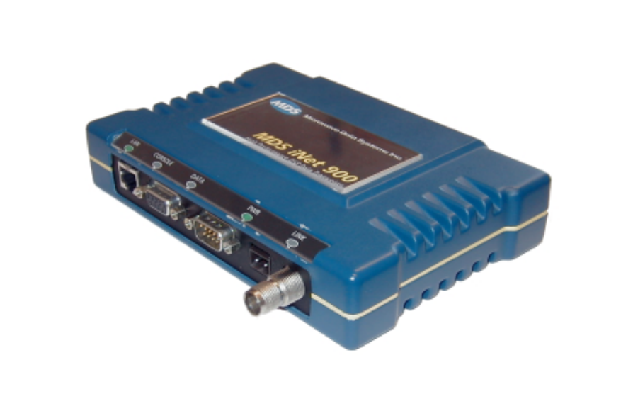
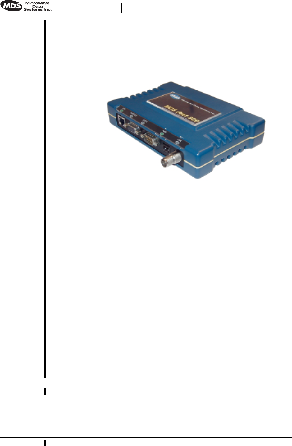
Net 900 transceiver, shown in Figure 1, is designed to pro-
vide network managers with a easy-to-install wireless local area net-
work (LAN) services with plug-and-play hardware. For basic services,
just hook up an antenna, connect your Ethernet LAN to the radio’s LAN
port, apply primary power, and you are done. And, no license is
required.
The transceiver is a spread-spectrum radio designed for operation in the
license-free 900 MHz frequency band. The MDS
i
Net 900 provides reli-
able communications up to distances of 30 miles (50 km), even in the
presence of weak signals or interference.
Only two user-controllable parameters need to be checked at the time of
installation—the radio’s Access Point/Station Adapter operating mode,
and “network name” of the unit.
The MDS
i
Net 900 transceiver is based on the IEEE 802.11 wireless
LAN specification. From this perspective,
i
Net transceivers serve as
“Access Points” and “Station Adapters”. An Access Point is a wireless
hub that provides connectivity into a wired Ethernet LAN. This connec-
tivity is achieved through remote Station Adapters. From a radio per-
spective, an Access Point also works as a “master station” providing
synchronization signaling for the remote radios (Access Point units).
A Station Adapter provides wireless connectivity to and Access Point to
one or more Ethernet devices connected to its local interface. From a
radio perspective, the Station Adapter also works as a remote radio that
communicates to a master radio (Access Point).
2 MDS
i
Net 900 Installation Guide MDS 05-2873A01, Rev. A
DRAFT 6—8/29/01
Users with a mixture of equipment with Ethernet and serial data inter-
faces can choose to use one of the two user-configurable serial ports.
This flexibility allows the iNet transceiver to provide services in data
networks that are on a path from legacy serial/EIA/RS-232-based hard-
ware to the faster and more easily interfaced Ethernet world. The radio
and data interfaces are easily arranged via the
COM1
port or via the
LAN
(Ethernet) port using HTTP.
Figure 1. The MDS iNet 900 Transceiver
The transceiver is housed in a compact and rugged cast-aluminum case
that needs only be protected from direct exposure to the weather. It con-
tains a single printed circuit board with all necessary components for
radio operation and data communications.
2.1 Transceiver Features
Listed below are several key features of the MDS
i
Net 900 transceivers.
These are designed to ease the installation and configuration of the
radio, while retaining the ability to make changes in the future.
• Plug-and-Play Connectivity—Ethernet bridge configuration
option requires virtually no setup
• High Speed—512 kbps is 50-times faster than 9.6 kbps radios
• Long Range—30 miles (50 km) in wireless LAN configuration
• Robust Radio Communications—Designed to operate in
high-interference environments
• Industrial-Grade Product—Extended temperature range for
trouble-free operation in extreme environments
• Serial Ports—IP gateway to legacy serial interface based equip-
ment
• Same hardware for Access Point and Station Adaptor configu-
rations
MDS 05-2873A01, Rev. A MDS
i
Net 900 Installation and Operation Guide 3
DRAFT 6—8/29/01
2.2 Spread Spectrum Radios—
How Are They Different?
The main difference between a traditional (licensed) radio system and
the
i
Net transceivers is that these units “hop” from channel to channel
many times per second using a specific hop pattern applied to all radios
in the network. A distinct hopping pattern is provided for each of the
network name, thereby minimizing the chance of interference with other
spread spectrum systems. In the USA, and certain other countries, no
license is required to install and operate this type of radio system.
2.3 Typical Applications
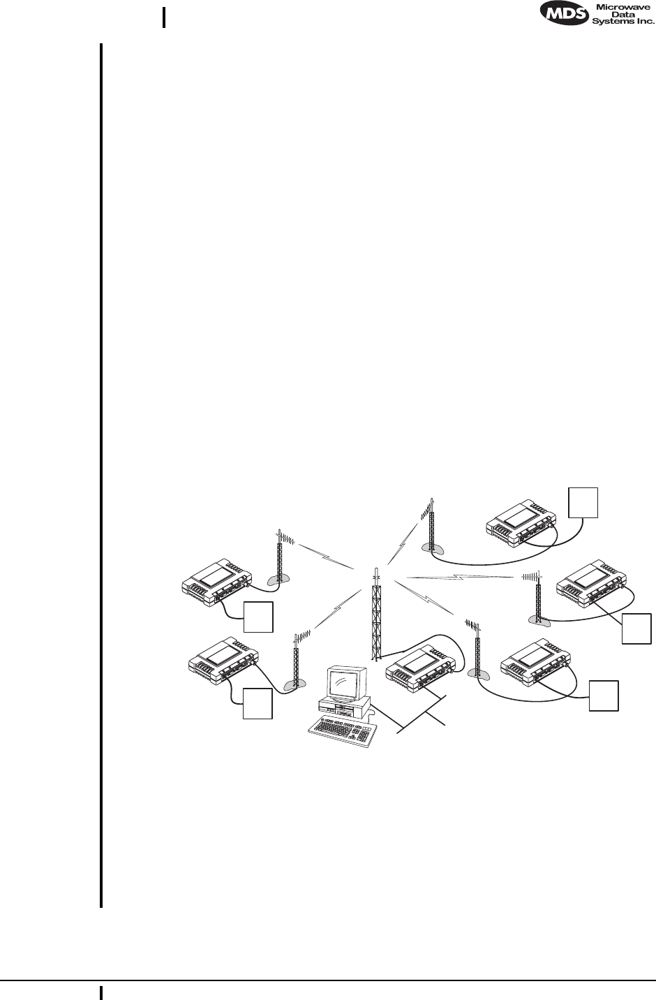
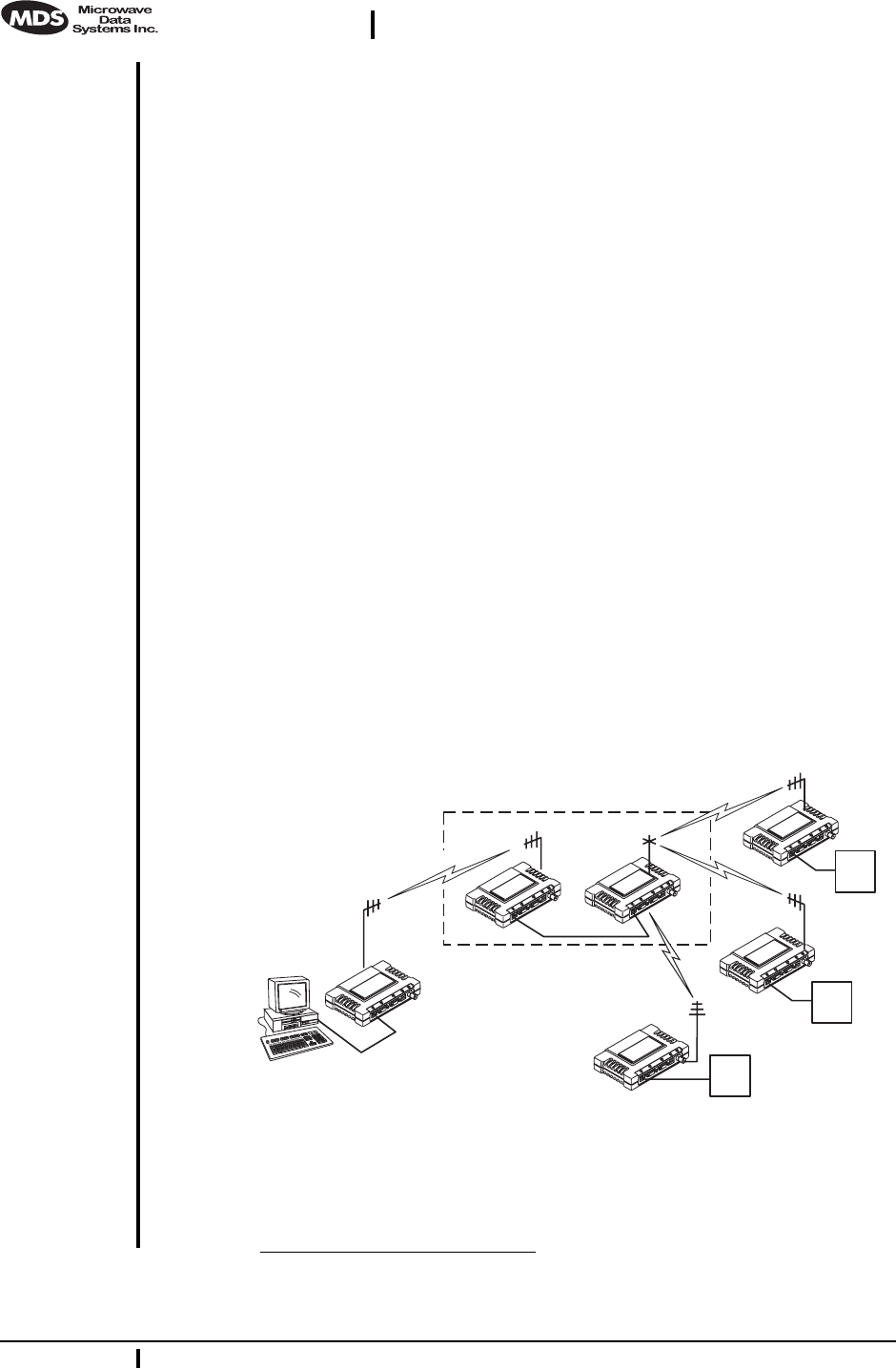
Wireless IP/Ethernet LAN Connectivity
This is the most common application of the MDS
i
Net 900 transceiver.
It consists of a central control station (Access Point) and one or more
associated Station Adapter units, as shown in Figure 2. A LAN provides
communications between a central host computer and remote terminal
units (RTUs) or other data collection devices. The operation of the radio
system is transparent to the computer equipment with the Access Point
station serving as the gateway to the WAN or host computer.
Invisible place holder
Figure 2. Typical wireless LAN
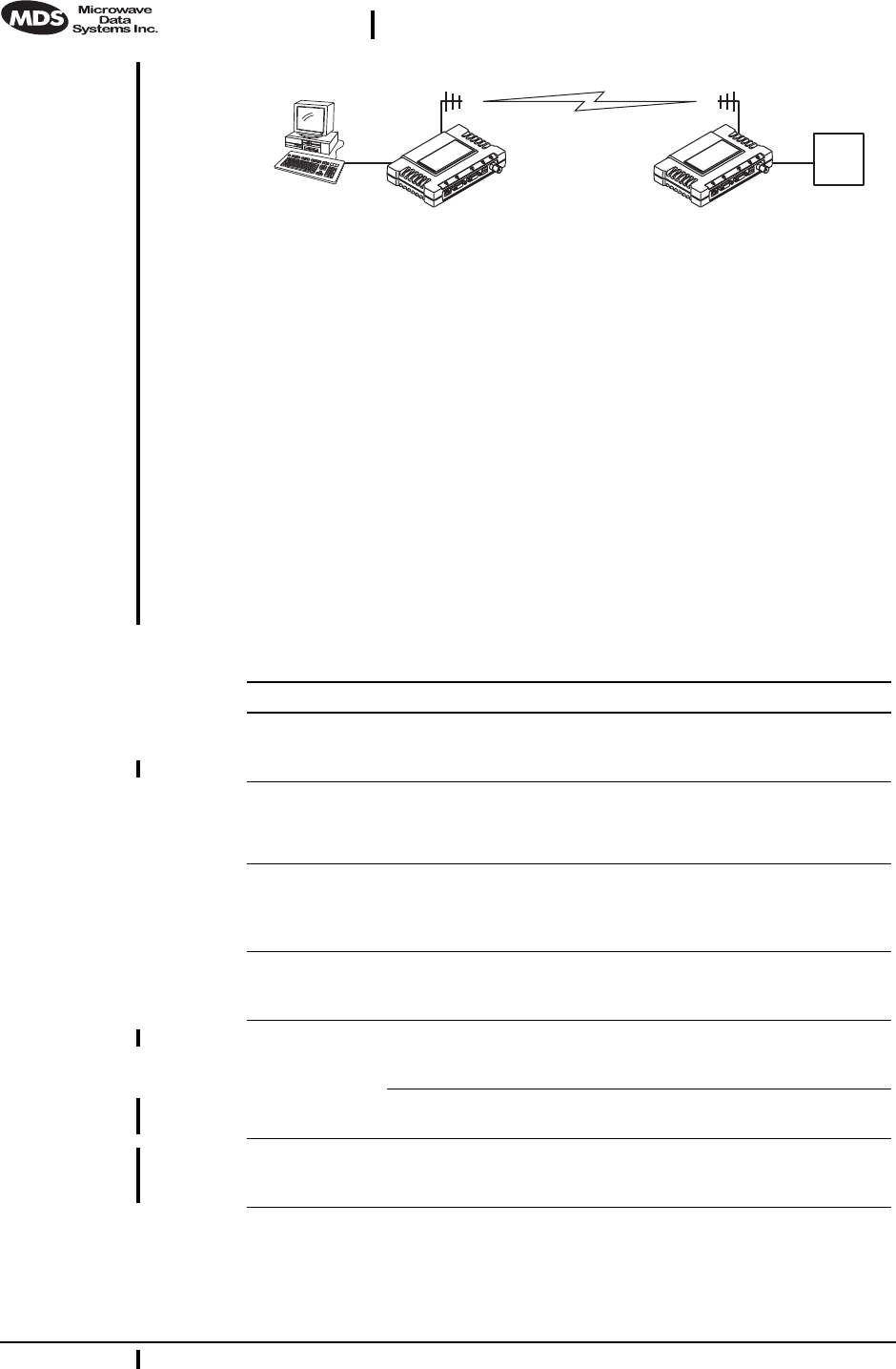
Point-to-Point System
A point-to-point configuration (Figure 3) is a simple arrangement con-
sisting of just two radios—a Access Point and a Station Adapter. This
provides communications link for the transfer of data between two loca-
tions.
iNet S.A.
iNet S.A.
iNet S.A.
iNet A.P.
iNet S.A.
iNet S.A.
HOST
COMPUTER
RTU
RTU
RTU
RTU
RTU
4 MDS
i
Net 900 Installation Guide MDS 05-2873A01, Rev. A
DRAFT 6—8/29/01
Invisible place holder
Figure 3. Typical point-to-point link
(A LAN connection may be used in place of a Host Computer)
Dealing with difficult terrain
In some geographical areas there may be obstacles that make communi-
cation between iNet transceivers difficult. These obstacles commonly
are large buildings, natural geological formations or dense foliage.
These obstacles can often be overcome with a repeater station. See
“REPEATER ASSITED LANS” on page 28 for descriptions of basic
repeater configurations.
2.4 Accessories
The MDS iNet 900 transceiver can be used with one or more of the
accessories listed in Table 1. Contact the factory for ordering details.
RTU
HOST
COMPUTER iNet A.P. iNet S.A.
Table 1. Accessories
Accessory Description MDS P/N
A/C Power
Adapter A small switching power supply module
designed for continuous service. UL approved.
Output 13.8 Vdc @ 500 mA.s
03-xxxxA01
LAN Antenna Small and flexible 1/4 wavelength antenna
plugged directly into the radio’s ANTENNA
port. Suitable for short-range local area
networks.
03-xxxxA01
TNC to N
Adapter Short length of coaxial cable (6”/15 cm) used to
connect the radio’s TNC antenna connector to
a Type N commonly used on large diameter
coaxial cables.
03-xxxxA01
Ethernet RJ-45
Cross-over
Cable
Cable assembly used to cross-connect the
Ethernet ports of two iNet radios used in a
repeater configuration. (Cable length = 3’/1M)
03-xxxxA01
Flat-Surface
Mounting
Brackets
Brackets: 2” x 3” plates designed to be screwed
onto the bottom of the transceiver for
surface-mounting the radio.
82-1753-A01
Screws: 6-32/1/4˝ with locking adhesive.
(Industry Standard MS 51957-26) 70-2620-A01
19˝ Rail
Mounting
Brackets
Adaptor for mounting one MDS iNet 900 radio
in a standard 19-inch equipment rack. 03-xxxxA01
MDS 05-2873A01, Rev. A MDS
i
Net 900 Installation and Operation Guide 5
DRAFT 6—8/29/01
3.0 INSTALLATION PLANNING
The installation of the radio is not difficult, but it does require some
planning to ensure station reliability and efficiency. This section pro-
vides tips for selecting an appropriate site, choosing an antenna system,
and reducing the chance of harmful interference.
3.1 General Requirements
There are three main requirements for installing the radio—adequate
and stable primary power, a good antenna system, and the correct inter-
face between the transceiver and the data device.
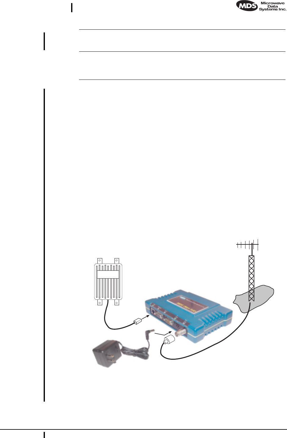
Figure 4 shows a typical Station Adapter installation. An external direc-
tional antenna is normally used and an RTU/PLC is connected to one of
the serial ports (COM1/COM2). 13.8 Vdc is supplied to the Station
Adapter by an external source.
Invisible place holder
Figure 4. Typical Station Adapter arrangement
(RTU can be connected to any compatible LAN or COM Port)
DIN Rail
Mounting
Brackets
Adaptor for mounting one MDS iNet 900 radio
in a DIN standard equipment rack. 03-xxxxA01
Short-Range
Antenna Short 1/2-wave antenna. Mounts directly onto
the radio’s coaxial connector. Suitable only for
short-range LANs, such as within a building or
small campus.
03-xxxxA01
Table 1. Accessories
(Continued)
LAN PORT
POWER SUPPLY
13.6 VDC @
500 mA (MIN.)
REMOTE
TERMINAL
UNIT
ANTENNA
SYSTEM
LOW-LOSS FEEDLINE
iNet RADIO
TRANSCEIVER

6 MDS
i
Net 900 Installation Guide MDS 05-2873A01, Rev. A
DRAFT 6—8/29/01
3.2 Site Selection
For a successful installation, careful thought must be given to selecting
proper sites for the Access Points and Station Adapters. Suitable sites
should provide:
• Protection from direct weather exposure
• A source of adequate and stable primary power
• Suitable entrances for antenna, interface or other required
cabling
• Antenna location that provides an unobstructed transmission
path in the direction of the associated station
(
s
)
These requirements can be quickly determined in most cases. A possible
exception is the last item—verifying that an unobstructed transmission
path exists. Radio signals travel primarily by line-of-sight, and obstruc-
tions between the sending and receiving stations will affect system per-
formance. If you are not familiar with the effects of terrain and other
obstructions on radio transmission, the discussion below will provide
helpful background.
Terrain and Signal Strength
While the 900 MHz band offers many advantages over VHF and lower
UHF frequencies for data transmission, the band is more prone to signal
attenuation from obstructions such as terrain, foliage or buildings in the
transmission path.
A line-of-sight transmission path between the central Access Point sta-
tion and its associated remote access station site
(
s
)
is highly desirable
and provides the most reliable communications link. A line-of-sight
path can often be achieved by mounting the station antenna on a tower
or other elevated structure that raises it to a level sufficient to clear sur-
rounding terrain and other obstructions.
The importance of a clear transmission path relates closely to the dis-
tance to be covered by the system. If the system is to cover only a limited
geographic area, say up to 3 miles (4.8 km), then some obstructions in
the transmission path can usually be tolerated with minimal impact. For
longer range systems, any substantial obstruction in the transmission
path could compromise the performance of the system, or block trans-
mission entirely.
Much depends on the minimum signal strength that can be tolerated in
a given system. Although the exact figure will differ from one system to
another, a Received Signal Strength Indication (RSSI) of –80 dBm or
stronger will provide acceptable performance in many systems. While
the equipment will work at lower signal strengths, this provides a “fade

MDS 05-2873A01, Rev. A MDS
i
Net 900 Installation and Operation Guide 7
DRAFT 6—8/29/01
margin” to account for variations in signal strength which may occur
from time-to-time. RSSI can be measured with a terminal connected to
the
COM1
Port or with a HTTP browser to the LAN (Ethernet) connector.
(See Section 4.6 on page 18 for details.)
Conducting a Site Survey
If you are in doubt about the suitability of the radio sites in your system,
it is best to evaluate them before a permanent installation is begun. This
can be done with an on-the-air test (preferred method); or indirectly,
using path-study software.
An on-the-air test is preferred because it allows you to see firsthand the
factors involved at an installation site and to directly observe the quality
of system operation. Even if a computer path study was conducted ear-
lier, this test should be done to verify the predicted results.
The test can be performed by first installing a radio and antenna at the
proposed Access Point station site and then visiting each Station
Adapter site with a transceiver and a hand-held antenna. (A PC with a
network adapter can be connected to each radio in the network to simu-
late data during this test using the PING command.)
With the hand-held antenna positioned near the proposed mounting
spot, a technician can check for synchronization with the Access Point
station (shown by a lit LINK LED on the front panel) and measure the
reported RSSI value. (See Section 4.6 on page 18 for details.) If ade-
quate signal strength cannot be obtained, it may be necessary to mount
the station antennas higher, use higher gain antennas, select a different
site or consider installing a repeater station. To prepare the equipment
for an on-the-air test, follow the general installation procedures given in
this guide and become familiar with the operating instructions found in
Section 4.0 on page 13.
If time is short, and a site survey is impractical, a computer path study
is a good alternative. Factors such as terrain, distance, transmitter
power, receiver sensitivity, and other conditions are taken into account
to predict the performance of a proposed system. Contact MDS for more
information on path study services.
Table 2.iNet Front Panel LED Functions
LED Label Activity Indication
LAN ON Link integrity OK
Blinking Data TX/RX
OFF LAN not detected
COM1
(Console) ON Not Defined
Blinking Data TX/RX
OFF No data detected

8 MDS iNet 900 Installation Guide MDS 05-2873A01, Rev. A
DRAFT 6—8/29/01
3.3 A Word About Radio Interference
The iNet 900 transceivers share frequency spectrums with other ser-
vices and other Part 15 (unlicensed) devices in the USA. As such, near
100% error-free communications may not be achieved in a given loca-
tion, and some level of interference should be expected. However, the
radio’s flexible design and hopping techniques should allow adequate
performance as long as care is taken in choosing station location, con-
figuration of radio parameters and software/protocol techniques.
In general, keep the following points in mind when setting up your com-
munications network:
1. Systems installed in rural areas are least likely to encounter
interference; those in suburban and urban environments are more
likely to be affected by other devices operating in the license-free
frequency band and by adjacent licensed services.
2. If possible, use a directional antenna at remote sites. Although these
antennas may be more costly than omnidirectional types, they con-
fine the transmission and reception pattern to a comparatively nar-
row lobe, which minimizes interference to (and from) stations
located outside the pattern.
3. If interference is suspected from a nearby licensed system (such as a
paging transmitter), it may be helpful to use horizontal polarization
of all antennas in the network. Because most other services use ver-
tical polarization in this band, an additional 20 dB of attenuation to
interference can be achieved by using horizontal polarization.
COM2 ON Not Defined
Blinking Data TX/RX
OFF No data detected
PWR ON Primary power (DC)
present
Blinking Slow = Sleep mode
Quick = Alarm present
OFF Primary power (DC)
absent
LINK
(Access Point)
ON Default state
Blinking Data Tx/Rx
OFF Not Defined
LINK
(Station
Adapter)
ON Associated to AP
Blinking Data Tx/Rx
OFF Data Tx/Rx
Table 2.iNet Front Panel LED Functions
LED Label Activity Indication

MDS 05-2873A01, Rev. A MDS iNet 900 Installation and Operation Guide 9
DRAFT 6—8/29/01
4. Multiple iNet 900 Access Point transceivers can co-exist in proxim-
ity to each other with only very minor interference as long as they
are each assigned a unique network name. Each network name has a
different hop pattern. Additional isolation can be achieved by using
separate directional antennas with as much vertical or horizontal
separation as is practical.
5. If constant interference is present in a particular frequency zone, it
may be necessary to “lock out” that zone from the radio’s hopping
pattern. The radio includes built-in software to help users identify
and remove blocked frequency zones from its hopping pattern.
6. If interference problems persist even after removing blocked zones,
try reducing the length of data streams. Groups of short data streams
have a better chance of getting through in the presence of interfer-
ence than do long streams.
7. The power output of all radios in a system should be set for the low-
est level necessary for reliable communications. This lessens the
chance of causing unnecessary interference to nearby systems.
3.4 Antenna & Feedline Selection
Antennas
The equipment can be used with a number of antennas. The exact style
used depends on the physical size and layout of a system. Contact your
MDS representative for specific recommendations on antenna types and
hardware sources.
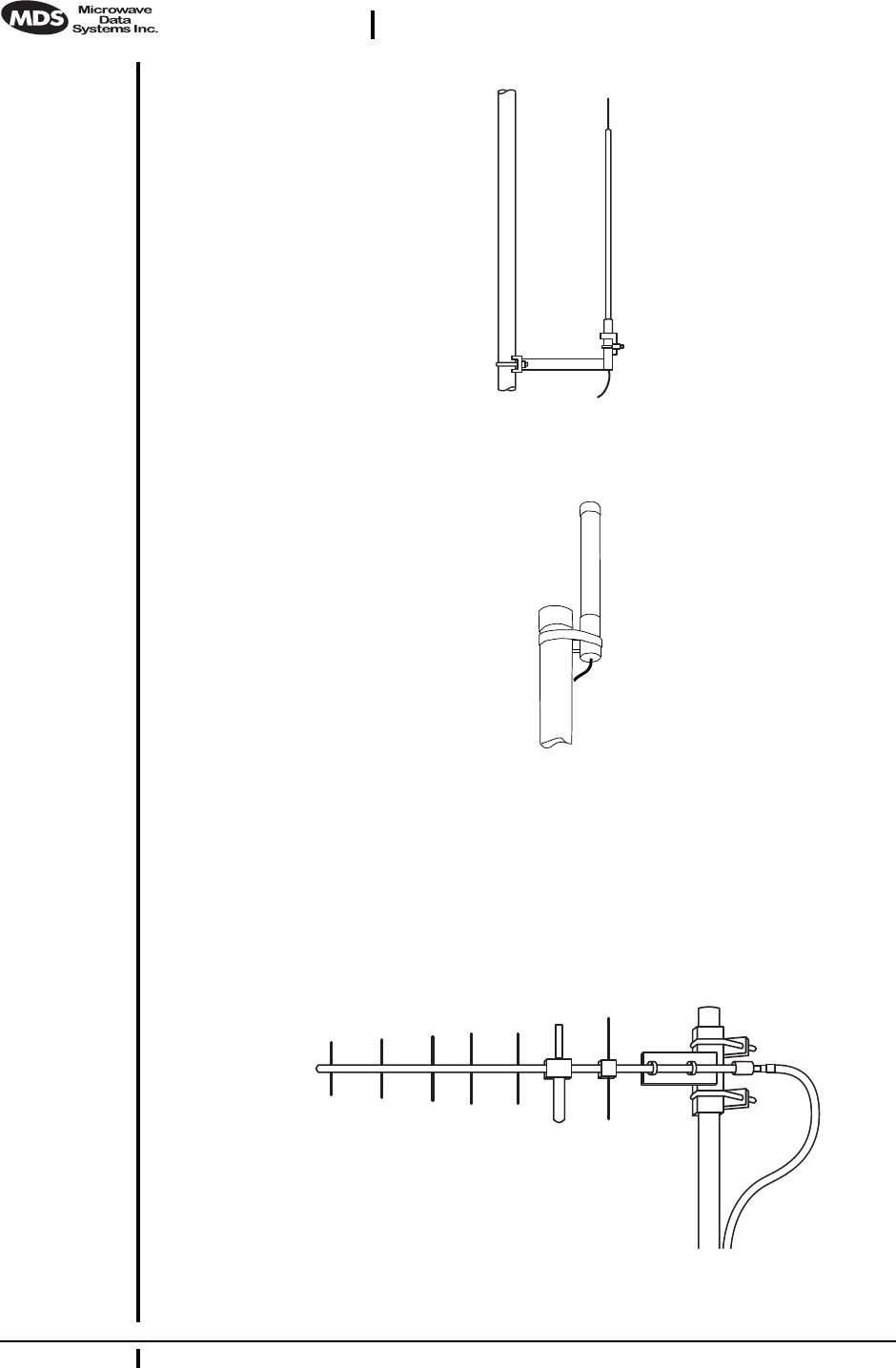
In general, an omnidirectional antenna (Figure 5) is used at the Access
Point station site. This provides equal coverage to all of the Station
Adapter sites.
NOTE: Antenna polarization is important. If the wrong polarization is
used, a signal reduction of 20 dB or more will result. Most
systems using a gain-type omnidirectional antenna at the
Access Point station employ vertical polarization of the signal;
therefore, the remote antenna(s) must also be vertically polar-
ized (elements oriented perpendicular to the horizon).
When required, horizontally polarized omnidirectional
antennas are also available. Contact your MDS representative
for details.
10 MDS iNet 900 Installation Guide MDS 05-2873A01, Rev. A
DRAFT 6—8/29/01
Invisible place holder
Figure 5. Omnidirectional antenna for iNet 900 transceiver
Invisible place holder
Figure 6. Omnidirectional antenna for
iNet 900 transceiver (mounted to mast)
At Station Adapter sites and units in point-to-point LANs, a directional
Yagi (Figure 7) antenna is generally recommended to minimize interfer-
ence to and from other users. Antennas are available from a number of
manufacturers.
Invisible place holder
Figure 7. Typical Yagi antenna (mounted to mast)

MDS 05-2873A01, Rev. A MDS iNet 900 Installation and Operation Guide 11
DRAFT 6—8/29/01
Feedlines
The choice of feedline used with the antenna should be carefully consid-
ered. Poor-quality coaxial cables should be avoided, as they will
degrade system performance for both transmission and reception. The
cable should be kept as short as possible to minimize signal loss.
For cable runs of less than 20 feet (6 meters), or for short range trans-
mission, an inexpensive type such as Type RG8A/U may be acceptable.
Otherwise, we recommend using a low-loss cable type suited for 900
MHz, such as Heliax®.
Table 3 lists several types of popular feedlines and indicates the signal
losses (in dB) that result when using various lengths of cable at
900 MHz. The choice of cable will depend on the required length, cost
considerations, and the amount of signal loss that can be tolerated.
3.5 How Much Output Power Can be Used?
The transceiver is normally supplied from the factory set for a nominal
+30 dBm (1 Watt) RF power output setting; this is the maximum trans-
mitter output power allowed under FCC rules. The power must be
decreased from this level if the antenna system gain exceeds 6 dBi. The
allowable level is dependent on the antenna gain, feedline loss, and the
transmitter output power setting. Power considerations for point-to-mul-
tipoint and point-to-point systems using the iNet 900 transceivers are
discussed in the next sections.
NOTE: In some countries, the maximum allowable RF output may be
limited to less than 1 watt (For example, 100 mW /+20 dBm).
Be sure to check for and comply with the requirements for
your area.
Table 3. Length vs. loss in coaxial cables at 900 MHz
Cable Type 10 Feet
(3.05
Meters)
50 Feet
(15.24
Meters)
100 Feet
(30.48
Meters)
500 Feet
(152.4
Meters)
RG-8A/U 0.85 dB 4.27 dB 8.54 dB 42.70 dB
1/2 inch HELIAX 0.23 dB 1.15 dB 2.29 dB 11.45 dB
7/8 inch HELIAX 0.13 dB 0.64 dB 1.28 dB 6.40 dB
1-1/4 inch HELIAX 0.10 dB 0.48 dB 0.95 dB 4.75 dB
1-5/8 inch HELIAX 0.08 dB 0.40 dB 0.80 dB 4.00 dB

12 MDS iNet 900 Installation Guide MDS 05-2873A01, Rev. A
DRAFT 6—8/29/01
Calculating System Gain
To determine the maximum allowable power setting of the radio, per-
form the following steps:
1. Determine the antenna system gain by subtracting the feedline loss
(in dB) from the antenna gain (in dBi). For example, if the antenna
gain is 9.5 dBi, and the feedline loss is 1.5 dB, the antenna system
gain would be 8 dB. (If the antenna system gain is 6 dB or less, no
power adjustment is required.)
2. Subtract the antenna system gain from 36 dBm (the maximum
allowable EIRP). The result indicates the maximum transmitter
power (in dBm) allowed under the rules. In the example above, this
is 28 dBm.
3. If the maximum transmitter power allowed is less than 30 dBm, use
one of the transceiver’s control tools as described in PROGRAM-
MING on page 21 to set the power accordingly.
For convenience, Table 4 lists several antenna system gains and shows
the maximum allowable power setting of the radio. Note that a gain of 6
dB or less entitles you to operate the radio at full power output—30 dBm
(1 watt).
* Most antenna manufacturers rate antenna gain in dBd in their
literature. To convert to dBi, add 2.15 dB.
† Feedline loss varies by cable type and length. To determine the
loss for common lengths of feedline, see Table 3 on page 11.
For details on how to set the power level via the Ethernet/HTTP inter-
face, See “Programming Via an HTTP/Web Browser” on page 22 for
details.
Table 4. Antenna system gain vs. power output setting (USA)
Antenna System Gain
(Antenna Gain in dBi*
minus Feedline Loss in dB†)
Maximum Power
Setting
(in dBm) EIRP
(in dBm)
6 (or less) 30 36
82836
10 26 36
12 24 36
14 22 36
16 20 36

MDS 05-2873A01, Rev. A MDS iNet 900 Installation and Operation Guide 13
DRAFT 6—8/29/01
4.0 INSTALLATION
A typical transceiver product shipment consists of an iNet 900 trans-
ceiver and a manual. Check the contents against the packing list secured
to the outside of the shipping box. Accessories and spare parts kits, if
any, are wrapped separately. Inspect all items for signs of damage and
save all packing materials for possible re-shipment.
Below are the basic steps for installing a iNet 900 transceiver. In most
cases, these steps alone will be sufficient to complete the installation.
Should further information be required, contact the factory at the
number given on the inside back cover of this manual.
If you are installing a traditional repeater system, you should also see
“TRADITIONAL REPEATER CONFIGURATION WITH TWO
RADIOS” on page 20 for important details on antennas and cabling.
NOTE: It is recommended that the Access Point station be installed
first. In this way, it will be possible to quickly check the oper-
ation of each associated Station Adapter unit as it is placed on
the air.
MDS iNet 900 transceivers are shipped from the factory set
to the “Station Adapter” mode unless they are marked
differently.
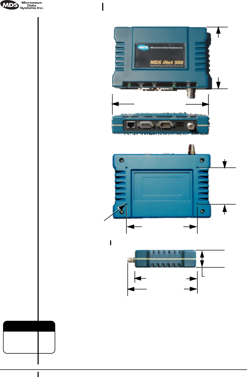
4.1 Step 1— Mounting the Transceiver
Mount the transceiver to a stable surface. (Fasteners/anchors are not
supplied unless specified when the order.) Figure 8 shows the dimen-
sions of the transceiver case and its mounting bracket. If possible,
choose a mounting location that provides easy access to the connectors
on the end of the radio and an unobstructed view of the LED status indi-
cators. Four threaded holes are located on the bottom of the radio which
are suitable for connecting mounting hardware. Use 6-32 x 1/4 inch
screws to attach mounting hardware to the bottom of the radio. (See
Figure 8 on page 14 for dimensions.)
14 MDS iNet 900 Installation Guide MDS 05-2873A01, Rev. A
DRAFT 6—8/29/01
Invisible place holder
Figure 8. Transceiver dimensions
The screws holding the brackets to the radio are 5⁄16 inch (8 mm) long
or shorter to prevent damage to the radio’s PC board when they are
tightened. If these screws are replaced for any reason, the new screws
must not exceed this length. The radio’s case is made of a durable
cast-aluminum, however, the use of the wrong sized screws can dam-
age the screw sockets on the cover.
4.25˝ (10.8 cm)
4.75˝ (12 cm)
1.25˝ (3.17 cm)
6.75˝ (17.15 cm)
4.5˝ (11.4 cm)
TOP
FRONT
SIDE
BOTTOM
2.5˝ (6.35 cm)
4.85˝ (12/3 cm)
THREADED HOLES
FOR MOUNTING
SCREWS (4)
#6-32 X 1/4˝
CAUTION
POSSIBLE
EQUIPMENT
DAMAGE

MDS 05-2873A01, Rev. A MDS iNet 900 Installation and Operation Guide 15
DRAFT 6—8/29/01
4.2 Step 2—Install the Antenna and Feedline
Antennas should be mounted in the clear and in accordance with the
manufacturer’s instructions. Additional information on antennas and
feedlines is contained in Section 3.4 (page 9).
NOTE: Strong fields near the antenna can interfere with the operation
of the low-level RTU circuits and change the reported values
of the data being monitored. For this reason, the antenna
should be mounted at least 10 feet (>3 meters) from the radio,
RTU, sensors and other components of the system.
4.3 Step 3—Connect the Data Equipment
Connect the data equipment to one of the transceiver’s three ports: LAN,
COM1 or COM2. Use only the required pins for the application—do not
connect anything to unused pins. See Figure 19 on page 33 details on
COM1 Port and Figure 20 on page 34 for the COM2 Port. Figure 9 on
page 16 identifies the port’s factory defaults.
NOTE: The data cabling between the transceiver and the connected
device should be kept as short as possible. Cable runs over 50
feet (15 meters) may require the use of a EIA-422 signaling
adapter. Consult the factory for further information.
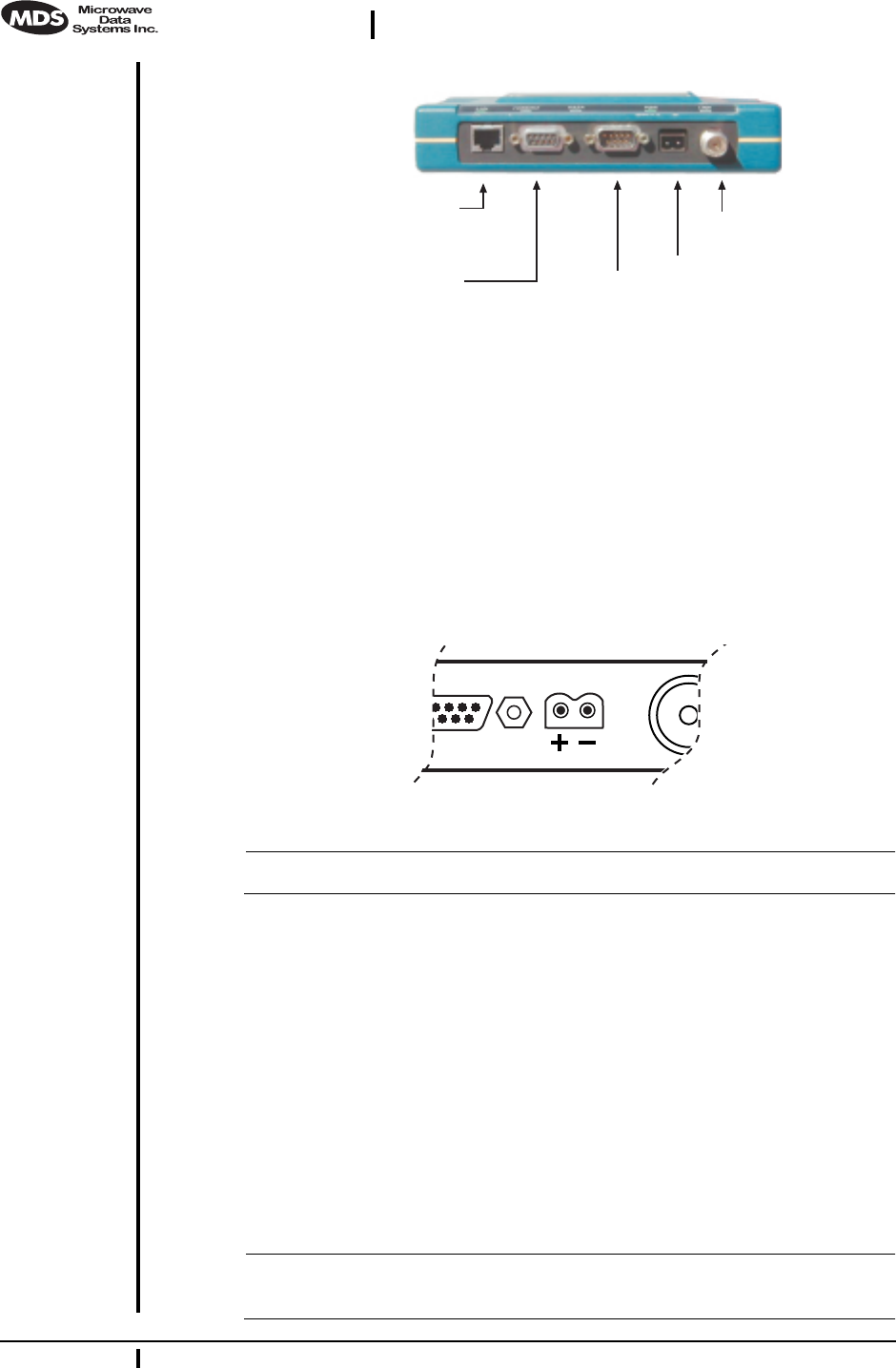
Configuration
Toolbox Access Figure 9 on page 16 shows the default functions and services for the
front panel interface connectors. The three data ports—LAN, COM1 and
COM2—are user configurable through the use of a terminal connected to
the COM1 port or a HTTP browser through the Ethernet port.
NOTE: The data communications parameters and functions described
in the installation procedures and shown in Figure 9 on
page 16 are based on factory defaults. If the COM1 Port is
configured to transport data, connect to it with a terminal
program and use the ESC + K sequence to reset the radio’s data
interface ports to the default settings.
Connect a terminal to COM1 to access the menu driven configuration
and control tool. The menu will automatically display on the terminal’s
screen. To use a HTTP browser, connect to the Ethernet port and type in
HTTP:// + unit IP address. The unit’s IP address can be found through the
use of a terminal connected to the COM1 port.
16 MDS iNet 900 Installation Guide MDS 05-2873A01, Rev. A
DRAFT 6—8/29/01
Invisible place holder
Figure 9. MDS iNet Interface Default Configuration & Functions
4.4 Step 4—Measure & Install Primary Power
The primary power at the transceiver’s power connector must be within
10.5–30 Vdc and be capable of furnishing up to 500 mA. The optimum
voltage is 12 Vdc. Be sure to observe proper polarity as shown in
Figure 10.
Invisible place holder
Figure 10. Primary Power (DC) Polarity
NOTE: The radio is designed for use only in negative ground systems.
The power supply used with the transceiver should be equipped with
overload protection (NEC Class 2 rating), to protect against a short cir-
cuit between its output terminals and the transceiver power connector.
4.5 Step 5—Review the Radio’s Configuration
There are two essential settings for iNet 900 transceivers that should be
known before placing the radio into service. They are:
Radio Operating Mode—Access Point or Station Adaptor
Network Name—Unique name of the radio network used to
generate the hopping pattern.
NOTE: Transceivers are normally shipped from the factory
pre-configured as remotes.
COM2
◆ DTE Serial Data Equip.
◆ 9600 bps/8N1
◆ Full Handshaking
◆ Connect Legacy Equip.
LAN
◆ 10BaseT
◆ IP/Ethernet Port
◆Connect IP Data Equip.
COM1
◆DCE Console/Terminal
◆ 115,200 bps/8N1
◆No Handshaking
PRIMARY POWER
◆ 13.8 Vdc @ 500 ma
(10.5–30 Vdc)
◆ Negative Ground
◆ +/Left –/Right
ANTENNA
◆ 50Ω TNC

MDS 05-2873A01, Rev. A MDS iNet 900 Installation and Operation Guide 17
DRAFT 6—8/29/01
There are additional settings for iNet 900 transceivers that may need
changing before placing the radio into service. They are:
Unit IP Address—Must be a unique number to allow for IP
access through the Ethernet Port.
Transmitter Power Output Level—Default is 1 Watt. Adjust
as necessary for compliance with FCC guidelines.
NOTE: The IP address is important if the radio’s LAN (Ethernet) port
will be used for IP-based data communications or for unit
configuration.
The following procedures are summaries only. For more detailed
instructions on using the menu-based COM1 and the HTTP/Bowser
interfaces, see See “PROGRAMMING” on page 21.
Procedure
With Terminal
Program a. Connect a personal computer’s serial communications port
(COM1 or COM2) to the COM1 Port connector on the radio
transceiver. (See Figure 9 on page 16 for location. Data defaults:
115,200 kpbs/8N1.)
b. Launch a terminal emulator program, such as Hyperterminal, on
the computer.
c. Depress the ENTER key. The radio will respond with the start-up
screen of a text-based Management Toolbox.
d. Select the desired options to review existing settings and to ini-
tiate necessary changes such as the IP address and other network
parameters.
A login with password will be required to make any changes to
the radio. (Default password= admin)
e. Record the unit Mode, IP Address and Network Name settings
on a label and place it on the transceiver’s cover
f. Exit the set-up tool.
g. Repeat the above steps for each transceiver in the network.
With HTTP Browser a. Connect a personal computer’s Ethernet port to the EHTERNET
Port connector on the radio transceiver. (See Figure 9 on page 16
for location.)

18 MDS iNet 900 Installation Guide MDS 05-2873A01, Rev. A
DRAFT 6—8/29/01
NOTE: It may be necessary to change your IP access to the local area
network on which the MDS iNet 900 radio is attached. The
radio’s IP address should be listed on the unit’s packaging slip.
If it is not, you can find it out using the preceding procedure to
communicate with the radio through the COM1 Port.
a. Launch a Web-browser (HTTP) program, such as Internet
Explorer™, on the computer.
b. Type in “HTTP://” followed by the radio’s IP address. For exam-
ple “http://192.168.1.1/”. 1Z? (Default = 192.168.1.1)
c. The Management Toolbox startup screen will appear.
d. Select the desired options to review existing settings and to ini-
tiate necessary changes such as the IP address and other network
parameters.
A login with password will be required to make any changes to
the radio. (Default password= admin)
e. Record the unit Mode, IP Address and Network Name settings
on a label and place it on the transceiver’s cover.
f. Exit the Management Toolbox.
g. Repeat the above steps for each transceiver in the network.
4.6 Step 6—Connect the User Data Equipment
If the radio network seems to be operating properly based on observa-
tion of the unit’s LEDs, connect the user equipment to one of the data
ports. Use the IP PING command to verify the link integrity with the
Access Point unit.
4.7 Step 7—Check for Normal Operation
Procedure
a. Apply primary power to the radio.
1. The address 127.0.0.1 has also been suggested as the default. Which is cor-
rect?

MDS 05-2873A01, Rev. A MDS iNet 900 Installation and Operation Guide 19
DRAFT 6—8/29/01
b. Observe the transceiver LED status panel (Table 2 on page 7) for
the proper indications. In a normally operating system, the fol-
lowing LED indications will be seen within a few seconds of
start-up:
•PWR lamp lit continuously
•LINK lamp blink intermittently
If the LINK LED is not on, check the received signal strength indi-
cator for an adequate signal level from the radio network’s Access
Point station. It may be necessary to reposition the radio’s antenna
for better reception/signal strength, or if a directional antenna is
used, rotate it until the signal is optimized.
In-service operation of the MDS iNet 900 transceiver is completely
automatic. Once the unit has been properly installed and config-
ured, operator actions are limited to observing the LED status indi-
cators for proper operation. See Table 2 on page 7 for details on the
LED functions.
4.8 Performance Optimization
After the basic operation of the radio has been checked, you may wish
to optimize its performance using some of the suggestions given here.
The effectiveness of these techniques will vary with the design of your
system and the format of the data being sent.
Complete instructions on using the unit’s configuration options refer-
enced within this section are can be found in Section 6.0, PROGRAM-
MING (beginning on page 21).
Antenna Aiming
For optimum performance of directional antennas, they must be accu-
rately aimed in the direction of desired transmission. The easiest way to
do this is to point the antenna in the approximate direction, then use the
remote radio’s built-in Received Signal Strength Indication (RSSI) fea-
ture to further refine the heading for maximum received signal strength.
RSSI can be read by connecting a terminal (COM1 Port) or Internet
browser (LAN Port) to the iNet 900 radio and requesting the RSSI reports.
In an iNet 900 system, RSSI readings are only meaningful when initi-
ated from a Station Adaptor. This is because the Access Point station
typically receives signals from several remote sites, and the RSSI would
be continually changing as the Access Point receives from each remote
in turn.

20 MDS iNet 900 Installation Guide MDS 05-2873A01, Rev. A
DRAFT 6—8/29/01
Antenna SWR Check (Z? Major revision needed?)
It is necessary to briefly key the transmitter1Z? for this check by placing
the radio in the SETUP mode (page 42) and using the KEY command on
the HHT. (To unkey the radio, enter DKEY; to disable the setup mode and
return the radio to normal operation, enter Q or QUIT.)
The SWR of the antenna system should be checked before the radio is
put into regular service. For accurate readings, a wattmeter suited for
1000 MHz is required. One unit meeting this criteria is the Bird Model
43™ directional wattmeter with an 5J element installed.
The reflected power should be less than 10% of the forward power (≈2:1
SWR). Higher readings usually indicate problems with the antenna,
feedline or coaxial connectors.
If the reflected power is more than 10%, check the feedline, antenna and
its connectors for damage.
5.0 TRADITIONAL REPEATER
CONFIGURATION WITH TWO
RADIOS
5.1 Overview
Two MDS iNet 900 radios may be connected “back-to-back” through
the LAN Ports to form a repeater station. (The cable must be a
“cross-over” Ethernet cable for this to work). This configuration is
sometimes required in a network that includes a distant Station Adaptor
that would otherwise be unable to communicate directly with the Access
Point station due to distance or terrain.
A repeater works by re-transmitting data from the outlying remote site
to the Access Point station and vice versa. It introduces a small amount
of end-to-end transmission delay, but this is not a problem in most sys-
tems.
The geographic location of a repeater station is especially important. A
site must be chosen that allows good communication with both the
Access Point and the outlying remote site. This is often on top of a hill,
or other elevated terrain from which both sites can be “seen” by the
repeater station antennas. A detailed discussion on the effects of terrain
is given in Section 3.2, Site Selection (beginning on page 6).
The following paragraphs contain specific requirements for repeater
systems.
1. Is it true that we still need to key the transmitter to use the RSSI function to
aim the antenna?
MDS 05-2873A01, Rev. A MDS iNet 900 Installation and Operation Guide 21
DRAFT 6—8/29/01
5.2 Antennas
Two antennas are required at repeater stations—one for each radio.
Measures must be taken to minimize the chance of interference between
these antennas. One effective technique for limiting interference is to
employ vertical separation. In this arrangement, one antenna is
mounted directly over the other, separated by at least 10 feet (3 Meters).
This takes advantage of the minimal radiation exhibited by most
antennas directly above and below their driven elements.
Another interference reduction technique is to cross-polarize the
repeater antennas. If one antenna is mounted in the vertical plane, and
the other in the horizontal plane, an additional 20 dB of attenuation can
be achieved. (Remember that the corresponding stations must use the
same antenna orientation when cross-polarization is used.)
5.3 Network Name
The two radios that are wired together at the repeater site must have dif-
ferent network names. To set or view the network names, see “PRO-
GRAMMING” on page 21 and Table 5 on page 26 for details.
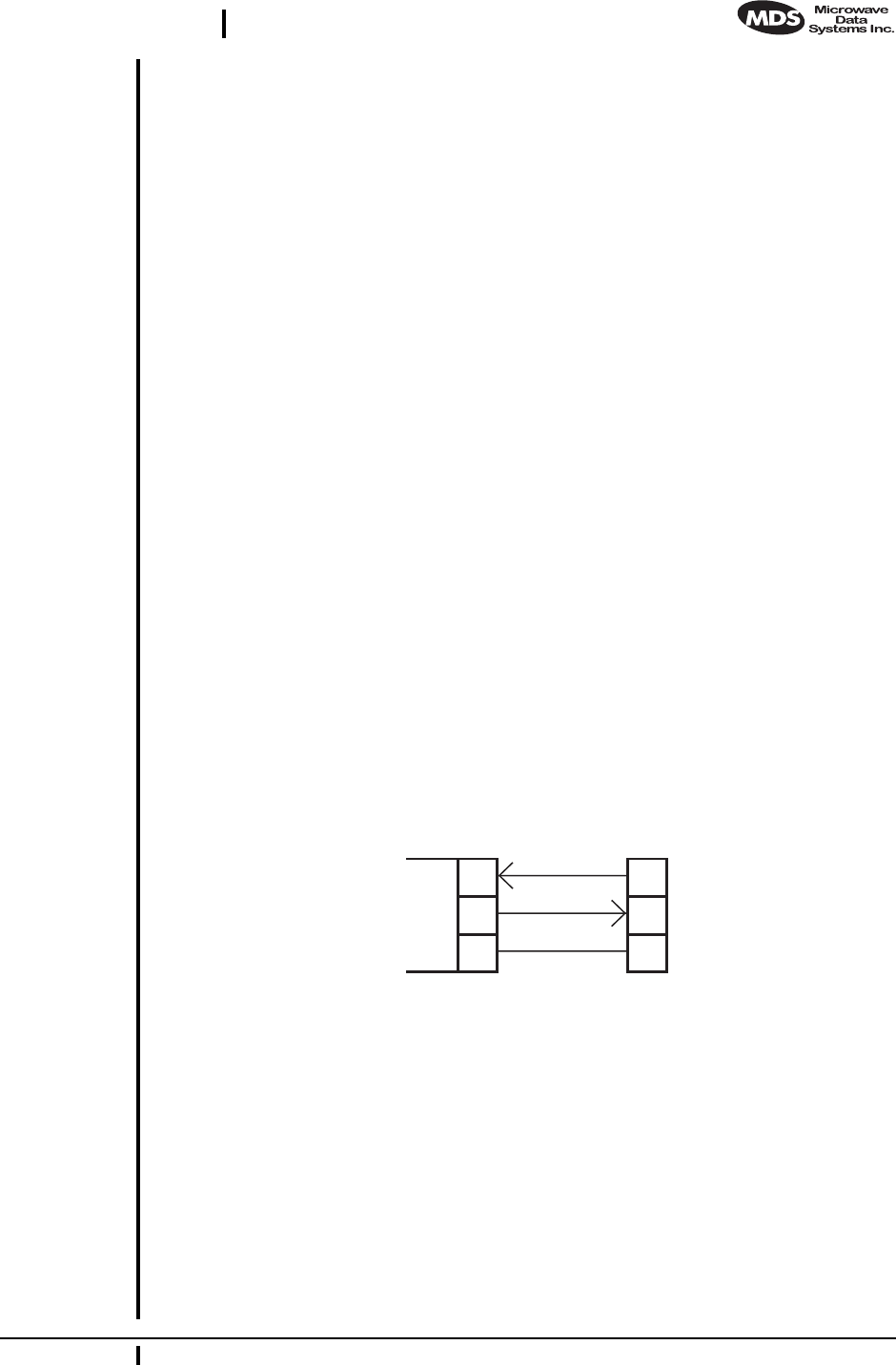
5.4 Interface Wiring
A null-modem cable (Figure 11) is required between the COM1 port con-
nectors of the two radios forming a repeater station. This allows them to
freely exchange data even though they are both configured as DCE
devices.
Invisible place holder
Figure 11. Data interface cable wiring for null-modem cable
(used for traditional repeater)
6.0 PROGRAMMING
There are no manual adjustments on the transceiver. Programming and
control is performed remotely, using one of these methods:
• HTTP (Browser) via the iNet 900’s ETHERNET Port
DB-25 DB-25
Spread Spectrum
Master
(DCE)
2
3
7
3
2
7
Spread Spectrum
Remote
(DCE)
TXD
RXD
GND
RXD
TXD
GND
Z? REVISON NEED TO DB-9 CONNECTORS
22 MDS iNet 900 Installation Guide MDS 05-2873A01, Rev. A
DRAFT 6—8/29/01
• Telenet via the iNet 900’s ETHERNET Port (To Be Developed)
• ASCII Terminal or emulator via the COM1 Port
This section needs further development. The only items that com-
monly need changes are the unit’s network name, IP address, power
level and system mode—Access Point or Station Adapter.
6.1 Programming Via an HTTP/Web Browser
A wide range of configuration, control and diagnostic tools are available
through a Web browser communicating with the radio via the Internet
Protocol (IP). The following is a brief overview of the HTTP interface
and several key configuration parameters since detailed help is available
on-line.
Making the Connection
Connect a personal computer’s Ethernet port to the EHTERNET Port con-
nector on the radio transceiver. (See Figure 9 on page 16 for location.)
NOTE: It may be necessary to change your IP access to the local area
network on which the MDS iNet 900 radio is attached. The
radio’s IP address should be listed on the unit’s packaging slip.
If it is not, you can find it out using the preceding procedure to
communicate with the radio through the COM1 Port.
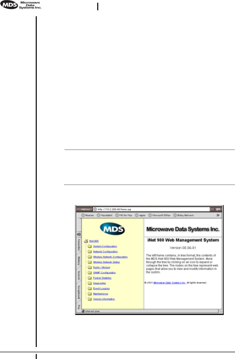
Start-up Screen
Invisible place holder
Figure 12. MDS iNet Web Management System Start-up Screen
The startup screen is the gateway to many radio performance monitoring
and configuration functions. Interact with it as you would any Web site.
MDS 05-2873A01, Rev. A MDS iNet 900 Installation and Operation Guide 23
DRAFT 6—8/29/01
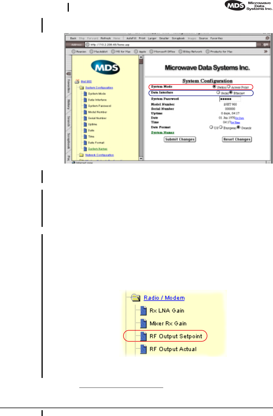
System Configuration Screen Invisible place holder
Figure 13. System Configuration Screen
(Items discussed are outlined with red and blue.)
System Mode This screen is the location where you will check and set, if necessary,
the “System Mode”. If the unit will serve as the Access Point station and
Access Point (gateway) into the IP network, click on Access Point. There
should only be one radio in each iNet network set to Access Point. All
other radios in the system should be set to Station.
Data Interface Here too is the location for choosing the primary data port for the radio.
By default, it is the ETHERNET Port. If you are connecting lower speed,
RS/EIA-232 devices, click on the Serial Port button, and then the Submit
button to implement the change.
Radio/Modem Screen 1Z? Invisible place holder
Figure 14. Radio/Modem Menu Items
(Item discussed are outlined with red.)
1. This direction is a guess as the setting controls are not active on my prototype.

24 MDS iNet 900 Installation Guide MDS 05-2873A01, Rev. A
DRAFT 6—8/29/01
RF Power Output This screen is the location where you will check and set, if necessary,
the radio’s RF power output. The default is one Watt. If you need to
lower the power, click on the RF Output Setpoint menu item, type in the
desired power level in dBm on the right-hand portion of the screen and
then click the Submit button to implement the change.
See Table 5, “. Common Transceiver Parameters,” on page 26 for a list
of common configuration parameters and their defaults.
6.2 Programming Via COM1 Port & a Terminal
Program
A serial-interface based Management Toolbox is available for local con-
figuration of the MDS iNet 900 transceiver.
Making the Connection
Connect a personal computer’s communication port to the transceiver’s
COM1 Port connector on the radio transceiver. (See Figure 9 on page 16
for location.) The default interface is EIA-232 at 115,200 bps with 8N1.
Initializing the Connection
On you Windows’ PC, launch a terminal program, such as MS Win-
dows’ Hyperterminal™, and select the serial port connected to the
COM1 Port of the transceiver. The default interface is EIA-232 at
115,200 bps with 8N1.
Communicating with the iNet transceiver
The transceiver’s port will automatically display the text-based Man-
agement Toolbox start-up screen as seen in Figure 15 on page 25 one the
ENTER key is pressed.
NOTE: If the terminal program is running and your computer
connected to the transceiver, you may see a series of pages of
text information relating to the booting of the unit’s microcom-
puter. Disregard this information and wait a few seconds for
the display to stabilize before proceeding.
Using the Menu-Based Management Toolbox
The menu-based Management Toolbox provides access to view and
configure many unit parameters and provides you with basic diagnostic
tools.
MDS 05-2873A01, Rev. A MDS iNet 900 Installation and Operation Guide 25
DRAFT 6—8/29/01
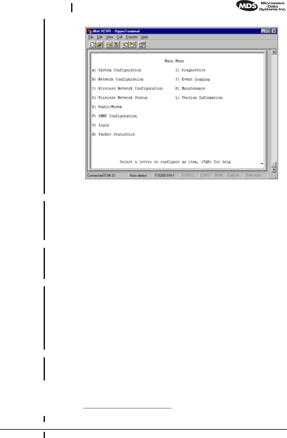
Invisible place holder
Figure 15. Management Toolbox Start-up Screen
Navigation From the Main Menu you navigate by pressing the key to the left of the
offering. You will then be taken to a screen associated with that func-
tion. If you select a menu item that is not user-configurable, the message
“Note: This is not a configurable item.” Pressing the ESCAPE
key will navigate you to the previous menu or level.
Help Pressing F1 from any menu will place the Management Toolbox in the
Help mode; pressing the key corresponding to the menu item will pro-
vide you with useful information or instructions. Pressing the ESCAPE
key will exit the Help Mode and return you to the previous screen.
Logging In and
Password All screens are accessible to any user. To change a user-controllable
parameter, you must log into the system and enter a password. The
default user password is “admin” in lowercase letters. The main menu
item will change from Login to Logout. The user will automatically be
logged out after 10 minutes of inactivity.1Z?
If you know that you want in advance to change one or more parameter,
you should log in from the Main Menu.
Logging Out Once you are logged in, you can go to the System Configuration Menu and
change the password (case-sensitive). Follow any changes to the pass-
word or other parameters with an ENTER key to save the change.
1. This is a guess. Please verify value and function

26 MDS iNet 900 Installation Guide MDS 05-2873A01, Rev. A
DRAFT 6—8/29/01
Review and Changing Essential Parameters
Through the Main Menu you can access other screen to review and change
several commonly altered parameters. The table below will provide you
with a summary of the location and parameter’s range of values.
7.0 TROUBLESHOOTING
Successful troubleshooting of an MDS transceiver system is not diffi-
cult, but requires a logical approach. It is best to begin troubleshooting
at the Access Point station, as the rest of the system depends on the
Access Point for polling instructions and synchronization data. If the
Access Point station has problems, the operation of the entire network
will be affected.
When communication problems are found, it is good practice to begin
by checking the simple things. All radios in the network must meet these
basic requirements:
• Adequate and stable primary power
• An efficient and properly aligned antenna system
• Secure connections (RF, data & power)
• Proper programming of the radio’s operating parameters, espe-
cially Mode selection (Access Point/Remote) and IP Network
Address
• The correct interface between the radio and the connected data
equipment (proper cable wiring, data format and timing).
Table 5. Common Transceiver Parameters1
Item Screen Values Default
System Mode System
Configuration Station Adapter
Access Point
Station Adapter
System Password System
Configuration 1–8 alphanumeric
characters. May be mixed
case.
CAUTION: Login is case
sensitive.
admin
(lower case)
Data Interface System
Configuration • Ethernet
• EIA/RS-232
Ethernet
Network Name Wireless
Network
Configuration
1–16 alphanumeric
characters. May be mixed
case.
mds-wlan
(lower case)
IP Address Network
Configuration
Menu
Contact your network
administrator 192.168.1.12Z?
Power Output Radio/Mode
m20–30 dBm
(0.1–1.0 Watts) 30 dBm
(1.0 Watt)
1. All parameters are protected by password. You must be logged in to make
any changes.
2. I was told 127.0.0.1 by Aaron Wright. Which is correct?

MDS 05-2873A01, Rev. A MDS iNet 900 Installation and Operation Guide 27
DRAFT 6—8/29/01
7.1 LED Indicators
The LED status indicators are an important troubleshooting tool and
should be checked whenever a problem is suspected. Table 2 on page 7
describes the function of each status LED.
7.2 Troubleshooting Chart
Table 6 provides suggestions for resolving system difficulties that may
be experienced in the radio system. If problems persist, contact the fac-
tory for further assistance. Refer to the inside back cover of this guide
for contact information.
Table 6. Troubleshooting Techniques
Difficulty Recommended System Checks
Unit is
inoperative. a. Check for the proper supply voltage at the power
connector.
b. The transceiver’s internal resettable fuse may have tripped.
To reset it, momentarily remove and re-apply power to the
radio.
Interference is
suspected. a. Verify that the system has a unique network name. Nearby
systems with the same network name will cause
interference.
b. If omnidirectional antennas are used on Station Adaptors,
consider changing to directional antennas. This will often
limit interference to and from other stations.
No synchronization
with Access Point,
or poor overall
performance.
a. Check for secure interface connections at the radio and the
connected device.
b. Check the antenna, feedline and connectors. Reflected
power should be less than 10% of the forward power
reading (SWR ≈2:1 or lower).
28 MDS iNet 900 Installation Guide MDS 05-2873A01, Rev. A
DRAFT 6—8/29/01
8.0 REPEATER ASSITED LANS
Repeater Systems
A repeater works by re-transmitting data from the outlying remote site
to the Access Point station and vice-versa. It introduces a small amount
of end-to-end transmission delay, but this is not a problem in most sys-
tems.
The geographic location of a repeater station is especially important. A
site must be chosen that allows good communication with both the
Access Point and the outlying remote site. This is often on top of a hill,
or other elevated terrain from which both sites can be “seen” by the
repeater station antennas. A detailed discussion on the effects of terrain
is given in Section 3.2, Site Selection (beginning on page 6).
The following paragraphs contain specific requirements for repeater
systems.
Option 1—Traditional with two-radio repeater 1Z?
Although the range between iNet LANS is up to 50 miles over average
terrain, it is possible to extend the range considerably by connecting two
units together at one site in a “back-to-back” fashion to form a repeater,
as shown in Figure 16.
Invisible place holder
Figure 16. Typical LAN with dual-transceiver repeater
For more detailed information on this configuration, see “TRADI-
TIONAL REPEATER CONFIGURATION WITH TWO RADIOS” on
page 20
1. What are the advantages and/or limitations of each of these two repeater con-
figurations?
iNet S.A.
iNet A.P. iNet S.A.
iNet S.A.
iNet S.A.
iNet S.A.
RTU
HOST
COMPUTER
RTU
RTU
REPEATER
LINK
Cross-Over
Cable
POINT-TO-POINT LINK
MDS 05-2873A01, Rev. A MDS iNet 900 Installation and Operation Guide 29
DRAFT 6—8/29/01
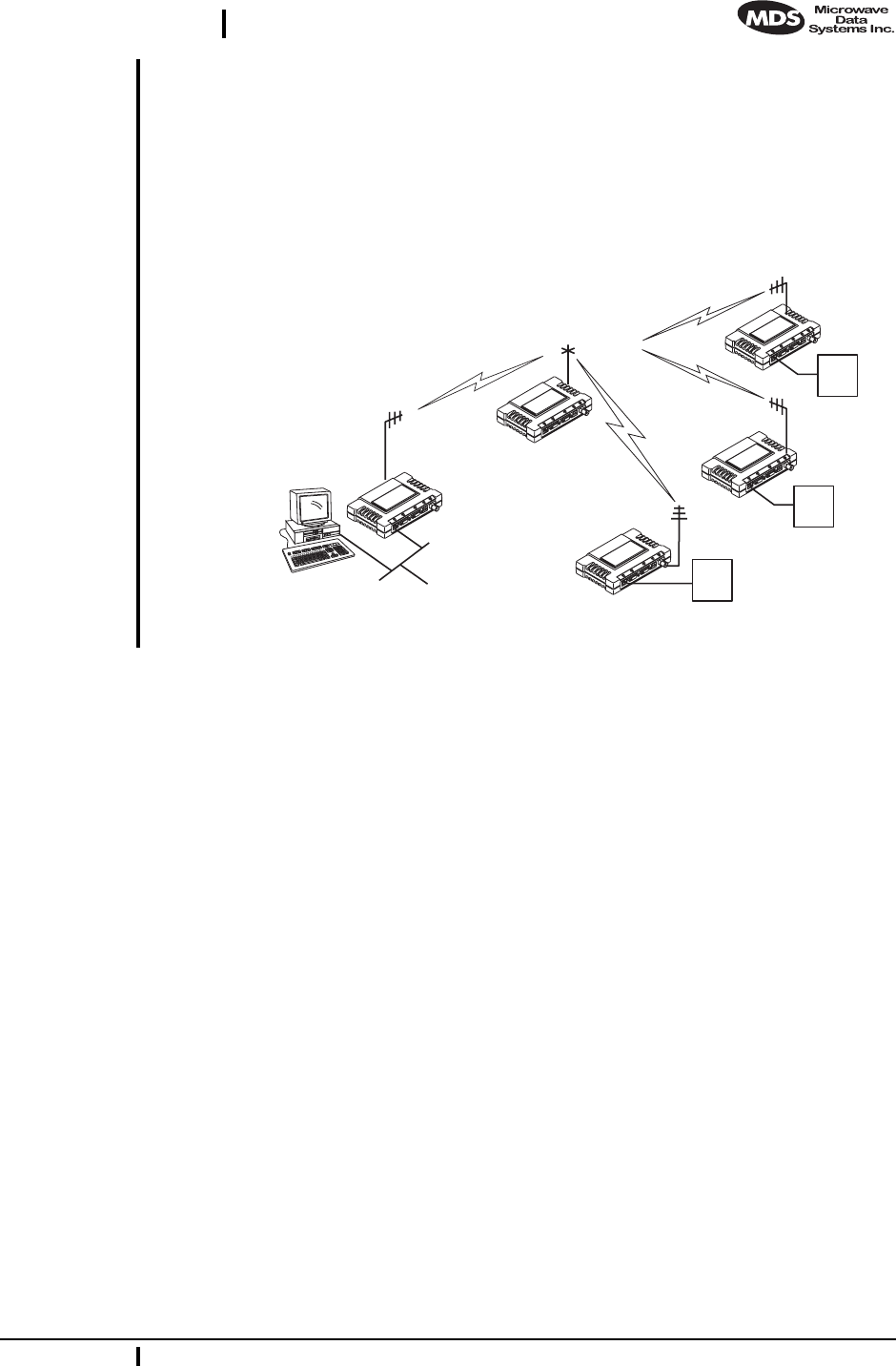
Option 2—With Store-and-Forward Station
A LAN can be extended through the use of an alternate arrangement (see
Figure 17). This second arrangement overcomes the limitations of ter-
rain by using a single-unit repeater to re-transmit the signals of all sta-
tions in the network. The repeater is a standard MDS iNet 900 radio
configured as an Access Point with data store-and-foreword.
Invisible place holder
Figure 17. Typical network with store-and-forward repeater
iNet A.P.
iNet S.A.
iNet S.A.
iNet S.A.
iNet S.A.
RTU
HOST
COMPUTER
RTU
RTU
STORE-AND-FORWARD

30 MDS iNet 900 Installation Guide MDS 05-2873A01, Rev. A
DRAFT 6—8/29/01
9.0 TECHNICAL REFERENCE
The following section contains material that is not essential to using the
radio, but may prove helpful in diagnosing performance problems or in
gaining a better understanding of the unit’s operation.
9.1 Technical Specifications
GENERAL
Temperature Range: –30°C to +70°C (–22° F to 158° F)
Humidity: 95% at +40°C (104° F); non-condensing
Primary Power: 10.5–30 Vdc(13.8 Vdc Nominal)
External Power Supply Options: 48 Vdc; 110–120/210–220 Vac
Supply Current (typical): (@ 1 Watt RF Output)
Transmit: 500 mA @ 13.8 Vdc
Receive: < 125 mA @ 13.8 Vdc
Doze Mode: < 30 mA @ 13.8 Vdc
Size (Excluding mtg. hardware): 1.5" x 6" x 4" (H x W x D)
3.8 x 15.2 x 10.2 cm
Mounting w/Optional Hardware: • Flat surface mounting brackets
• DIN rail
• 19” rack (1U high)
Weight: 0.9 kg / 2 lb
Case: Cast Aluminum
Shock and Vibration: MIL STD 202F, 810E, 202D
APPROVALS/HOMOLOGATION (PLANNED)
• FCC Part 15.247
• Industry Canada RSS-210 and RSS-139
• UL/FM Class 1, Div. 2; Groups A, B, C and D
hazardous locations
• UL Listed
• CE Mark
• Contact MDS for information on availability and
governmental approvals in other countries
UNIT & NETWORK MANAGEMENT
• HTTP (Embedded Web server)
• SNMPv1, MIB II, Enterprise MIB
• Text-based menu on COM1 serial port
• Telnet

MDS 05-2873A01, Rev. A MDS iNet 900 Installation and Operation Guide 31
DRAFT 6—8/29/01
DATA CHARACTERISTICS
PORTS:
Ethernet:
Interface Connectors: RJ-45 Standard
Data Rate: 10-BaseT
Serial (2):
Signaling Standard: EIA-232/V.24
Interface Connectors: DB-9 female
Interface: COM1: DCE / COM2: DTE/DCE
Data Rate: 1200–115,200 bps
asynchronous
Data Latency: <10 ms typical
Byte Length: 10 or 11 bits
OPERATING MODES: • Configurable as Access Point or Station LAN
Adapter
• CSMA/CA Wireless Protocol with Collision Avoid-
ance (802.11)
PROTOCOLS: • IEEE 802.11 CSMA/CD
• IEEE 802.3 (Ethernet)
• IP/Ethernet (ICMP, UDP, TCP, ARP)
• Mobile IP
• Clear-channel mode for serial async multidrop
protocols including: Modbus, DNP.3, ISO Asyn-
ch1Z?, Bisync, BASP, Poll Select.
PHYSICAL INTERFACE:
Ethernet: 10BaseT, RJ-45
Serial: • EIA/RS-232/V.24, DB-9F, DCE
• EIA/RS-232/V.24/DB-9M, DTE/DCE
RADIO CHARACTERISTICS
GENERAL:
Frequency Range: 902–928 MHz ISM Band
Frequency Hopping Range: Up to 1019 frequencies within
user-configurable 3.2 MHz zones
Hop Pattern: Based on network name
Frequency Stability: 40 ppm
Simplex Operation: User selectable
TRANSMITTER:
Power Output
(at antenna connector): 0.1 to 1.0 watt (+20 dBm to +30 dBm) ±1.0 dB,
set by user
Duty Cycle: Continuous
1. Is this spelling correct or should it be Async?
32 MDS iNet 900 Installation Guide MDS 05-2873A01, Rev. A
DRAFT 6—8/29/01
Modulation Type: Binary CPFSK
Output Impedance: 50 Ohms
Spurious: –60 dBc
Harmonics: –80 dBc
Occupied Bandwidth: 312.5 kHz
RECEIVER:
Type: Double conversion superheterodyne
Sensitivity: –90 dBm @ 512 kbps < 1x10⁻⁶ BER
–100 dBm @ 256 kbps < 1x10⁻⁶ BER
Intermodulation: 59 dB minimum (EIA)
Desensitization: 75 dB
Spurious: 70 dB minimum
Interference Ratio
(BER degraded by 10-1): Co-channel:–10 dB
Adjacent channel:+30 dB
Two channels away:+50 dB
Three channels away:+60 dB
Time Required to Synchronize
with Access Point Radio: Less than 13 seconds (typical)
9.2 Data Interface Connectors—
LAN, COM1 & DATA Ports
Three data interface connectors are provided on the face of the trans-
ceiver. The first, the LAN Port, is an RJ-45 connector. The balance are
two DB-9 interface connectors which use the RS-232 (EIA-232) sig-
naling standard. Note that the connector for COM1 Port is DCE (Female
DB-9) and the COM2 Port is DTE (male DB-9).
The iNet 900 transceiver meets U.S.A.’s FCC Part 15, Class A limits
when used with shielded data cables.
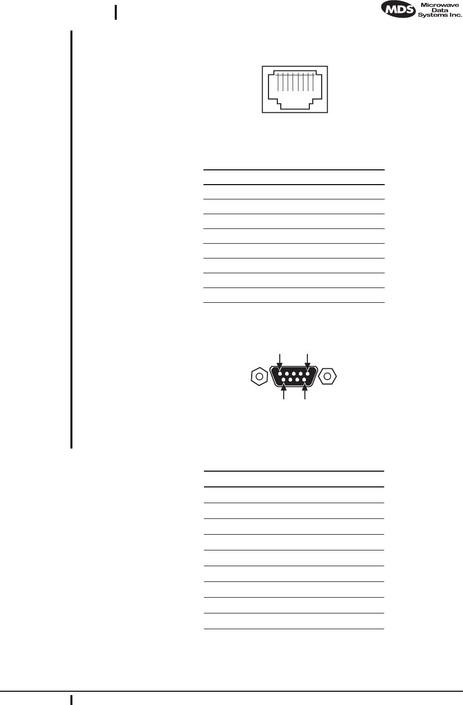
LAN (Local Area Network) Port—RJ-45 Ethernet Interface
The LAN Port is used to connect the radio to an Ethernet network. The
iNet transceiver will provide a data link to an Internet Protocol-based
(IP) data network through the radio network’s Access Point station.
Each radio transceiver in the network must have a unique IP address for
the network to function properly. The LAN port only supports the
Internet Protocol (IP).
CAUTION
RADIO FREQUENCY
INTERFERENCE
POTENTIAL
MDS 05-2873A01, Rev. A MDS iNet 900 Installation and Operation Guide 33
DRAFT 6—8/29/01
The connector uses the standard Ethernet RJ-45 cables and wiring.
Figure 18. LAN Port (RJ-11) Pinout
(Viewed from the outside of the radio.)
COM1 Port
Figure 19. COM1 Port
(Viewed from the outside of the radio.
Table 9-7. LAN Port (IP/Ethernet)
Pin Functions Ref.
1 Transmit Data (TX) High
2 Transmit Data (TX) Low
3 Receive Data (RX) High
4 Unused
5 Unused
6 Receive Data (RX) Low
7 Unused
8 Unused
Table 8. COM1 Port Pinout
Pin Functions DCE
1 Unused
2 Receive Data (RXD) <—[ Out
3 Transmit Data (TXD) —>[ In
4 Unused
5 Signal Ground (GND)
6 Unused
7 Unused
8 Unused
9 Unused
1 2 3 4 5 6 7 8
1
5
96

34 MDS iNet 900 Installation Guide MDS 05-2873A01, Rev. A
DRAFT 6—8/29/01
COM2 Port
Figure 20. COM2 Port
Viewed from the outside of the radio
9.3 Table-Top Test Setup
It may be convenient to set up table-top network that can be used to
verify the basic operation of the MDS iNet 900 transceivers and give
you a chance to experiment with network designs, configurations or net-
work equipment in a convenient location. This test can be performed
with any number of MDS iNet 900 radios.
To simulate data traffic over the radio network, connect a PC or LAN to
the Ethernet port of each radio. One of the MDS iNet 900 transceivers
in this mini-network must be set to the Access Point Mode for proper
operation.
NOTE: It is very important to use a “Network Name” that is different
from ones currently in use in your area during the testing
period. This will eliminate unnecessary traffic on the existing
network while you become familiar with the MDS iNet 900
transceivers or evaluate variations of unit operating parame-
ters.
Use any convenient antenna that can be connected to the transceiver’s
TNC connector. You may purchase a flexible one-quarter wavelength
antennas from Microwave Data Systems. (P/N xx-xxxxAxx)
5
1
69
Table 9. COM2 Port (DTE/DCE1)
(DB-9/RS-232 Interface, Output: Out ]–>, Input: In [<– )
Pin Functions DTE
1 Data Carrier Detect (DCD) In ]<—
2 Receive Data (RXD) In ]<—
3 Transmit Data (TXD) Out ]—>
4 Data Terminal Ready (DTR) Out ]—>
5 Signal Ground (GND)
6 Data Set Ready (DSR) In ]<—
7 Request-to-Send (RTS) Out ]—>
8 Clear-to-Send (CTS) In ]<—
9Unused
1. Default = DTE; User configurable to DCE

MDS 05-2873A01, Rev. A MDS iNet 900 Installation and Operation Guide 35
DRAFT 6—8/29/01
9.4 Using a Personal Computer to Configure the
iNet Radio
Any personal computer with either a serial port and terminal emulator
program if an Ethernet port can be used to access the iNet’s test and con-
figuration tool set. Once connected, the user will be provided with
on-line user instructions for each resource.
Connecting a PC to iNet’s LAN (Ethernet) Port
To connect a PC to the radio’s LAN port, an RJ-45 to RJ-45 cross-over
cable (MDS P/N 05-______A___) is required. If desired, this cable may
be purchased from a computer retail store or mail-order company.
Connecting a PC to iNet’s COM1 Port
To connect a PC to the radio’s COM1 port use a DB-9M to DB-9F
cross-over cable (MDS P/N 05-______A___). This cable may also be
purchased from a computer retail store or mail-order company.

36 MDS iNet 900 Installation Guide MDS 05-2873A01, Rev. A
DRAFT 6—8/29/01
10.0 GLOSSARY OF TERMS
If you are new to spread spectrum radio, some of the terms used in this
guide may be unfamiliar. The following glossary explains many of these
terms and will prove helpful in understanding the operation of the trans-
ceiver.
Antenna System Gain—A figure, normally expressed in dB, repre-
senting the power increase resulting from the use of a gain-type antenna.
System losses (from the feedline and coaxial connectors, for example)
are subtracted from this figure to calculate the total antenna system gain.
Bit—The smallest unit of digital data, often represented by a one or a
zero. Eight bits (plus start, stop, and parity bits) usually comprise a byte.
Bits-per-second—See BPS.
BPS—Bits-per-second. A measure of the information transfer rate of
digital data across a communication channel.
Byte—A string of digital data usually made up of eight data bits and
start, stop and parity bits.
Decibel (dB)—A measure of the ratio between two signal levels. Fre-
quently used to express the gain (or loss) of a system.
Data Circuit-terminating Equipment—See DCE.
Data Communications Equipment—See DCE.
Data Terminal Equipment—See DTE.
dBi—Decibels referenced to an “ideal” isotropic radiator in free space.
Frequently used to express antenna gain.
dBm—Decibels referenced to one milliwatt. An absolute unit used to
measure signal power, as in transmitter power output, or received signal
strength.
DCE—Data Circuit-terminating Equipment (or Data Communications
Equipment). In data communications terminology, this is the “modem”
side of a computer-to-modem connection.
DTE—Data Terminal Equipment. A device that provides data in the
form of digital signals at its output. Connects to the DCE device.
Equalization—The process of reducing the effects of amplitude, fre-
quency or phase distortion with compensating networks.

MDS 05-2873A01, Rev. A MDS iNet 900 Installation and Operation Guide 37
DRAFT 6—8/29/01
Fade Margin—The greatest tolerable reduction in average received
signal strength that will be anticipated under most conditions. Provides
an allowance for reduced signal strength due to multipath, slight antenna
movement or changing atmospheric losses. A fade margin of 20 to 30
dB is usually sufficient in most systems.
Frame—A segment of data that adheres to a specific data protocol and
contains definite start and end points. It provides a method of synchro-
nizing transmissions.
Frequency Hopping—The spread spectrum technique used by the
MDS iNet 900 transceivers, where two or more associated radios
change their operating frequencies several times per second using a set
pattern. Since the pattern appears to jump around, it is said to “hop”
from one frequency to another.
Frequency Zone—The transceivers use up to 1,019 discrete channels
in the 902 to 928 MHz spectrum. A group of 128 channels is referred to
as a zone. The transceivers use eight frequency zones. (Five channels are
reserved for network control purposes.)
Hardware Flow Control—A transceiver feature used to prevent data
buffer overruns when handling high-speed data from the RTU or PLC.
When the buffer approaches overflow, the radio drops the clear-to-send
(CTS) line, which instructs the RTU or PLC to delay further transmis-
sion until CTS again returns to the high state.
Host Computer—The computer installed at the Access Point station
site, which controls the collection of data from one or more remote sites.
Latency—The delay (usually expressed in milliseconds) between when
data is applied to TXD (Pin 2) at one radio, until it appears at RXD
(Pin 3) at the other radio.
MAS—Multiple Address System. A radio system where a central
Access Point station communicates with several Station Adaptors for
the purpose of gathering telemetry data.
Access Point (Station)—The one radio transceiver in a spread spectrum
network that automatically provides synchronization information to one
or more associated remote transceivers. A radio may be programmed for
either Access Point or remote mode using software commands. See Sec-
tion 6.0, PROGRAMMING (beginning on page 21).
MCU—Microcontroller Unit. This is the processor responsible for con-
trolling system start-up, synthesizer loading, hop timing, and key-up
control.
Microcontroller Unit—See MCU.

38 MDS iNet 900 Installation Guide MDS 05-2873A01, Rev. A
DRAFT 6—8/29/01
Mode—This refers to the programmed function of an MDS spread spec-
trum radio—Access Point or remote. (See also Station Adaptor and
Access Point Station.)
Multiple Address System (MAS)—See Point-Multipoint System.
Network Address—User-selectable number between 1 and 65000 that
is used to identify a group of transceivers that form a communications
network. The Access Point and all remotes within a given system must
have the same network address.1Z?
Network-Wide Diagnostics—An advanced method of controlling and
interrogating MDS radios in a radio network.
Point-Multipoint System—A radio communications network or
system designed with a central control station that exchanges data with
a number of remote locations equipped with terminal equipment.
Poll—A request for data issued from the host computer (or master PLC)
to a remote radio.
PLC—Programmable Logic Controller. A dedicated microprocessor
configured for a specific application with discrete inputs and outputs. It
can serve as a host or as an RTU.
Remote Radio—A radio in a spread spectrum network that communi-
cates with an associated Access Point station. A radio may be pro-
grammed for either Access Point or remote mode using software
commands. See Section 6.0, PROGRAMMING (beginning on page 21).
Remote Terminal Unit—See RTU.
RTU—Remote Terminal Unit. A data collection device installed at a
remote radio site.
SCADA—Supervisory Control And Data Acquisition. An overall term
for the functions commonly provided through an MAS radio system.
Standing Wave Ratio—See SWR.
SWR—Standing Wave Ratio. A parameter related to the ratio between
forward transmitter power and the reflected power from the antenna
system. As a general guideline, reflected power should not exceed 10%
of the forward power (≈ 2:1 SWR).
Zone—See Frequency Zone.
1. Is this relevant to this product?

MDS 05-2873A01, Rev. A MDS iNet 900 Installation and Operation Guide 39
DRAFT 6—8/29/01
10.1 dBm-Watts-Volts Conversion Chart
Table 10 is provided as a convenience for determining the equivalent
voltage or wattage of an RF power expressed in dBm.
Table 10. dBm-Watts-Volts conversion—for 50 ohm systems
dBm V Po
+53 100.0 200W
+50 70.7 100W
+49 64.0 80W
+48 58.0 64W
+47 50.0 50W
+46 44.5 40W
+45 40.0 32W
+44 32.5 25W
+43 32.0 20W
+42 28.0 16W
+41 26.2 12.5W
+40 22.5 10W
+39 20.0 8W
+38 18.0 6.4W
+37 16.0 5W
+36 14.1 4W
+35 12.5 3.2W
+34 11.5 2.5W
+33 10.0 2W
+32 9.0 1.6W
+31 8.0 1.25W
+30 7.10 1.0W
+29 6.40 800mW
+28 5.80 640mW
+27 5.00 500mW
+26 4.45 400mW
+25 4.00 320mW
+24 3.55 250mW
+23 3.20 200mW
+22 2.80 160mW
+21 2.52 125mW
+20 2.25 100mW
+19 2.00 80mW
+18 1.80 64mW
+17 1.60 50mW
+16 1.41 40mW
+15 1.25 32mW
+14 1.15 25mW
+13 1.00 20mW
+12 .90 16mW
+11 .80 12.5mW
+10 .71 10mW
+9 .64 8mW
+8 .58 6.4mW
+7 .500 5mW
+6 .445 4mW
+5 .400 3.2mW
+4 .355 2.5mW
+3 .320 2.0mW
+2 .280 1.6mW
+1 .252 1.25mW
dBm V Po
0 .225 1.0mW
-1 .200 .80mW
-2 .180 .64mW
-3 .160 .50mW
-4 .141 .40mW
-5 .125 .32mW
-6 .115 .25mW
-7 .100 .20mW
-8 .090 .16mW
-9 .080 .125mW
-10 .071 .10mW
-11 .064
-12 .058
-13 .050
-14 .045
-15 .040
-16 .0355
dBm mV Po
-17 31.5
-18 28.5
-19 25.1
-20 22.5 .01mW
-21 20.0
-22 17.9
-23 15.9
-24 14.1
-25 12.8
-26 11.5
-27 10.0
-28 8.9
-29 8.0
-30 7.1 .001mW
-31 6.25
-32 5.8
-33 5.0
-34 4.5
-35 4.0
-36 3.5
-37 3.2
-38 2.85
-39 2.5
-40 2.25 .1µW
-41 2.0
-42 1.8
-43 1.6
-44 1.4
-45 1.25
-46 1.18
-47 1.00
-48 0.90
dBm mV Po
-49 0.80
-50 0.71 .01µW
-51 0.64
-52 0.57
-53 0.50
-54 0.45
-55 0.40
-56 0.351
-57 0.32
-58 0.286
-59 0.251
-60 0.225 .001µW
-61 0.200
-62 0.180
-63 0.160
-64 0.141
dBm µV Po
-65 128
-66 115
-67 100
-68 90
-69 80
-70 71 .1nW
-71 65
-72 58
-73 50
-74 45
-75 40
-76 35
-77 32
-78 29
-79 25
-80 22.5 .01nW
-81 20.0
-82 18.0
-83 16.0
-84 11.1
-85 12.9
-86 11.5
-87 10.0
-88 9.0
-89 8.0
-90 7.1 .001nW
-91 6.1
-92 5.75
-93 5.0
-94 4.5
-95 4.0
-96 3.51
-97 3.2
dBm µV Po
-98 2.9
-99 2.51
-100 2.25 .1pW
-101 2.0
-102 1.8
-103 1.6
-104 1.41
-105 1.27
-106 1.18
dBm nV Po
-107 1000
-108 900
-109 800
-110 710 .01pW
-111 640
-112 580
-113 500
-114 450
-115 400
-116 355
-117 325
-118 285
-119 251
-120 225 .001pW
-121 200
-122 180
-123 160
-124 141
-125 128
-126 117
-127 100
-128 90
-129 80 .1ƒW
-130 71
-131 61
-132 58
-133 50
-134 45
-135 40
-136 35
-137 33
-138 29
-139 25
-140 23 .01ƒW

40 MDS iNet 900 Installation Guide MDS 05-2873A01, Rev. A
DRAFT 6—8/29/01
NOTES

IN CASE OF DIFFICULTY...
MDS products are designed for long life and trouble-free operation. However, this equipment, as
with all electronic equipment may have an occasional component failure. The following informa-
tion will assist you in the event that servicing becomes necessary.
FACTORY TECHNICAL ASSISTANCE
Technical assistance for MDS products is available from our Customer Support Team during busi-
ness hours (8:00 A.M.–5:30 P.M. Eastern Time). When calling, please give the complete model
number of the radio, along with a description of the trouble symptom(s) that you are experiencing.
In many cases, problems can be resolved over the telephone, without the need for returning the unit
to the factory.
Please use the following telephone numbers for product assistance:
716-241-5510 (Phone)
716-242-8369 (FAX)
FACTORY REPAIRS
Component-level repair of radio equipment is not recommended in the field. Many components are
installed using surface mount technology, which requires specialized training and equipment for
proper servicing. For this reason, the equipment should be returned to the factory for any PC board
repairs. The factory is best equipped to diagnose, repair and align your radio to its proper operating
specifications.
If return of the equipment is necessary, you will be issued a Returned Material Authorization
(RMA) number. The RMA number will help expedite the repair so that the equipment can be
repaired and returned to you as quickly as possible. Please be sure to include the RMA number on
the outside of the shipping box, and on any correspondence relating to the repair. No equipment
will be accepted for repair without an RMA number.
A statement should accompany the radio describing, in detail, the trouble symptom(s), and a
description of any associated equipment normally connected to the radio. It is also important to
include the name and telephone number of a person in your organization who can be contacted if
additional information is required.
The radio must be properly packed for return to the factory. The original shipping container and
packaging materials should be used whenever possible. All factory returns should be addressed to:
When repairs have been completed, the equipment will be returned to you by the same shipping
method used to send it to the factory. Please specify if you wish to make different shipping arrange-
ments.
Microwave Data Systems Inc.
Customer Service Department
(RMA No. XXXX)
175 Science Parkway
Rochester, NY 14620 USA

175 Science Parkway, Rochester, New York 14620
General Business: +1 (716) 242-9600
FAX: +1 (716) 242-9620
Web: www.microwavedata.com