GE MDS LEDR400S-74 LEDR 400S Microwave Radio User Manual 3627C LEDR Body
GE MDS LLC LEDR 400S Microwave Radio 3627C LEDR Body
GE MDS >
Contents
- 1. Operating Instructions Part 1 of 2
- 2. Operating Instructions Part 2 of 2
Operating Instructions Part 2 of 2
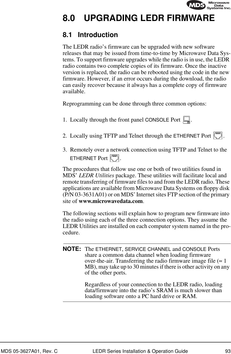
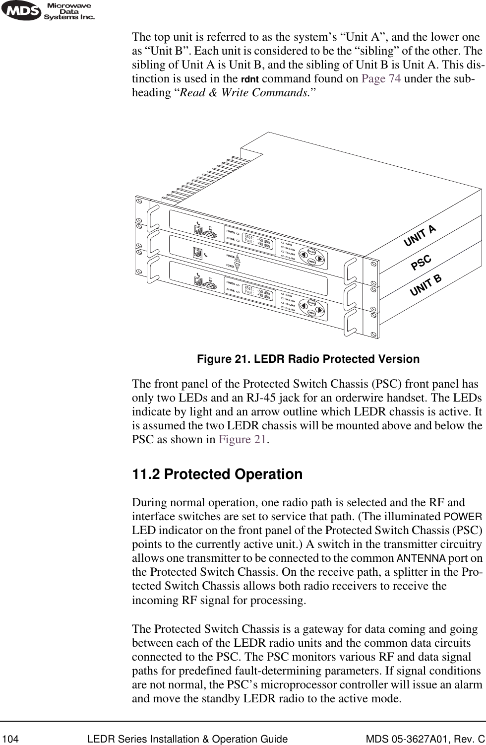
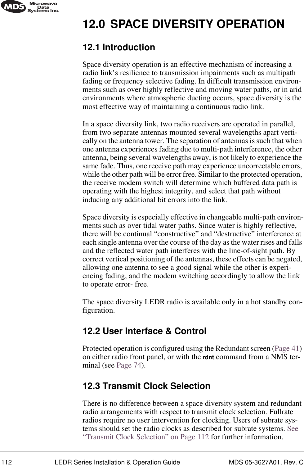
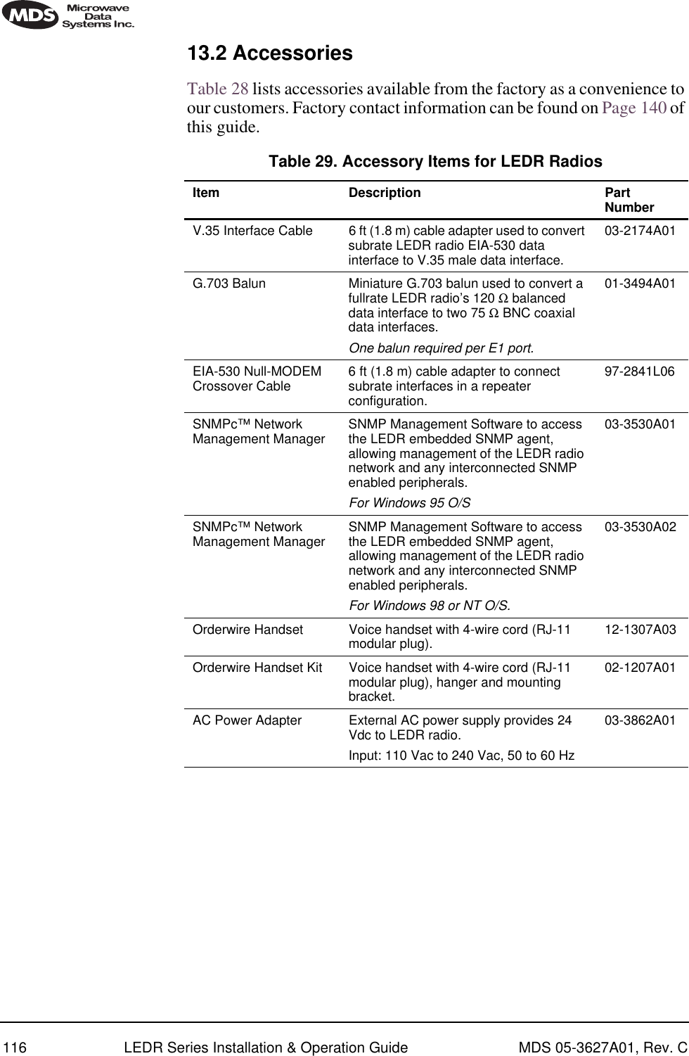
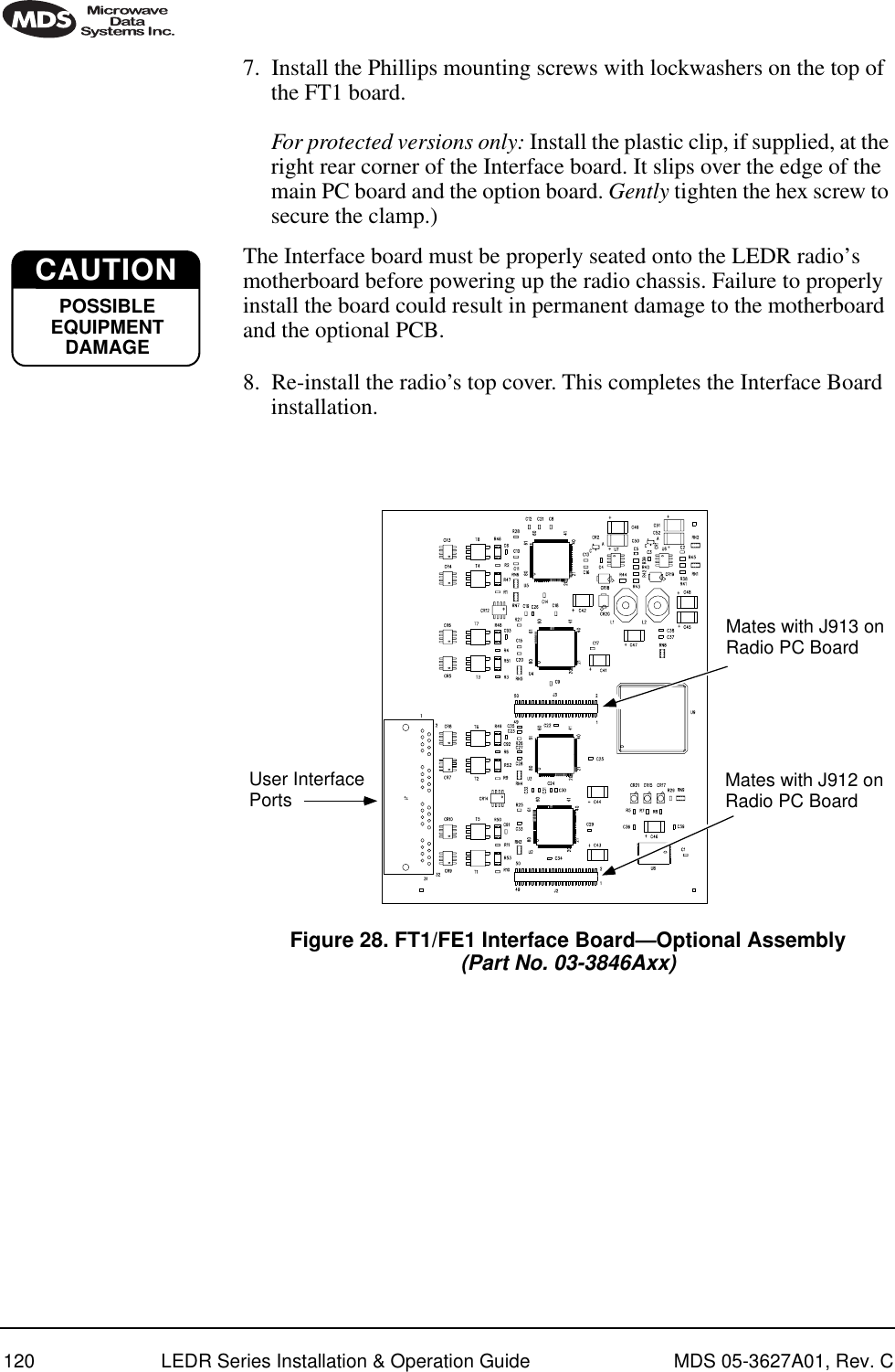
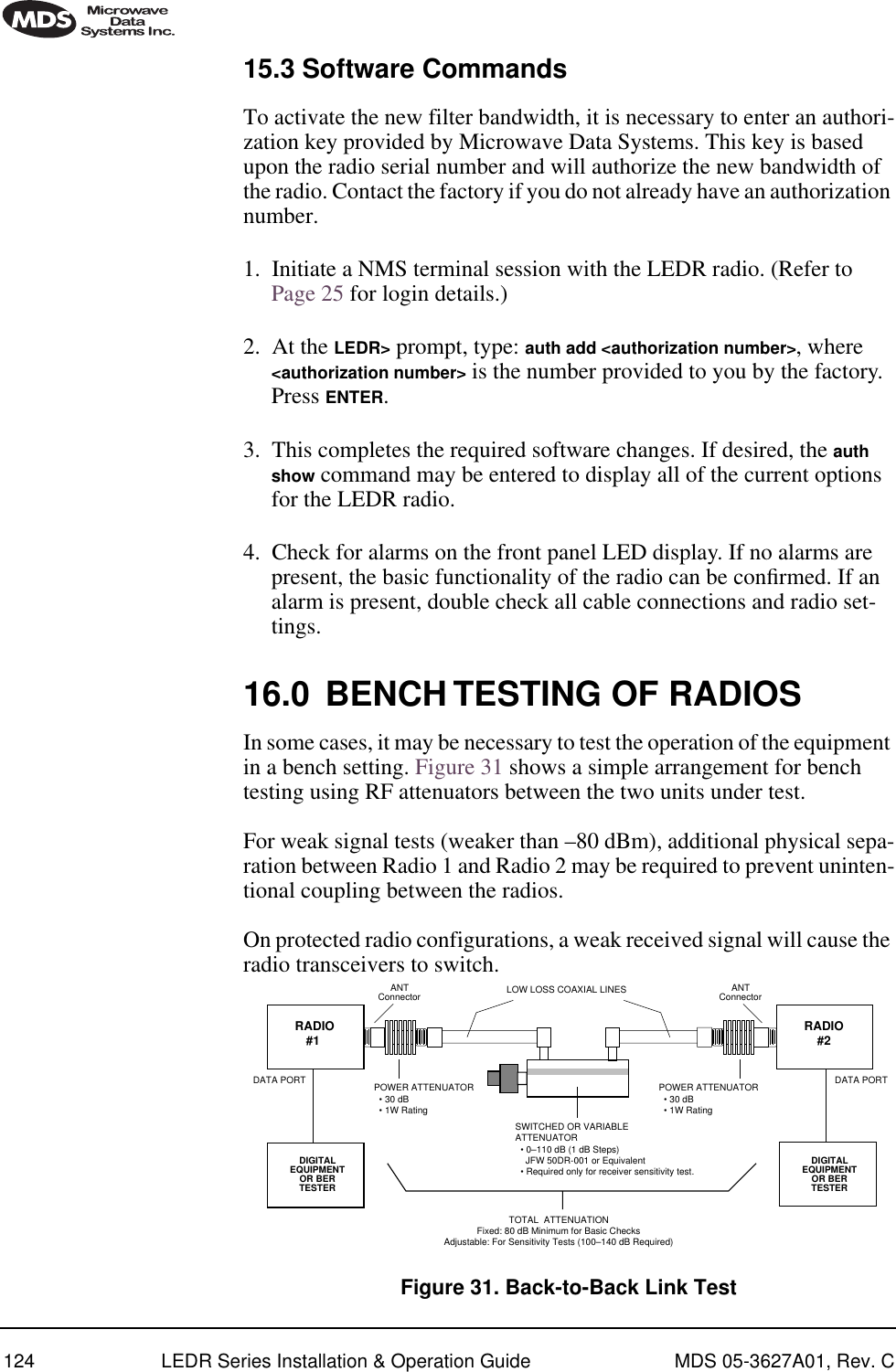
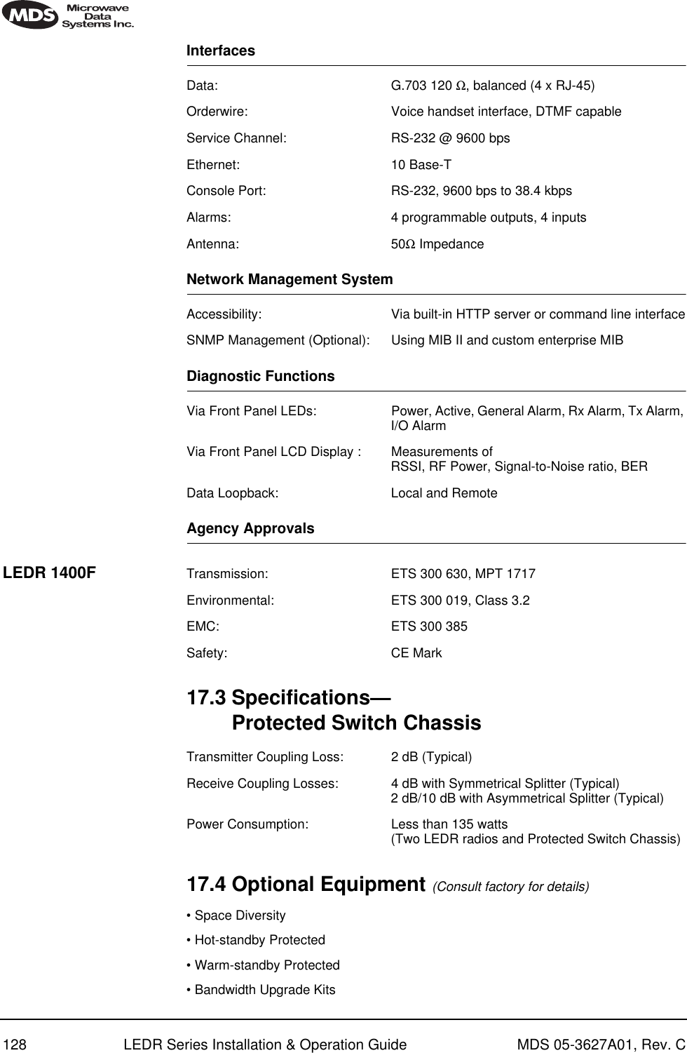
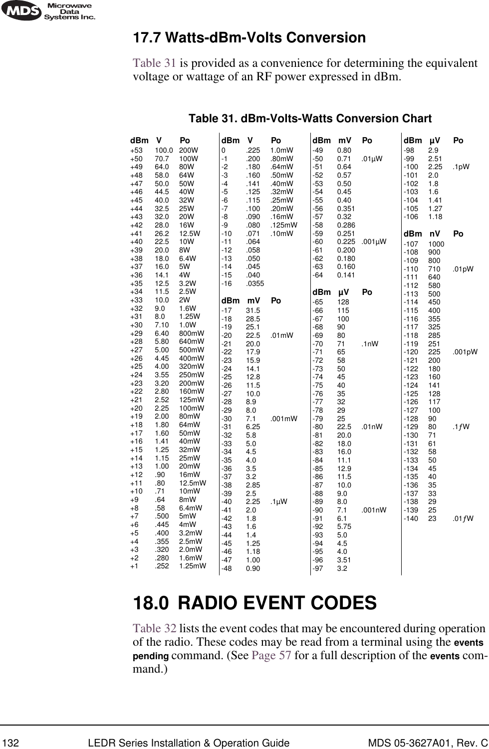
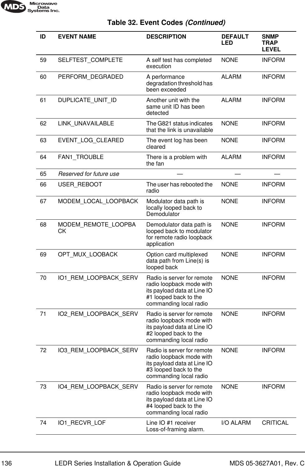
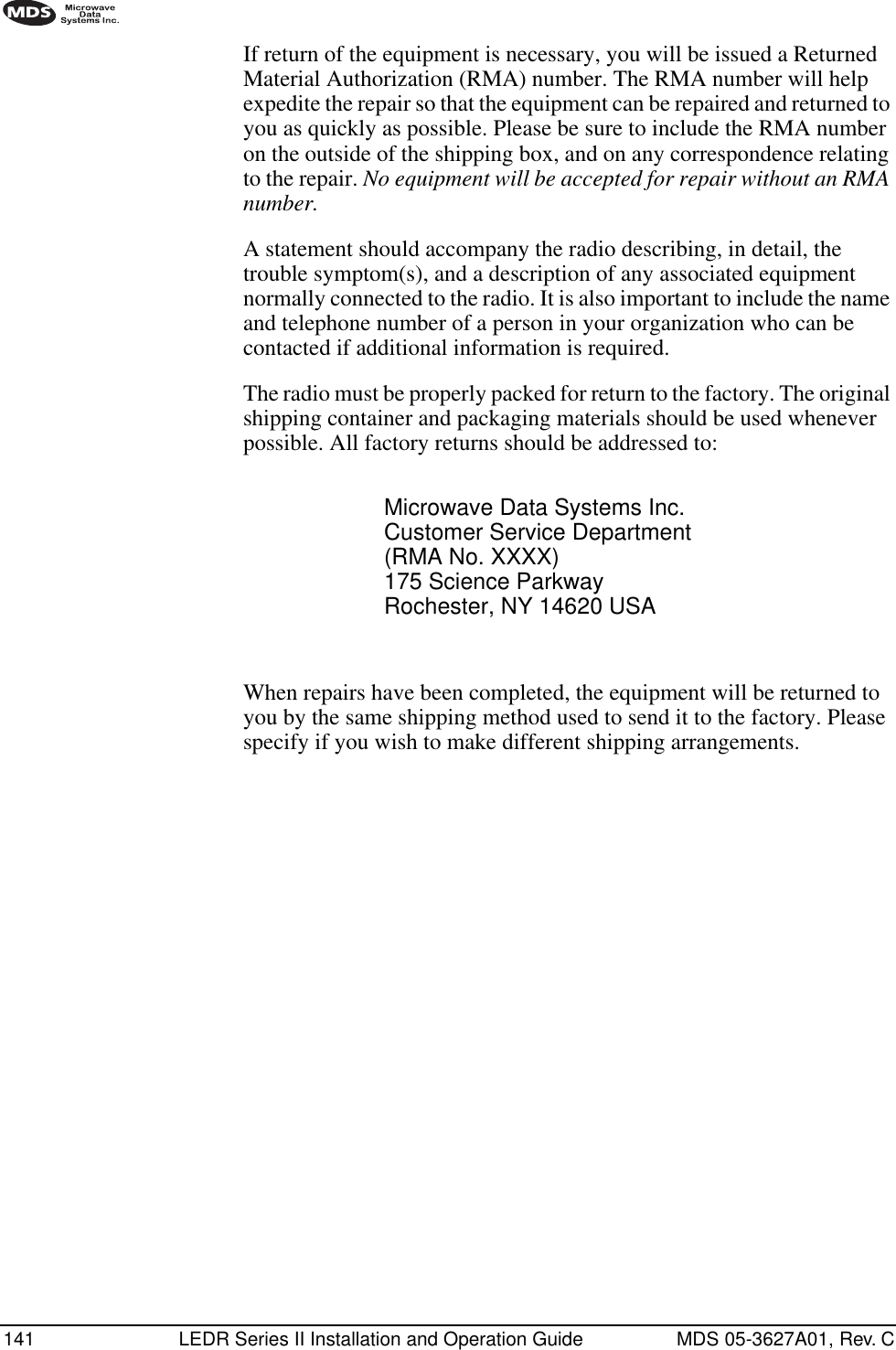
![96 LEDR Series Installation & Operation Guide MDS 05-3627A01, Rev. CInvisible place holderFigure 18. Direct connection through the LEDR ETHERNET PortSetup1. Connect the PC’s Ethernet interface to the radio’s ETHERNET Port using a Category 5 Ethernet cross-over cable.2. Copy the file LEDR firmware image file (ledr.mpk) into a known directory on your PC. For example, c:\windows\LEDR\Firmware V2.5\. This directory path will be used later by the TFTP server.Download Procedure1. Launch the MDS TFTP Server on a PC connected to the LEDR radio’s ETHERNET Port through a cross-connect cable.2. Point the TFTP server to the directory from which you desire to upload the new firmware. In the SNMP TFTP server, you should execute the set root command and point to the known directory where ledr.mpk has been copied.3. Launch your Telnet application and login to the radio which you desire to load (reprogram) the firmware image file.4. Determine the active (firmware) image from which you are currently executing by typing boot. The new firmware will downloaded into the inactive image. 5. Execute the command reprogram network ledr.mpk [IP address]. In the command, in place of [IP address], you should actually type the IP address of the TFTP server. For example, reprogram network ledr.mpk 192.168.1.2& TELNET ETHERNETPORTINITIATE UPLOADFROM HERELEDR RADIO UNITLOCAL WINDOWS PCW/FIRMWARE FILESETHERNETPORTLEDR> REPROGRAM NETWORK FILENAME.MPK 192.168.X.B(CHECK STATUS: LEDR> REPROGRAM STATUS)IP ADDRESS: 192.168.X.BCROSS-OVER CABLEIP ADDRESS: 192.168.X.WTFTPSERVER](https://usermanual.wiki/GE-MDS/LEDR400S-74.Operating-Instructions-Part-2-of-2/User-Guide-162758-Page-4.png)
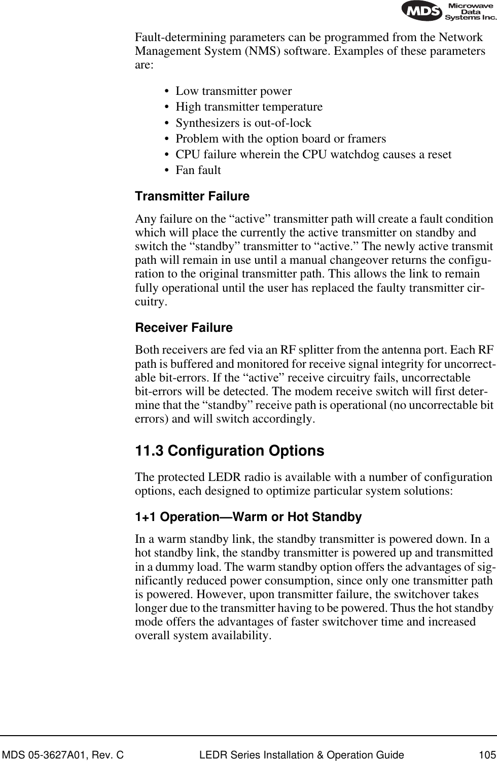
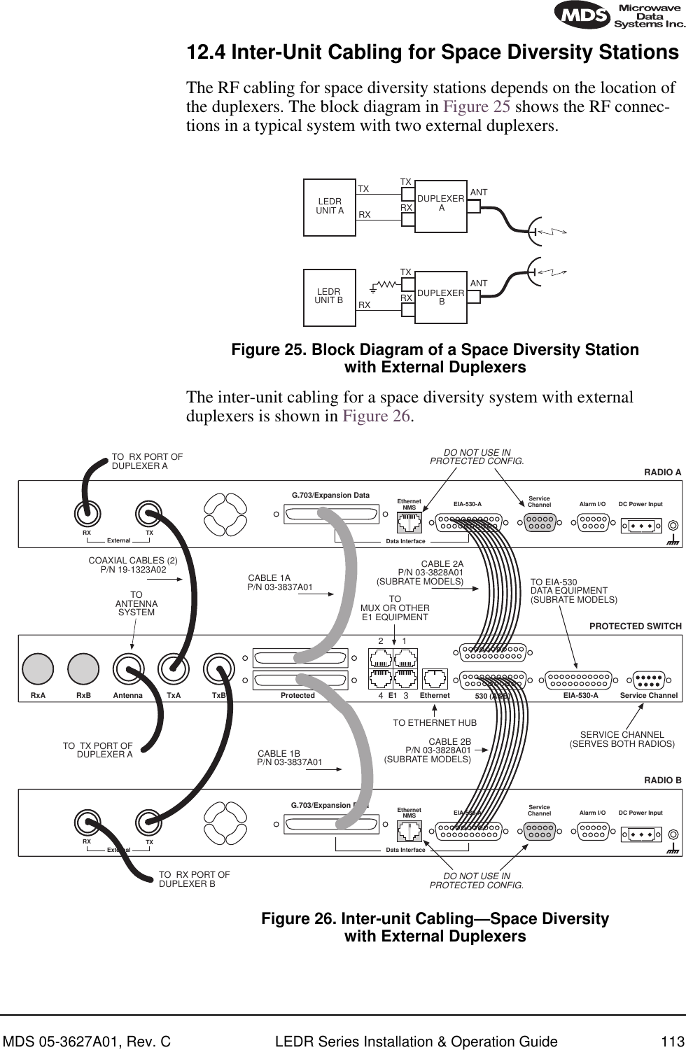
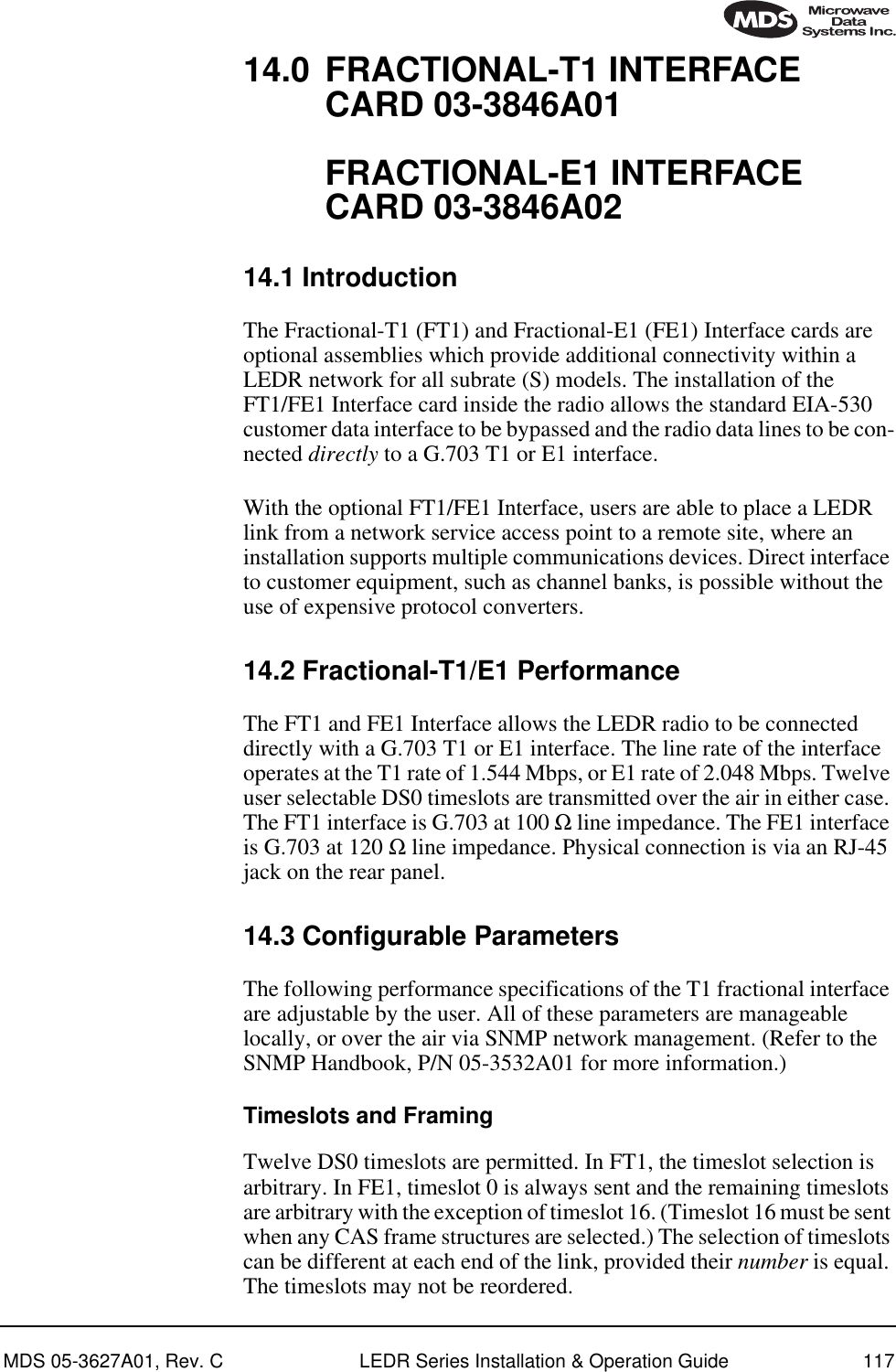
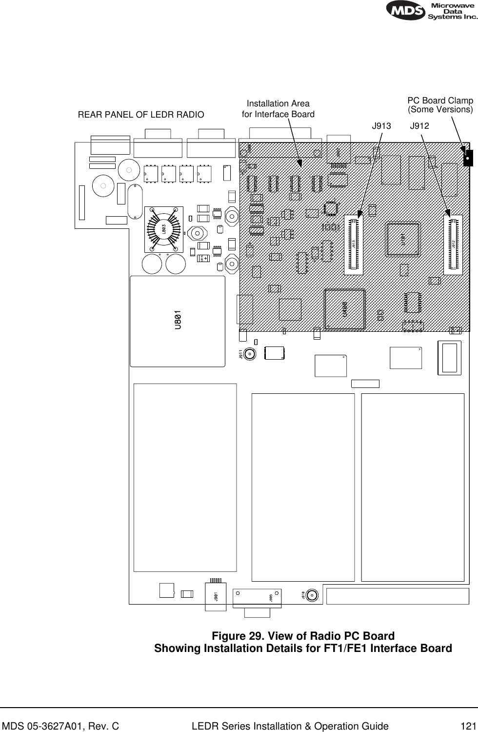
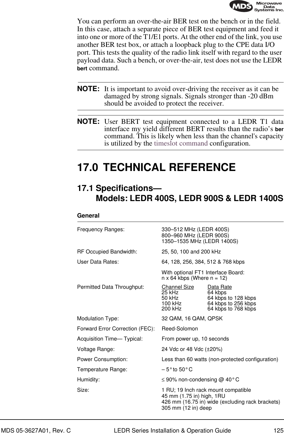
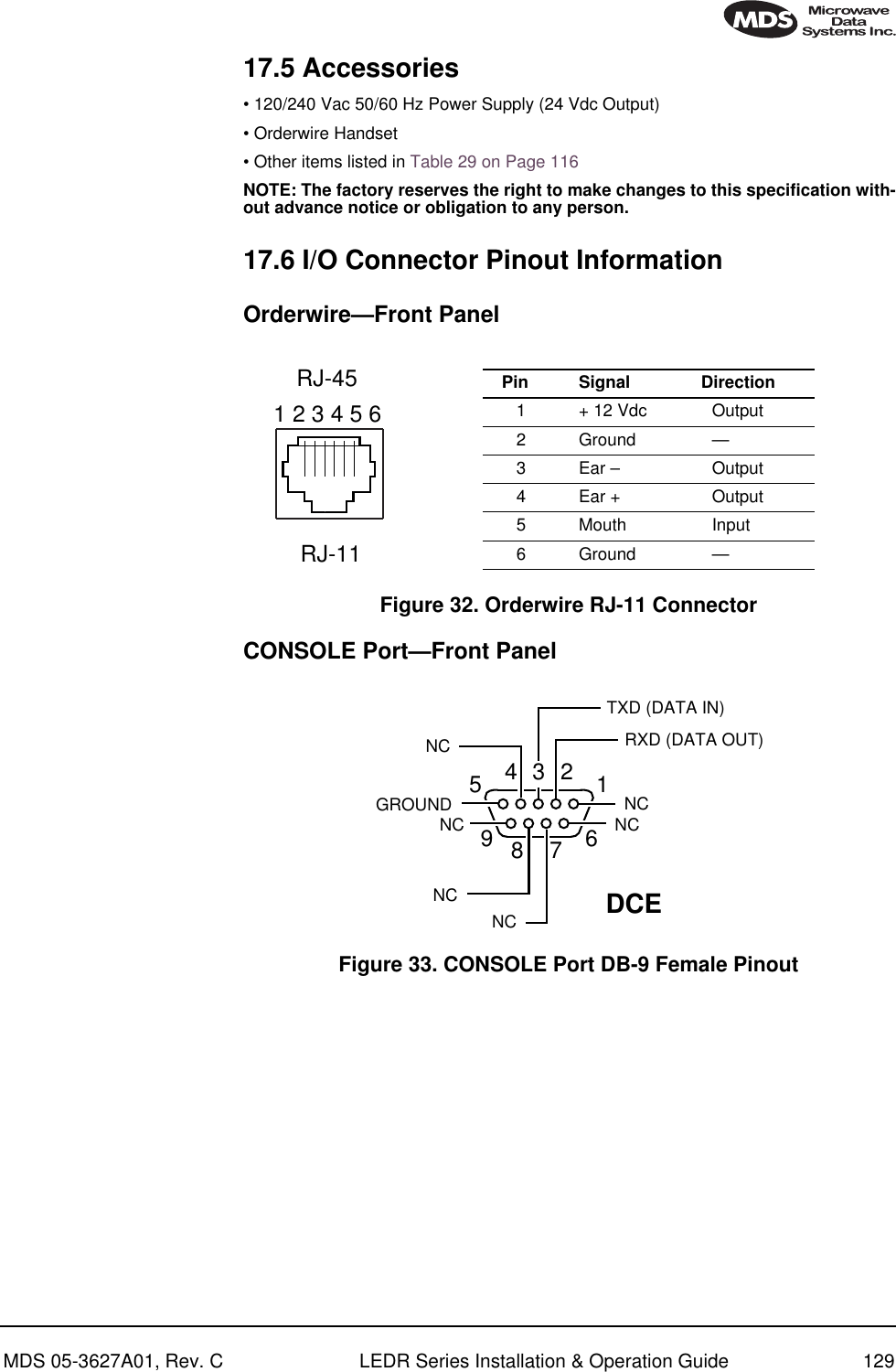
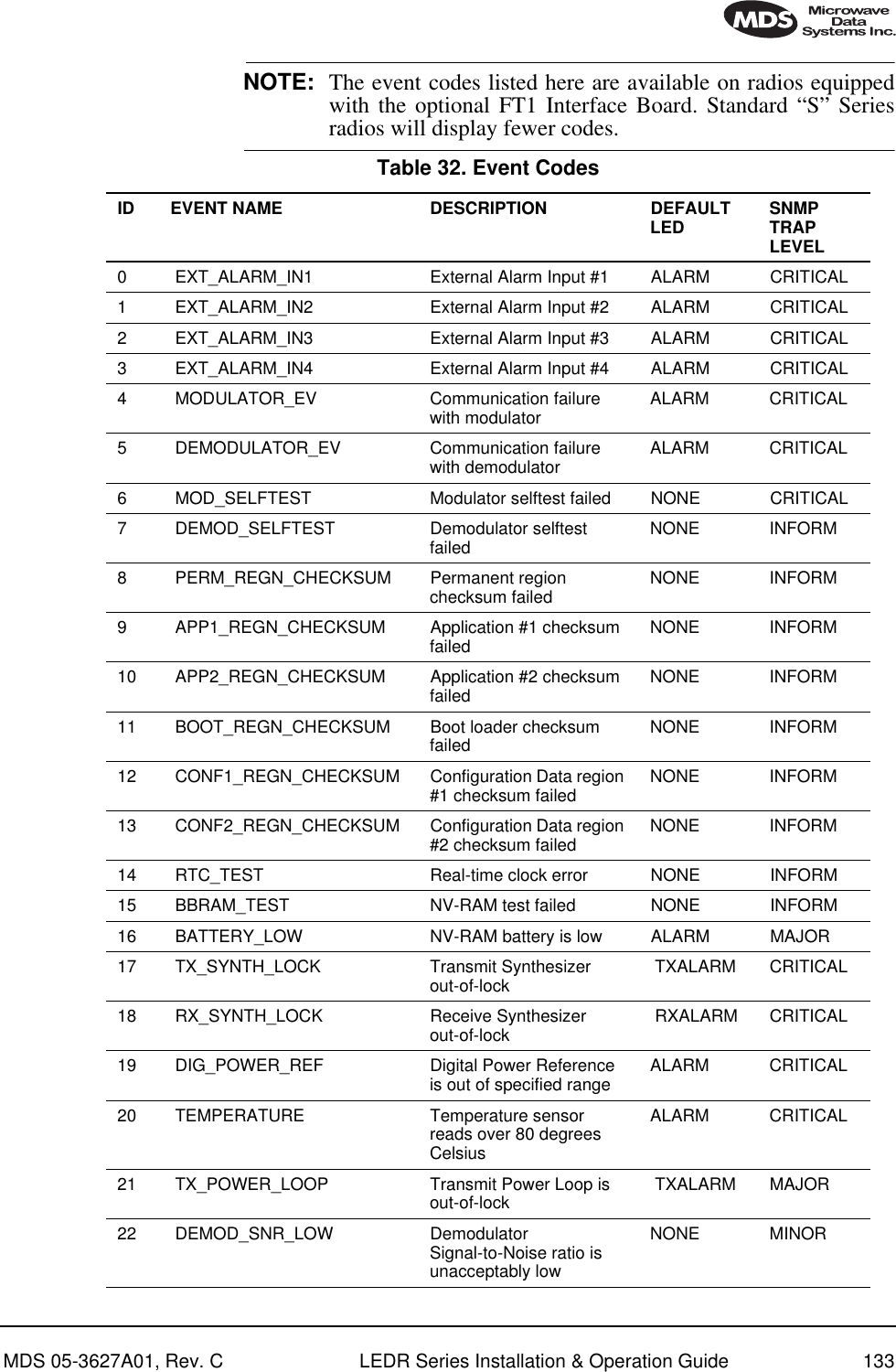
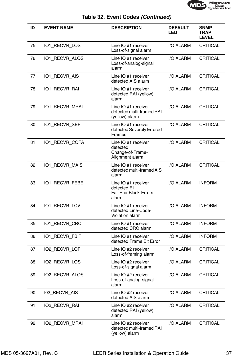
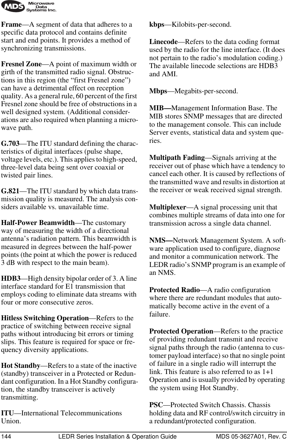
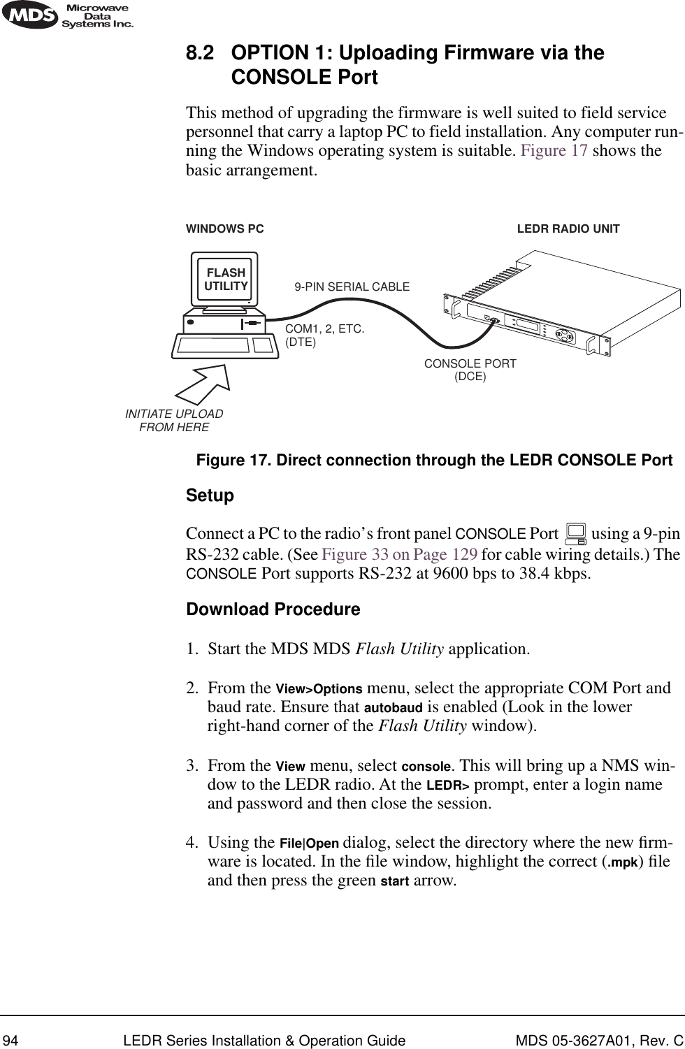
![98 LEDR Series Installation & Operation Guide MDS 05-3627A01, Rev. CThe computer hosting the firmware image, must be running a TFTP server software. If not, install, launch and configure the MDS TFTP Server software found on the LEDR Utilities disk. The setup configura-tion is shown in Figure 19.Invisible place holderFigure 19. Uploading firmware from a remote server via Ethernet Download Procedure1. Start a terminal program, such as HyperTerminal, on the local PC. 2. Log into the LEDR radio using the login command. 3. Use the ip command to ensure that the radio has a valid IP address. 4. Use the ping command from the local PC to ensure that the PC and the radio have valid routes to pass information between them.5. At the radio’s LEDR> prompt, start the download by entering repro-gram network [filename] [source PC’s IP Address]. The download can be monitored from the radio by entering reprogram status. When the download is complete the radio will sound two short beeps and the response from reprogram status will indicate that the download has finished.TFTPSERVER ETHERNETPORT9-PIN SERIALCABLECONSOLE PORT(DCE)INITIATE UPLOADFROM HERELEDR RADIO UNITREMOTE PCW/FIRMWARE FILES HUB/LAN/WAN/MANTCP/IPETHERNETPORTCOM1, 2, ETC.(DTE)TERMPROG.LEDR> REPROGRAM NETWORK FILENAME.MPK 192.168.X.B(CHECK STATUS: LEDR> REPROGRAM STATUS)IP ADDRESS: 192.168.X.BIP ADDRESS: 192.168.X.WLOCAL WINDOWS PC](https://usermanual.wiki/GE-MDS/LEDR400S-74.Operating-Instructions-Part-2-of-2/User-Guide-162758-Page-6.png)
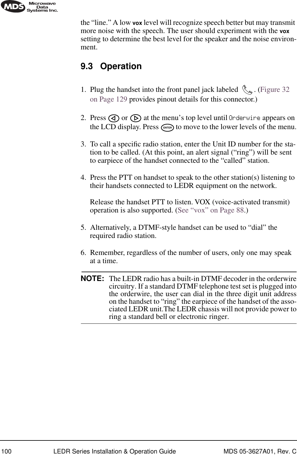
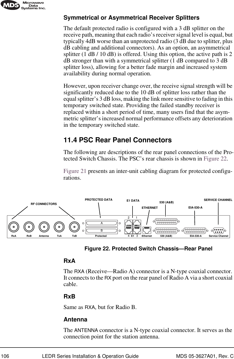
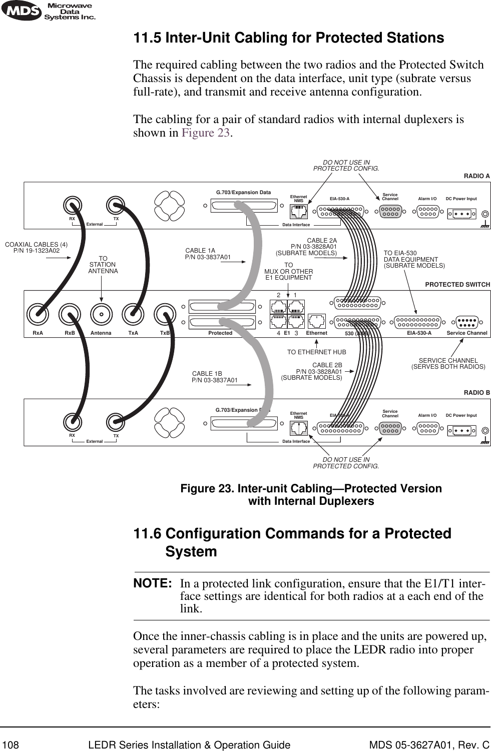
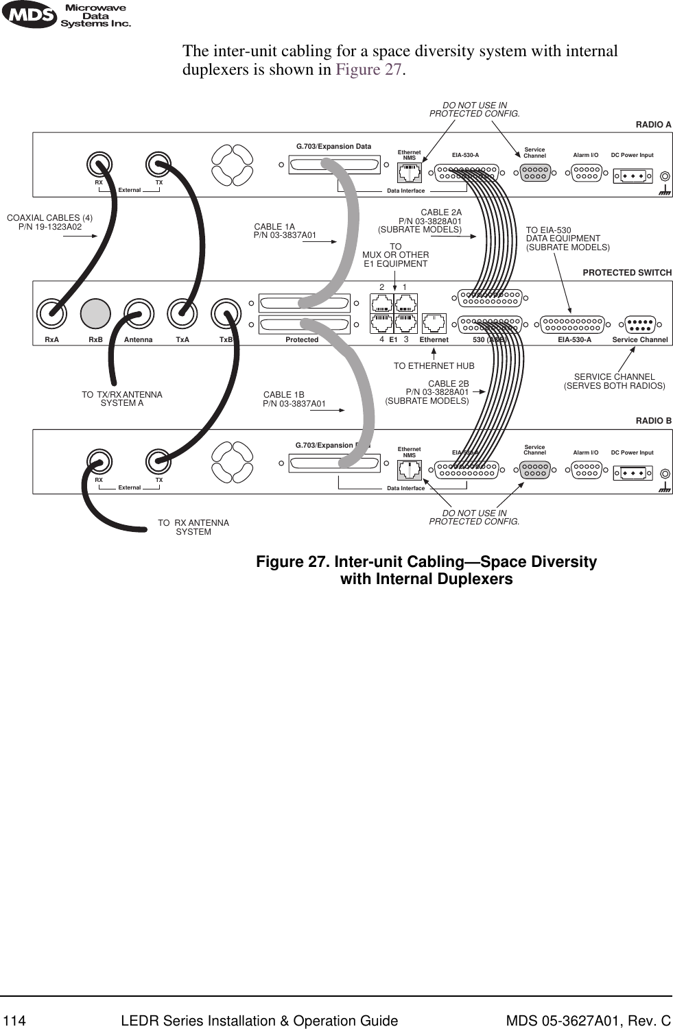
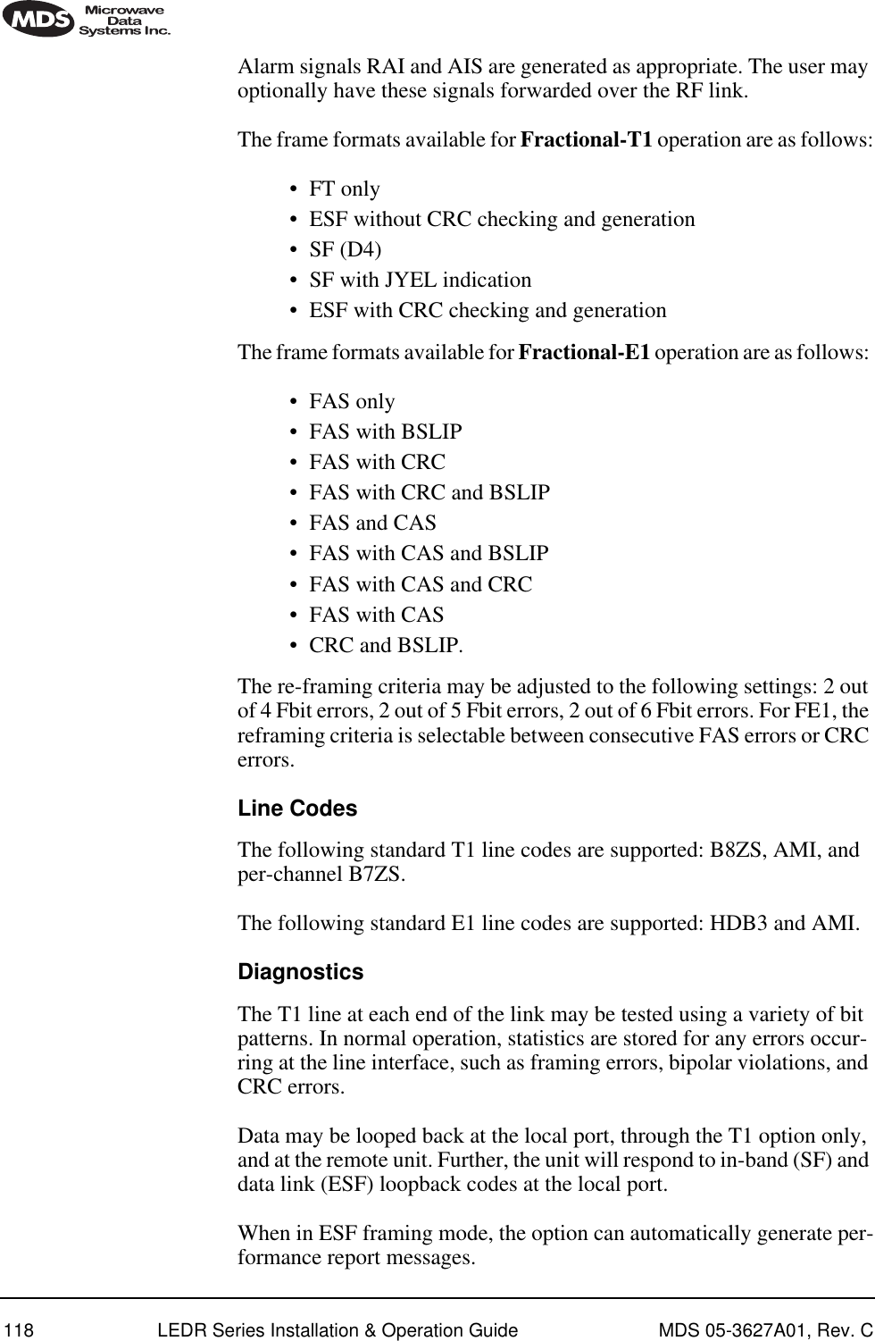
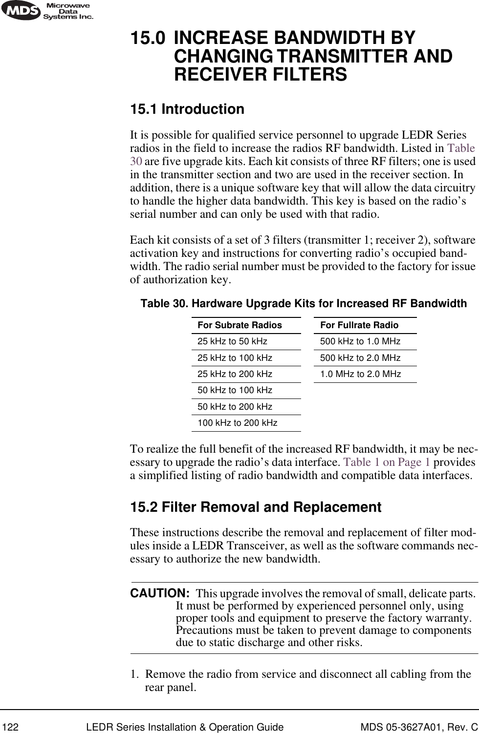
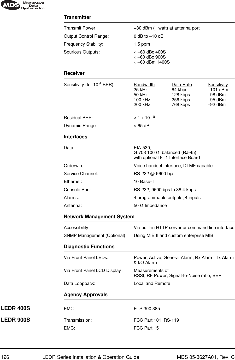
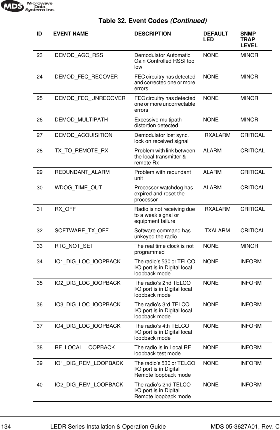
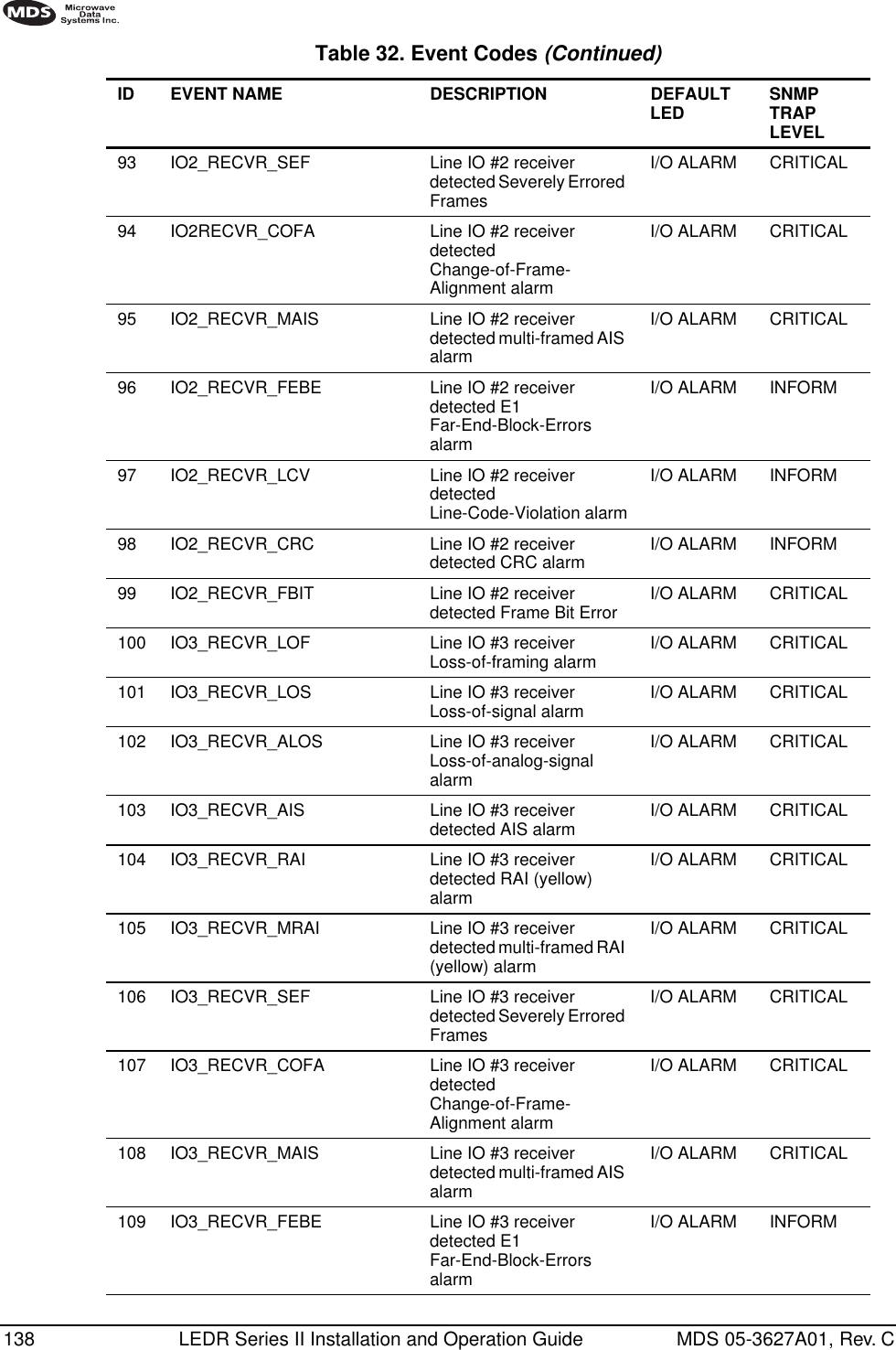
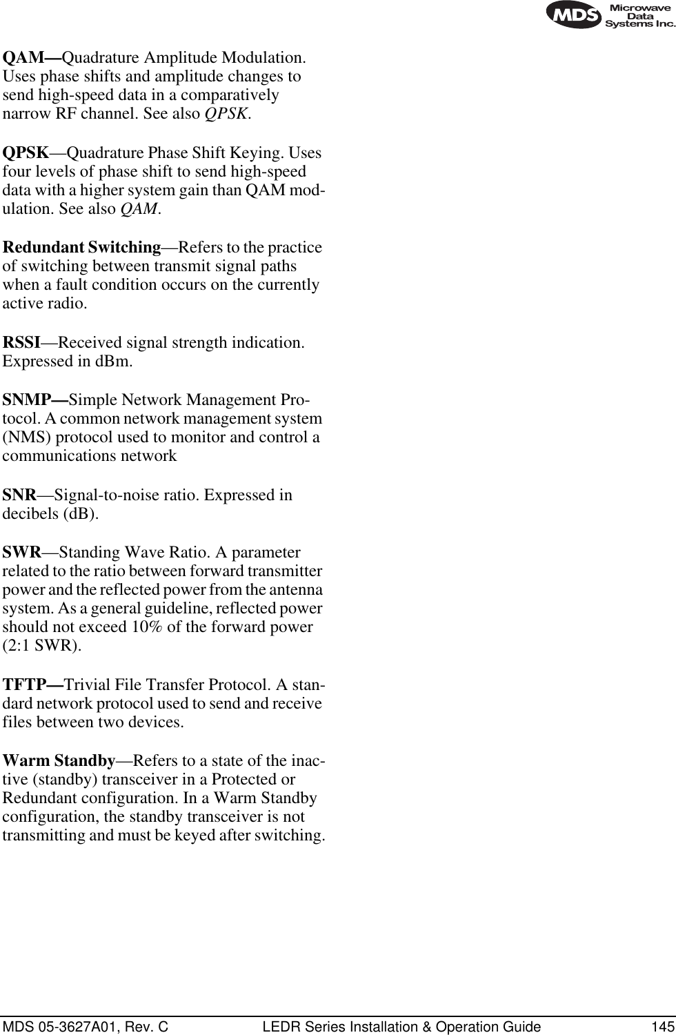
![MDS 05-3627A01, Rev. C LEDR Series Installation & Operation Guide 10310.4 NMS CommandsThis command is used to set/display Service Channel parameters.Usage: svch [subcommand] [<argument>] Subcommands: baudcharechooffoffonparityresetstopon—Enable the Service Channeloff—Disable the Service Channelreset—Re-initialize the Service Channelecho—on/offbaud—300, 600, 1200, 2400, 4800 and 9600char— 5, 6, 7, 8 (ASCII character length in bits)parity—none, even, oddstop—1, 2 (Stop bits)11.0 PROTECTED CONFIGURATION11.1 IntroductionThe LEDR radio can be supplied in a protected (also called redundant or “1+1”) configuration (Figure 21). The protected version is designed to perform automatic switchover to a second radio in the event of a failure in the primary unit.Protected operation is important for many mission-critical or revenue producing links. By configuring two identical LEDR radios in parallel and including a third switch box containing the RF switching circuits and the customer interfaces, it is possible to protect against failure in any of the LEDR radio sub-systems. Failures can be either malfunction or external environmental effects, such as multipath fading or nearby light-ning strikes.A Protected station consists of two standard LEDR Series radios and a Protected Switch Chassis (center unit in Figure 21). Ordinarily, the three chassis are mounted together in a “stacked” arrangement, one above the other, as shown in the figure.](https://usermanual.wiki/GE-MDS/LEDR400S-74.Operating-Instructions-Part-2-of-2/User-Guide-162758-Page-11.png)