GE MDS LEDR400S-74 LEDR 400S Microwave Radio User Manual 3627C LEDR Body
GE MDS LLC LEDR 400S Microwave Radio 3627C LEDR Body
GE MDS >
Contents
- 1. Operating Instructions Part 1 of 2
- 2. Operating Instructions Part 2 of 2
Operating Instructions Part 2 of 2

MDS 05-3627A01, Rev. C LEDR Series Installation & Operation Guide 93
8.0 UPGRADING LEDR FIRMWARE
8.1 Introduction
The LEDR radio’s firmware can be upgraded with new software
releases that may be issued from time-to-time by Microwave Data Sys-
tems. To support firmware upgrades while the radio is in use, the LEDR
radio contains two complete copies of its firmware. Once the inactive
version is replaced, the radio can be rebooted using the code in the new
firmware. However, if an error occurs during the download, the radio
can easily recover because it always has a complete copy of firmware
available.
Reprogramming can be done through three common options:
1. Locally through the front panel CONSOLE Port .
2. Locally using TFTP and Telnet through the ETHERNET Port .
3. Remotely over a network connection using TFTP and Telnet to the
ETHERNET Port .
The procedures that follow use one or both of two utilities found in
MDS’ LEDR Utilities package. These utilities will facilitate local and
remote transferring of firmware files to and from the LEDR radio. These
applications are available from Microwave Data Systems on floppy disk
(P/N 03-3631A01) or on MDS’ Internet sites FTP section of the primary
site of www.microwavedata.com.
The following sections will explain how to program new firmware into
the radio using each of the three connection options. They assume the
LEDR Utilities are installed on each computer system named in the pro-
cedure.
NOTE: The ETHERNET, SERVICE CHANNEL and CONSOLE Ports
share a common data channel when loading firmware
over-the-air. Transferring the radio firmware image file (≈ 1
MB), may take up to 30 minutes if there is other activity on any
of the other ports.
Regardless of your connection to the LEDR radio, loading
data/firmware into the radio’s SRAM is much slower than
loading software onto a PC hard drive or RAM.
94 LEDR Series Installation & Operation Guide MDS 05-3627A01, Rev. C
8.2 OPTION 1: Uploading Firmware via the
CONSOLE Port
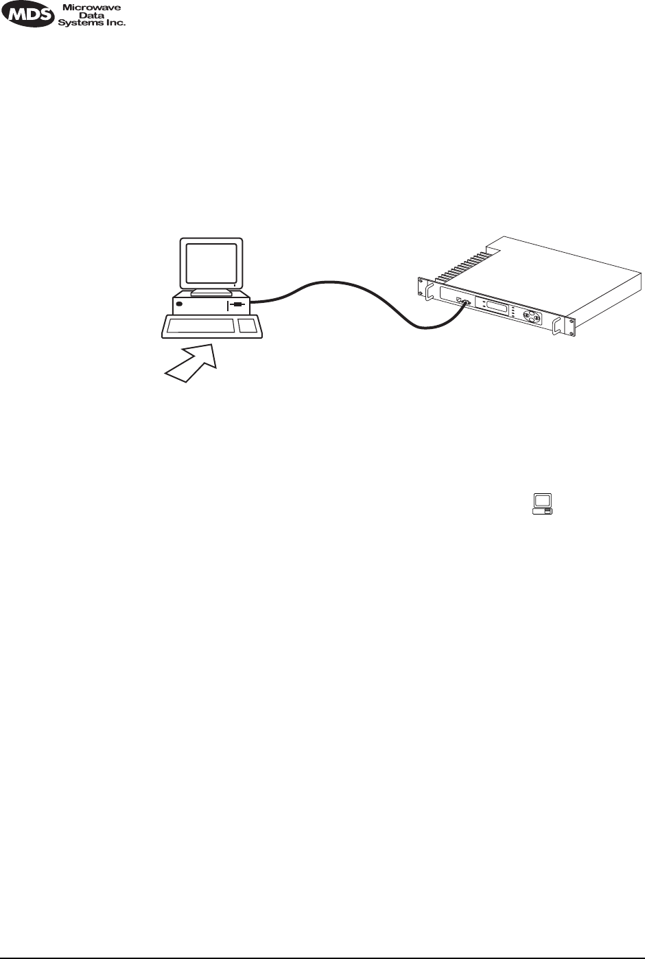
This method of upgrading the firmware is well suited to field service
personnel that carry a laptop PC to field installation. Any computer run-
ning the Windows operating system is suitable. Figure 17 shows the
basic arrangement.
Invisible place holder
Figure 17. Direct connection through the LEDR CONSOLE Port
Setup
Connect a PC to the radio’s front panel CONSOLE Port using a 9-pin
RS-232 cable. (See Figure 33 on Page 129 for cable wiring details.) The
CONSOLE Port supports RS-232 at 9600 bps to 38.4 kbps.
Download Procedure
1. Start the MDS MDS Flash Utility application.
2. From the View>Options menu, select the appropriate COM Port and
baud rate. Ensure that autobaud is enabled (Look in the lower
right-hand corner of the Flash Utility window).
3. From the View menu, select console. This will bring up a NMS win-
dow to the LEDR radio. At the LEDR> prompt, enter a login name
and password and then close the session.
4. Using the File|Open dialog, select the directory where the new firm-
ware is located. In the file window, highlight the correct (.mpk) file
and then press the green start arrow.
FLASH
UTILITY
COM1, 2, ETC.
(DTE)
9-PIN SERIAL CABLE
CONSOLE PORT
(DCE)
INITIATE UPLOAD
FROM HERE
LEDR RADIO UNITWINDOWS PC

MDS 05-3627A01, Rev. C LEDR Series Installation & Operation Guide 95
Verification and Reboot
1. To verify the correct operation of the new firmware, open the NMS
again by pressing Alt + L. Enter boot to determine which image is
currently active. This command will respond as follows:
boot: Image 1 is Active or, boot: Image 2 is Active
2. The new firmware is downloaded into the inactive image. Therefore,
if the radio responded Image 1 is Active, enter “image verify” com-
mand, iverify 2, otherwise, enter iverify 1. The radio will respond indi-
cating whether or not the image has been verified as being a valid
file, it will not determine if the contents are complementary to the
other firmware image. If the image does not verify, try downloading
the firmware again into the radio.
NOTE: The following paragraph describes rebooting the radio. This
action will disrupt the communications link.
3. Once the image has been verified, the radio must be rebooted using
the new firmware. This is done by entering the command boot 1 or
boot 2, where the 1 or 2 corresponds with the image number used
with the iverify command above.
4. Once the radio has rebooted and Flash Utility screen displays the
LEDR> prompt, the firmware can be downloaded or copied into the
other image. Often, copying the firmware from one image to the
other can be faster than performing a second download. To copy the
firmware over to the other image, simply enter icopy. The radio will
prompt you for confirmation (y/n) and then begin copying.
8.3 OPTION 2: Uploading Firmware Locally by
Telnet via Ethernet
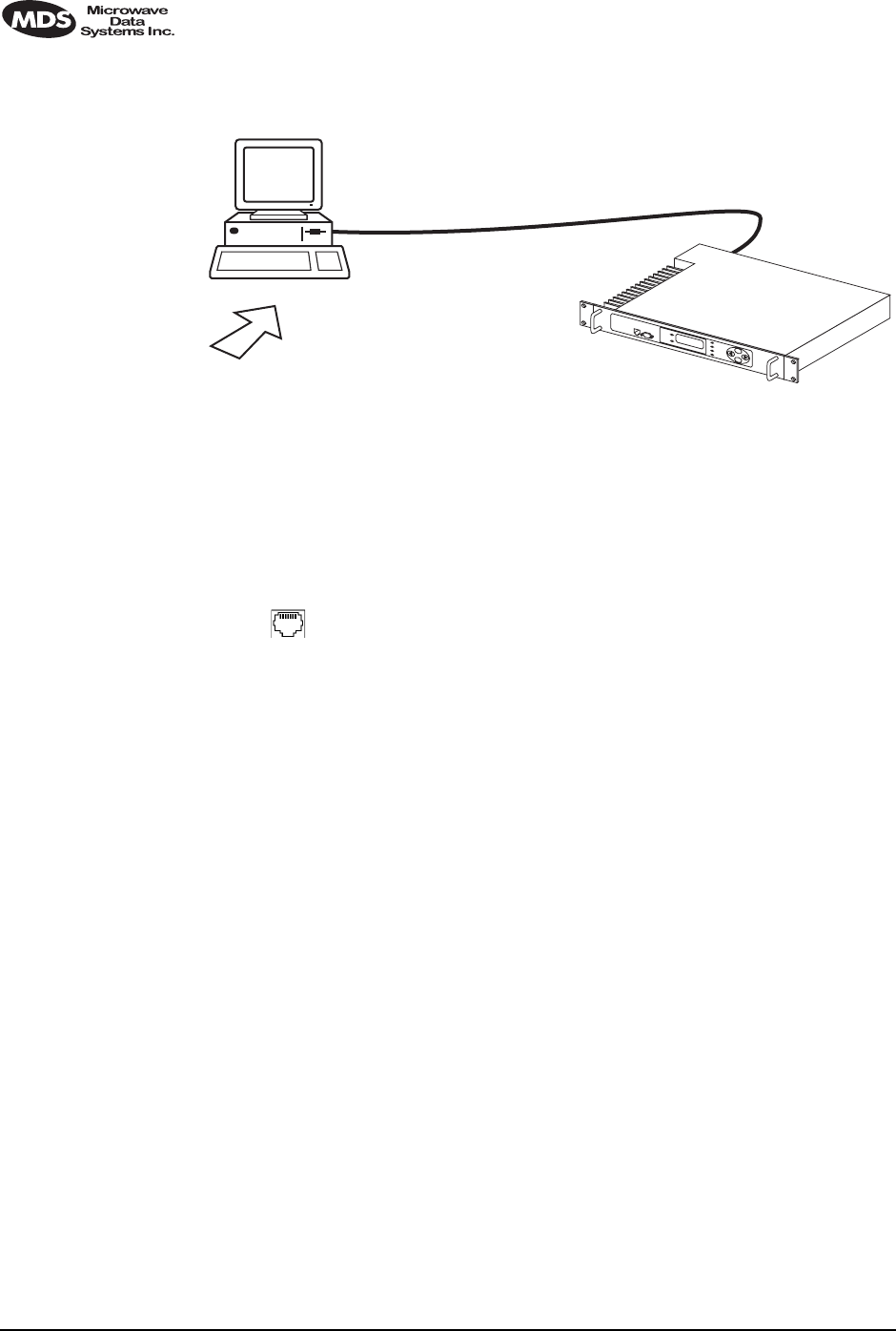
This method can be used in the field or in a workshop by using a Win-
dows computer equipped with an Ethernet interface. Figure 17 shows
the basic arrangement.
NOTE: You must know the IP address of the LEDR Radio and the PC
that you are going to connect together. (Both units must have
the same Subnet, Netmask and Gateway addresses, or at least
have routes to one another.) This is essential for a direct
Ethernet connection.
If you do not know your Windows computer’s IP address, you
can use the RUN function from the Start menu and enter winipcfg
to determine your local PC’s IP address. The IP address of the
radio can be found by the use of the radio’s ip command.
96 LEDR Series Installation & Operation Guide MDS 05-3627A01, Rev. C
Invisible place holder
Figure 18. Direct connection through the LEDR ETHERNET Port
Setup
1. Connect the PC’s Ethernet interface to the radio’s ETHERNET Port
using a Category 5 Ethernet cross-over cable.
2. Copy the file LEDR firmware image file (ledr.mpk) into a known
directory on your PC. For example, c:\windows\LEDR\Firmware V2.5\.
This directory path will be used later by the TFTP server.
Download Procedure
1. Launch the MDS TFTP Server on a PC connected to the LEDR
radio’s ETHERNET Port through a cross-connect cable.
2. Point the TFTP server to the directory from which you desire to
upload the new firmware. In the SNMP TFTP server, you should
execute the set root command and point to the known directory
where ledr.mpk has been copied.
3. Launch your Telnet application and login to the radio which you
desire to load (reprogram) the firmware image file.
4. Determine the active (firmware) image from which you are currently
executing by typing boot. The new firmware will downloaded into
the inactive image.
5. Execute the command reprogram network ledr.mpk [IP address]. In the
command, in place of [IP address], you should actually type the IP
address of the TFTP server. For example, reprogram network ledr.mpk
192.168.1.2
& TELNET ETHERNET
PORT
INITIATE UPLOAD
FROM HERE
LEDR RADIO UNIT
LOCAL WINDOWS PC
W/FIRMWARE FILES
ETHERNET
PORT
LEDR> REPROGRAM NETWORK FILENAME.MPK 192.168.X.B
(CHECK STATUS: LEDR> REPROGRAM STATUS)
IP ADDRESS: 192.168.X.B
CROSS-OVER CABLE
IP ADDRESS: 192.168.X.W
TFTP
SERVER

MDS 05-3627A01, Rev. C LEDR Series Installation & Operation Guide 97
6. If desired, the status of the transfer during reprogramming may be
displayed by typing reprogram status.
7. The TFTP Server and radio will notify you when the programming
is complete.
Verification and Reboot
1. To verify the integrity of the new firmware enter boot to determine
which image is currently active. This command will respond as
follows:
boot: Image 1 is Active or, boot: Image 2 is Active
If the radio responded to the boot command with Image 1 is Active,
enter the “image verify” command, iverify 2, otherwise, enter
iverify 1. The radio will respond indicating whether or not the image
has been verified as being a valid file, it will not determine if the
contents are complementary to the other firmware image. If the
image does not verify, try downloading the firmware again into the
radio.
NOTE: The following paragraph describes rebooting the radio. This
action will disrupt the communications link.
2. Once the image has been verified, the radio must be rebooted using
the new firmware. This is done by entering the command boot 1 or
boot 2, where the 1 or 2 corresponds with the image number used
with the iverify command above.
3. Once the radio has rebooted and Flash Utility screen displays the
LEDR> prompt, the firmware can be downloaded or copied into the
other image. Often, copying the firmware from one image to the
other can be faster than performing a second download. To copy the
firmware over to the other image, simply enter icopy. The radio will
prompt you for confirmation (y/n) and then begin copying.
8.4 OPTION 3: Uploading Firmware from a Remote
Server via Ethernet
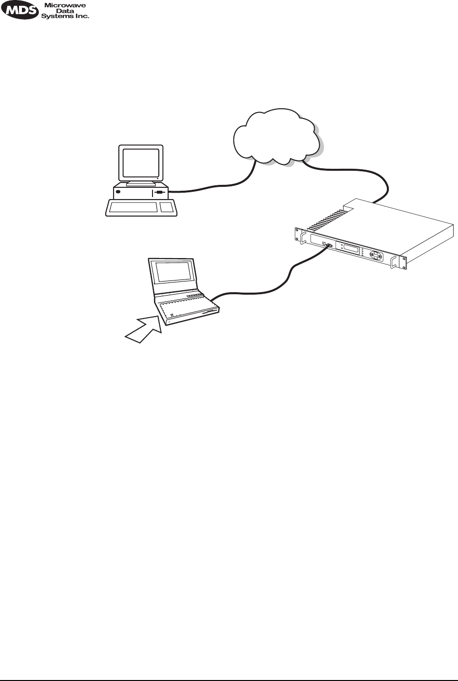
Setup
Connect the LEDR radio’s ETHERNET connector to network which has
a PC connected with the desired LEDR firmware on its hard drive. The
“network” can be a local area network, a wide-area network or any IP
network that can connect the two units.
98 LEDR Series Installation & Operation Guide MDS 05-3627A01, Rev. C
The computer hosting the firmware image, must be running a TFTP
server software. If not, install, launch and configure the MDS TFTP
Server software found on the LEDR Utilities disk. The setup configura-
tion is shown in Figure 19.
Invisible place holder
Figure 19. Uploading firmware from a remote server via Ethernet
Download Procedure
1. Start a terminal program, such as HyperTerminal, on the local PC.
2. Log into the LEDR radio using the login command.
3. Use the ip command to ensure that the radio has a valid IP address.
4. Use the ping command from the local PC to ensure that the PC and
the radio have valid routes to pass information between them.
5. At the radio’s LEDR> prompt, start the download by entering repro-
gram network [filename] [source PC’s IP Address]. The download can be
monitored from the radio by entering reprogram status. When the
download is complete the radio will sound two short beeps and the
response from reprogram status will indicate that the download has
finished.
TFTP
SERVER ETHERNET
PORT
9-PIN SERIAL
CABLE
CONSOLE PORT
(DCE)
INITIATE UPLOAD
FROM HERE
LEDR RADIO UNIT
REMOTE PC
W/FIRMWARE FILES HUB/LAN/WAN/MAN
TCP/IP
ETHERNET
PORT
COM1, 2, ETC.
(DTE)
TERM
PROG.
LEDR> REPROGRAM NETWORK FILENAME.MPK 192.168.X.B
(CHECK STATUS: LEDR> REPROGRAM STATUS)
IP ADDRESS: 192.168.X.B
IP ADDRESS: 192.168.X.W
LOCAL WINDOWS PC

MDS 05-3627A01, Rev. C LEDR Series Installation & Operation Guide 99
SNMP Option The TFTP download process can also be initiated using an SNMP man-
ager. The Firmware|FwProgTable object provides a means for specifying
the TFTP server IP address and the filename for the firmware.
Verification and Reboot
When the download is complete, verify the firmware image and reboot
the radio as described under Verification and Reboot in Paragraph See
“Verification and Reboot” on Page 95 for the procedure.
9.0 USING ORDERWIRE
9.1 Introduction
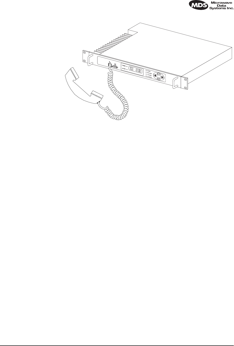
A handset may be plugged into the front panel of the LEDR radio to
allow voice communications between radio sites (see Figure 20). This
can be especially useful during setup and service of the radio equipment.
All radios on the network can hear what is said by any individual
speaking into a handset. No other radio may transmit on the orderwire
until the current speaker is finished. Depending on the number of hops,
the link data rates, and Interleave setting, there may be a noticeable
latency from one end of the network to the other.
The front panel alert function (See “Unit ID” on Page 34) and alert com-
mand (Page 51) can be used to signal all units in the network or a spe-
cific radio.
Normal payload data is not affected by Orderwire use. The Orderwire
uses voice-compression technology that introduces a slight, but notice-
able, delay in Orderwire audio.
The orderwire will not interrupt the normal data flow through the LEDR
data communication channel, however, it will reduce the throughput
efficiency of any data communications on the Service Channel during
periods of voice transmission.
A handset is available from MDS (P/N 12-1307A01), which has a
push-to-talk button and provides basic communication services but does
not contain a built-in DTMF (tone) keypad. (The Orderwire supports the
transmission of DTMF-type signaling by detecting tones at the source,
and regenerating them at the receiving end, however, there are no
DTMF supported radio functions in the LEDR radios.)
9.2 Setup
Program the vox and volume setting for each radio. The volume setting is
user preference. The vox setting requires some forethought. The higher
the vox setting, the louder the user must speak to get the voice decoder
to recognize the speech. This will, however, prevent noise from entering

100 LEDR Series Installation & Operation Guide MDS 05-3627A01, Rev. C
the “line.” A low vox level will recognize speech better but may transmit
more noise with the speech. The user should experiment with the vox
setting to determine the best level for the speaker and the noise environ-
ment.
9.3 Operation
1. Plug the handset into the front panel jack labeled . (Figure 32
on Page 129 provides pinout details for this connector.)
2. Press or at the menu’s top level until Orderwire appears on
the LCD display. Press to move to the lower levels of the menu.
3. To call a specific radio station, enter the Unit ID number for the sta-
tion to be called. (At this point, an alert signal (“ring”) will be sent
to earpiece of the handset connected to the “called” station.
4. Press the PTT on handset to speak to the other station(s) listening to
their handsets connected to LEDR equipment on the network.
Release the handset PTT to listen. VOX (voice-activated transmit)
operation is also supported. (See “vox” on Page 88.)
5. Alternatively, a DTMF-style handset can be used to “dial” the
required radio station.
6. Remember, regardless of the number of users, only one may speak
at a time.
NOTE: The LEDR radio has a built-in DTMF decoder in the orderwire
circuitry. If a standard DTMF telephone test set is plugged into
the orderwire, the user can dial in the three digit unit address
on the handset to “ring” the earpiece of the handset of the asso-
ciated LEDR unit.The LEDR chassis will not provide power to
ring a standard bell or electronic ringer.
ENTER
MDS 05-3627A01, Rev. C LEDR Series Installation & Operation Guide 101
Invisible place holder
Figure 20. Orderwire Connection
9.4 Related NMS Commands
The orderwire can be configured by the NMS commands or through the
front panel. The earpiece volume is more easily set by the front panel
controls as the level is dependent on personal preference.
vox – Voice level (relative) at which speech will be detected by the soft-
ware (See “vox” on Page 88)
volume – Sets/displays the handset volume (See “volume” on Page 88)
alert – Sends an orderwire alert to a specific radio or to all the radios on
the network (See “alert” on Page 51)
10.0 USING THE SERVICE CHANNEL
10.1 Concept
The Service Channel sends and receives ASCII-based information at
9600 bps in a half-duplex broadcast mode throughout the network. This
means that any data coming through the Service Channel Port of a radio
will be broadcast to the Service Channel of each radio in the network.
There can be only one radio transmitting Service Channel data over the
network at a time and the data will always be sent to every radio on the
network. No other radio will be allowed to transmit until the current
sender is finished.

102 LEDR Series Installation & Operation Guide MDS 05-3627A01, Rev. C
If a radio does receive data in the Service Channel Port while another
radio is the active-sender, the data coming in the port will be queued and
sent when the active sender is finished. Depending on the number of
hops, link data rate, and Interleave setting, there may be a noticeable
latency from one end of the network to the other.
10.2 Setup
The user can configure all the Service Channel parameters for a specific
radio. The port may be enabled or disabled. In the disabled state (svch
port off), any data that comes in the Service Channel port will be dis-
carded and any Service Channel data that comes into the radio from
another radio in the network will be passed along to the rest of the net-
work but not sent out the Service Channel Port. When the Service
Channel Port (svch port on) is enabled, it will behave based on the other
settings.
The most important setting is the echo parameter. Echo is used with a
terminal emulator on a PC and the program does not display on the
screen character keyed in by the user.
When you set up a system, you must be careful to avoid an infinite loop.
If echo is enabled, then every character that enters the Service Channel
port will be echoed back out the port. When echo is disabled then data
that comes in the Service Channel port is not sent back out the port.
Trouble may arise if the device that is connected to the Service Channel
also echoes the data it sends. In that case, the device will send characters
into the Service Channel Port, the radio will echo the characters back to
the device, the device will consider the echoed data to be input which it
will in turn echo back to the radio, etcetera, until an overflow condition
occurs.
You must also set the communication parameters (baud rate, stop bits,
char length, and parity) via the svch subcommands so that the settings
match those at the device connected to the Service Channel Port.
Lastly, the user can re-initialize the Service Channel port via the svch
reset command. This may be helpful in the case where an infinite loop
overflow condition has locked the port.
10.3 Usage
The Service Channel supports ASCII data transfer over the network in
broadcast fashion. As a result, devices connected to the Service Channel
Ports of different radios will appear to have a transparent half-duplex
connection between them.

MDS 05-3627A01, Rev. C LEDR Series Installation & Operation Guide 103
10.4 NMS Commands
This command is used to set/display Service Channel parameters.
Usage: svch [subcommand] [<argument>]
Subcommands: baud
char
echo
off
off
on
parity
reset
stop
on—Enable the Service Channel
off—Disable the Service Channel
reset—Re-initialize the Service Channel
echo—on/off
baud—300, 600, 1200, 2400, 4800 and 9600
char— 5, 6, 7, 8 (ASCII character length in bits)
parity—none, even, odd
stop—1, 2 (Stop bits)
11.0 PROTECTED CONFIGURATION
11.1 Introduction
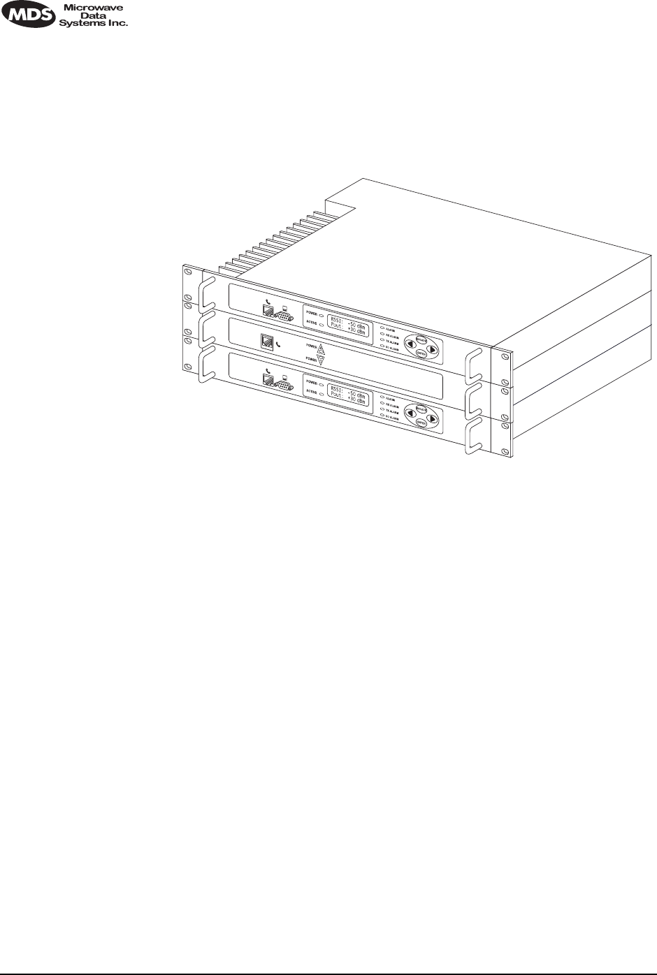
The LEDR radio can be supplied in a protected (also called redundant
or “1+1”) configuration (Figure 21). The protected version is designed
to perform automatic switchover to a second radio in the event of a
failure in the primary unit.
Protected operation is important for many mission-critical or revenue
producing links. By configuring two identical LEDR radios in parallel
and including a third switch box containing the RF switching circuits
and the customer interfaces, it is possible to protect against failure in any
of the LEDR radio sub-systems. Failures can be either malfunction or
external environmental effects, such as multipath fading or nearby light-
ning strikes.
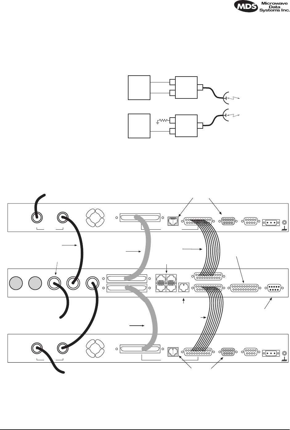
A Protected station consists of two standard LEDR Series radios and a
Protected Switch Chassis (center unit in Figure 21). Ordinarily, the three
chassis are mounted together in a “stacked” arrangement, one above the
other, as shown in the figure.
104 LEDR Series Installation & Operation Guide MDS 05-3627A01, Rev. C
The top unit is referred to as the system’s “Unit A”, and the lower one
as “Unit B”. Each unit is considered to be the “sibling” of the other. The
sibling of Unit A is Unit B, and the sibling of Unit B is Unit A. This dis-
tinction is used in the rdnt command found on Page 74 under the sub-
heading “Read & Write Commands.”
Invisible place holder
Figure 21. LEDR Radio Protected Version
The front panel of the Protected Switch Chassis (PSC) front panel has
only two LEDs and an RJ-45 jack for an orderwire handset. The LEDs
indicate by light and an arrow outline which LEDR chassis is active. It
is assumed the two LEDR chassis will be mounted above and below the
PSC as shown in Figure 21.
11.2 Protected Operation
During normal operation, one radio path is selected and the RF and
interface switches are set to service that path. (The illuminated POWER
LED indicator on the front panel of the Protected Switch Chassis (PSC)
points to the currently active unit.) A switch in the transmitter circuitry
allows one transmitter to be connected to the common ANTENNA port on
the Protected Switch Chassis. On the receive path, a splitter in the Pro-
tected Switch Chassis allows both radio receivers to receive the
incoming RF signal for processing.
The Protected Switch Chassis is a gateway for data coming and going
between each of the LEDR radio units and the common data circuits
connected to the PSC. The PSC monitors various RF and data signal
paths for predefined fault-determining parameters. If signal conditions
are not normal, the PSC’s microprocessor controller will issue an alarm
and move the standby LEDR radio to the active mode.
UNIT A
UNIT B
PSC

MDS 05-3627A01, Rev. C LEDR Series Installation & Operation Guide 105
Fault-determining parameters can be programmed from the Network
Management System (NMS) software. Examples of these parameters
are:
• Low transmitter power
• High transmitter temperature
• Synthesizers is out-of-lock
• Problem with the option board or framers
• CPU failure wherein the CPU watchdog causes a reset
• Fan fault
Transmitter Failure
Any failure on the “active” transmitter path will create a fault condition
which will place the currently the active transmitter on standby and
switch the “standby” transmitter to “active.” The newly active transmit
path will remain in use until a manual changeover returns the configu-
ration to the original transmitter path. This allows the link to remain
fully operational until the user has replaced the faulty transmitter cir-
cuitry.
Receiver Failure
Both receivers are fed via an RF splitter from the antenna port. Each RF
path is buffered and monitored for receive signal integrity for uncorrect-
able bit-errors. If the “active” receive circuitry fails, uncorrectable
bit-errors will be detected. The modem receive switch will first deter-
mine that the “standby” receive path is operational (no uncorrectable bit
errors) and will switch accordingly.
11.3 Configuration Options
The protected LEDR radio is available with a number of configuration
options, each designed to optimize particular system solutions:
1+1 Operation—Warm or Hot Standby
In a warm standby link, the standby transmitter is powered down. In a
hot standby link, the standby transmitter is powered up and transmitted
in a dummy load. The warm standby option offers the advantages of sig-
nificantly reduced power consumption, since only one transmitter path
is powered. However, upon transmitter failure, the switchover takes
longer due to the transmitter having to be powered. Thus the hot standby
mode offers the advantages of faster switchover time and increased
overall system availability.
106 LEDR Series Installation & Operation Guide MDS 05-3627A01, Rev. C
Symmetrical or Asymmetrical Receiver Splitters
The default protected radio is configured with a 3 dB splitter on the
receive path, meaning that each radio’s receiver signal level is equal, but
typically 4dB worse than an unprotected radio (3 dB due to splitter, plus
dB cabling and additional connectors). As an option, an asymmetrical
splitter (1 dB / 10 dB) is offered. Using this option, the active path is 2
dB stronger than with a symmetrical splitter (1 dB compared to 3 dB
splitter loss), allowing for a better fade margin and increased system
availability during normal operation.
However, upon receiver change over, the receive signal strength will be
significantly reduced due to the 10 dB of splitter loss rather than the
equal splitter’s 3 dB loss, making the link more sensitive to fading in this
temporary switched state. Providing the failed standby receiver is
replaced within a short period of time, many users find that the asym-
metric splitter’s increased normal performance offsets any deterioration
in the temporary switched state.
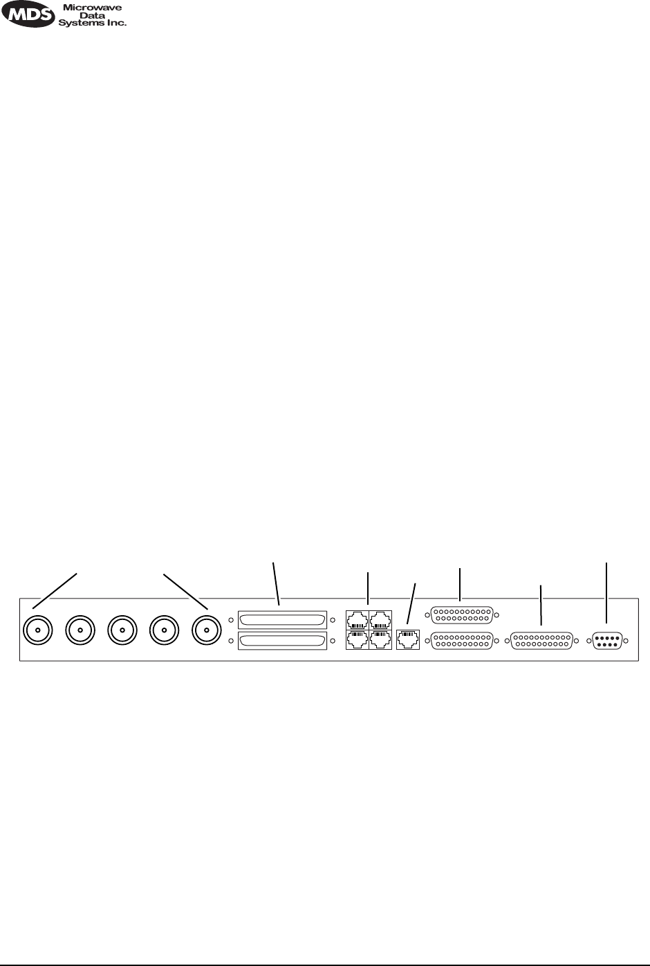
11.4 PSC Rear Panel Connectors
The following are descriptions of the rear panel connections of the Pro-
tected Switch Chassis. The PSC’s rear chassis is shown in Figure 22.
Figure 21 presents an inter-unit cabling diagram for protected configu-
rations.
Invisible place holder
Figure 22. Protected Switch Chassis—Rear Panel
RxA
The RXA (Receive—Radio A) connector is a N-type coaxial connector.
It connects to the RX port on the rear panel of Radio A via a short coaxial
cable.
RxB
Same as RXA, but for Radio B.
Antenna
The ANTENNA connector is a N-type coaxial connector. It serves as the
connection point for the station antenna.
TxBAntenna TxARxBRxA 530 (A&B) EIA-530-A Service ChannelEthernetE1Protected
12
34
B
A
ETHERNET
SERVICE CHANNEL
RF CONNECTORS E1 DATA
PROTECTED DATA 530 (A&B)
EIA-530-A

MDS 05-3627A01, Rev. C LEDR Series Installation & Operation Guide 107
TxA
The TXA (transmit, radio A) connector is a N-type coaxial connector. It
connects to the TX port on the rear panel of Radio A via a short coaxial
cable.
TxB
Same as TXA, but for Radio B.
Protected (Data)
This pair of connectors accepts G.703 signals from each of the LEDR
radios. The top connector is for Radio A, and the bottom connector is for
Radio B. For pinout information, see Figure 36 on Page 130.
E1
This is a block of four RJ-45 modular connectors for connection to a
multiplexer or other customer-supplied E1 equipment. For detailed pin
information, Figure 34 on Page 130.
These connectors are not operational on “S” Series (Subrate) radios.
Ethernet
The ETHERNET connector provides access to the embedded SNMP
agent and other elements of the TCP/IP network management system.
The connector is a standard 10 Base-T connection with an RJ-45 mod-
ular connector. For detailed pin information, see Figure 34 on Page 130.
530 (A&B)
This pair of DB-25 connectors accepts EIA-530 data signals from each
of the LEDR radios. The top connector is for Radio A, and the bottom
connector is for Radio B. For pinout information, see Figure 36 on
Page 130.
EIA-530-A
This DB-25 connector provides a connection point for customer-sup-
plied EIA-530 data equipment. Note: This port is not operational in full-
rate models.
Service Channel
In a protected configuration, this DB-9 connector becomes the Service
Channel connection for both LEDR radios. (In the protected radio con-
figuration, the Service Channel connectors on the radios are non-func-
tional.) For detailed pin information, see “Service Channel—Rear
Panel” on Page 131.
108 LEDR Series Installation & Operation Guide MDS 05-3627A01, Rev. C
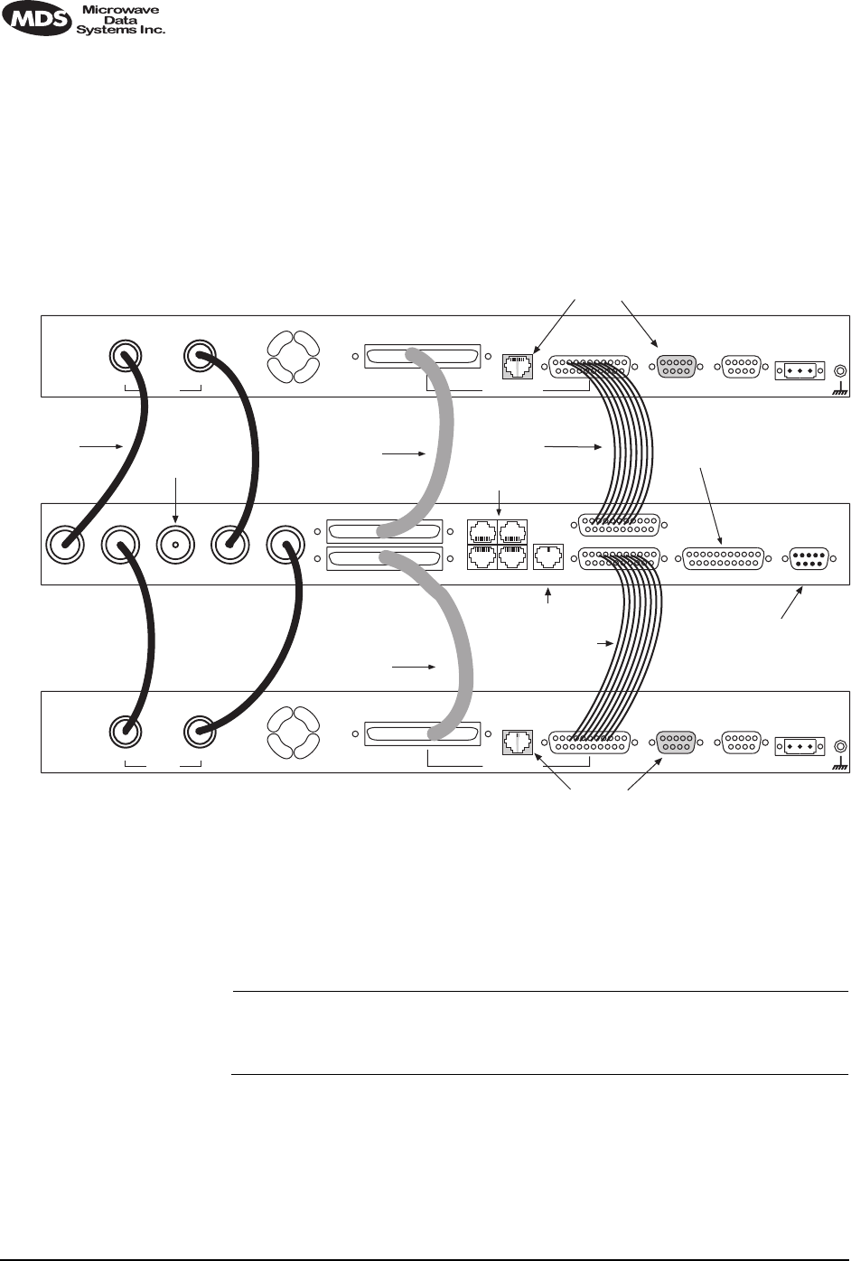
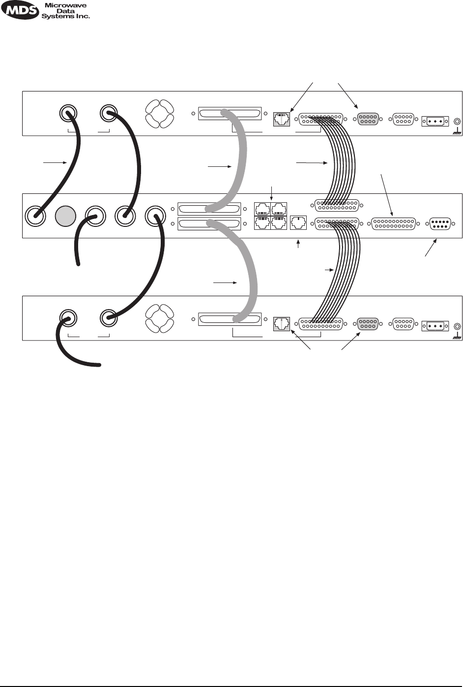
11.5 Inter-Unit Cabling for Protected Stations
The required cabling between the two radios and the Protected Switch
Chassis is dependent on the data interface, unit type (subrate versus
full-rate), and transmit and receive antenna configuration.
The cabling for a pair of standard radios with internal duplexers is
shown in Figure 23.
Figure 23. Inter-unit Cabling—Protected Version
with Internal Duplexers
11.6 Configuration Commands for a Protected
System
NOTE: In a protected link configuration, ensure that the E1/T1 inter-
face settings are identical for both radios at a each end of the
link.
Once the inner-chassis cabling is in place and the units are powered up,
several parameters are required to place the LEDR radio into proper
operation as a member of a protected system.
The tasks involved are reviewing and setting up of the following param-
eters:
DO NOT USE IN
PROTECTED CONFIG.
TxBAntenna TxARxBRxA 530 (A&B) EIA-530-A Service ChannelEthernetE1Protected
TX
External Data Interface
EIA-530-A
Ethernet
NMS
Service
Channel Alarm I/O DC Power Input
EIA-530-A
Ethernet
NMS
Data Interface
Service
Channel Alarm I/O DC Power Input
TO
STATION
ANTENNA
12
34
TO
MUX OR OTHER
E1 EQUIPMENT
TO ETHERNET HUB
TO EIA-530
DATA EQUIPMENT
(SUBRATE MODELS)
SERVICE CHANNEL
(SERVES BOTH RADIOS)
RX
COAXIAL CABLES (4)
P/N 19-1323A02 CABLE 1A
P/N 03-3837A01
TX
External
RX
G.703/Expansion Data
G.703/Expansion Data
RADIO A
RADIO B
PROTECTED SWITCH
CABLE 2B
P/N 03-3828A01
(SUBRATE MODELS)
CABLE 1B
P/N 03-3837A01
DO NOT USE IN
PROTECTED CONFIG.
CABLE 2A
P/N 03-3828A01
(SUBRATE MODELS)

MDS 05-3627A01, Rev. C LEDR Series Installation & Operation Guide 109
•Radio Operation
•General
•Redundant Specific
•Data Interface
•Subrate—Fractional-T1
•Fullrate—E1/T1
Redundant Specific Parameters
There are several parameters that must be set to enable proper operation
of a protected station. These are all covered under the rdnt command
found on Page 74.
Sample Redundant Configuration Session
The following is a example of a session used to configure a LEDR radio
to serve in a protected system. This sequence will need to be repeated
for each radio in the protected pair.
1. Configure the protected mode to hot-standby:
LEDR> rdnt mode 1
rdnt {mode}: 1+1 Hot Standby
LEDR>
2. Configure the IP address of each radio:
LEDR> ip address 192.168.1.1
ip {netmask}: (255.255.0.0)
ip {gateway}: (0.0.0.0)
ip {port}: (ETH)
ip {address}: 192.168.1.1
ip {netmask}: 255.255.0.0
ip {gateway}: 0.0.0.0
ip {port}: ETH
ip: A reboot is strongly recommended. Do you wish to reboot? (y/n) >y
LEDR>
3. Configure the sibling IP address of each radio:
LEDR> rdnt ip 192.168.1.2
redundant {ip}: 192.168.1.2
LEDR>
4. Configure the hitless switching. (Note that the default is on.):
LEDR> rdnt hitless on
rdnt {hitless}: on
LEDR>
5. Configure the temperature (°C) threshold:
LEDR> rdnt temp 100
rdnt {temp}: 100
LEDR>

110 LEDR Series Installation & Operation Guide MDS 05-3627A01, Rev. C
Transmit Clock Selection (Subrate Models Only)
The transmit clock selection must be addressed for every radio in a sub-
rate radio system installation. The single most important consideration
is that there be only one master clock in a subrate radio network. The
master clock can originate from the radio or from the Customer Pre-
mises Equipment (CPE).
The radio is capable of several different clocking modes. Refer to
Figure 24 on Page 111 for typical system clocking methods.
Refer to the Clock Mode screen description on Page 35 for setting the
radio transmit clocking from the front panel. Refer to the clkmode
description on Page 56 for setting the radio transmit clocking mode from
the CONSOLE Port.
NOTE: When customer premises equipment (CPE) is operated in
looped clock mode, it is recommended that the radio not be set
to line clock mode. To do so may cause the transmitting
radio’s PLL to be pulled out-of-lock, especially when oper-
ating at 4E1 data rates.
MDS 05-3627A01, Rev. C LEDR Series Installation & Operation Guide 111
Invisible place holder
Figure 24. Typical Repeater Clocking Arrangement
(no multiplexer at repeater site)
CPE
REPEATER NULL-MODEM
DATA INTERCONNECT CABLE
ETHERNET CROSS-CABLE
REPEATER SITE
CPE
SITE A
SITE B
SITE C
LEDR Radio
Clock Source: Remote
LEDR Radio Clock
Source: Line 1, 2, 3, 4
LEDR Radio
Clock Source: Remote
Network or
Internal Clock
Looped Clock
Mode
Scenario 1:
LEDR Radio Clock
Source: Internal
Scenario 2:
Scenario 1:
Scenario 2:
Looped Clock
Mode
LEDR Radio Clock
Source: Line 1, 2, 3, 4

112 LEDR Series Installation & Operation Guide MDS 05-3627A01, Rev. C
12.0 SPACE DIVERSITY OPERATION
12.1 Introduction
Space diversity operation is an effective mechanism of increasing a
radio link’s resilience to transmission impairments such as multipath
fading or frequency selective fading. In difficult transmission environ-
ments such as over highly reflective and moving water paths, or in arid
environments where atmospheric ducting occurs, space diversity is the
most effective way of maintaining a continuous radio link.
In a space diversity link, two radio receivers are operated in parallel,
from two separate antennas mounted several wavelengths apart verti-
cally on the antenna tower. The separation of antennas is such that when
one antenna experiences fading due to multi-path interference, the other
antenna, being several wavelengths away, is not likely to experience the
same fade. Thus, one receive path may experience uncorrectable errors,
while the other path will be error free. Similar to the protected operation,
the receive modem switch will determine which buffered data path is
operating with the highest integrity, and select that path without
inducing any additional bit errors into the link.
Space diversity is especially effective in changeable multi-path environ-
ments such as over tidal water paths. Since water is highly reflective,
there will be continual “constructive” and “destructive” interference at
each single antenna over the course of the day as the water rises and falls
and the reflected water path interferes with the line-of-sight path. By
correct vertical positioning of the antennas, these effects can be negated,
allowing one antenna to see a good signal while the other is experi-
encing fading, and the modem switching accordingly to allow the link
to operate error- free.
The space diversity LEDR radio is available only in a hot standby con-
figuration.
12.2 User Interface & Control
Protected operation is configured using the Redundant screen (Page 41)
on either radio front panel, or with the rdnt command from a NMS ter-
minal (see Page 74).
12.3 Transmit Clock Selection
There is no difference between a space diversity system and redundant
radio arrangements with respect to transmit clock selection. Fullrate
radios require no user intervention for clocking. Users of subrate sys-
tems should set the radio clocks as described for subrate systems. See
“Transmit Clock Selection” on Page 112 for further information.
MDS 05-3627A01, Rev. C LEDR Series Installation & Operation Guide 113
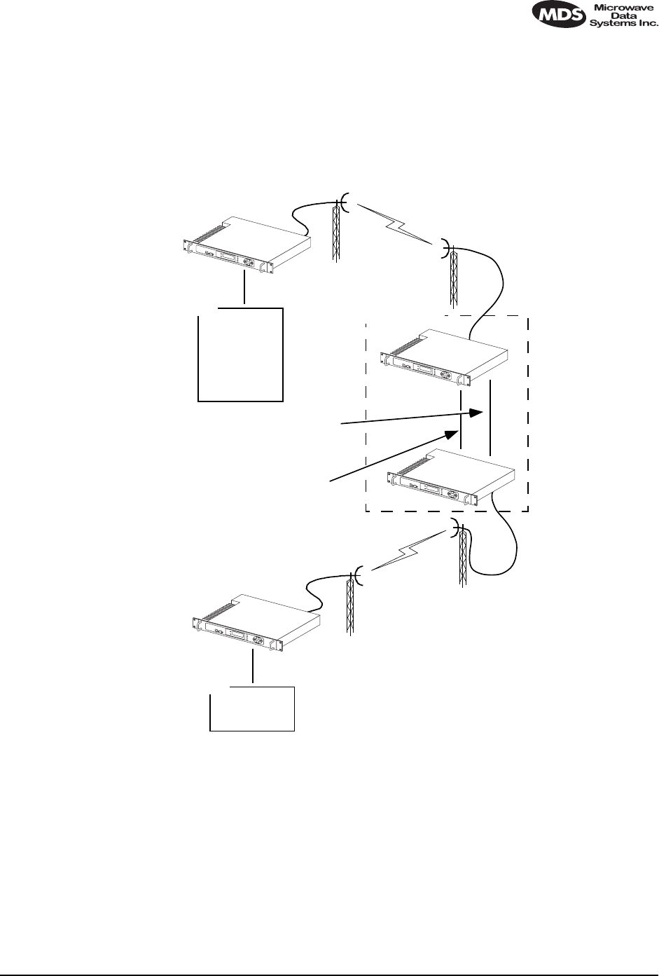
12.4 Inter-Unit Cabling for Space Diversity Stations
The RF cabling for space diversity stations depends on the location of
the duplexers. The block diagram in Figure 25 shows the RF connec-
tions in a typical system with two external duplexers.
Invisible place holder
Figure 25. Block Diagram of a Space Diversity Station
with External Duplexers
The inter-unit cabling for a space diversity system with external
duplexers is shown in Figure 26.
Figure 26. Inter-unit Cabling—Space Diversity
with External Duplexers
TX
RX
ANT
RX
TX DUPLEXER
A
TX
RX
ANT
RX
LEDR
UNIT B DUPLEXER
B
LEDR
UNIT A
DO NOT USE IN
PROTECTED CONFIG.
TxBAntenna TxARxBRxA 530 (A&B) EIA-530-A Service ChannelEthernetE1Protected
TX
External Data Interface
EIA-530-A
Ethernet
NMS
Service
Channel Alarm I/O DC Power Input
EIA-530-A
Ethernet
NMS
Data Interface
Service
Channel Alarm I/O DC Power Input
12
34
TO
MUX OR OTHER
E1 EQUIPMENT
TO ETHERNET HUB
TO EIA-530
DATA EQUIPMENT
(SUBRATE MODELS)
SERVICE CHANNEL
(SERVES BOTH RADIOS)
RX
COAXIAL CABLES (2)
P/N 19-1323A02 CABLE 1A
P/N 03-3837A01
TX
External
RX
G.703/Expansion Data
G.703/Expansion Data
RADIO A
RADIO B
PROTECTED SWITCH
CABLE 2B
P/N 03-3828A01
(SUBRATE MODELS)
CABLE 1B
P/N 03-3837A01
DO NOT USE IN
PROTECTED CONFIG.
CABLE 2A
P/N 03-3828A01
(SUBRATE MODELS)
TO
ANTENNA
SYSTEM
TO RX PORT OF
DUPLEXER A
TO RX PORT OF
DUPLEXER B
TO TX PORT OF
DUPLEXER A
114 LEDR Series Installation & Operation Guide MDS 05-3627A01, Rev. C
The inter-unit cabling for a space diversity system with internal
duplexers is shown in Figure 27.
Figure 27. Inter-unit Cabling—Space Diversity
with Internal Duplexers
DO NOT USE IN
PROTECTED CONFIG.
TxBAntenna TxARxBRxA 530 (A&B) EIA-530-A Service ChannelEthernetE1Protected
TX
External Data Interface
EIA-530-A
Ethernet
NMS
Service
Channel Alarm I/O DC Power Input
EIA-530-A
Ethernet
NMS
Data Interface
Service
Channel Alarm I/O DC Power Input
12
34
TO
MUX OR OTHER
E1 EQUIPMENT
TO ETHERNET HUB
TO EIA-530
DATA EQUIPMENT
(SUBRATE MODELS)
SERVICE CHANNEL
(SERVES BOTH RADIOS)
RX
COAXIAL CABLES (4)
P/N 19-1323A02 CABLE 1A
P/N 03-3837A01
TX
External
RX
G.703/Expansion Data
G.703/Expansion Data
RADIO A
RADIO B
PROTECTED SWITCH
CABLE 2B
P/N 03-3828A01
(SUBRATE MODELS)
CABLE 1B
P/N 03-3837A01
DO NOT USE IN
PROTECTED CONFIG.
CABLE 2A
P/N 03-3828A01
(SUBRATE MODELS)
TO RX ANTENNA
SYSTEM
TO TX/RX ANTENNA
SYSTEM A

MDS 05-3627A01, Rev. C LEDR Series Installation & Operation Guide 115
13.0 SPARE PARTS, UNITS AND
ACCESSORIES
13.1 Spares
Spare assemblies and units used for repair of LEDR radios are listed in
Table 28. Field servicing, or replacement of PC boards and assemblies,
should only be performed by qualified service personnel.
When ordering parts from the factory, always give the complete model
number of the radio as found on the serial number label on the chassis.
Contact information can be found on Page 140 of this guide.
Table 28. Field Replaceable Units for LEDR Radios
Item Model Part
Number
Transceiver’s SRAM Power Back-up Battery All Models 27-3109A01
Protected Switch Chassis (Complete unit) LEDR 400F 03-3873A01
LEDR 900F 03-3873A02
LEDR 1400F 03-3873A03
Duplexer (If equipped) All Models Frequency
dependent;
Contact
factory.
FT1 Data Interface PCB LEDR 900S 03-3846A01
E1/FE1 Data Interface PCB LEDR 400F
LEDR 400S
LEDR 900F
LEDR 900S
LEDR 1400F
LEDR 1400S
03-3846A02
Subrate Data Interface PCB LEDR PSC 03-2824A01
Fullrate Data Interface PCB LEDR PSC 03-3539A01

116 LEDR Series Installation & Operation Guide MDS 05-3627A01, Rev. C
13.2 Accessories
Table 28 lists accessories available from the factory as a convenience to
our customers. Factory contact information can be found on Page 140 of
this guide.
Table 29. Accessory Items for LEDR Radios
Item Description Part
Number
V.35 Interface Cable 6 ft (1.8 m) cable adapter used to convert
subrate LEDR radio EIA-530 data
interface to V.35 male data interface.
03-2174A01
G.703 Balun Miniature G.703 balun used to convert a
fullrate LEDR radio’s 120 Ω balanced
data interface to two 75 Ω BNC coaxial
data interfaces.
One balun required per E1 port.
01-3494A01
EIA-530 Null-MODEM
Crossover Cable 6 ft (1.8 m) cable adapter to connect
subrate interfaces in a repeater
configuration.
97-2841L06
SNMPc™ Network
Management Manager SNMP Management Software to access
the LEDR embedded SNMP agent,
allowing management of the LEDR radio
network and any interconnected SNMP
enabled peripherals.
For Windows 95 O/S
03-3530A01
SNMPc™ Network
Management Manager SNMP Management Software to access
the LEDR embedded SNMP agent,
allowing management of the LEDR radio
network and any interconnected SNMP
enabled peripherals.
For Windows 98 or NT O/S.
03-3530A02
Orderwire Handset Voice handset with 4-wire cord (RJ-11
modular plug). 12-1307A03
Orderwire Handset Kit Voice handset with 4-wire cord (RJ-11
modular plug), hanger and mounting
bracket.
02-1207A01
AC Power Adapter External AC power supply provides 24
Vdc to LEDR radio.
Input: 110 Vac to 240 Vac, 50 to 60 Hz
03-3862A01

MDS 05-3627A01, Rev. C LEDR Series Installation & Operation Guide 117
14.0 FRACTIONAL-T1 INTERFACE
CARD 03-3846A01
FRACTIONAL-E1 INTERFACE
CARD 03-3846A02
14.1 Introduction
The Fractional-T1 (FT1) and Fractional-E1 (FE1) Interface cards are
optional assemblies which provide additional connectivity within a
LEDR network for all subrate (S) models. The installation of the
FT1/FE1 Interface card inside the radio allows the standard EIA-530
customer data interface to be bypassed and the radio data lines to be con-
nected directly to a G.703 T1 or E1 interface.
With the optional FT1/FE1 Interface, users are able to place a LEDR
link from a network service access point to a remote site, where an
installation supports multiple communications devices. Direct interface
to customer equipment, such as channel banks, is possible without the
use of expensive protocol converters.
14.2 Fractional-T1/E1 Performance
The FT1 and FE1 Interface allows the LEDR radio to be connected
directly with a G.703 T1 or E1 interface. The line rate of the interface
operates at the T1 rate of 1.544 Mbps, or E1 rate of 2.048 Mbps. Twelve
user selectable DS0 timeslots are transmitted over the air in either case.
The FT1 interface is G.703 at 100 Ω line impedance. The FE1 interface
is G.703 at 120 Ω line impedance. Physical connection is via an RJ-45
jack on the rear panel.
14.3 Configurable Parameters
The following performance specifications of the T1 fractional interface
are adjustable by the user. All of these parameters are manageable
locally, or over the air via SNMP network management. (Refer to the
SNMP Handbook, P/N 05-3532A01 for more information.)
Timeslots and Framing
Twelve DS0 timeslots are permitted. In FT1, the timeslot selection is
arbitrary. In FE1, timeslot 0 is always sent and the remaining timeslots
are arbitrary with the exception of timeslot 16. (Timeslot 16 must be sent
when any CAS frame structures are selected.) The selection of timeslots
can be different at each end of the link, provided their number is equal.
The timeslots may not be reordered.

118 LEDR Series Installation & Operation Guide MDS 05-3627A01, Rev. C
Alarm signals RAI and AIS are generated as appropriate. The user may
optionally have these signals forwarded over the RF link.
The frame formats available for Fractional-T1 operation are as follows:
•FT only
•ESF without CRC checking and generation
•SF (D4)
•SF with JYEL indication
•ESF with CRC checking and generation
The frame formats available for Fractional-E1 operation are as follows:
•FAS only
•FAS with BSLIP
•FAS with CRC
•FAS with CRC and BSLIP
•FAS and CAS
•FAS with CAS and BSLIP
•FAS with CAS and CRC
•FAS with CAS
•CRC and BSLIP.
The re-framing criteria may be adjusted to the following settings: 2 out
of 4 Fbit errors, 2 out of 5 Fbit errors, 2 out of 6 Fbit errors. For FE1, the
reframing criteria is selectable between consecutive FAS errors or CRC
errors.
Line Codes
The following standard T1 line codes are supported: B8ZS, AMI, and
per-channel B7ZS.
The following standard E1 line codes are supported: HDB3 and AMI.
Diagnostics
The T1 line at each end of the link may be tested using a variety of bit
patterns. In normal operation, statistics are stored for any errors occur-
ring at the line interface, such as framing errors, bipolar violations, and
CRC errors.
Data may be looped back at the local port, through the T1 option only,
and at the remote unit. Further, the unit will respond to in-band (SF) and
data link (ESF) loopback codes at the local port.
When in ESF framing mode, the option can automatically generate per-
formance report messages.

MDS 05-3627A01, Rev. C LEDR Series Installation & Operation Guide 119
The following alarms may be monitored & logged. They may also be
associated with a user-selectable indication (alarm contact or front panel
LED): Remote Loopback, Lost Frame, Lost Signal, Lost Analog Signal,
AIS, RAI (RYEL), MultiFrame RAI, Severely Errored Frame, Frame
Re-Align, MultiFrame AIS, Far End Block Error, Line Code Error, CRC
Errors and Frame Bit Error.
Clocking
The clock source is configurable for network, loopback, and internal
timing, with secondary selections available should the primary source
become faulty. Refer to the discussion of the clkmode command
(Page 54) for more information
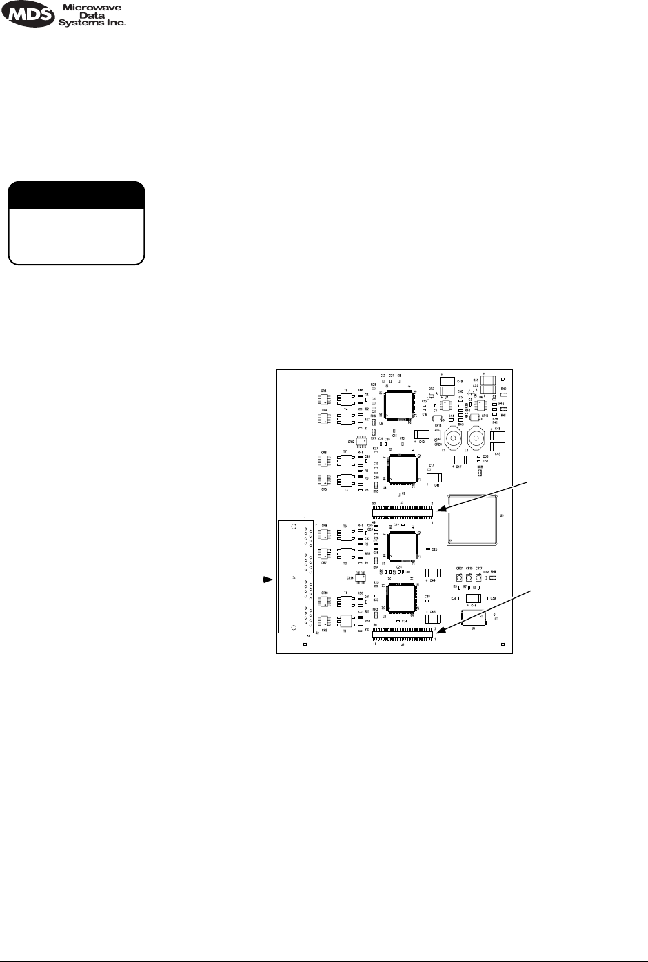
14.4 Field Installation of the FT1 Interface Board
An “S” Series LEDR radio can be fitted with a Fractional-T1 (FT1) or
Fractional-E1 (FE1)Interface Board (Figure 28). The addition of an
FT1/FE1 board enables the radio to operate with a G.703 interface at
speeds up to 768 kbps.
To add the FT1/FE1 Interface Board to an existing LEDR radio trans-
ceiver, follow these steps:
1. Remove the top cover of the radio (4 Phillips screws).
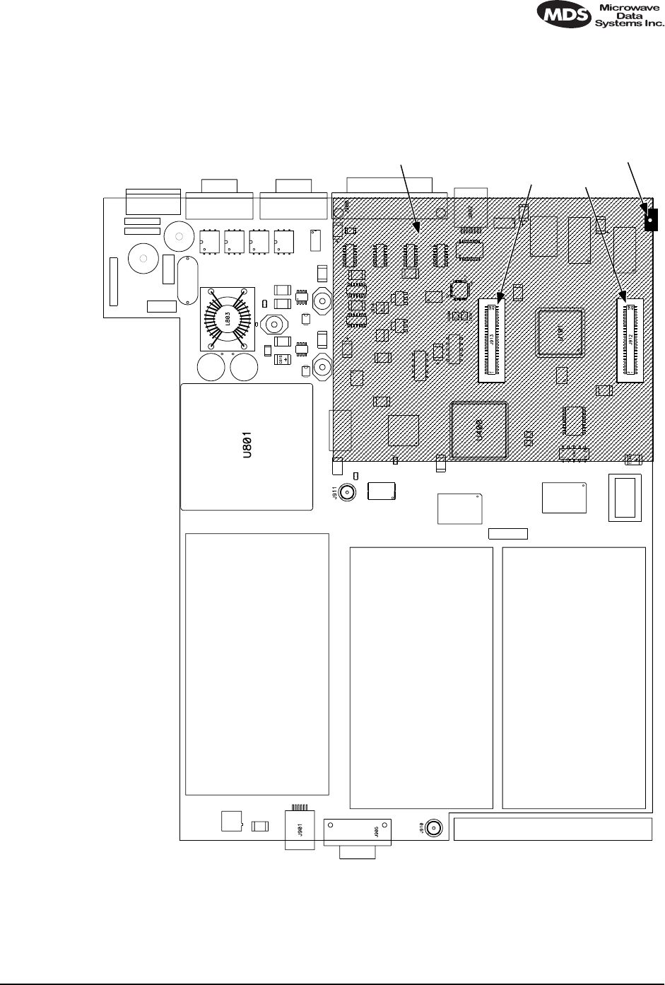
2. Identify the installation area for the Interface Board (See Figure 29).
Remove the three Phillips screws on the main PC board which cor-
respond to the mounting holes on the Interface Board.
3. Install the threaded standoff spacers (furnished with the option
board) onto the main PC board in the holes formerly occupied by the
screws. (Note: Washers must not be used between the standoff spac-
ers and either of the PC boards.)
4. Locate connectors J912 and J913 (See Figure 29). These connectors
mate with the plugs on the bottom of the Interface board.
5. Carefully set the optional board into place, making sure to align the
mounting holes with the threaded standoffs on the main PCB. (The
Interface Board’s rear panel connector should align with the rectan-
gular cutout at the radio’s rear panel, and the rear edge of the option
board should be parallel to the main PC board.)
6. Look under the right edge of the Interface board to ensure that J912
is aligned with the mating connector on the option board. With the
board properly aligned, push down firmly in the area directly above
J913 and then over J912 at the edge. A distinct “locking” action will
be felt as the connectors engage.
120 LEDR Series Installation & Operation Guide MDS 05-3627A01, Rev. C
7. Install the Phillips mounting screws with lockwashers on the top of
the FT1 board.
For protected versions only: Install the plastic clip, if supplied, at the
right rear corner of the Interface board. It slips over the edge of the
main PC board and the option board. Gently tighten the hex screw to
secure the clamp.)
The Interface board must be properly seated onto the LEDR radio’s
motherboard before powering up the radio chassis. Failure to properly
install the board could result in permanent damage to the motherboard
and the optional PCB.
8. Re-install the radio’s top cover. This completes the Interface Board
installation.
Invisible place holder
Figure 28. FT1/FE1 Interface Board—Optional Assembly
(Part No. 03-3846Axx)
CAUTION
POSSIBLE
EQUIPMENT
DAMAGE
User Interface
Ports Mates with J912 on
Radio PC Board
Mates with J913 on
Radio PC Board
MDS 05-3627A01, Rev. C LEDR Series Installation & Operation Guide 121
Invisible place holder
Figure 29. View of Radio PC Board
Showing Installation Details for FT1/FE1 Interface Board
J912J913
REAR PANEL OF LEDR RADIO
Installation Area
for Interface Board
PC Board Clamp
(Some Versions)

122 LEDR Series Installation & Operation Guide MDS 05-3627A01, Rev. C
15.0 INCREASE BANDWIDTH BY
CHANGING TRANSMITTER AND
RECEIVER FILTERS
15.1 Introduction
It is possible for qualified service personnel to upgrade LEDR Series
radios in the field to increase the radios RF bandwidth. Listed in Table
30 are five upgrade kits. Each kit consists of three RF filters; one is used
in the transmitter section and two are used in the receiver section. In
addition, there is a unique software key that will allow the data circuitry
to handle the higher data bandwidth. This key is based on the radio’s
serial number and can only be used with that radio.
Each kit consists of a set of 3 filters (transmitter 1; receiver 2), software
activation key and instructions for converting radio’s occupied band-
width. The radio serial number must be provided to the factory for issue
of authorization key.
To realize the full benefit of the increased RF bandwidth, it may be nec-
essary to upgrade the radio’s data interface. Table 1 on Page 1 provides
a simplified listing of radio bandwidth and compatible data interfaces.
15.2 Filter Removal and Replacement
These instructions describe the removal and replacement of filter mod-
ules inside a LEDR Transceiver, as well as the software commands nec-
essary to authorize the new bandwidth.
CAUTION: This upgrade involves the removal of small, delicate parts.
It must be performed by experienced personnel only, using
proper tools and equipment to preserve the factory warranty.
Precautions must be taken to prevent damage to components
due to static discharge and other risks.
1. Remove the radio from service and disconnect all cabling from the
rear panel.
Table 30. Hardware Upgrade Kits for Increased RF Bandwidth
For Subrate Radios For Fullrate Radio
25 kHz to 50 kHz 500 kHz to 1.0 MHz
25 kHz to 100 kHz 500 kHz to 2.0 MHz
25 kHz to 200 kHz 1.0 MHz to 2.0 MHz
50 kHz to 100 kHz
50 kHz to 200 kHz
100 kHz to 200 kHz
MDS 05-3627A01, Rev. C LEDR Series Installation & Operation Guide 123
2. Remove the top cover of the radio (four Phillips head screws).
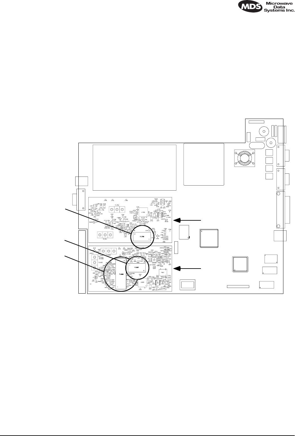
3. Remove the Transmitter and Receiver section’s RF shields
(Figure 30). It will be necessary to unplug the ribbon cables that
cross over the shields—record their locations as you remove them.
4. Locate and remove Filter FL700 from the transmitter section. In its
place, install the replacement filter furnished with the upgrade kit.
Ensure that the new filter is installed in the same orientation as the
original unit.
Invisible place holder
Figure 30. Location of Bandwidth Filters FL600, FL601 and FL700
5. Locate and remove Filters FL600 and FL601 from the Receiver
module. In their place, install the replacement filters furnished with
the upgrade kit. Ensure that the new filters are installed in the same
orientation as the original units.
6. This completes the required hardware changes. Fasten the top cover
and re-connect all cables to the rear panel.
7. Power up the radio and proceed to “Software Commands” below.
LEDR RADIO PC BOARD
FL700
FL601
FL600
Transmitter Section
Receiver Section
124 LEDR Series Installation & Operation Guide MDS 05-3627A01, Rev. C
15.3 Software Commands
To activate the new filter bandwidth, it is necessary to enter an authori-
zation key provided by Microwave Data Systems. This key is based
upon the radio serial number and will authorize the new bandwidth of
the radio. Contact the factory if you do not already have an authorization
number.
1. Initiate a NMS terminal session with the LEDR radio. (Refer to
Page 25 for login details.)
2. At the LEDR> prompt, type: auth add <authorization number>, where
<authorization number> is the number provided to you by the factory.
Press ENTER.
3. This completes the required software changes. If desired, the auth
show command may be entered to display all of the current options
for the LEDR radio.
4. Check for alarms on the front panel LED display. If no alarms are
present, the basic functionality of the radio can be confirmed. If an
alarm is present, double check all cable connections and radio set-
tings.
16.0 BENCH TESTING OF RADIOS
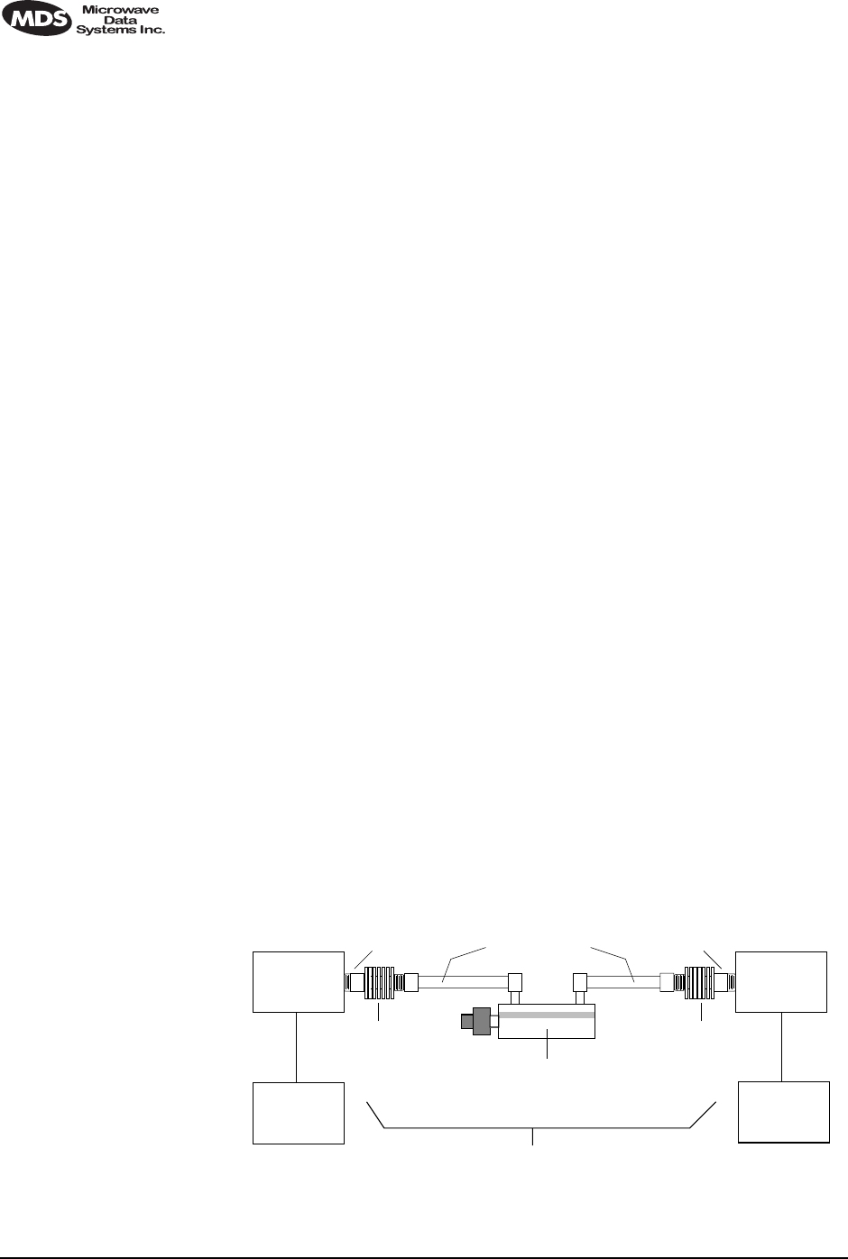
In some cases, it may be necessary to test the operation of the equipment
in a bench setting. Figure 31 shows a simple arrangement for bench
testing using RF attenuators between the two units under test.
For weak signal tests (weaker than –80 dBm), additional physical sepa-
ration between Radio 1 and Radio 2 may be required to prevent uninten-
tional coupling between the radios.
On protected radio configurations, a weak received signal will cause the
radio transceivers to switch.
Figure 31. Back-to-Back Link Test
ANT
Connector ANT
Connector
POWER ATTENUATOR
• 30 dB
• 1W Rating
POWER ATTENUATOR
• 30 dB
• 1W Rating
SWITCHED OR VARIABLE
ATTENUATOR
• 0–110 dB (1 dB Steps)
JFW 50DR-001 or Equivalent
• Required only for receiver sensitivity test.
LOW LOSS COAXIAL LINES
DIGITAL
EQUIPMENT
OR BER
TESTER
RADIO
#1
DATA PORT
TOTAL ATTENUATION
Fixed: 80 dB Minimum for Basic Checks
Adjustable: For Sensitivity Tests (100–140 dB Required)
DIGITAL
EQUIPMENT
OR BER
TESTER
DATA PORT
RADIO
#2

MDS 05-3627A01, Rev. C LEDR Series Installation & Operation Guide 125
You can perform an over-the-air BER test on the bench or in the field.
In this case, attach a separate piece of BER test equipment and feed it
into one or more of the T1/E1 ports. At the other end of the link, you use
another BER test box, or attach a loopback plug to the CPE data I/O
port. This tests the quality of the radio link itself with regard to the user
payload data. Such a bench, or over-the-air, test does not use the LEDR
bert command.
NOTE: It is important to avoid over-driving the receiver as it can be
damaged by strong signals. Signals stronger than -20 dBm
should be avoided to protect the receiver.
NOTE: User BERT test equipment connected to a LEDR T1 data
interface my yield different BERT results than the radio’s ber
command. This is likely when less than the channel's capacity
is utilized by the timeslot command configuration.
17.0 TECHNICAL REFERENCE
17.1 Specifications—
Models: LEDR 400S, LEDR 900S & LEDR 1400S
General
Frequency Ranges: 330–512 MHz (LEDR 400S)
800–960 MHz (LEDR 900S)
1350–1535 MHz (LEDR 1400S)
RF Occupied Bandwidth: 25, 50, 100 and 200 kHz
User Data Rates: 64, 128, 256, 384, 512 & 768 kbps
With optional FT1 Interface Board:
n x 64 kbps (Where n = 12)
Permitted Data Throughput: Channel Size Data Rate
25 kHz 64 kbps
50 kHz 64 kbps to 128 kbps
100 kHz 64 kbps to 256 kbps
200 kHz 64 kbps to 768 kbps
Modulation Type: 32 QAM, 16 QAM, QPSK
Forward Error Correction (FEC): Reed-Solomon
Acquisition Time— Typical: From power up, 10 seconds
Voltage Range: 24 Vdc or 48 Vdc (±20%)
Power Consumption: Less than 60 watts (non-protected configuration)
Temperature Range: – 5° to 50° C
Humidity: ≤ 90% non-condensing @ 40° C
Size: 1 RU; 19 Inch rack mount compatible
45 mm (1.75 in) high, 1RU
426 mm (16.75 in) wide (excluding rack brackets)
305 mm (12 in) deep

126 LEDR Series Installation & Operation Guide MDS 05-3627A01, Rev. C
Transmitter
Transmit Power: +30 dBm (1 watt) at antenna port
Output Control Range: 0 dB to –10 dB
Frequency Stability: 1.5 ppm
Spurious Outputs: < –60 dBc 400S
< –60 dBc 900S
< –60 dBm 1400S
Receiver
Sensitivity (for 10-6 BER): Bandwidth Data Rate Sensitivity
25 kHz 64 kbps –101 dBm
50 kHz 128 kbps –98 dBm
100 kHz 256 kbps –95 dBm
200 kHz 768 kbps –92 dBm
Residual BER: < 1 x 10⁻¹⁰
Dynamic Range: > 65 dB
Interfaces
Data: EIA-530,
G.703 100 Ω, balanced (RJ-45)
with optional FT1 Interface Board
Orderwire: Voice handset interface, DTMF capable
Service Channel: RS-232 @ 9600 bps
Ethernet: 10 Base-T
Console Port: RS-232, 9600 bps to 38.4 kbps
Alarms: 4 programmable outputs; 4 inputs
Antenna: 50 Ω Impedance
Network Management System
Accessibility: Via built-in HTTP server or command line interface
SNMP Management (Optional): Using MIB II and custom enterprise MIB
Diagnostic Functions
Via Front Panel LEDs: Power, Active, General Alarm, Rx Alarm, Tx Alarm
& I/O Alarm
Via Front Panel LCD Display : Measurements of
RSSI, RF Power, Signal-to-Noise ratio, BER
Data Loopback: Local and Remote
Agency Approvals
LEDR 400S EMC: ETS 300 385
LEDR 900S Transmission: FCC Part 101, RS-119
EMC: FCC Part 15

MDS 05-3627A01, Rev. C LEDR Series Installation & Operation Guide 127
LEDR 1400S Transmission: ETS 300 630, MPT 1717
Environmental: ETS 300 019, Class 3.2
EMC: ETS 300 385
Safety: CE Mark
17.2 Specifications—
Models: LEDR 400F, 900F, 1400F
General
Frequency Ranges: 330–512 MHz (LEDR 400F)
800–960 MHz (LEDR 900F)
1350–1535 MHz (LEDR 1400F)
RF Occupied Bandwidth: 500 kHz, 1 MHz & 2 MHz
User Data Rates: 1 x E1 (2.048 Mbps)
2 x E1 (4.096 Mbps)
4 x E1 (8.192 Mbps)
Permitted Data Throughput: Channel Size Data Rate
500 kHz 1 x E1 (2.048 Mbps)
1 MHz 2 x E1 (4.096 Mbps)
2 MHz 4 x E1 (8.192 Mbps)
Modulation Type: 32 QAM, 16 QAM, QPSK
Forward Error Correction (FEC): Reed-Solomon
Acquisition Time (Typical): From power up, 10 seconds
Voltage Range: 24 Vdc or 48 Vdc (±20%)
Power Consumption: Less than 60 watts (non-protected configuration)
Temperature Range: –5° to 50° C
Humidity: ≤ 90% non-condensing @ 40° C
Size: 1RU, 19 Inch rack mount compatible
45 mm (1.75 in) high, 1RU
426 mm (16.75 in) wide (excluding rack brackets)
305 mm (12 in) deep
Transmitter
Transmit Power: +30 dBm (1 watt) at antenna port
Output Control Range: 0 dB to –10 dB
Frequency Stability: 1.5 ppm
Spurious Outputs: < –60 dBc (400F)
< –60 dBm (1400F)
Receiver
Sensitivity (for 10-6 BER): Bandwidth Data Rate Sensitivity
500 kHz 1 x E1 –90 dBm
1 MHz 2 x E1 –87 dBm
2 MHz 4 x E1 –84 dBm
Residual BER: < 10–10
Dynamic Range: > 65 dB

128 LEDR Series Installation & Operation Guide MDS 05-3627A01, Rev. C
Interfaces
Data: G.703 120 Ω, balanced (4 x RJ-45)
Orderwire: Voice handset interface, DTMF capable
Service Channel: RS-232 @ 9600 bps
Ethernet: 10 Base-T
Console Port: RS-232, 9600 bps to 38.4 kbps
Alarms: 4 programmable outputs, 4 inputs
Antenna: 50Ω Impedance
Network Management System
Accessibility: Via built-in HTTP server or command line interface
SNMP Management (Optional): Using MIB II and custom enterprise MIB
Diagnostic Functions
Via Front Panel LEDs: Power, Active, General Alarm, Rx Alarm, Tx Alarm,
I/O Alarm
Via Front Panel LCD Display : Measurements of
RSSI, RF Power, Signal-to-Noise ratio, BER
Data Loopback: Local and Remote
Agency Approvals
LEDR 1400F Transmission: ETS 300 630, MPT 1717
Environmental: ETS 300 019, Class 3.2
EMC: ETS 300 385
Safety: CE Mark
17.3 Specifications—
Protected Switch Chassis
Transmitter Coupling Loss: 2 dB (Typical)
Receive Coupling Losses: 4 dB with Symmetrical Splitter (Typical)
2 dB/10 dB with Asymmetrical Splitter (Typical)
Power Consumption: Less than 135 watts
(Two LEDR radios and Protected Switch Chassis)
17.4 Optional Equipment (Consult factory for details)
• Space Diversity
• Hot-standby Protected
• Warm-standby Protected
• Bandwidth Upgrade Kits
MDS 05-3627A01, Rev. C LEDR Series Installation & Operation Guide 129
17.5 Accessories
• 120/240 Vac 50/60 Hz Power Supply (24 Vdc Output)
• Orderwire Handset
• Other items listed in Table 29 on Page 116
NOTE: The factory reserves the right to make changes to this specification with-
out advance notice or obligation to any person.
17.6 I/O Connector Pinout Information
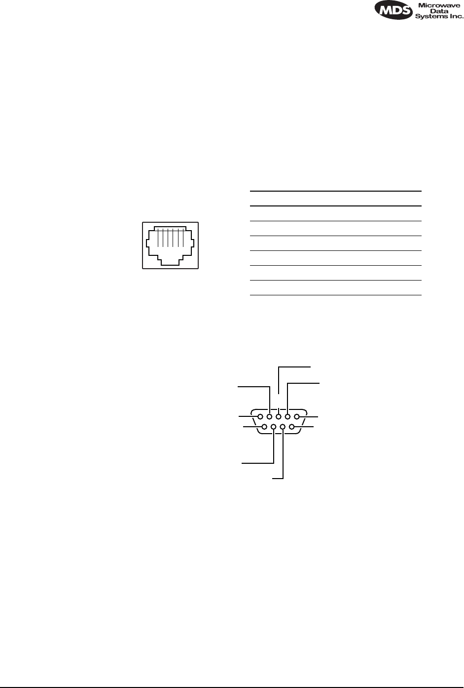
Orderwire—Front Panel Invisible place holder
Figure 32. Orderwire RJ-11 Connector
CONSOLE Port—Front Panel Invisible place holder
Figure 33. CONSOLE Port DB-9 Female Pinout
1 2 3 4 5 6
RJ-45
p
Pin Signal Direction
1 + 12 Vdc Output
2 Ground —
3 Ear –Output
4 Ear + Output
5 Mouth Input
6 Ground —
RJ-11
6
78
9
1
234
5NC
RXD (DATA OUT)
TXD (DATA IN)
NC
NC
NC
NC
NC
GROUND
DCE
130 LEDR Series Installation & Operation Guide MDS 05-3627A01, Rev. C
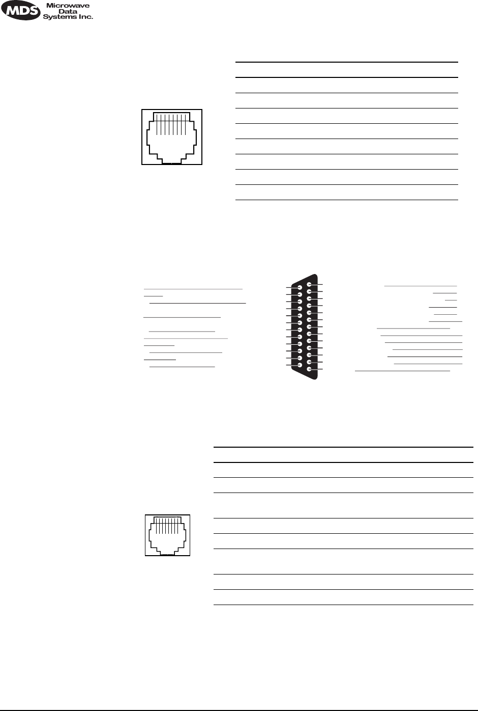
Ethernet—Rear Panel Invisible place holder
Figure 34. Ethernet Connector
EIA-530-A Data—Rear Panel Invisible place holder
Figure 35. EIA-530 Connector Pinout (DB-25)
G.703 Data Connectors (4)—Rear Panel
Invisible place holder
Figure 36. G.703 Data Connector Pinout (RJ-45)
1 2 3 4 5 6 7 8
RJ-45
10Base-T
Pin Signal Direction
1 Ethernet Transmit High Output
2 Ethernet Transmit Low Output
3 Ethernet Receive High Input
4 No Connection —
5 No Connection —
6 Ethernet Receive Low Input
7 No Connection —
8 No Connection —
Clear to Send (B)
Transmit Signal Element Timing (B)
Ext. Transmit Signal Element Timing (B)
13
12
11
10
9
8
7
6
5
4
3
2
1
Received Line Signal Detector (B)
Receiver Signal Element Timing (B)
Received Line Signal Detector (A)
Signal Ground
DCE Ready (A)
Clear to Send (A)
Request to Send (A)
Received Data (A)
Transmitted Data (A)
Shield
Return
Return
Return
Return
Return
DCE
Common
DCE
DCE
DTE
DCE
DTE
Common
25
24
23
22
21
20
19
18
17
16
15
14
Test Mode
Ext. Transmit Signal Element Timing (A)
Common
Remote Loopback
Request to Send (B)
Local Loopback
Receiver Signal Element Timing (A)
Receiver Data (B)
Transmit Signal Element Timing (A)
Transmitted Data (B)
DCE
DTE
Return
DTE
Return
DTE
DCE
Return
DCE
Return
Source
Signal
Designation Pin
No. Pin
No. Signal
Designation Source
Pin Signal Direction
1 Differential digital output signal, ring Output
2 Differential digital output signal, tip Output
3 Ground
(Early models: No Connection) —
4 Differential digital input signal, ring Input
5 Differential digital input signal, tip Input
6 Early models: No Connection
Late models: Ground —
7 No Connection —
8 No Connection —
1 2 3 4 5 6 7 8
RJ-45
MDS 05-3627A01, Rev. C LEDR Series Installation & Operation Guide 131
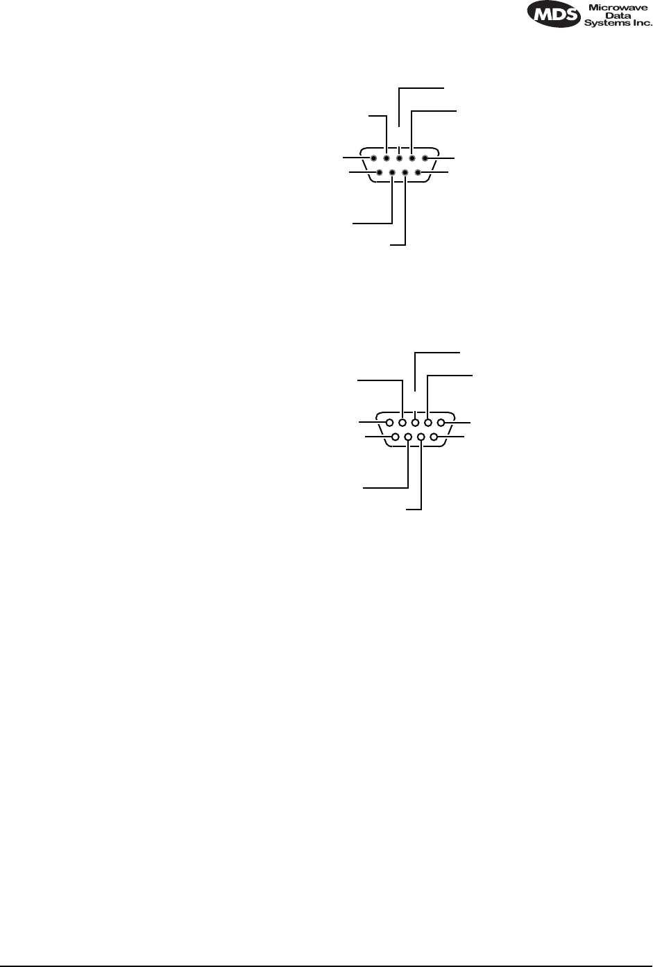
Service Channel—Rear Panel Invisible place holder
Figure 37. Service Channel Connector Pinout (DB-9 Male)
Alarm—Rear Panel Invisible place holder
Invisible place holder
Figure 38. Alarm Connector DB-9 Female Pinout
(See See “Alarm I/O” on Page 20 for parameters.)
6
78
9
1
234
5DCD (IN)
RXD (DATA IN)
TXD (DATA OUT)
DTR (OUT)
DSR (IN)
RTS (OUT)
CTS (IN)
NC
GROUND
DTE
6
78
9
1
234
5ALARM IN 1
ALARM IN 2
ALARM IN 3
ALARM IN 4
ALARM OUT 1
ALARM OUT 2
ALARM OUT 3
ALARM OUT 4
GROUND

132 LEDR Series Installation & Operation Guide MDS 05-3627A01, Rev. C
17.7 Watts-dBm-Volts Conversion
Table 31 is provided as a convenience for determining the equivalent
voltage or wattage of an RF power expressed in dBm.
Invisible place holder
18.0 RADIO EVENT CODES
Table 32 lists the event codes that may be encountered during operation
of the radio. These codes may be read from a terminal using the events
pending command. (See Page 57 for a full description of the events com-
mand.)
Table 31. dBm-Volts-Watts Conversion Chart
dBm V Po
+53 100.0 200W
+50 70.7 100W
+49 64.0 80W
+48 58.0 64W
+47 50.0 50W
+46 44.5 40W
+45 40.0 32W
+44 32.5 25W
+43 32.0 20W
+42 28.0 16W
+41 26.2 12.5W
+40 22.5 10W
+39 20.0 8W
+38 18.0 6.4W
+37 16.0 5W
+36 14.1 4W
+35 12.5 3.2W
+34 11.5 2.5W
+33 10.0 2W
+32 9.0 1.6W
+31 8.0 1.25W
+30 7.10 1.0W
+29 6.40 800mW
+28 5.80 640mW
+27 5.00 500mW
+26 4.45 400mW
+25 4.00 320mW
+24 3.55 250mW
+23 3.20 200mW
+22 2.80 160mW
+21 2.52 125mW
+20 2.25 100mW
+19 2.00 80mW
+18 1.80 64mW
+17 1.60 50mW
+16 1.41 40mW
+15 1.25 32mW
+14 1.15 25mW
+13 1.00 20mW
+12 .90 16mW
+11 .80 12.5mW
+10 .71 10mW
+9 .64 8mW
+8 .58 6.4mW
+7 .500 5mW
+6 .445 4mW
+5 .400 3.2mW
+4 .355 2.5mW
+3 .320 2.0mW
+2 .280 1.6mW
+1 .252 1.25mW
dBm V Po
0 .225 1.0mW
-1 .200 .80mW
-2 .180 .64mW
-3 .160 .50mW
-4 .141 .40mW
-5 .125 .32mW
-6 .115 .25mW
-7 .100 .20mW
-8 .090 .16mW
-9 .080 .125mW
-10 .071 .10mW
-11 .064
-12 .058
-13 .050
-14 .045
-15 .040
-16 .0355
dBm mV Po
-17 31.5
-18 28.5
-19 25.1
-20 22.5 .01mW
-21 20.0
-22 17.9
-23 15.9
-24 14.1
-25 12.8
-26 11.5
-27 10.0
-28 8.9
-29 8.0
-30 7.1 .001mW
-31 6.25
-32 5.8
-33 5.0
-34 4.5
-35 4.0
-36 3.5
-37 3.2
-38 2.85
-39 2.5
-40 2.25 .1µW
-41 2.0
-42 1.8
-43 1.6
-44 1.4
-45 1.25
-46 1.18
-47 1.00
-48 0.90
dBm mV Po
-49 0.80
-50 0.71 .01µW
-51 0.64
-52 0.57
-53 0.50
-54 0.45
-55 0.40
-56 0.351
-57 0.32
-58 0.286
-59 0.251
-60 0.225 .001µW
-61 0.200
-62 0.180
-63 0.160
-64 0.141
dBm µV Po
-65 128
-66 115
-67 100
-68 90
-69 80
-70 71 .1nW
-71 65
-72 58
-73 50
-74 45
-75 40
-76 35
-77 32
-78 29
-79 25
-80 22.5 .01nW
-81 20.0
-82 18.0
-83 16.0
-84 11.1
-85 12.9
-86 11.5
-87 10.0
-88 9.0
-89 8.0
-90 7.1 .001nW
-91 6.1
-92 5.75
-93 5.0
-94 4.5
-95 4.0
-96 3.51
-97 3.2
dBm µV Po
-98 2.9
-99 2.51
-100 2.25 .1pW
-101 2.0
-102 1.8
-103 1.6
-104 1.41
-105 1.27
-106 1.18
dBm nV Po
-107 1000
-108 900
-109 800
-110 710 .01pW
-111 640
-112 580
-113 500
-114 450
-115 400
-116 355
-117 325
-118 285
-119 251
-120 225 .001pW
-121 200
-122 180
-123 160
-124 141
-125 128
-126 117
-127 100
-128 90
-129 80 .1ƒW
-130 71
-131 61
-132 58
-133 50
-134 45
-135 40
-136 35
-137 33
-138 29
-139 25
-140 23 .01ƒW

MDS 05-3627A01, Rev. C LEDR Series Installation & Operation Guide 133
NOTE: The event codes listed here are available on radios equipped
with the optional FT1 Interface Board. Standard “S” Series
radios will display fewer codes.
Table 32. Event Codes
ID EVENT NAME DESCRIPTION DEFAULT
LED SNMP
TRAP
LEVEL
0 EXT_ALARM_IN1 External Alarm Input #1 ALARM CRITICAL
1 EXT_ALARM_IN2 External Alarm Input #2 ALARM CRITICAL
2 EXT_ALARM_IN3 External Alarm Input #3 ALARM CRITICAL
3 EXT_ALARM_IN4 External Alarm Input #4 ALARM CRITICAL
4 MODULATOR_EV Communication failure
with modulator ALARM CRITICAL
5 DEMODULATOR_EV Communication failure
with demodulator ALARM CRITICAL
6 MOD_SELFTEST Modulator selftest failed NONE CRITICAL
7 DEMOD_SELFTEST Demodulator selftest
failed NONE INFORM
8 PERM_REGN_CHECKSUM Permanent region
checksum failed NONE INFORM
9 APP1_REGN_CHECKSUM Application #1 checksum
failed NONE INFORM
10 APP2_REGN_CHECKSUM Application #2 checksum
failed NONE INFORM
11 BOOT_REGN_CHECKSUM Boot loader checksum
failed NONE INFORM
12 CONF1_REGN_CHECKSUM Configuration Data region
#1 checksum failed NONE INFORM
13 CONF2_REGN_CHECKSUM Configuration Data region
#2 checksum failed NONE INFORM
14 RTC_TEST Real-time clock error NONE INFORM
15 BBRAM_TEST NV-RAM test failed NONE INFORM
16 BATTERY_LOW NV-RAM battery is low ALARM MAJOR
17 TX_SYNTH_LOCK Transmit Synthesizer
out-of-lock TXALARM CRITICAL
18 RX_SYNTH_LOCK Receive Synthesizer
out-of-lock RXALARM CRITICAL
19 DIG_POWER_REF Digital Power Reference
is out of specified range ALARM CRITICAL
20 TEMPERATURE Temperature sensor
reads over 80 degrees
Celsius
ALARM CRITICAL
21 TX_POWER_LOOP Transmit Power Loop is
out-of-lock TXALARM MAJOR
22 DEMOD_SNR_LOW Demodulator
Signal-to-Noise ratio is
unacceptably low
NONE MINOR

134 LEDR Series Installation & Operation Guide MDS 05-3627A01, Rev. C
23 DEMOD_AGC_RSSI Demodulator Automatic
Gain Controlled RSSI too
low
NONE MINOR
24 DEMOD_FEC_RECOVER FEC circuitry has detected
and corrected one or more
errors
NONE MINOR
25 DEMOD_FEC_UNRECOVER FEC circuitry has detected
one or more uncorrectable
errors
NONE MINOR
26 DEMOD_MULTIPATH Excessive multipath
distortion detected NONE MINOR
27 DEMOD_ACQUISITION Demodulator lost sync.
lock on received signal RXALARM CRITICAL
28 TX_TO_REMOTE_RX Problem with link between
the local transmitter &
remote Rx
ALARM CRITICAL
29 REDUNDANT_ALARM Problem with redundant
unit ALARM CRITICAL
30 WDOG_TIME_OUT Processor watchdog has
expired and reset the
processor
ALARM CRITICAL
31 RX_OFF Radio is not receiving due
to a weak signal or
equipment failure
RXALARM CRITICAL
32 SOFTWARE_TX_OFF Software command has
unkeyed the radio TXALARM CRITICAL
33 RTC_NOT_SET The real time clock is not
programmed NONE MINOR
34 IO1_DIG_LOC_lOOPBACK The radio’s 530 or TELCO
I/O port is in Digital local
loopback mode
NONE INFORM
35 IO2_DIG_LOC_lOOPBACK The radio’s 2nd TELCO
I/O port is in Digital local
loopback mode
NONE INFORM
36 IO3_DIG_LOC_lOOPBACK The radio’s 3rd TELCO
I/O port is in Digital local
loopback mode
NONE INFORM
37 IO4_DIG_LOC_lOOPBACK The radio’s 4th TELCO
I/O port is in Digital local
loopback mode
NONE INFORM
38 RF_LOCAL_LOOPBACK The radio is in Local RF
loopback test mode NONE INFORM
39 IO1_DIG_REM_LOOPBACK The radio’s 530 or TELCO
I/O port is in Digital
Remote loopback mode
NONE INFORM
40 IO2_DIG_REM_LOOPBACK The radio’s 2nd TELCO
I/O port is in Digital
Remote loopback mode
NONE INFORM
Table 32. Event Codes (Continued)
ID EVENT NAME DESCRIPTION DEFAULT
LED SNMP
TRAP
LEVEL

MDS 05-3627A01, Rev. C LEDR Series Installation & Operation Guide 135
41 IO3_DIG_REM_LOOPBACK The radio’s 3rd TELCO
I/O port is in Digital
Remote loopback mode
NONE INFORM
42 IO4_DIG_REM_LOOPBACK The radio’s 4th TELCO
I/O port is in Digital
Remote loopback mode
NONE INFORM
43 RAW_SERVICE_CHANNEL The Raw Service Channel
data frame is exhibiting
error
ALARM MAJOR
44 ATOD_REFERENCE A fault is detected with the
Analog to Digital converter ALARM CRITICAL
45 NEW_CONFIG_REV A new revision of
configuration data
structure has been
detected
NONE INFORM
46 FPGA_LOAD FPGA is not loaded
correctly NONE INFORM
47 DATE_TIME_CHANGE The date or time is been
modified NONE INFORM
48 HARDWARE_TX_OFF The transmitter key
hardware is in an unkeyed
state
TXALARM CRITICAL
49 INACTIVE_ON Current radio transceiver
is in standby mode when
in protected radio chassis
ALARM MAJOR
50 NO_OPTION_UNIT No Option Card is
detected NONE INFORM
51 VOCODER_INIT_ERR The voice processor
initialization failed ALARM MAJOR
52 VOCODER_ERROR The voice processor is
reporting a problem ALARM MAJOR
53 POWER_ON_RESET This indicates PowerOn
Reset Cycle NONE INFORM
54 EXT_HARD_RESET This indicates last
Power-Up Cycle was due
to External Hard Reset
NONE INFORM
55 EXT_SOFT_RESET This indicates last
Power-Up Cycle was due
to External Soft Reset
NONE INFORM
56 INACT_CONFIG_SYNC Protected 1+1 mode
Active to Inactive
Configuration data sync.
error
ALARM CRITICAL
57 NEW FIRMWARE LOADED New firmware has been
downloaded from flash
memory.
NONE INFORM
58 CONFIG_CHANGED The radio transceiver
configuration has been
modified
NONE INFORM
Table 32. Event Codes (Continued)
ID EVENT NAME DESCRIPTION DEFAULT
LED SNMP
TRAP
LEVEL

136 LEDR Series Installation & Operation Guide MDS 05-3627A01, Rev. C
59 SELFTEST_COMPLETE A self test has completed
execution NONE INFORM
60 PERFORM_DEGRADED A performance
degradation threshold has
been exceeded
ALARM INFORM
61 DUPLICATE_UNIT_ID Another unit with the
same unit ID has been
detected
ALARM INFORM
62 LINK_UNAVAILABLE The G821 status indicates
that the link is unavailable NONE INFORM
63 EVENT_LOG_CLEARED The event log has been
cleared NONE INFORM
64 FAN1_TROUBLE There is a problem with
the fan ALARM INFORM
65 Reserved for future use ———
66 USER_REBOOT The user has rebooted the
radio NONE INFORM
67 MODEM_LOCAL_LOOPBACK Modulator data path is
locally looped back to
Demodulator
NONE INFORM
68 MODEM_REMOTE_LOOPBA
CK Demodulator data path is
looped back to modulator
for remote radio loopback
application
NONE INFORM
69 OPT_MUX_LOOBACK Option card multiplexed
data path from Line(s) is
looped back
NONE INFORM
70 IO1_REM_LOOPBACK_SERV Radio is server for remote
radio loopback mode with
its payload data at Line IO
#1 looped back to the
commanding local radio
NONE INFORM
71 IO2_REM_LOOPBACK_SERV Radio is server for remote
radio loopback mode with
its payload data at Line IO
#2 looped back to the
commanding local radio
NONE INFORM
72 IO3_REM_LOOPBACK_SERV Radio is server for remote
radio loopback mode with
its payload data at Line IO
#3 looped back to the
commanding local radio
NONE INFORM
73 IO4_REM_LOOPBACK_SERV Radio is server for remote
radio loopback mode with
its payload data at Line IO
#4 looped back to the
commanding local radio
NONE INFORM
74 IO1_RECVR_LOF Line IO #1 receiver
Loss-of-framing alarm. I/O ALARM CRITICAL
Table 32. Event Codes (Continued)
ID EVENT NAME DESCRIPTION DEFAULT
LED SNMP
TRAP
LEVEL

MDS 05-3627A01, Rev. C LEDR Series Installation & Operation Guide 137
75 IO1_RECVR_LOS Line IO #1 receiver
Loss-of-signal alarm I/O ALARM CRITICAL
76 IO1_RECVR_ALOS Line IO #1 receiver
Loss-of-analog-signal
alarm
I/O ALARM CRITICAL
77 IO1_RECVR_AIS Line IO #1 receiver
detected AIS alarm I/O ALARM CRITICAL
78 IO1_RECVR_RAI Line IO #1 receiver
detected RAI (yellow)
alarm
I/O ALARM CRITICAL
79 IO1_RECVR_MRAI Line IO #1 receiver
detected multi-framed RAI
(yellow) alarm
I/O ALARM CRITICAL
80 IO1_RECVR_SEF Line IO #1 receiver
detected Severely Errored
Frames
I/O ALARM CRITICAL
81 IO1_RECVR_COFA Line IO #1 receiver
detected
Change-of-Frame-
Alignment alarm
I/O ALARM CRITICAL
82 IO1_RECVR_MAIS Line IO #1 receiver
detected multi-framed AIS
alarm
I/O ALARM CRITICAL
83 IO1_RECVR_FEBE Line IO #1 receiver
detected E1
Far-End-Block-Errors
alarm
I/O ALARM INFORM
84 IO1_RECVR_LCV Line IO #1 receiver
detected Line-Code-
Violation alarm
I/O ALARM INFORM
85 IO1_RECVR_CRC Line IO #1 receiver
detected CRC alarm I/O ALARM INFORM
86 IO1_RECVR_FBIT Line IO #1 receiver
detected Frame Bit Error I/O ALARM INFORM
87 IO2_RECVR_LOF Line IO #2 receiver
Loss-of-framing alarm I/O ALARM CRITICAL
88 IO2_RECVR_LOS Line IO #2 receiver
Loss-of-signal alarm I/O ALARM CRITICAL
89 IO2_RECVR_ALOS Line IO #2 receiver
Loss-of-analog-signal
alarm
I/O ALARM CRITICAL
90 I02_RECVR_AIS Line IO #2 receiver
detected AIS alarm I/O ALARM CRITICAL
91 IO2_RECVR_RAI Line IO #2 receiver
detected RAI (yellow)
alarm
I/O ALARM CRITICAL
92 IO2_RECVR_MRAI Line IO #2 receiver
detected multi-framed RAI
(yellow) alarm
I/O ALARM CRITICAL
Table 32. Event Codes (Continued)
ID EVENT NAME DESCRIPTION DEFAULT
LED SNMP
TRAP
LEVEL

138 LEDR Series II Installation and Operation Guide MDS 05-3627A01, Rev. C
93 IO2_RECVR_SEF Line IO #2 receiver
detected Severely Errored
Frames
I/O ALARM CRITICAL
94 IO2RECVR_COFA Line IO #2 receiver
detected
Change-of-Frame-
Alignment alarm
I/O ALARM CRITICAL
95 IO2_RECVR_MAIS Line IO #2 receiver
detected multi-framed AIS
alarm
I/O ALARM CRITICAL
96 IO2_RECVR_FEBE Line IO #2 receiver
detected E1
Far-End-Block-Errors
alarm
I/O ALARM INFORM
97 IO2_RECVR_LCV Line IO #2 receiver
detected
Line-Code-Violation alarm
I/O ALARM INFORM
98 IO2_RECVR_CRC Line IO #2 receiver
detected CRC alarm I/O ALARM INFORM
99 IO2_RECVR_FBIT Line IO #2 receiver
detected Frame Bit Error I/O ALARM CRITICAL
100 IO3_RECVR_LOF Line IO #3 receiver
Loss-of-framing alarm I/O ALARM CRITICAL
101 IO3_RECVR_LOS Line IO #3 receiver
Loss-of-signal alarm I/O ALARM CRITICAL
102 IO3_RECVR_ALOS Line IO #3 receiver
Loss-of-analog-signal
alarm
I/O ALARM CRITICAL
103 IO3_RECVR_AIS Line IO #3 receiver
detected AIS alarm I/O ALARM CRITICAL
104 IO3_RECVR_RAI Line IO #3 receiver
detected RAI (yellow)
alarm
I/O ALARM CRITICAL
105 IO3_RECVR_MRAI Line IO #3 receiver
detected multi-framed RAI
(yellow) alarm
I/O ALARM CRITICAL
106 IO3_RECVR_SEF Line IO #3 receiver
detected Severely Errored
Frames
I/O ALARM CRITICAL
107 IO3_RECVR_COFA Line IO #3 receiver
detected
Change-of-Frame-
Alignment alarm
I/O ALARM CRITICAL
108 IO3_RECVR_MAIS Line IO #3 receiver
detected multi-framed AIS
alarm
I/O ALARM CRITICAL
109 IO3_RECVR_FEBE Line IO #3 receiver
detected E1
Far-End-Block-Errors
alarm
I/O ALARM INFORM
Table 32. Event Codes (Continued)
ID EVENT NAME DESCRIPTION DEFAULT
LED SNMP
TRAP
LEVEL

139 LEDR Series II Installation and Operation Guide MDS 05-3627A01, Rev. C
110 IO3_RECVR_LCV Line IO #3 receiver
detected Line-Code-
Violation alarm
I/O ALARM INFORM
111 IO3_RECVR_CRC Line IO #3 receiver
detected CRC alarm I/O ALARM INFORM
112 IO3_RECVR_FBIT Line IO #3 receiver
detected Frame Bit Error I/O ALARM INFORM
113 IO4_RECVR_LOF Line IO #4 receiver
Loss-of-framing alarm I/O ALARM CRITICAL
114 IO4_RE CVR_LOS Line IO #4 receiver
Loss-of-signal alarm I/O ALARM CRITICAL
115 IO4_RECVR_ALOS Line IO #4 receiver
Loss-of-analog-signal
alarm
I/O ALARM CRITICAL
116 IO4_RECVR_AIS Line IO #4 receiver
detected AIS alarm I/O ALARM CRITICAL
117 IO4_RECVR_RAI Line IO #4 receiver
detected RAI (yellow)
alarm
I/O ALARM CRITICAL
118 IO4_RECVR_MRAI Line IO #4 receiver
detected multi-framed RAI
(yellow) alarm
I/O ALARM CRITICAL
119 IO4_RECVR_SEF Line IO #4 receiver
detected Severely Errored
Frames
I/O ALARM CRITICAL
120 IO4_RECVR_COFA Line IO #4 receiver
detected
Change-of-Frame-
Alignment alarm
I/O ALARM CRITICAL
121 IO4_RECVR_MAIS Line IO #4 receiver
detected multi-framed AIS
alarm
I/O ALARM CRITICAL
122 IO4_RECVR_FEBE Line IO #4 receiver
detected E1
Far-End-Block-Errors
alarm
I/O ALARM INFORM
123 IO4_RECVR_LCV Line IO #4 receiver
detected
Line-Code-Violation alarm
I/O ALARM INFORM
124 IO4_RECVR_CRC Line IO #4 receiver
detected CRC alarm I/O ALARM INFORM
Table 32. Event Codes (Continued)
ID EVENT NAME DESCRIPTION DEFAULT
LED SNMP
TRAP
LEVEL

140 LEDR Series II Installation and Operation Guide MDS 05-3627A01, Rev. C
19.0 IN CASE OF DIFFICULTY
MDS products are designed for long life and trouble-free operation.
However, this equipment, as with all electronic equipment, may have an
occasional component failure. The following information will assist you
in the event that servicing becomes necessary.
19.1 FACTORY TECHNICAL ASSISTANCE
Assistance for MDS products is available from our Technical Services
group during business hours (8:00 A.M.–5:30 P.M. Eastern Time).
When calling, please give the complete model number of the radio,
along with a description of the trouble symptom(s) that you are experi-
encing. In many cases, problems can be resolved over the telephone,
without the need for returning the unit to the factory.
Please use the following telephone numbers for product assistance:
716-241-5510 (Phone)
716-242-8369 (FAX)
19.2 FACTORY REPAIRS
Component level repair of radio equipment is not recommended in the
field. Many components are installed using surface mount technology,
which requires specialized training and equipment for proper servicing.
For this reason, the equipment should be returned to the factory for any
PC board repairs. The factory is best equipped to diagnose, repair and
align your radio to its proper operating specifications.
125 IO4_RECVR_FBIT Line IO #4 receiver
detected Frame Bit Error I/O ALARM INFORM
126 DIG_REM_LOOPBACK For EIA-530, local radio is
in remote loopback mode NONE INFORM
127 SERV_REM_LOOPBACK For EIA-530, local radio
(as remote server) is
serving remote loopback
mode
NONE INFORM
128 BAD_CLKMODE Line framers detected bad
clock mode configuration NONE INFORM
Table 32. Event Codes (Continued)
ID EVENT NAME DESCRIPTION DEFAULT
LED SNMP
TRAP
LEVEL

141 LEDR Series II Installation and Operation Guide MDS 05-3627A01, Rev. C
If return of the equipment is necessary, you will be issued a Returned
Material Authorization (RMA) number. The RMA number will help
expedite the repair so that the equipment can be repaired and returned to
you as quickly as possible. Please be sure to include the RMA number
on the outside of the shipping box, and on any correspondence relating
to the repair. No equipment will be accepted for repair without an RMA
number.
A statement should accompany the radio describing, in detail, the
trouble symptom(s), and a description of any associated equipment
normally connected to the radio. It is also important to include the name
and telephone number of a person in your organization who can be
contacted if additional information is required.
The radio must be properly packed for return to the factory. The original
shipping container and packaging materials should be used whenever
possible. All factory returns should be addressed to:
When repairs have been completed, the equipment will be returned to
you by the same shipping method used to send it to the factory. Please
specify if you wish to make different shipping arrangements.
Microwave Data Systems Inc.
Customer Service Department
(RMA No. XXXX)
175 Science Parkway
Rochester, NY 14620 USA

142 LEDR Series II Installation and Operation Guide MDS 05-3627A01, Rev. C

MDS 05-3627A01, Rev. C LEDR Series Installation & Operation Guide 143
GLOSSARY
AMI—Alternate Mark Inversion. A bipolar
format where consecutive marks (ones) have
the polarity inverted. Spaces (ones) are repre-
sented by zero volts. This technique prevents
long sequences of positive or negative volt-
ages.
Analog—Signals with a continuously varying
amplitude, such as the human voice.
BERT—Bit-error rate test. The results of a
BERT are normally expressed as a ratio (power
of 10) of the number of bits received in error
compared to the total number received.
BER—Bit-error rate. See also BERT.
Bit—Binary digit. The smallest unit of digital
data, often represented by a one or a zero. Eight
bits usually comprise a byte.
bps—Bits-per-second. A measure of the infor-
mation transfer rate of digital data across a
communication channel.
Byte—A digital “word” usually made up of
eight bits.
dBi—Decibels of gain relative to an isotropic
radiator. (A hypothetical antenna which radi-
ates equally in all directions.) Used to express
antenna gain.
dBm—Decibels relative to one milliwatt. An
absolute unit used to measure signal power, as
in transmitter power output, or received signal
strength.
DTR—Data Terminal Ready. A control signal
sent from the radio indicating that it is ready to
transmit data.
CPE—Customer premise (provided) equip-
ment.
DCE— Data (circuit terminating) Communi-
cations Equipment. In data communications
terminology, this is the “modem” side of a
computer-to-modem connection. The trans-
ceiver is a DCE device which is designed to
connect to a DTE device.
Decibel (dB)—A measure of the ratio between
two signal levels. Frequently used to express
the gain or loss of a system.
DSP—Digital Signal Processing. A processing
technique that uses software algorithms to
filter, shape, or otherwise modify the character-
istics of a given signal. In the LEDR radio, DSP
is used primarily in modulation and demodula-
tion functions.
E1—An international telephony standard that
operates at 2.048 megabits-per-second (Mbps).
This transmission speed is commonly used
throughout the world except for North America
(which uses T1 1.544 Mbps). Framed E1 con-
sists of 30 digitized telephone channels and two
64 Kbps control channels.
EIRP—Effective Isotropic Radiated Power.
Commonly used to express the power radiated
from a gain antenna. It is equal to the power
transmitted (minus feedline loss) plus the
antenna gain.
Fade Margin—The maximum tolerable reduc-
tion in received signal strength which still pro-
vides an acceptable signal quality. This
compensates for reduced signal strength due to
multipath, slight antenna movement or
changing atmospheric losses. Expressed in
decibels.
FEC—Forward Error Correction. Extra data is
added to the transmitted signal to allow for
detection and correction of some transmission
errors.

144 LEDR Series Installation & Operation Guide MDS 05-3627A01, Rev. C
Frame—A segment of data that adheres to a
specific data protocol and contains definite
start and end points. It provides a method of
synchronizing transmissions.
Fresnel Zone—A point of maximum width or
girth of the transmitted radio signal. Obstruc-
tions in this region (the “first Fresnel zone”)
can have a detrimental effect on reception
quality. As a general rule, 60 percent of the first
Fresnel zone should be free of obstructions in a
well designed system. (Additional consider-
ations are also required when planning a micro-
wave path.
G.703—The ITU standard defining the charac-
teristics of digital interfaces (pulse shape,
voltage levels, etc.). This applies to high-speed,
three-level data being sent over coaxial or
twisted pair lines.
G.821—The ITU standard by which data trans-
mission quality is measured. The analysis con-
siders available vs. unavailable time.
Half-Power Beamwidth—The customary
way of measuring the width of a directional
antenna’s radiation pattern. This beamwidth is
measured in degrees between the half-power
points (the point at which the power is reduced
3 dB with respect to the main beam).
HDB3—High density bipolar order of 3. A line
interface standard for E1 transmission that
employs coding to eliminate data streams with
four or more consecutive zeros.
Hitless Switching Operation—Refers to the
practice of switching between receive signal
paths without introducing bit errors or timing
slips. This feature is required for space or fre-
quency diversity applications.
Hot Standby—Refers to a state of the inactive
(standby) transceiver in a Protected or Redun-
dant configuration. In a Hot Standby configura-
tion, the standby transceiver is actively
transmitting.
ITU—International Telecommunications
Union.
kbps—Kilobits-per-second.
Linecode—Refers to the data coding format
used by the radio for the line interface. (It does
not pertain to the radio’s modulation coding.)
The available linecode selections are HDB3
and AMI.
Mbps—Megabits-per-second.
MIB—Management Information Base. The
MIB stores SNMP messages that are directed
to the management console. This can include
Server events, statistical data and system que-
ries.
Multipath Fading—Signals arriving at the
receiver out of phase which have a tendency to
cancel each other. It is caused by reflections of
the transmitted wave and results in distortion at
the receiver or weak received signal strength.
Multiplexer—A signal processing unit that
combines multiple streams of data into one for
transmission across a single data channel.
NMS—Network Management System. A soft-
ware application used to configure, diagnose
and monitor a communication network. The
LEDR radio’s SNMP program is an example of
an NMS.
Protected Radio—A radio configuration
where there are redundant modules that auto-
matically become active in the event of a
failure.
Protected Operation—Refers to the practice
of providing redundant transmit and receive
signal paths through the radio (antenna to cus-
tomer payload interface) so that no single point
of failure in a single radio will interrupt the
link. This feature is also referred to as 1+1
Operation and is usually provided by operating
the system using Hot Standby.
PSC—Protected Switch Chassis. Chassis
holding data and RF control/switch circuitry in
a redundant/protected configuration.

MDS 05-3627A01, Rev. C LEDR Series Installation & Operation Guide 145
QAM—Quadrature Amplitude Modulation.
Uses phase shifts and amplitude changes to
send high-speed data in a comparatively
narrow RF channel. See also QPSK.
QPSK—Quadrature Phase Shift Keying. Uses
four levels of phase shift to send high-speed
data with a higher system gain than QAM mod-
ulation. See also QAM.
Redundant Switching—Refers to the practice
of switching between transmit signal paths
when a fault condition occurs on the currently
active radio.
RSSI—Received signal strength indication.
Expressed in dBm.
SNMP—Simple Network Management Pro-
tocol. A common network management system
(NMS) protocol used to monitor and control a
communications network
SNR—Signal-to-noise ratio. Expressed in
decibels (dB).
SWR—Standing Wave Ratio. A parameter
related to the ratio between forward transmitter
power and the reflected power from the antenna
system. As a general guideline, reflected power
should not exceed 10% of the forward power
(2:1 SWR).
TFTP—Trivial File Transfer Protocol. A stan-
dard network protocol used to send and receive
files between two devices.
Warm Standby—Refers to a state of the inac-
tive (standby) transceiver in a Protected or
Redundant configuration. In a Warm Standby
configuration, the standby transceiver is not
transmitting and must be keyed after switching.

146 LEDR Series Installation & Operation Guide MDS 05-3627A01, Rev. C

Continued from inside of the front cover.
7. Set TCP/IP settings to enable SNMP and/or Telnet Network Management (If
required)
•The unit IP address are factory configured with a unique address based on the last three digits of the
unit serial number.
•Use IP command to change the IP address, set netmask, gateway and IP Port as necessary. In a
protected radio, change the RDNT settings to match the user-assigned IP addresses.
8. Assign user configurable fields (As required)
Many items are user configurable, to ease customer use. These include, but are not limited to the following.
See the NMS command description in the manual for more detail:
•Set user information fields using INFO command (Page 62).
•Set alarms and alarm mappings using the ALARM (Page 49) and EVMAP (Page 57) commands.
•Set alarm thresholds using the THRESHOLD command (Page 83).
•Set the SNMP community using the SNMPCOMM command (Page 81).
9. Perform bench tests to verify the performance of the radio
The data performance and NMS should be verified. Use the LOOPBACK commands (Page 69) to verify
data throughput. (See “BENCH TESTING OF RADIOS” on Page 124.)
10.Install the link
Peak the antennas for maximum RSSI using the continuously updated RSSI command (Page 80) through
the front panel screen or the TREND command (Page 86) via the NMS.
11. Verify proper operation by observing the LED display
•Refer to “Front Panel” on Page 13 for a description of the status LEDs.
•Aim directional antenna for maximum receive signal strength using the RSSI Screen.
12. Configure the SNMP Manager software
• Refer to the SNMP Handbook (Part No. 05-3532A01). (This manual is published by MDS in paper
form, or may be downloaded from our web site at www.microwavedata.com.
End of Quick Start Guide
QUICK START GUIDE

175 Science Parkway, Rochester, New York 14620
General Business: +1 (716) 242-9600
FAX: +1 (716) 242-9620
www.MicrowaveData.com