GE MDS TRANSNET900 MDS TransNet 900 User Manual 2708A TransNET Body
GE MDS LLC MDS TransNet 900 2708A TransNET Body
UserManual.wiki
>
GE MDS
>
TRANSNET900 User Manual
users manual
Navigation menu
Upload a User Manual
Namespaces
Wiki Guide
HTML
PDF
Info
Views
User Manual
Discussion / Help
Navigation
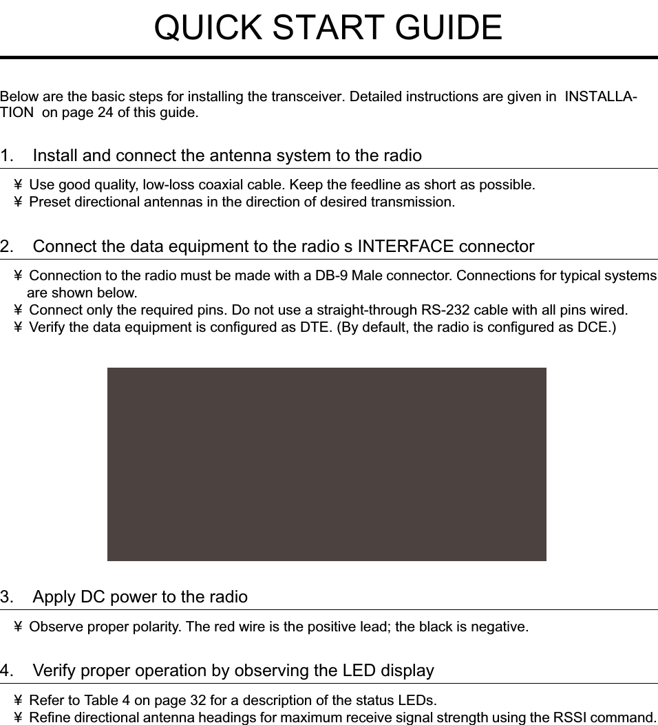
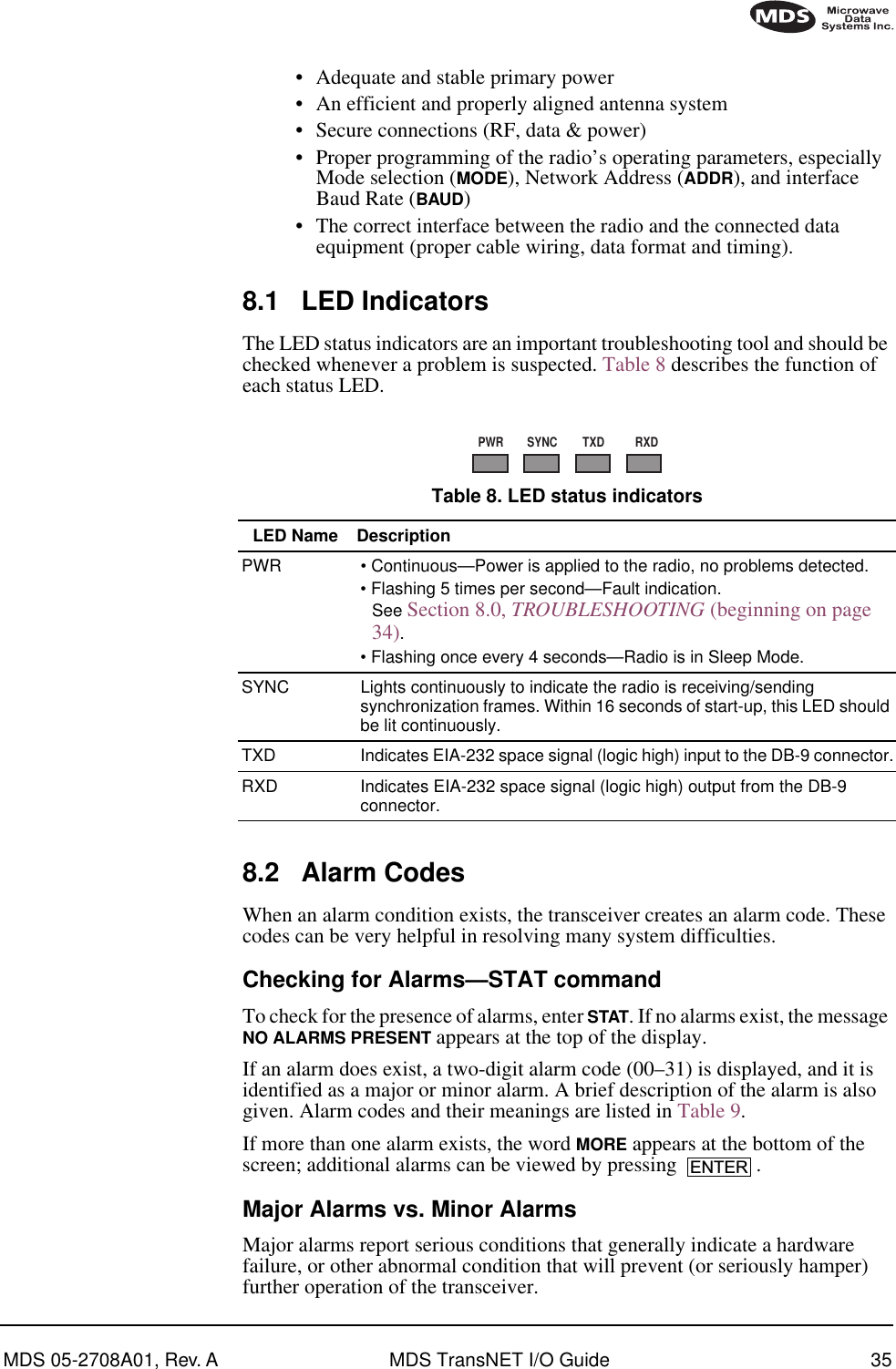
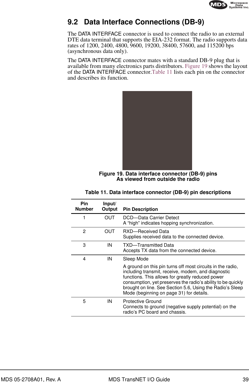
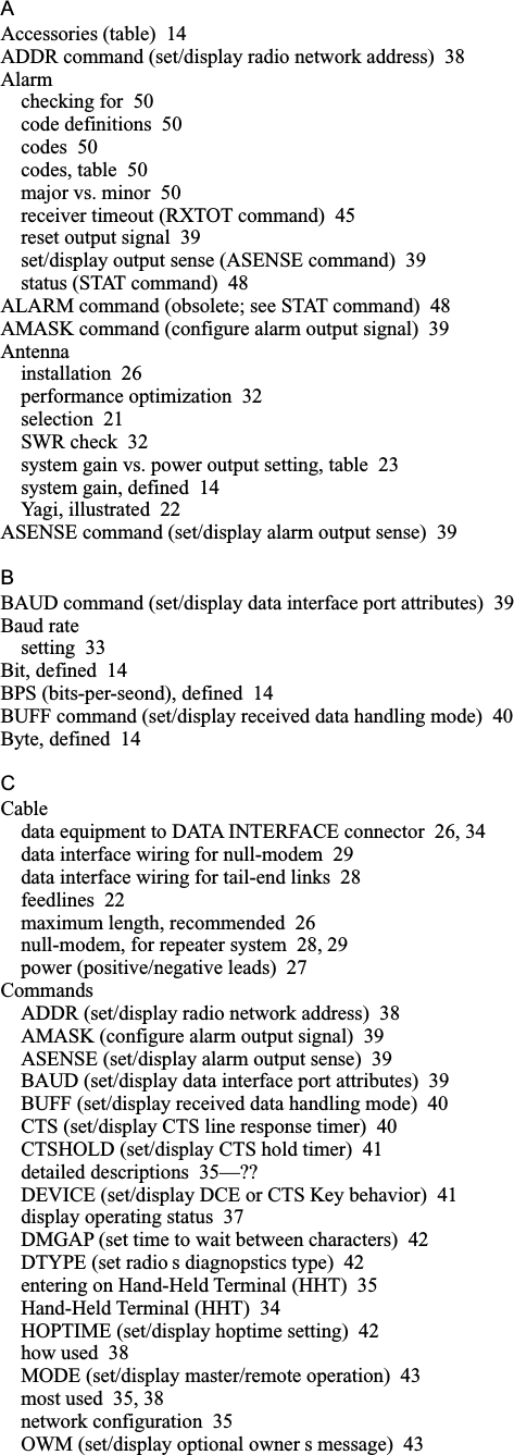
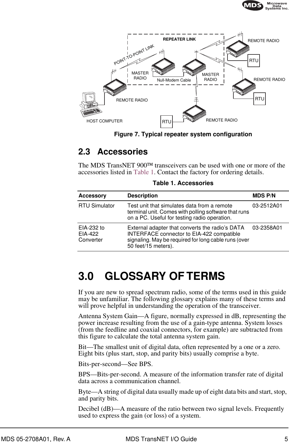
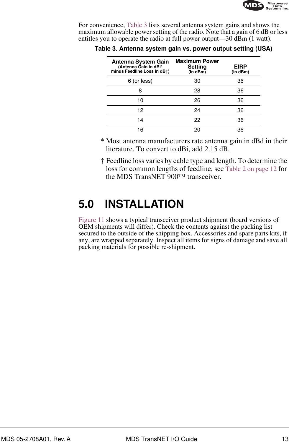
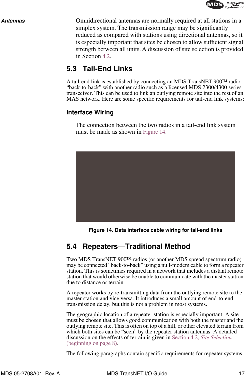
![MDS 05-2708A01 Rev. A MDS TransNET 900 I/O Guide iiSleep Mode Example ...................................................................31 6.0 OPERATION.............................................................................. 31 6.1 Initial Start-up ................................................................................. 316.2 Performance Optimization ..............................................................32Antenna Aiming ............................................................................ 32Antenna SWR Check....................................................................32Data Buffer Setting .......................................................................33Hoptime Setting ............................................................................33Baud Rate Setting ........................................................................33Radio Interference Checks ...........................................................33 7.0 TRANCEIVER PROGRAMMING............................................... 33 7.1 Programming Methods ...................................................................347.2 Keyboard Commands ....................................................................34Entering Commands.....................................................................357.3 Detailed Command Descriptions ....................................................38ADDR [1...65000] .........................................................................38AMASK [0000 0000—FFFF FFFF] ................................................39ASENSE [HI/LO]...........................................................................39BAUD [xxxxx abc].........................................................................39BUFF [ON, OFF]...........................................................................40CTS [0—255] .................................................................................40CTSHOLD [0-6000] ......................................................................41DEVICE [DCE, CTS KEY] ...........................................................41DMGAP [xx]..................................................................................42HOPTIME .....................................................................................42MODE [M, R, R-M] .......................................................................43OWM [xxxxx] ................................................................................43OWN [xxxxx].................................................................................43PWR [xx—30].................................................................................43RSSI .............................................................................................43RTU [ON/OFF/0-80]......................................................................44RX [xxxx] ......................................................................................44RXTOT [NONE, 0—1440] ..............................................................45SEND [n, -n, +n] ...........................................................................45SETUP..........................................................................................46SHOW [PORT, DC, PWR] ............................................................47SKIP [NONE, 1...8] .......................................................................47SSNR............................................................................................47SREV............................................................................................48STAT .............................................................................................48TTEMP .........................................................................................48TX [xxxx].......................................................................................48UNIT [10000—65000] ....................................................................49 8.0 TROUBLESHOOTING............................................................... 49 8.1 LED Indicators ................................................................................498.2 Alarm Codes ...................................................................................50](https://usermanual.wiki/GE-MDS/TRANSNET900/User-Guide-224698-Page-4.png)


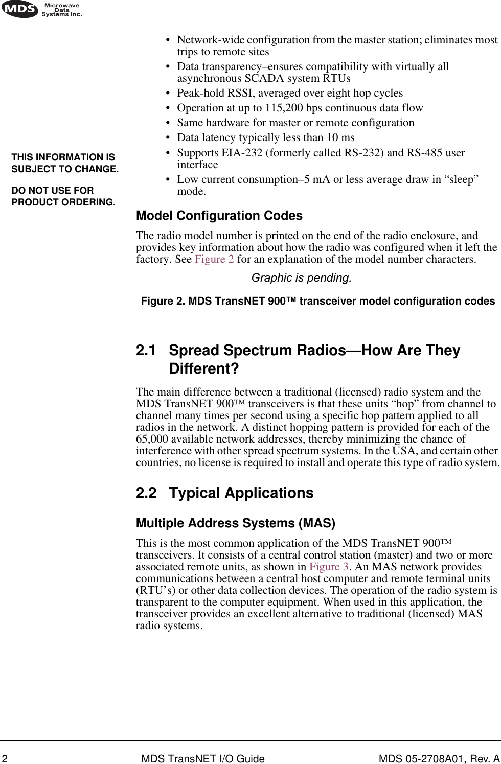
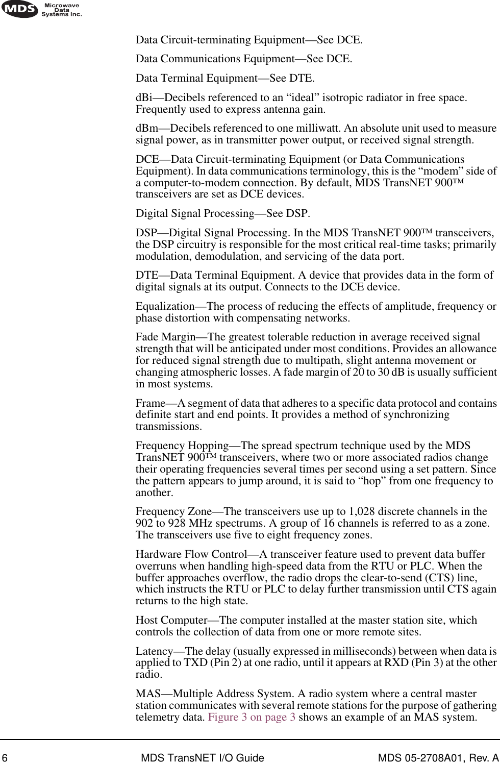
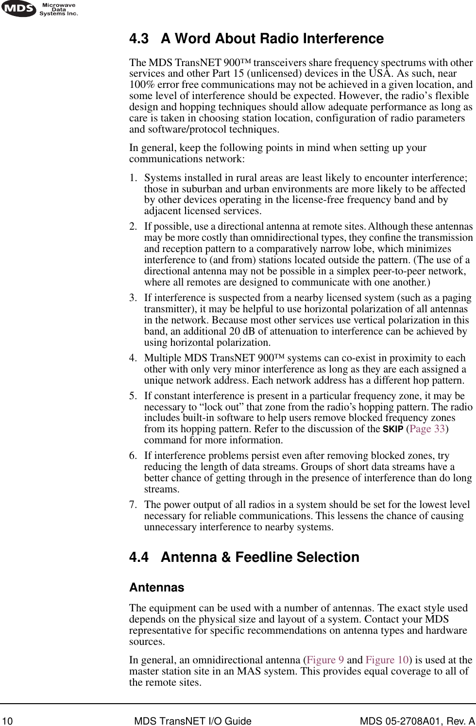
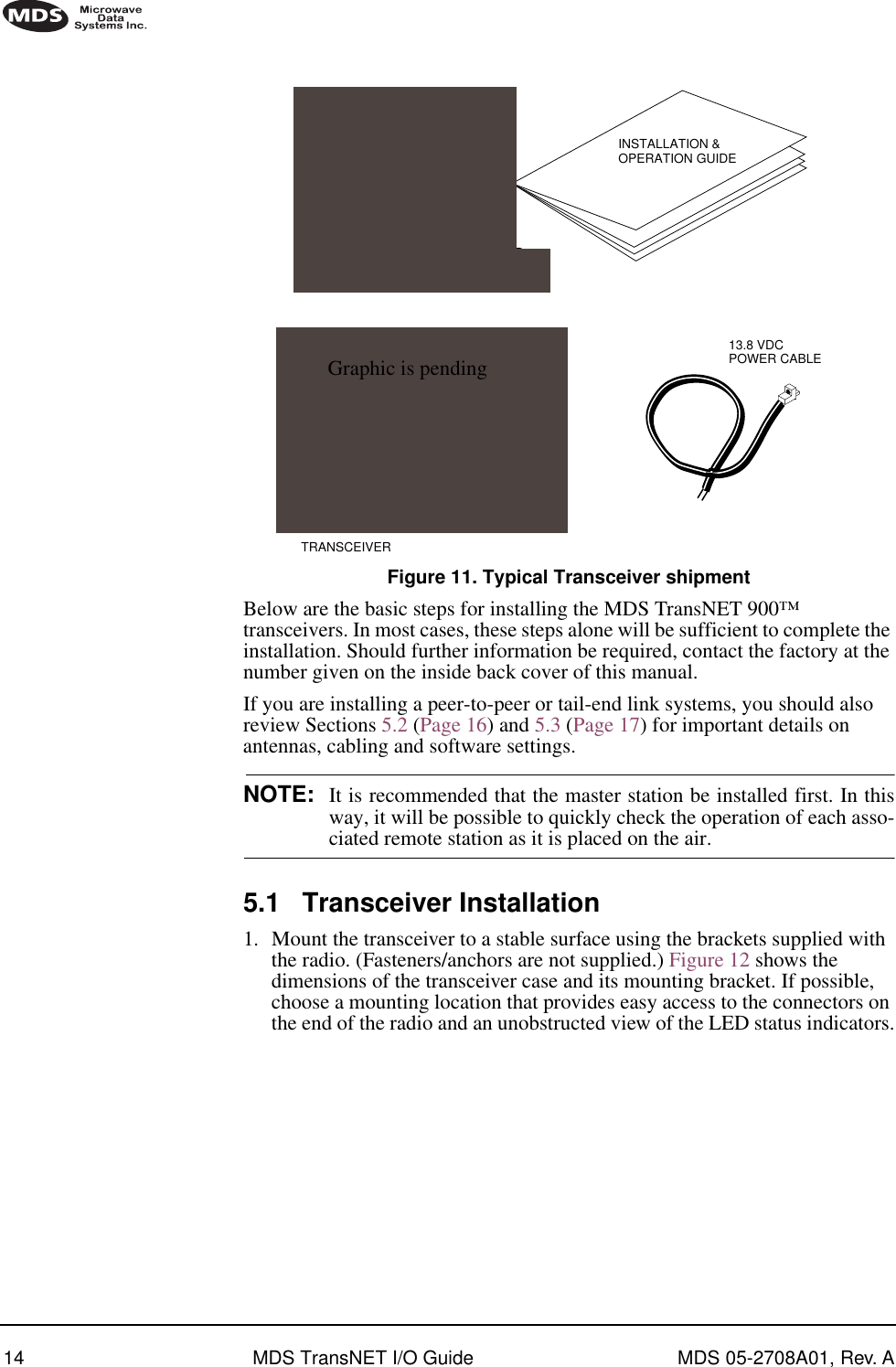
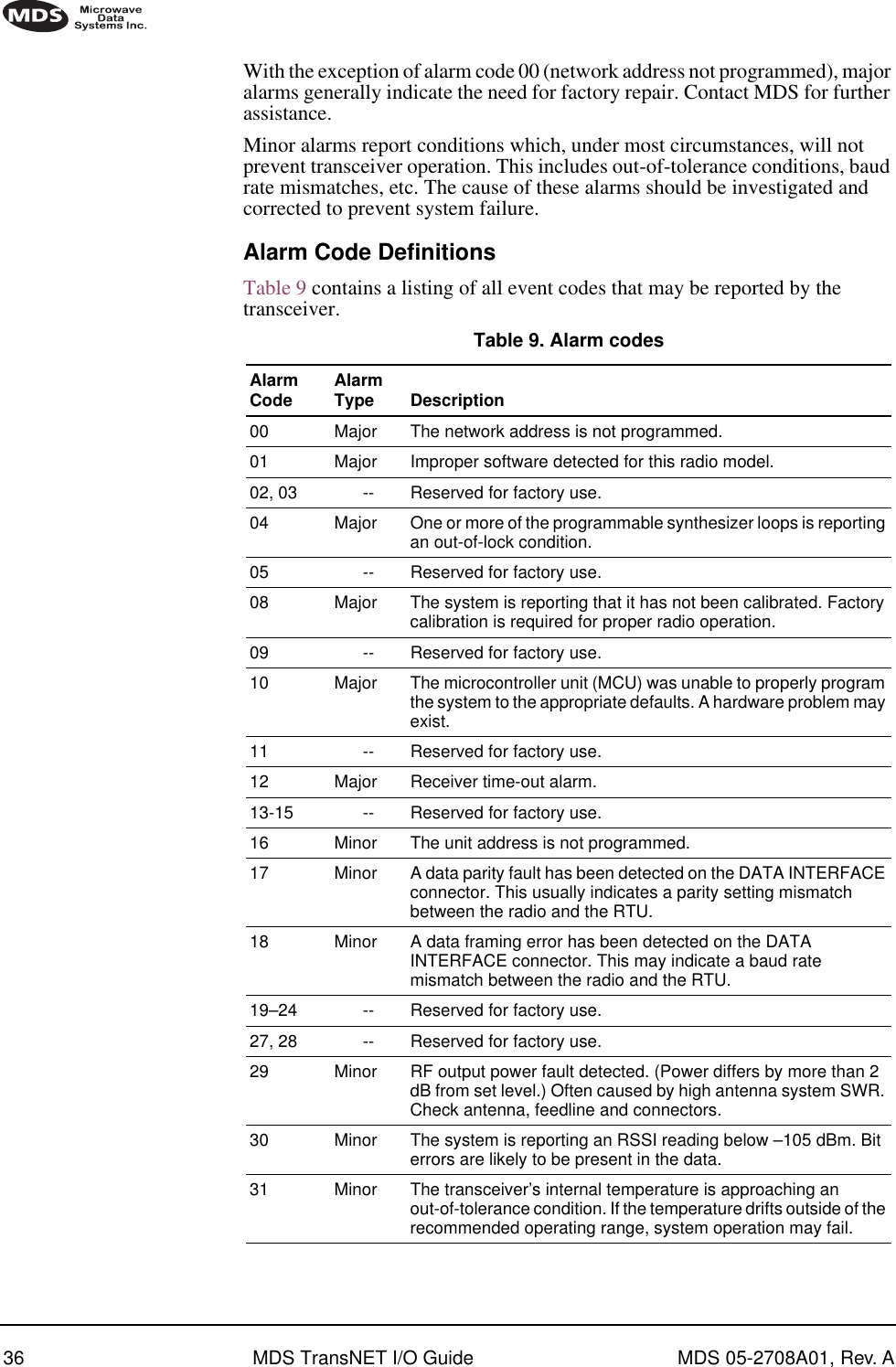
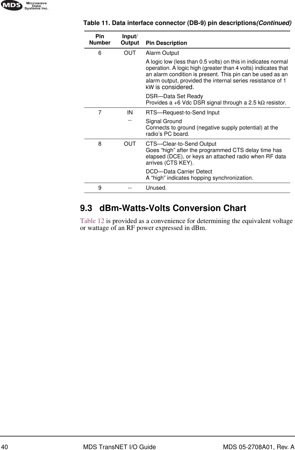
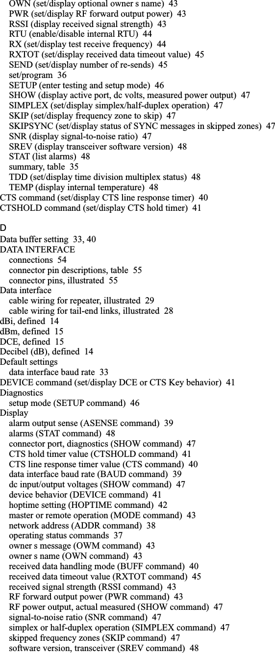
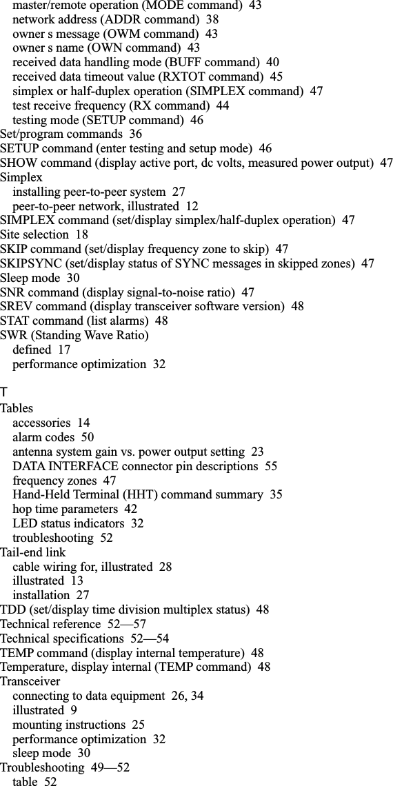
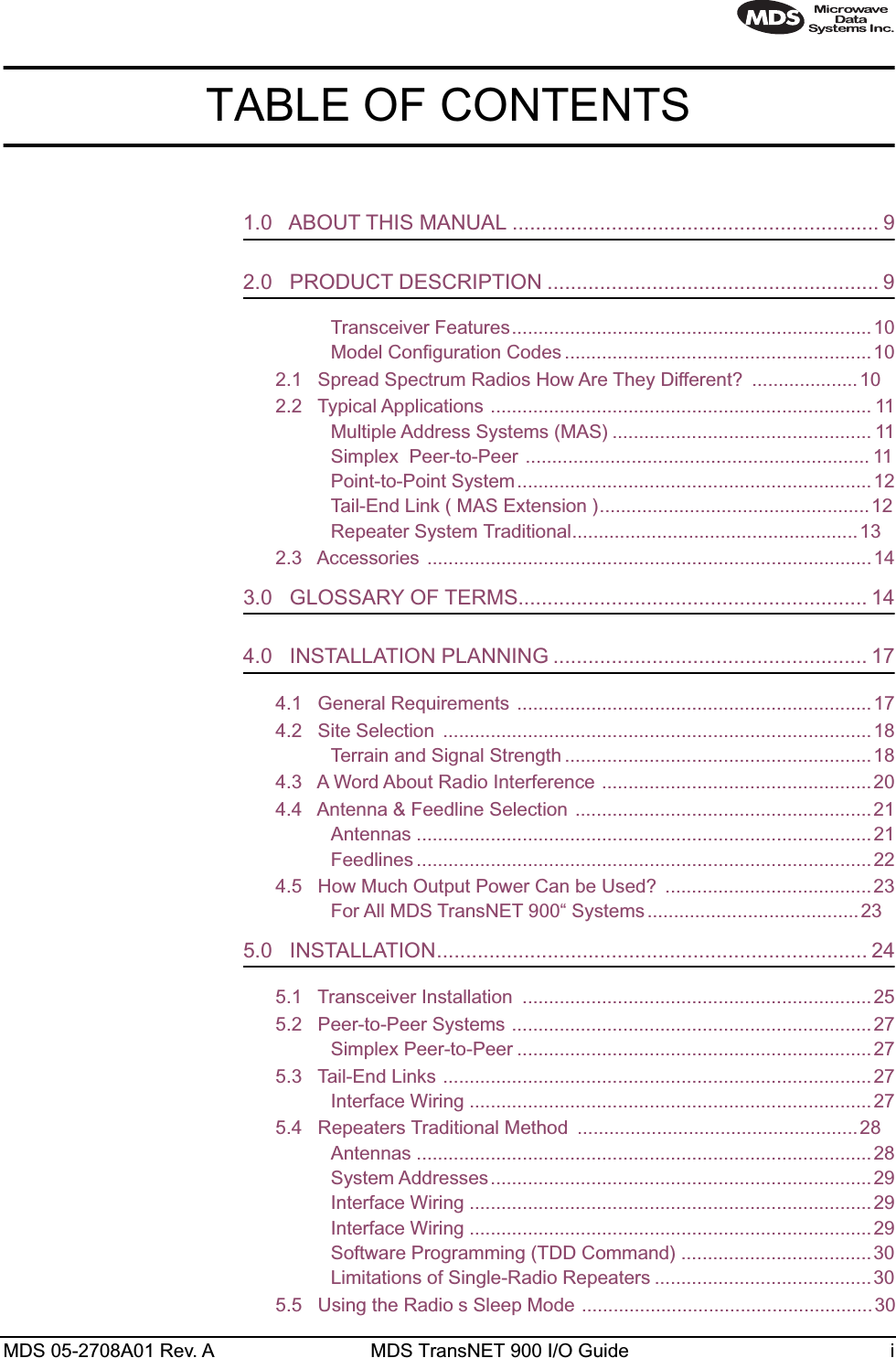
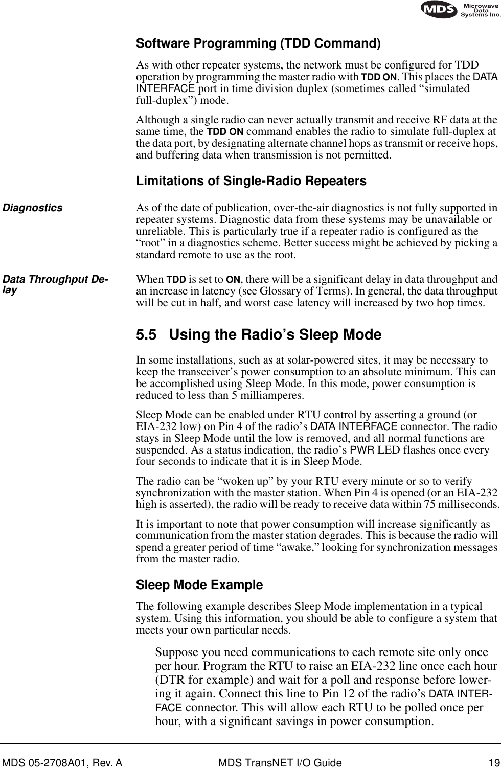
![18 MDS TransNET I/O Guide MDS 05-2708A01, Rev. AAntennasTwo antennas are required at repeater stations—one for each radio. Measures must be taken to minimize the chance of interference between these antennas. One effective technique for limiting interference is to employ vertical separation. In this arrangement, one antenna is mounted directly over the other, separated by at least 10 feet (3 Meters). This takes advantage of the minimal radiation exhibited by most antennas directly above and below their driven elements.Another interference reduction technique is to cross-polarize the repeater antennas. If one antenna is mounted in the vertical plane, and the other in the horizontal plane, an additional 20 dB of attenuation can be achieved. (Remember that the corresponding stations must use the same antenna orientation when cross-polarization is used.)System AddressesThe two radios that are wired together at the repeater site must have different system addresses. To set or view the system address, see “ADDR [1...65000]” on page 26.Interface WiringA null-modem cable (Figure 15) is required between the DATA INTERFACE connectors of the two radios forming a repeater station. This allows them to freely exchange data even though they are both configured as DCE devices.Invisible place holderFigure 15. Data interface cable wiring for null-modem cable(used for traditional repeater)Interface WiringA single-radio repeater is formed by connecting TXD (Pin 2) and RXD (Pin 3) on the DATA INTERFACE connector together as shown in Figure 16.Invisible place holderFigure 16. Data interface cable wiring for single-radio repeaterDB-25DATA INTERFACECONNECTOR23TXDRXDPins 2 & 3Connected Togetherfor Single-Radio Repeater](https://usermanual.wiki/GE-MDS/TRANSNET900/User-Guide-224698-Page-26.png)
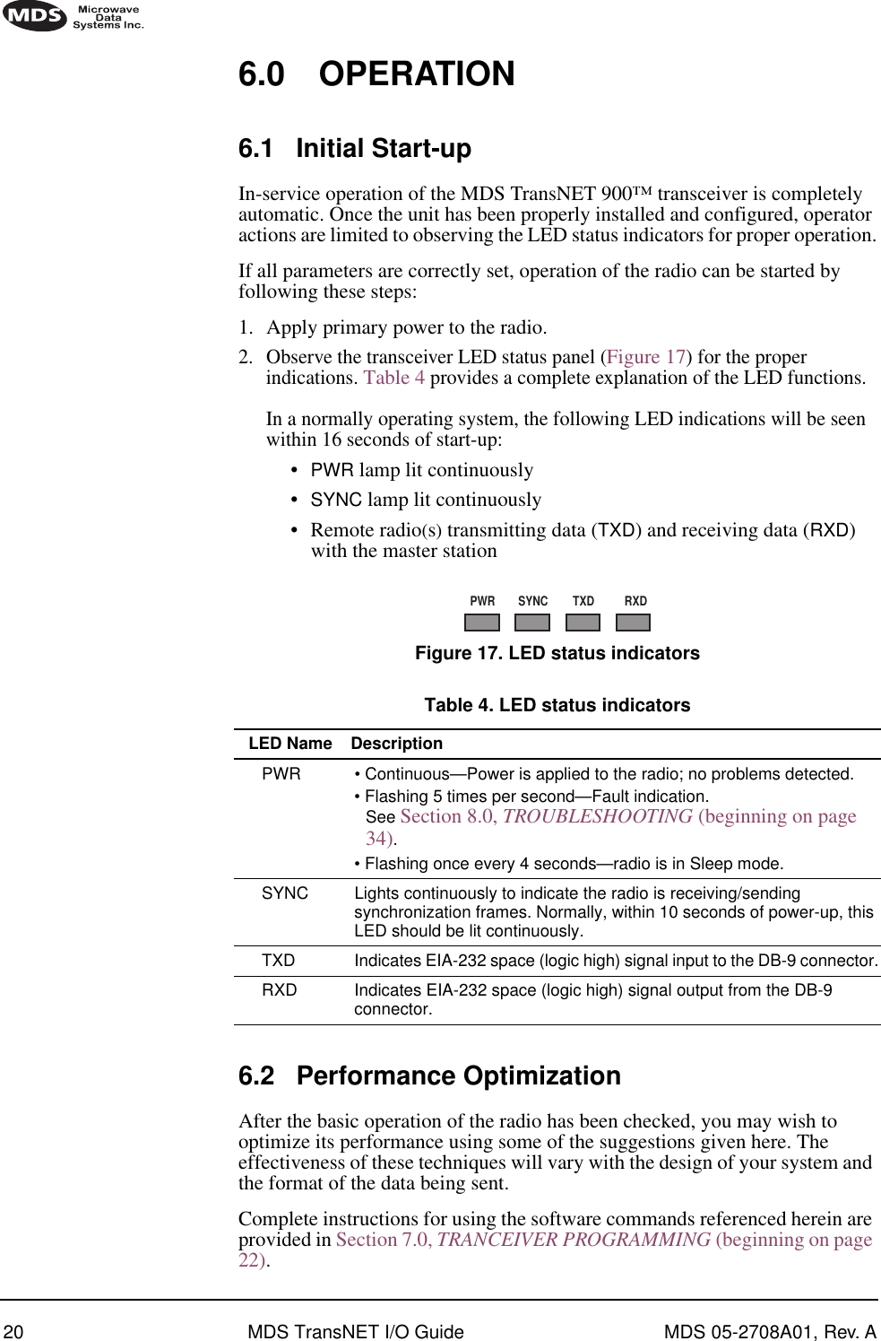
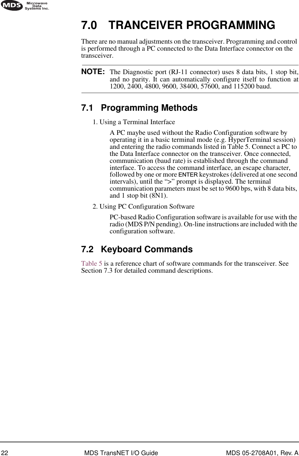
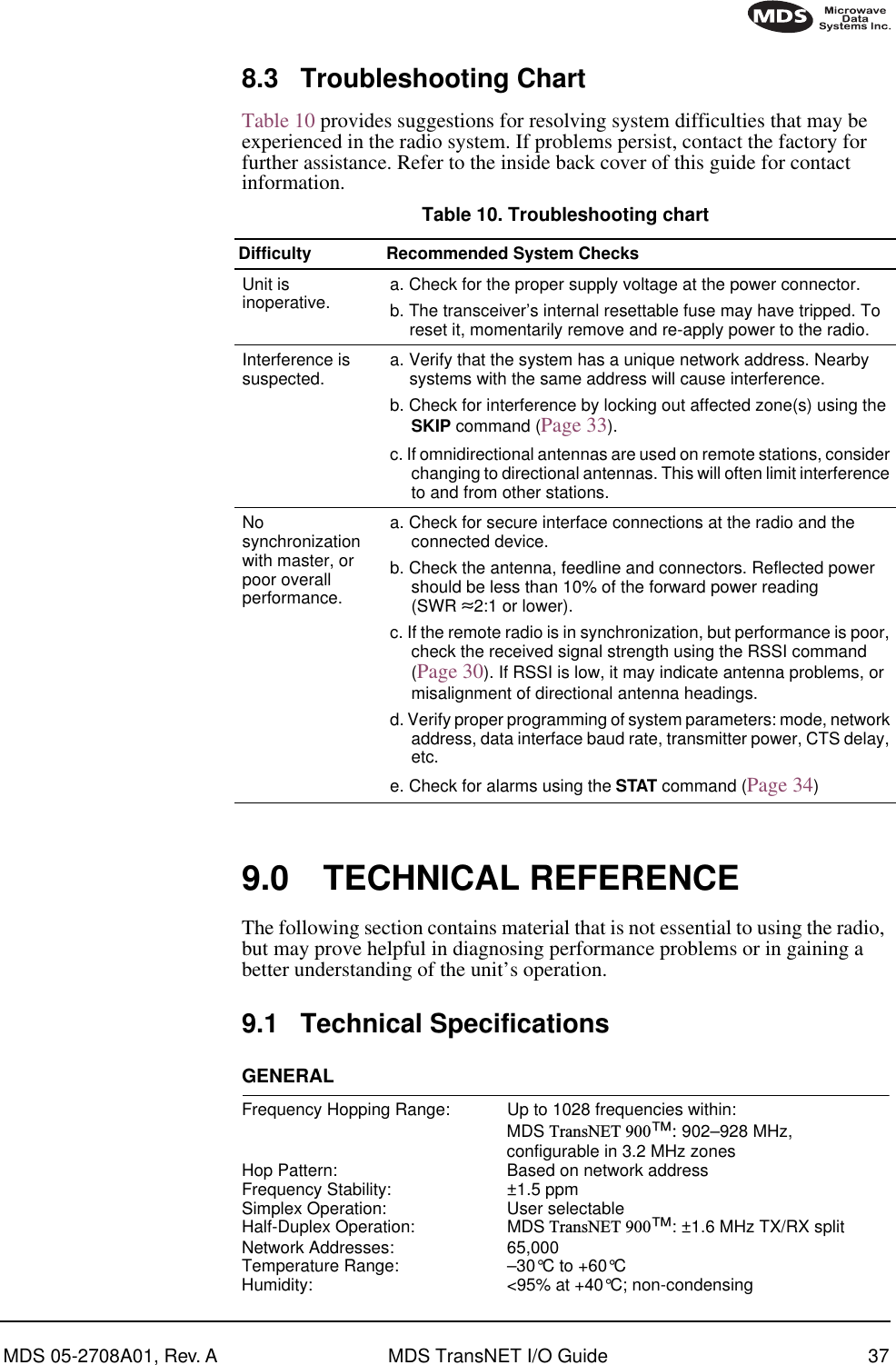
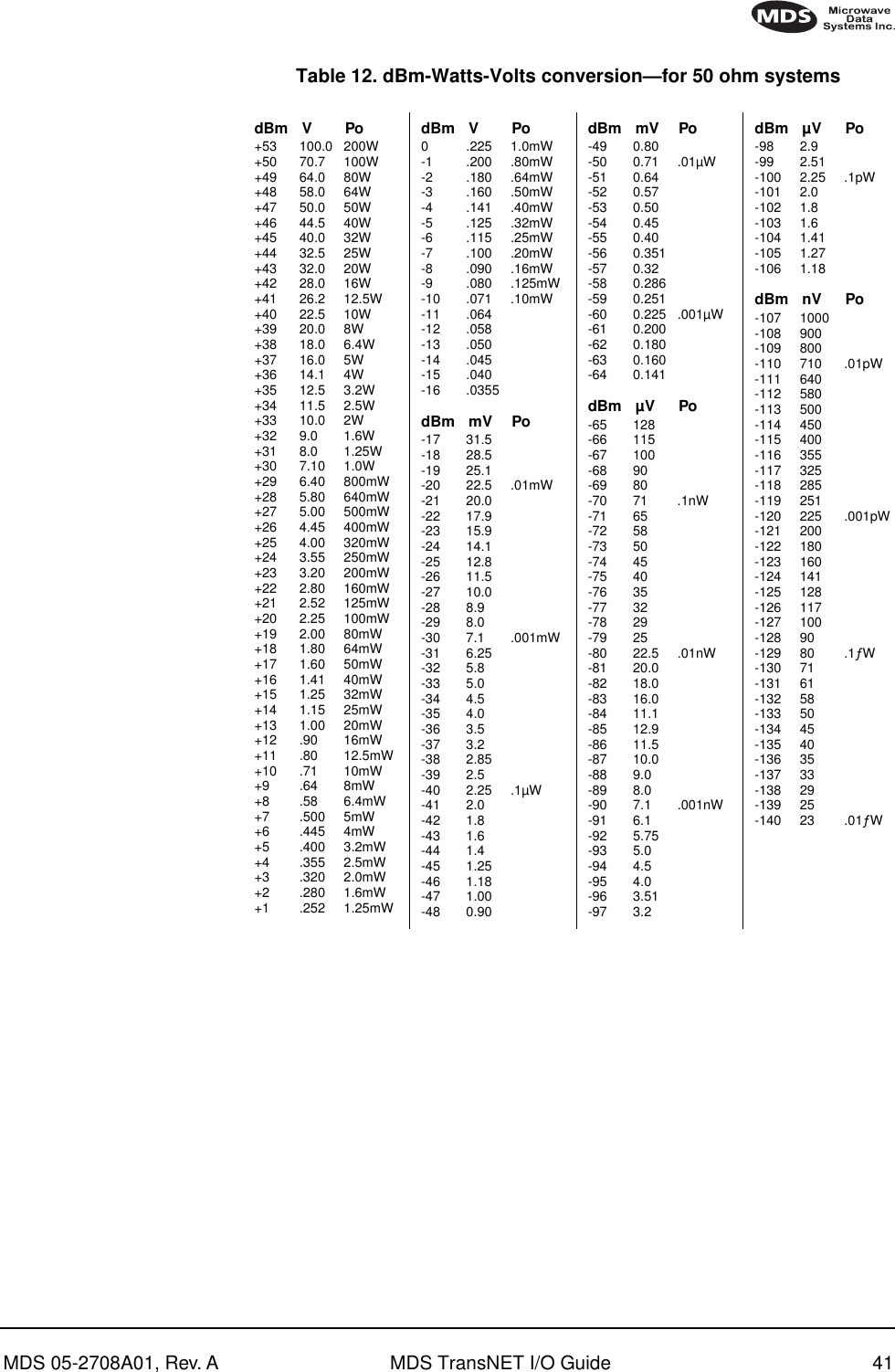
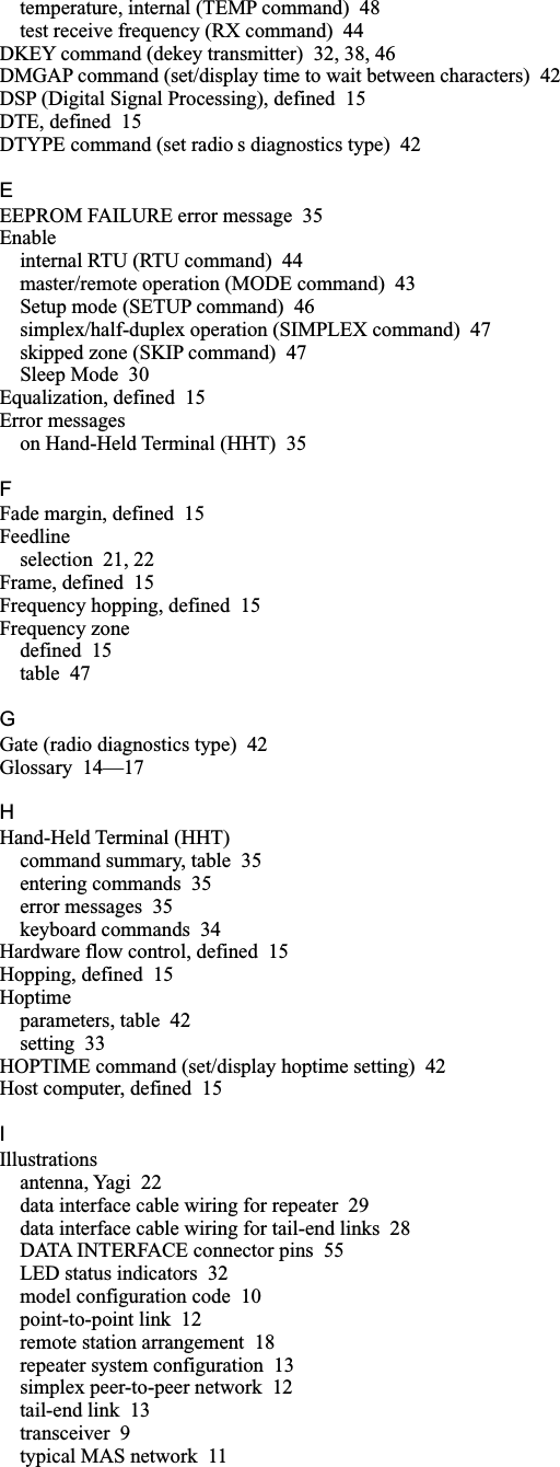
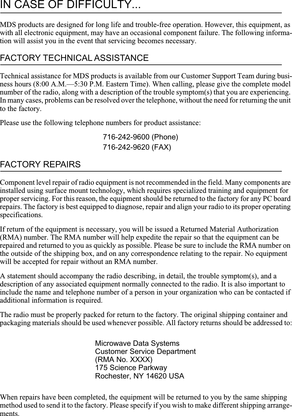
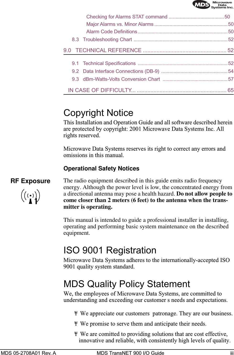
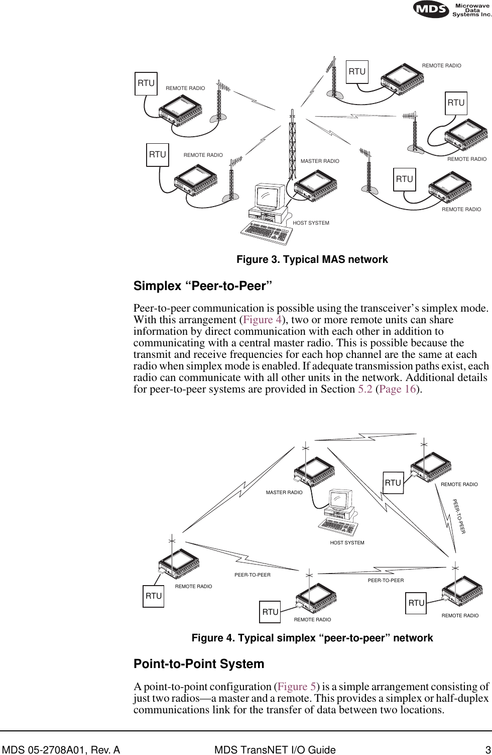
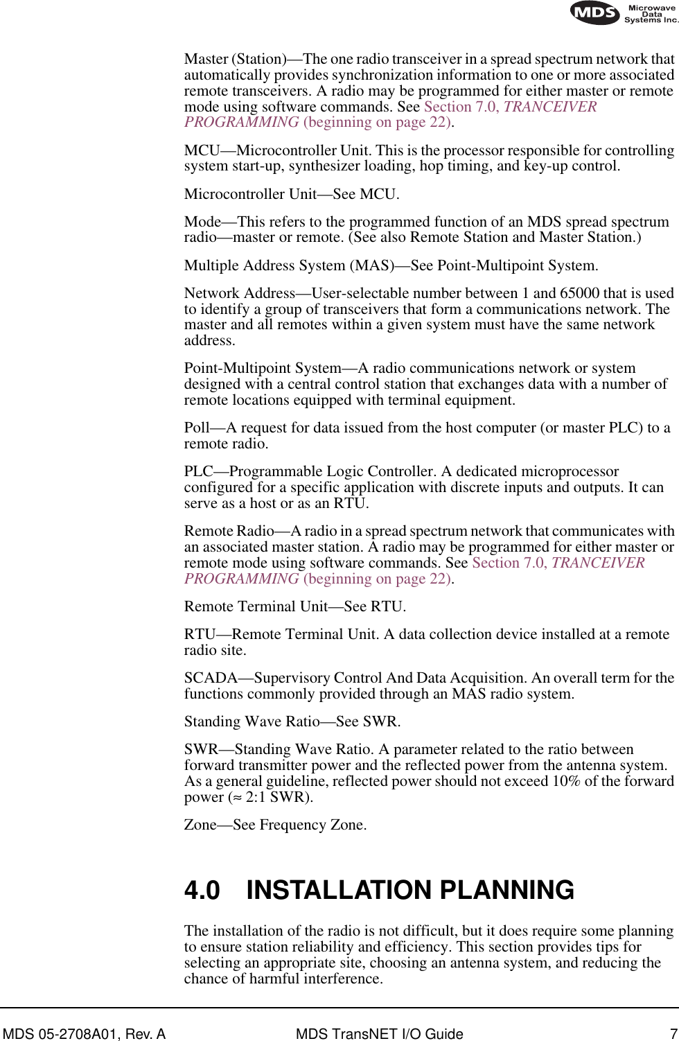
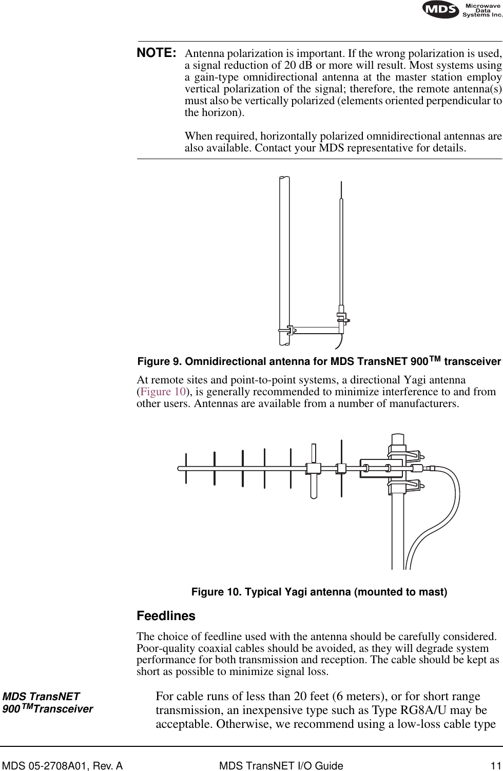
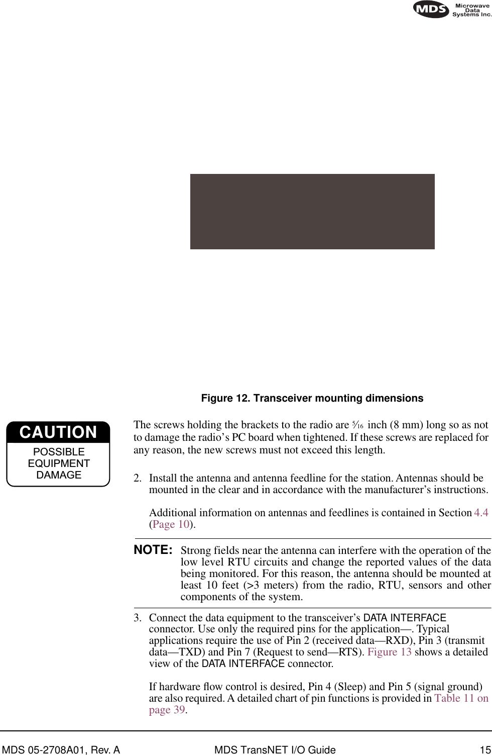
![MDS 05-2708A01, Rev. A MDS TransNET I/O Guide 23Entering CommandsThe proper procedure for entering commands is to type the command, followed by an keystroke. For programming commands, the command is followed by and the appropriate information or values, then .Table 5. Command summary COMMAND DESCRIPTION NETWORKCONFIGURATIONThese programming commandscan only be set at the master radio.BUFF [ON, OFF] Details Page 27ON = Seamless data, OFF = Fast byte through-put.HOPTIMEDetails Page 35Displays hop timeSEND [n, -n, +n] Details Page 31Sets/displays re-send count for data packets. Useful in areas with heavy radio interference.SKIP [NONE, 1...8] Details Page 33Select combination of frequency operating zones to avoid.ENTERSPACEENTER](https://usermanual.wiki/GE-MDS/TRANSNET900/User-Guide-224698-Page-31.png)
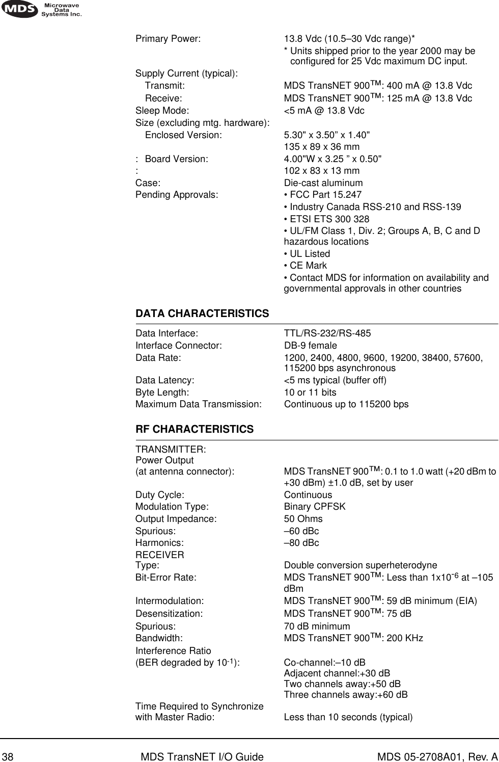
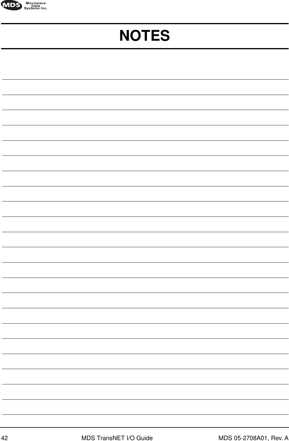
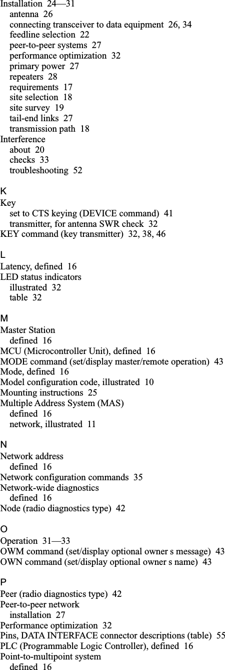
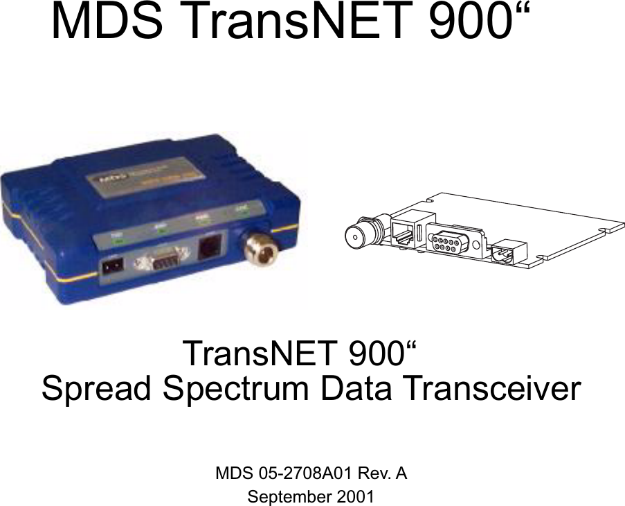
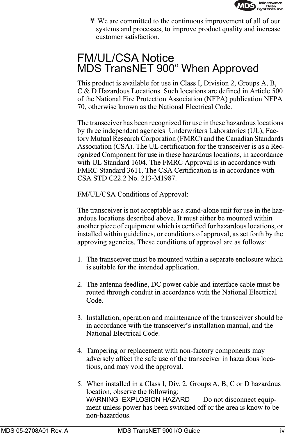
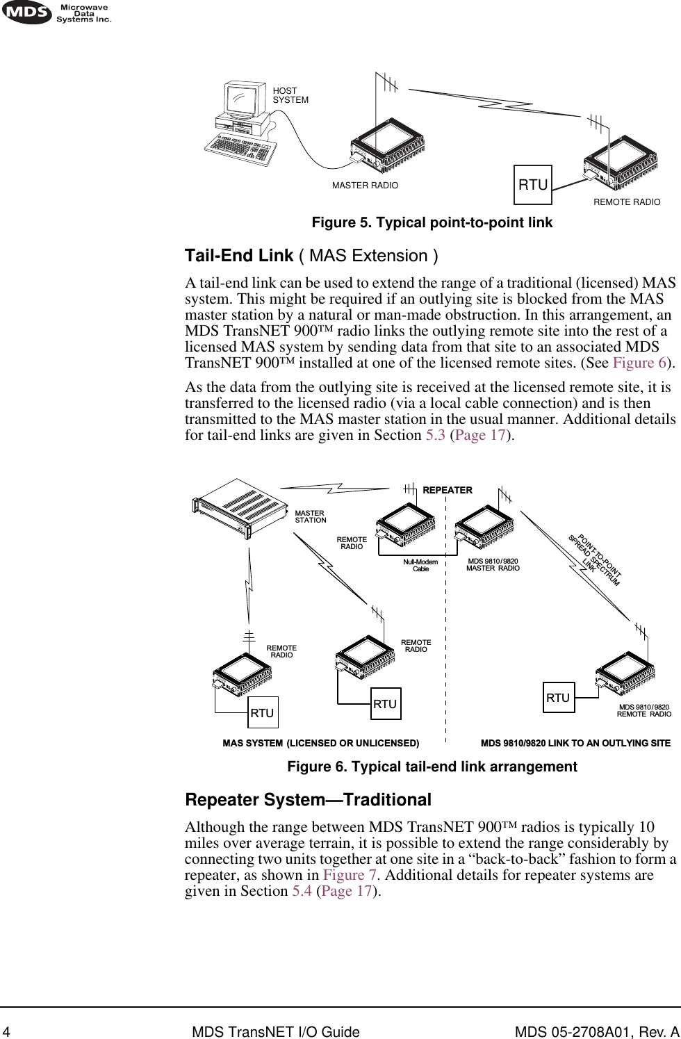
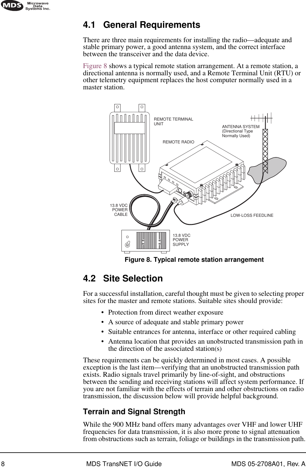
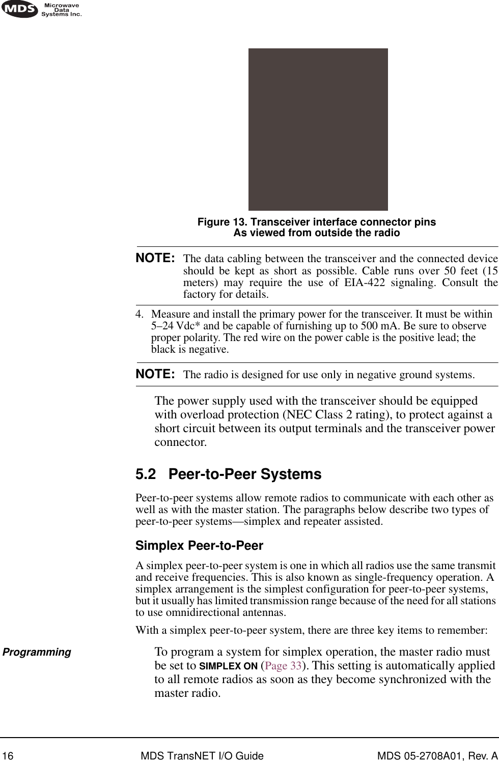
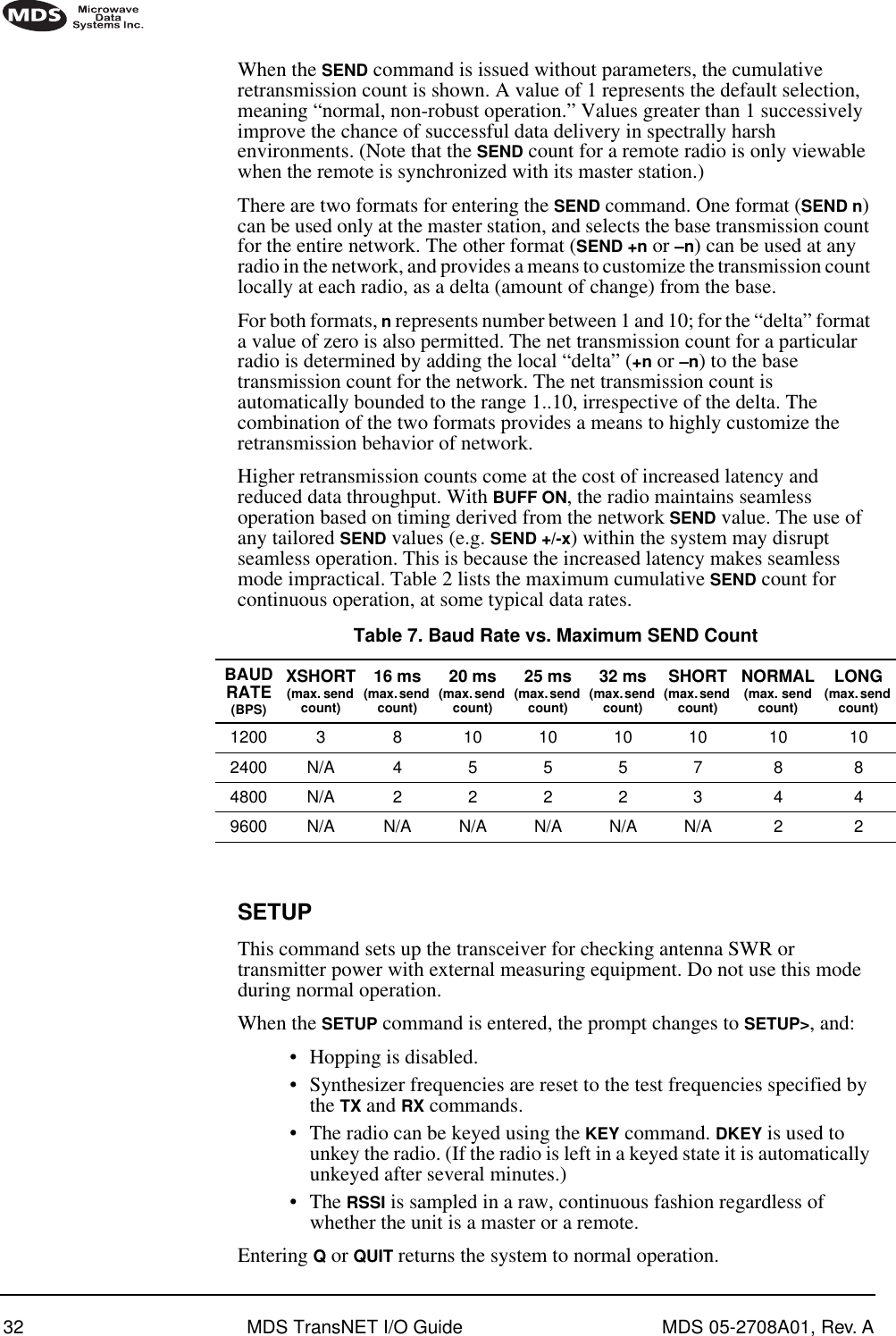
![24 MDS TransNET I/O Guide MDS 05-2708A01, Rev. ASET/PROGRAM COMMANDSADDR [1...65000] Details Page 26 Program network addressAMASK [0000 0000–FFFF FFFF] Details Page 27Sets alarm response. Default is FFFF FFFF. ASENSE [HI/LO] Details Page 27Changes the sense of the alarm output. Default sense is HI. BAUD [xxxxx abc] Details Page 27Set data communication parametersCTS [0–255] Details Page 28Program CTS delay in milliseconds.(A value of 0 returns CTS immediately)CTSHOLD [0-6000] Details Page 28Set/display “hold time” that CTS remains present following last character transmission from DD-25 port.DEVICE [DCE, CTS KEY] Details Page 28 Set device behavior; DCE (normal) or CTS Key (Repeater)MODE [M, R, R-M] Details Page 30Program operating mode, where M = Master,R = Remote, R-M = Remote-Master (Remote radio programmed to operate on Master fre-quencies)OWM [xxxxx] Details Page 30Program owner’s message(30 characters maximum)OWN [xxxxx] Details Page 30Program owner’s name(30 characters maximum)PWR [xx–30] Details Page 30Program forward power output in dBm.RTU [ON/OFF/0-80] Details Page 31Re-enables or disables the radio’s internal RTU simulator and sets the RTU address.RXTOT [NONE, 0–1440] Details Page 31Specifies max. duration (in minutes) to wait before issuing a time-out alarm. Default is OFF. SEND [n, -n, +n] Details Page 31Sets/displays re-send count for data packets. Useful in areas with heavy radio interference.UNIT [10000–65000] Details Page 34Program unit address. Used to set a unique address for network-wide diagnostics.Table 5. Command summary (Continued)COMMAND DESCRIPTION](https://usermanual.wiki/GE-MDS/TRANSNET900/User-Guide-224698-Page-32.png)
![MDS 05-2708A01, Rev. A MDS TransNET I/O Guide 25DISPLAY OPERATING STATUSADDR [1...65000] Details Page 26Network address (1-65000)AMASK [0000 0000–FFFF FFFF] Details Page 27Sets alarm mask (response). Default is FFFF FFFF.ASENSE [HI/LO] Details Page 27Changes the sense of the alarm output. Default sense is HI.BAUD [xxxxx abc] Details Page 27Display data communication parameters. Example: BAUD 9600 8N1BUFF [ON, OFF] Details Page 27Data buffering mode: ON = seamless dataOFF = fast byte throughputCTS [0–255] Details Page 28CTS delay in ms (0-255 ms)DEVICE [DCE, CTS KEY] Details Page 28Device behavior (DCE, or CTS KEY)HOP-TIME Details Page 29Show hop time in milliseconds (ms).HREV Hardware revision levelMODE [M, R, R-M] Details Page 30Show operating mode: M = Master, R = Remote, R-M = Remote-Master (remote oper. on master freqs.)OWM Owner’s message or site nameOWN Owner’s name or system namePWR [xx–30] Details Page 30Forward power output setting in dBmRSSI Details Page 30Received signal strength in dBm (continuously updated). Not available at master radio unless SETUP is enabled.RXTOT [NONE, 0–1440] Details Page 31Specifies amount of time (in seconds) to wait before issuing a time-out alarm. Default is NONE. SEND [n, -n, +n] Details Page 31Sets/displays re-send count for data packets. Useful in areas with heavy radio interference.SER Serial number of radioSHOW [PORT, DC, PWR] Details Page 33Show active port, DC voltage or measured RF power (dBm)SKIP [NONE, 1...8] Details Page 33Simplex/half-duplex selectionON = Simplex, OFF = half-duplexSKIP [NONE, 1...8] Details Page 33Skip a frequency operating zoneTable 5. Command summary (Continued)COMMAND DESCRIPTION](https://usermanual.wiki/GE-MDS/TRANSNET900/User-Guide-224698-Page-33.png)
![26 MDS TransNET I/O Guide MDS 05-2708A01, Rev. A7.3 Detailed Command DescriptionsThe essential commands for most applications are Network Address (ADDR), Mode, (MODE) and Baud Rate (BAUD). However, proper use of the additional commands allows you to tailor the transceiver for a specific use, or to conduct basic diagnostics on the radio. This section gives more detailed information for many of the user commands listed in Table 5.Most of the commands below can be used in two ways. First, you can type only the command name (for example, ADDR) to view the currently programmed data. Second, you can set or change the existing data by typing the command, followed by a space, and then the desired entry (for example, ADDR 1234). In the list below, allowable programming variables, if any, are shown in brackets [ ] following the command name.ADDR [1...65000]This command sets or displays the radio’s network address. The network address can range from 1 to 65000.Network address must be programmed at the time of installation and must be common across each radio in a given network. Radios are typically shipped with the network address unprogrammed. This causes the address to display as NONE. This leaves the system in an invalid state and prevents operation.DISPLAY OPERATING STATUS(CONTINUED)SSNR Details Page 33Signal-to-noise ratio. Expressed in dB.SREV Details Page 34Display transceiver firmware revision levelSTAT Details Page 34Show current alarm statusTTEMP Details Page 34Transceiver’s internal temperature (°C)UNIT [10000–65000] Details Page 34Show programmed unit address for net-work-wide diagnosticsDIAGNOSTIC/TESTKEY Enables the transmitter. (Radio must be in Setup mode.)DKEY Disables the transmitter. (Radio must be in Setup mode.)TX [xxxx] Details Page 34Set/display transmit test frequency. (Radio must be in Setup mode.)RX [xxxx] Details Page 31Set/display receive test frequency. (Radio must be in Setup mode.)SETUP Details Page 32Enables Setup mode. Times out after 15 min-utes. Press “Q” to quit.Table 5. Command summary (Continued)COMMAND DESCRIPTION](https://usermanual.wiki/GE-MDS/TRANSNET900/User-Guide-224698-Page-34.png)
![MDS 05-2708A01, Rev. A MDS TransNET I/O Guide 27NOTE: It is recommended that the last four digits of the master radio’s serialnumber be used for the network address (or chassis serial number ifthe radio is installed in a P-20 redundant chassis).ALARMTable and information pending.AMASK [0000 0000–FFFF FFFF]This command sets the alarm bits that cause the alarm output signal to be triggered. The PWR LED will still flash for all alarms, but the alarm output signal will only be activated for those alarms that have the corresponding mask bit set. The hex value for the mask aligns directly with the hex value for the ALARM command. The default is FFFF FFFF. Through proper use of the AMASK command, it is possible to tailor the alarm response of the radio. Contact the factory for more information on configuring the alarm mask.ASENSE [HI/LO]This command is used to set or display the sense of the alarm output at Pin 25 of the DATA INTERFACE connector. The default for transceivers is active HI.BAUD [xxxxx abc]This command sets or displays the communication attributes for the DATA INTERFACE port. The command has no effect on the RJ-11 DIAG(NOSTICS) port.The first parameter (xxxxx) is baud rate. Baud rate is specified in bits-per-second and must be one of the following speeds: 1200, 2400, 4800, 9600, 19200, or 38400. In the worst case, the radio will always accept a minimum of 500 data bytes in a single continuous data transmission. At baud rates of 4800 bps or less, the radio can support unlimited continuous data transmission at any hop rate. If hop time is set to NORMAL or LONG, baud rates of up to 19200 bps with continuous unlimited data transmission are possible. (See HOPTIME command.)The second parameter of the BAUD command (abc) is a 3-character block indicating how the data is encoded. The following is a breakdown of each character’s meaning:a = Data bits (7 or 8)b = Parity (N for None, O for Odd, E for Even)c = Stop bits (1 or 2)The factory default setting is 4800 baud, 8 data bits, no parity, 1 stop bit (Example: 4800 8N1).NOTE: 7N1, 8O2, and 8E2 are invalid communication settings and are notsupported by the transceiver.BUFF [ON, OFF]This command sets or displays the received data handling mode of the radio. The command parameter is either ON or OFF. (The default is ON.) The setting of this parameter affects the timing of received data sent out the DATA INTERFACE connector. Data transmitted over the air by the radio is unaffected by the BUFF setting.](https://usermanual.wiki/GE-MDS/TRANSNET900/User-Guide-224698-Page-35.png)
![28 MDS TransNET I/O Guide MDS 05-2708A01, Rev. AIf data buffering is set to OFF, the radio will operate with the lowest possible average latency. Data bytes are sent out the DATA INTERFACE port as soon as an incoming RF data frame is disassembled. Average and typical latency will both be below 10 ms, but idle character gaps may be introduced into the outgoing data flow.If data buffering is ON, the radio will operate in a seamless mode. That is, data bytes will be sent over the air as quickly as possible, but the receiver will buffer the data until enough bytes have arrived to cover worst case gaps in transmission. The delay introduced by data buffering may range from 25 to 50 ms, but the radio will not create any gaps in the output data stream. This mode of operation is required for protocols such as MODBUS™ that do not allow gaps in their data transmission.that seamless mode (BUFF ON) is intended only for applications where the transmitter’s baud rate is greater than or equal to the receiver’s baud rate. Enforcement of this rule is left up to the user.Changes to the BUFF setting may only be made at the master radio. This is because the master radio broadcasts the buffer setting for the entire network. At remote radios, the buffer setting may be read when the radio is in synchronization with the master, but it may not be changed.CLOSTable and information pending.CTS [0–255]The CTS (clear-to-send) command sets or displays the timer value associated with the CTS line response. The command parameter ranges from 0 to 255 milliseconds.For DCE operation, the timer specifies how long to wait after the RTS line goes high before asserting the CTS line. A timer value of zero means that the CTS line will always be asserted (unless the radio is attempting to throttle back data as part of normal flow control operation).For CTS Key operation (see the DEVICE command), the timer specifies how long to wait after asserting the CTS line before sending data out the DATA INTERFACE port. A timer value of zero means that data will be sent out the data port without imposing a key-up delay. (Other delays may be in effect from other radio operating parameters.)CTSHOLD [0-6000]Used in DEVICE CTS KEY mode, this command sets the amount of time in milliseconds that CTS remains present following transmission of the last character out the RXD pin of the DATA INTERFACE port. This “hold time” can be used to prevent squelch tail data corruption when interworking with other radios.The CTSHOLD setting can range from 0 to 6000 (i.e., 6 seconds). The default value is 0, which means that CTS will drop immediately after the last character is transmitted. If the command is entered when the radio is in DEVICE DCE mode, the response CTSHOLD N/A will be displayed.DEVICE [DCE, CTS KEY]The DEVICE command sets or displays the device behavior of the radio. The command parameter is either DCE or CTS KEY.](https://usermanual.wiki/GE-MDS/TRANSNET900/User-Guide-224698-Page-36.png)
![MDS 05-2708A01, Rev. A MDS TransNET I/O Guide 29The default selection is DCE. In this mode, CTS will go high following RTS, subject to the CTS programmable delay time. Keying is stimulated by the input of characters at the data port. Hardware flow control is implemented by dropping the CTS line if data arrives faster than it can be transmitted.If CTS KEY is selected, the radio is assumed to be controlling another radio, such as in a repeater system. The RTS line is ignored and the CTS line is used as a keyline control for the other radio. CTS is asserted immediately after the receipt of RF data, but data will not be sent out the DATA INTERFACE port until after the CTS programmable delay time has expired. (This gives the other radio time to key.)Following transmission of the last byte of data, CTS will remain asserted for the duration specified by the CTSHOLD command. CTSHOLD should be set sufficiently high.DMGAP [xx]The DMGAP command sets the amount of time in milliseconds to wait after the receipt of a character before interpreting the next received character as the start of a new message. When data port baud rates are slow, the gap between characters within a poll may be so long that the radio interprets the next character as the start of a new poll. When diagnostics is being performed using passive messaging, this command may be used to change this behavior.HOPTIMEThe HOPTIME command sets or displays the hop time setting. The command is one of eight keywords whose parameters and related efficiencies are shown in Table 6.Although the default setting is 7, transmission efficiency can usually be improved by using a setting of 28 when data rate exceeds 115200 bps. This is because there will be less frequent channel hops when using this setting, contributing to a smoother flow of transmitted data.Other hop times can be used to customize performance based on SEND count settings and payload data poll length.The only time shorter settings (SHORT through XSHORT) should be considered is when the message size is very small and strong interference of a persistent nature is occurring on many frequencies. In these cases, a shorter hop time may improve the chances of a message getting through—but at the cost of reduced channel efficiency.Table 6. Hoptime parametersHop Time KeywordTime per HopMax. Bytesper Hop ChannelEfficiencyXSHORT 10 ms 9 32.1%16 16 ms 21 46.7%20 20 ms 30 53.6%25 25 ms 39 55.7%32 32 ms 57 63.3%SHORT 40 ms 72 64.3%NORMAL 80 ms 162 72.0%LONG 160 ms 336 74.5%](https://usermanual.wiki/GE-MDS/TRANSNET900/User-Guide-224698-Page-37.png)
![30 MDS TransNET I/O Guide MDS 05-2708A01, Rev. AChanges to the HOPTIME setting may only be made at the master radio. (This is because the master radio establishes the hop time setting for the entire network.) At remote radios, the hop time setting may be read when the radio is in synchronization with the master, but it may not be changed.MODE [M, R, R-M]The MODE command sets or displays the operating mode of the radio. A master radio is designated by an M; a remote is designated by an R.R-M indicates that the transceiver has been programmed to the special remote-master mode (remote radio operating on master frequencies) This is used in repeater-assisted peer-to-peer systems; see Section 2.2, Typical Applications (beginning on page 2) for details. The R-M mode denotes a remote radio operating on master frequencies. In all other respects, a remote-master behaves the same as a normal remote.All units default to remotes; other modes must be specifically programmed with the MODE command.OPTION!Table and information pending.OWM [xxxxx]The OWM command sets or displays an optional owner’s message, such as the system name. The entry can contain up to 30 characters.OWN [xxxxx]The OWN command sets or displays an optional owner’s name, such as the site name. The entry can contain up to 30 characters.PWR [xx–30]This command displays or sets the desired RF forward output power setting of the radio. The PWR command parameter is specified in dBm and can range from 20 dBm (MDS TransNET 900™ transceiver) through 30 in 1 dBm steps. The default setting is 30 dBm (1 watt). To read the actual (measured) power output of the radio, use the SHOW PWR command.In the USA, maximum allowable power is governed by FCC limits on Effective Isotropic Radiated Power output (EIRP). The EIRP limit of +36 dBm means that any user with a net antenna gain greater than 6 dBi must decrease the PWR setting accordingly. Section 4.5, How Much Output Power Can be Used? (beginning on page 12) contains a detailed discussion of this topic.RSSIThis command displays the radio’s Received Signal Strength Indication in dBm (decibels relative to 1 mW). The output can range from –50 dBm to –110 dBm. Command availability and results depend on the mode of operation (master or remote). The closer to 0 dBm, the stronger the signal, thus a reading of –70 dBm is stronger than –80 dBm.](https://usermanual.wiki/GE-MDS/TRANSNET900/User-Guide-224698-Page-38.png)
![MDS 05-2708A01, Rev. A MDS TransNET I/O Guide 31For a remote radio, under normal operation, RSSI is based on the average signal strength of the SYNC message received in each of the eight frequency zones. (RSSI is sampled each time a SYNC message is received—every 1.6 seconds.) When using the RSSI reading to align a directional antenna, it is important to make changes slowly so that the RSSI reading will provide meaningful results. It will take several seconds to indicate a change in signal level. The radio stays in RSSI mode until is pressed.For a master radio, under normal operation, entering the RSSI command causes the response NOT AVAILABLE to be returned. This is because a master is normally receiving signals from several remote stations and an RSSI reading would be continually changing. The only exception is when the SETUP command has been asserted. This disables hopping and allows reading a “raw” RSSI signal level in real time from a master or remote radio.NOTE: RSSI Readings are not accurate for incoming signals stronger than–50 dBm.)RTU [ON/OFF/0-80]This command re-enables or disables the radio’s internal RTU simulator, which runs with MDS’ proprietary polling programs (poll.exe and rsim.exe). The internal RTU simulator is available whenever a radio has diagnostics enabled. This command also sets the RTU address that the radio will respond to.The internal RTU can be used for testing system payload data or pseudo bit error rate (BER) testing. It can be helpful in isolating a problem to either the external RTU or the radio.RX [xxxx]This command sets or displays the test receive frequency used in place of hopping whenever the radio is in Setup mode. The test receive frequency can be reprogrammed to any value between 927.975 MHz and 902.025 MHz (MDS TransNET 900™), inclusive. The factory default settings are listed below and have been selected to be non-intrusive to normal operation.RXTOT [NONE, 0–1440]This command sets or displays the amount of time (in minutes) to wait for the next received data packet before issuing a receiver time-out alarm. The default is NONE.SEND [n, -n, +n]The SEND command selects or displays the number of times that a radio will re-transmit data. This command is associated with “robust” or “bulletproof” operation of the radio and is intended for use in areas with heavy radio interference.Default Receive Frequencies Master RemoteMDS TransNET 900927.975 MHz 902.025 MHzENTER](https://usermanual.wiki/GE-MDS/TRANSNET900/User-Guide-224698-Page-39.png)
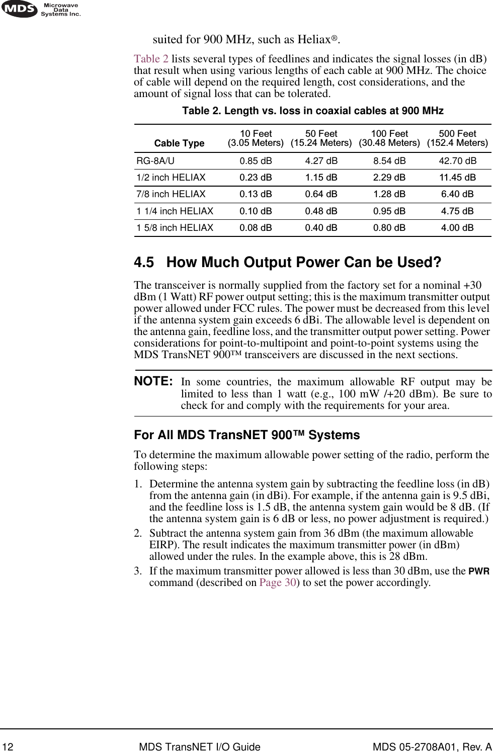
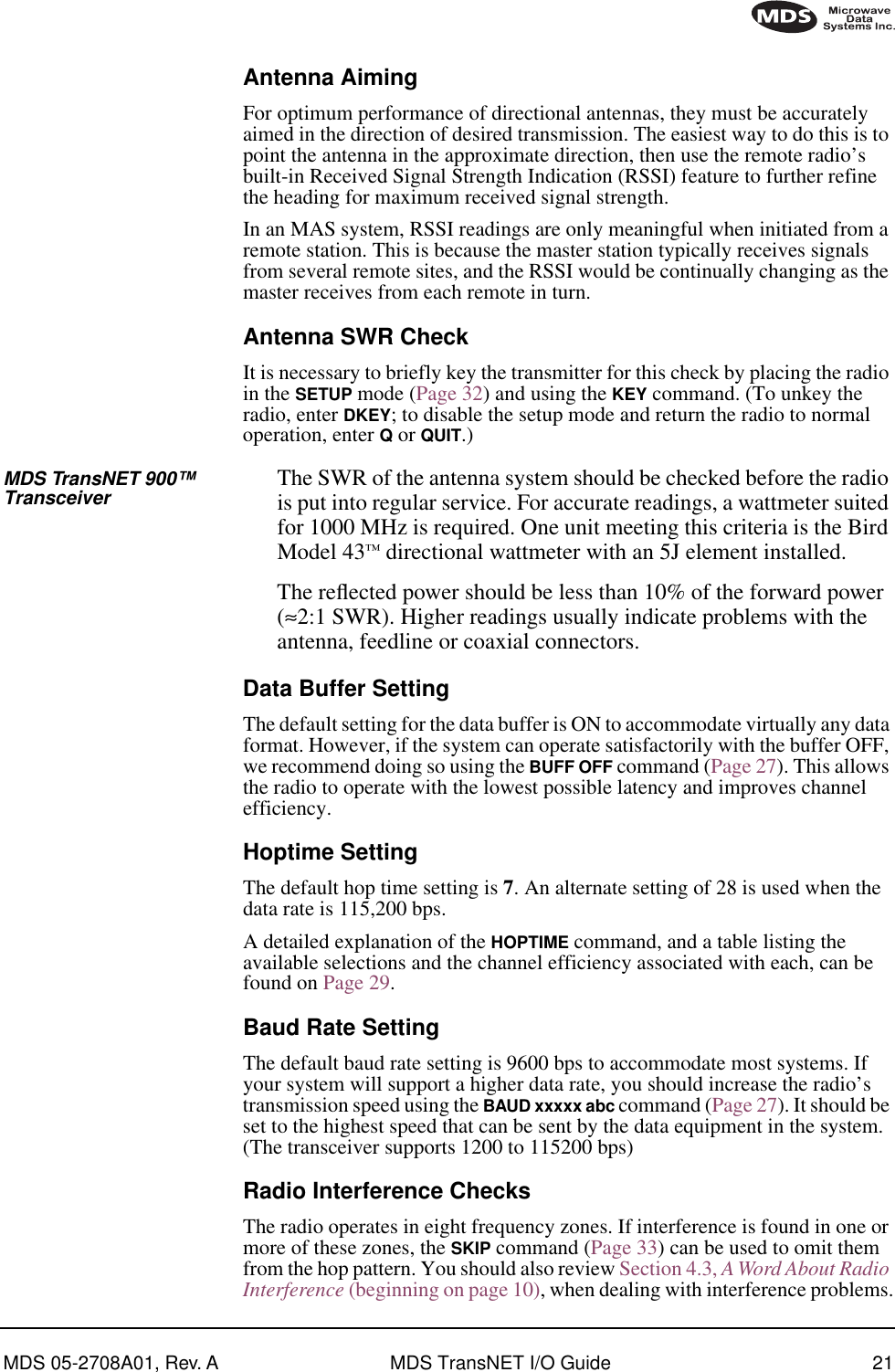
![MDS 05-2708A01, Rev. A MDS TransNET I/O Guide 33A timer keeps the Setup mode from accidentally leaving the system disabled. After 10 minutes the system behaves as if Q or QUIT had been entered, returning to normal operation.SHOW [PORT, DC, PWR]The SHOW command displays three types of information based on the command variables. These are:•PORT—Displays which connector port (RJ-11 or DB-9) is currently active for diagnostics and control.•DC—Displays DC input/output voltages.•PWR—Displays the actual (measured) RF power output in dBm. Unlike the PWR command, this command shows the actual level being measured, not the programmed RF power setting.SKIP [NONE, 1...8]This command sets or displays which, if any, of the eight 3.2 MHz TransNET 900 (128 frequency) zones will be skipped from the radio’s hopping sequence. Skipping zones is one way of dealing with constant interference on one or more frequencies. See Section 4.3 (Page 10) for more information on dealing with interference.Figure 18 shows the frequency range covered by each zone. The command parameter is either the keyword NONE or an undelimited string of up to seven digits where each digit 1...8 represents a corresponding zone to skip. (For zone parameter input, the digits can appear in any order and can be optionally separated by a blank space.) The SKIP command is read-only at remote radios. (Remotes must be synchronized with the master radio to read the skip status.)Invisible place holderFigure 18. Frequency zones for MDS TransNET 900 transceiversSSNRThis command displays the signal-to-noise ratio of the received signal expressed in dB. As used in this guide, the definition of signal-to-noise is based upon the signal level following equalization, for valid frames only. (A valid frame is defined as containing no more than one bit error, and belonging to a frame addressed for the receiving radio.) SNR is updated and latched for each valid frame received. A filter in the DSP tempers the effect of any sudden changes in the value.SNR output ranges from 10 dB to 33 dB. A value of 10 dB represents little or no signal. A value of 24 dB represents a very strong signal. For remote radios, a value of 0 is reserved to mean “no signal”; it is displayed whenever a remote is not in synchronization with the master station.When the SNR command is used, it causes the DIAG(NOSTIC) port to enter an update mode, and it will provide an updated signal-to-noise ratio every 1.6 seconds. It stays in this mode until the key is pressed.ZONE 1902.200to905.375ZONE 2905.400to908.575ZONE 3908.600to911.775ZONE 4911.800to914.975ZONE 5915.000to918.175ZONE 6918.200to921.375ZONE 7921.400to924.575ZONE 8924.600to927.775MDS TransNET 900 TRANSCEIVERENTER](https://usermanual.wiki/GE-MDS/TRANSNET900/User-Guide-224698-Page-41.png)
![34 MDS TransNET I/O Guide MDS 05-2708A01, Rev. ASREVThis command displays the software version currently loaded into the transceiver.A display of 06-3111A01, 3.5.1 is an example of the software version identifier.STATThis command is used to check alarm status.If an alarm does exist, a two-digit event code (00–31) is displayed and the event is identified as a “major” or “minor” alarm. A brief description of the event is also given.If more than one alarm exists, the word MORE appears at the bottom of the screen and additional alarms are viewed by pressing the key. Detailed descriptions of the alarm codes are provided in Table 9 on page 36.TTEMPThis command displays the internal temperature of the transceiver in degrees Celsius. (Note that the radio is specified to operate in an environment between –30 C° and +60 C°). This internal reading may be higher than the outside temperature by several degrees.TX [xxxx]This command sets or displays the test transmit frequency used in place of hopping whenever the radio is in Setup mode. The test transmit frequency can be reprogrammed to any value between 902.025 MHz and 927.975 MHz TransNET 900, inclusive. The factory default settings are listed below and have been selected to be non-intrusive to normal system operation.UNIT [10000–65000]This command sets the unit addressing for network-wide diagnostics. The unit address is factory programmed to the last four digits of the serial number. If re-programmed in the field, the entry must consist of five digits between 10000 and 65000.8.0 TROUBLESHOOTINGSuccessful troubleshooting of an MDS transceiver system is not difficult, but requires a logical approach. It is best to begin troubleshooting at the master station, as the rest of the system depends on the master for polling instructions and synchronization data. If the master station has problems, the operation of the entire network will be affected.When communication problems are found, it is good practice to begin by checking the simple things. All radios in the network must meet these basic requirements:Default Transmit Frequencies Master RemoteMDS TransNET 900927.975 MHz2400.08 MHz902.025 MHz2483.44 MHzENTER](https://usermanual.wiki/GE-MDS/TRANSNET900/User-Guide-224698-Page-42.png)