GE MDS TRANSNET900 MDS TransNet 900 User Manual 2708A TransNET Body
GE MDS LLC MDS TransNet 900 2708A TransNET Body
GE MDS >
users manual
MDS 05-2708A01 Rev. A
September 2001
TransNET 900“
Spread Spectrum Data Transceiver
MDS TransNET 900“

QUICK START GUIDE
Below are the basic steps for installing the transceiver. Detailed instructions are given in INSTALLA-
TION on page 24 of this guide.
1. Install and connect the antenna system to the radio
¥ Use good quality, low-loss coaxial cable. Keep the feedline as short as possible.
¥ Preset directional antennas in the direction of desired transmission.
2. Connect the data equipment to the radio s INTERFACE connector
¥ Connection to the radio must be made with a DB-9 Male connector. Connections for typical systems
are shown below.
¥ Connect only the required pins. Do not use a straight-through RS-232 cable with all pins wired.
¥ Verify the data equipment is configured as DTE. (By default, the radio is configured as DCE.)
3. Apply DC power to the radio
¥ Observe proper polarity. The red wire is the positive lead; the black is negative.
4. Verify proper operation by observing the LED display
¥ Refer to Table 4 on page 32 for a description of the status LEDs.
¥ Refine directional antenna headings for maximum receive signal strength using the RSSI command.

MDS 05-2708A01 Rev. A MDS TransNET 900 I/O Guide i
TABLE OF CONTENTS
1.0 ABOUT THIS MANUAL ............................................................... 9
2.0 PRODUCT DESCRIPTION ......................................................... 9
Transceiver Features....................................................................10
Model Configuration Codes ..........................................................10
2.1 Spread Spectrum Radios How Are They Different? ....................10
2.2 Typical Applications ........................................................................ 11
Multiple Address Systems (MAS) ................................................. 11
Simplex Peer-to-Peer ................................................................. 11
Point-to-Point System...................................................................12
Tail-End Link ( MAS Extension )...................................................12
Repeater System Traditional......................................................13
2.3 Accessories ....................................................................................14
3.0 GLOSSARY OF TERMS............................................................ 14
4.0 INSTALLATION PLANNING ...................................................... 17
4.1 General Requirements ................................................................... 17
4.2 Site Selection .................................................................................18
Terrain and Signal Strength .......................................................... 18
4.3 A Word About Radio Interference ...................................................20
4.4 Antenna & Feedline Selection ........................................................21
Antennas ......................................................................................21
Feedlines ......................................................................................22
4.5 How Much Output Power Can be Used? .......................................23
For All MDS TransNET 900“ Systems ........................................23
5.0 INSTALLATION.......................................................................... 24
5.1 Transceiver Installation ..................................................................25
5.2 Peer-to-Peer Systems ....................................................................27
Simplex Peer-to-Peer ...................................................................27
5.3 Tail-End Links .................................................................................27
Interface Wiring ............................................................................27
5.4 Repeaters Traditional Method .....................................................28
Antennas ......................................................................................28
System Addresses........................................................................29
Interface Wiring ............................................................................29
Interface Wiring ............................................................................29
Software Programming (TDD Command) ....................................30
Limitations of Single-Radio Repeaters .........................................30
5.5 Using the Radio s Sleep Mode ....................................................... 30

MDS 05-2708A01 Rev. A MDS TransNET 900 I/O Guide ii
Sleep Mode Example ...................................................................31
6.0 OPERATION.............................................................................. 31
6.1 Initial Start-up ................................................................................. 31
6.2 Performance Optimization ..............................................................32
Antenna Aiming ............................................................................ 32
Antenna SWR Check....................................................................32
Data Buffer Setting .......................................................................33
Hoptime Setting ............................................................................33
Baud Rate Setting ........................................................................33
Radio Interference Checks ...........................................................33
7.0 TRANCEIVER PROGRAMMING............................................... 33
7.1 Programming Methods ...................................................................34
7.2 Keyboard Commands ....................................................................34
Entering Commands.....................................................................35
7.3 Detailed Command Descriptions ....................................................38
ADDR [1...65000] .........................................................................38
AMASK [0000 0000—FFFF FFFF] ................................................39
ASENSE [HI/LO]...........................................................................39
BAUD [xxxxx abc].........................................................................39
BUFF [ON, OFF]...........................................................................40
CTS [0—255] .................................................................................40
CTSHOLD [0-6000] ......................................................................41
DEVICE [DCE, CTS KEY] ...........................................................41
DMGAP [xx]..................................................................................42
HOPTIME .....................................................................................42
MODE [M, R, R-M] .......................................................................43
OWM [xxxxx] ................................................................................43
OWN [xxxxx].................................................................................43
PWR [xx—30].................................................................................43
RSSI .............................................................................................43
RTU [ON/OFF/0-80]......................................................................44
RX [xxxx] ......................................................................................44
RXTOT [NONE, 0—1440] ..............................................................45
SEND [n, -n, +n] ...........................................................................45
SETUP..........................................................................................46
SHOW [PORT, DC, PWR] ............................................................47
SKIP [NONE, 1...8] .......................................................................47
SSNR............................................................................................47
SREV............................................................................................48
STAT .............................................................................................48
TTEMP .........................................................................................48
TX [xxxx].......................................................................................48
UNIT [10000—65000] ....................................................................49
8.0 TROUBLESHOOTING............................................................... 49
8.1 LED Indicators ................................................................................49
8.2 Alarm Codes ...................................................................................50
MDS 05-2708A01 Rev. A MDS TransNET 900 I/O Guide iii
Checking for Alarms STAT command ........................................50
Major Alarms vs. Minor Alarms .....................................................50
Alarm Code Definitions.................................................................50
8.3 Troubleshooting Chart ....................................................................52
9.0 TECHNICAL REFERENCE ....................................................... 52
9.1 Technical Specifications .................................................................52
9.2 Data Interface Connections (DB-9) ................................................ 54
9.3 dBm-Watts-Volts Conversion Chart ...............................................57
IN CASE OF DIFFICULTY... ........................................................... 65
Copyright Notice
This Installation and Operation Guide and all software described herein
are protected by copyright: 2001 Microwave Data Systems Inc. All
rights reserved.
Microwave Data Systems reserves its right to correct any errors and
omissions in this manual.
Operational Safety Notices
The radio equipment described in this guide emits radio frequency
energy. Although the power level is low, the concentrated energy from
a directional antenna may pose a health hazard.
Do not allow people to
come closer than 2 meters (6 feet) to the antenna when the trans-
mitter is operating.
This manual is intended to guide a professional installer in installing,
operating and performing basic system maintenance on the described
equipment.
ISO 9001 Registration
Microwave Data Systems adheres to the internationally-accepted ISO
9001 quality system standard.
MDS Quality Policy Statement
We, the employees of Microwave Data Systems, are committed to
understanding and exceeding our customer s needs and expectations.
¥ We appreciate our customers patronage. They are our business.
¥ We promise to serve them and anticipate their needs.
¥ We are comitted to providing solutions that are cost effective,
innovative and reliable, with consistently high levels of quality.
RF Exposure

MDS 05-2708A01 Rev. A MDS TransNET 900 I/O Guide iv
¥ We are committed to the continuous improvement of all of our
systems and processes, to improve product quality and increase
customer satisfaction.
FM/UL/CSA Notice
MDS TransNET 900“ When Approved
This product is available for use in Class I, Division 2, Groups A, B,
C & D Hazardous Locations. Such locations are defined in Article 500
of the National Fire Protection Association (NFPA) publication NFPA
70, otherwise known as the National Electrical Code.
The transceiver has been recognized for use in these hazardous locations
by three independent agencies Underwriters Laboratories (UL), Fac-
tory Mutual Research Corporation (FMRC) and the Canadian Standards
Association (CSA). The UL certification for the transceiver is as a Rec-
ognized Component for use in these hazardous locations, in accordance
with UL Standard 1604. The FMRC Approval is in accordance with
FMRC Standard 3611. The CSA Certification is in accordance with
CSA STD C22.2 No. 213-M1987.
FM/UL/CSA Conditions of Approval:
The transceiver is not acceptable as a stand-alone unit for use in the haz-
ardous locations described above. It must either be mounted within
another piece of equipment which is certified for hazardous locations, or
installed within guidelines, or conditions of approval, as set forth by the
approving agencies. These conditions of approval are as follows:
1. The transceiver must be mounted within a separate enclosure which
is suitable for the intended application.
2. The antenna feedline, DC power cable and interface cable must be
routed through conduit in accordance with the National Electrical
Code.
3. Installation, operation and maintenance of the transceiver should be
in accordance with the transceiver’s installation manual, and the
National Electrical Code.
4. Tampering or replacement with non-factory components may
adversely affect the safe use of the transceiver in hazardous loca-
tions, and may void the approval.
5. When installed in a Class I, Div. 2, Groups A, B, C or D hazardous
location, observe the following:
WARNING EXPLOSION HAZARD
Do not disconnect equip-
ment unless power has been switched off or the area is know to be
non-hazardous.

MDS 05-2708A01 Rev. A MDS TransNET 900 I/O Guide v
Refer to Articles 500 through 502 of the National Electrical Code
(NFPA 70) for further information on hazardous locations and approved
Division 2 wiring methods.
FCC Part 15 Notice
The MDS TransNET 900“ transceivers comply with Part 15 of the
FCC Rules. Operation is subject to the following two conditions: (1) this
device may not cause harmful interference, and (2) this device must
accept any interference received, including interference that may cause
undesired operation.
This device is specifically designed to be used under Section 15.247 of
the FCC Rules and Regulations. Any unauthorized modification or
changes to this device without the express approval of Microwave Data
Systems may void the user s authority to operate this device.
Furthermore, this device is indented to be used only when installed in
accordance with the instructions outlined in this manual. Failure to
comply with these instructions may also void the user s authority to
operate this device.
Revision Notice
While every reasonable effort has been made to ensure the accuracy of
this manual, product improvements may result in minor differences
between the manual and the product shipped to you. If you have addi-
tional questions or need an exacts specification for a product, please
contact our Customer Service Team using the information at the back of
this guide. In addition, manual updates can often be found on the MDS
Web site at www.microwavedata.com.
Limited Modular Approval Notice
MDS TransNET radios are intended for use only inside an enclosure that
is fully compliant to FCC Part 15 requirements. These enclosures have
been tested with MDS radio products and meet the unintentional radi-
ator requirements as set forth by the FCC. MDS certifies that any future
enclosures offered with these products will meet the appropriate
requirements and will not offer the products to end users as board-only
solutions.

vi MDS TransNET 900 I/O Guide MDS 05-3301A01, Rev. A
MDS 05-2708A01, Rev. A MDS TransNET I/O Guide 1
1.0 ABOUT THIS MANUAL
This guide presents installation and operating instructions for the
MDS TransNET 900™
transceivers. Following installation, we suggest
keeping this guide near the equipment for future reference.
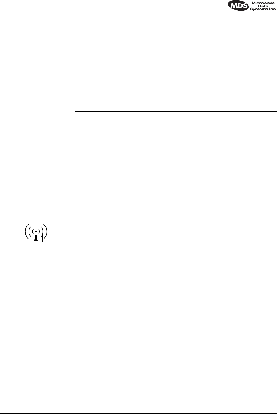
2.0 PRODUCT DESCRIPTION
The transceiver, shown in Figure 1, is a spread spectrum radio designed for
license-free operation in the 900 MHz frequency band. Employing
microprocessor control and Digital Signal Processing (DSP) technology, they
are highly reliable for long-distance communications, even in the presence of
weak signals or interference.
DSP technology also makes it possible to obtain information about radio
operation and troubleshoot problems, without going to the remote radio site.
Using the appropriate software at the master station, diagnostic data can be
obtained on any DSP radio in the system, even while payload data is being
transmitted.
DSP technology also makes it possible to obtain information about radio
operation and troubleshoot problems, without going to the remote radio site.
Using the appropriate software at the master station, diagnostic data can be
obtained on any DSP radio in the system, even while payload data is being
transmitted. The TransNET 900™ is housed in a compact and rugged die-cast
aluminum case that need only be protected from direct exposure to the
weather. It contains a single printed circuit board with all necessary
components for radio operation. No jumper settings or adjustments are
required to configure the radio for operation.
Figure 1. MDS TransNET 900 Transceiver
Invisible place holder
Transceiver Features
Listed below are several key features of the MDS TransNET 900™
transceivers. These are designed to ease the installation and configuration of
the radio, while retaining the ability to make changes in the future.
• 1,028 frequencies over 902–928 MHz, subdivided into eight
frequency zones
• Configurable operating zones to omit frequencies with constant
interference
• 65,000 available network addresses

2 MDS TransNET I/O Guide MDS 05-2708A01, Rev. A
•Network-wide configuration from the master station; eliminates most
trips to remote sites
•Data transparency–ensures compatibility with virtually all
asynchronous SCADA system RTUs
•Peak-hold RSSI, averaged over eight hop cycles
•Operation at up to 115,200 bps continuous data flow
•Same hardware for master or remote configuration
•Data latency typically less than 10 ms
•Supports EIA-232 (formerly called RS-232) and RS-485 user
interface
•Low current consumption–5 mA or less average draw in “sleep”
mode.
Model Configuration Codes
The radio model number is printed on the end of the radio enclosure, and
provides key information about how the radio was configured when it left the
factory. See Figure 2 for an explanation of the model number characters.
Graphic is pending.
Figure 2. MDS TransNET 900™ transceiver model configuration codes
Invisible place holder
2.1 Spread Spectrum Radios—How Are They
Different?
The main difference between a traditional (licensed) radio system and the
MDS TransNET 900™ transceivers is that these units “hop” from channel to
channel many times per second using a specific hop pattern applied to all
radios in the network. A distinct hopping pattern is provided for each of the
65,000 available network addresses, thereby minimizing the chance of
interference with other spread spectrum systems. In the USA, and certain other
countries, no license is required to install and operate this type of radio system.
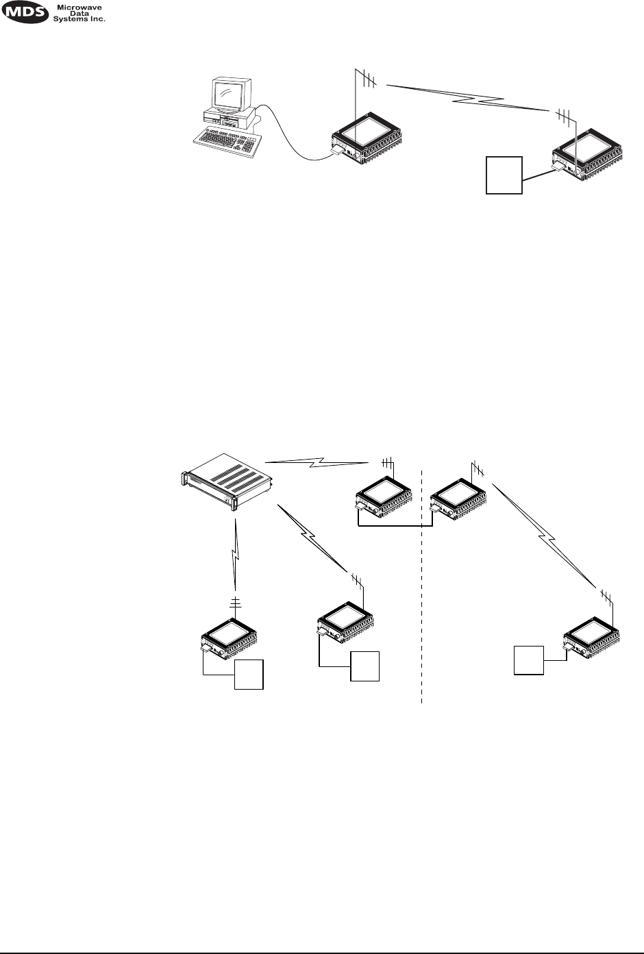
2.2 Typical Applications
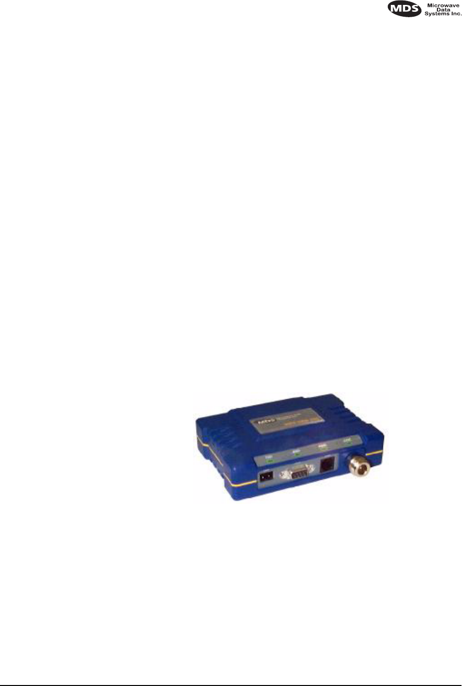
Multiple Address Systems (MAS)
This is the most common application of the MDS TransNET 900™
transceivers. It consists of a central control station (master) and two or more
associated remote units, as shown in Figure 3. An MAS network provides
communications between a central host computer and remote terminal units
(RTU’s) or other data collection devices. The operation of the radio system is
transparent to the computer equipment. When used in this application, the
transceiver provides an excellent alternative to traditional (licensed) MAS
radio systems.
THIS INFORMATION IS
SUBJECT TO CHANGE.
DO NOT USE FOR
PRODUCT ORDERING.
MDS 05-2708A01, Rev. A MDS TransNET I/O Guide 3
Invisible place holder
Figure 3. Typical MAS network
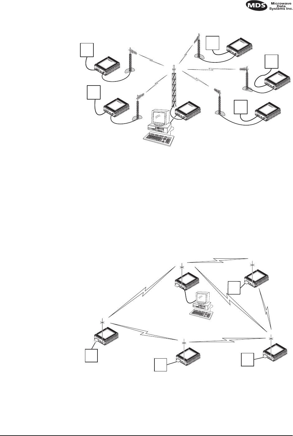
Simplex “Peer-to-Peer”
Peer-to-peer communication is possible using the transceiver’s simplex mode.
With this arrangement (Figure 4), two or more remote units can share
information by direct communication with each other in addition to
communicating with a central master radio. This is possible because the
transmit and receive frequencies for each hop channel are the same at each
radio when simplex mode is enabled. If adequate transmission paths exist, each
radio can communicate with all other units in the network. Additional details
for peer-to-peer systems are provided in Section 5.2 (Page 16).
Invisible place holder
Figure 4. Typical simplex “peer-to-peer” network
Point-to-Point System
A point-to-point configuration (Figure 5) is a simple arrangement consisting of
just two radios—a master and a remote. This provides a simplex or half-duplex
communications link for the transfer of data between two locations.
–
MDS 9810
DATA TRANSCEIVER
MDS 9810
DATA INTERFACEIDIAG
13.8 VDC
PWRSYNCTXDRXD
ANTENNA
+ –
–
MDS 9810
DATA TRANSCEIVER
MDS 9810
DATA INTERFACEIDIAG
13.8 VDC
PWRSYNCTXDRXD
ANTENNA
+ –
–
MDS 9810
DATA TRANSCEIVER
MDS 9810
DATA INTERFACEIDIAG
13.8 VDC
PWRSYNCTXDRXD
ANTENNA
+ –
–
MDS 9810
DATA TRANSCEIVER
MDS 9810
DATA INTERFACEIDIAG
13.8 VDC
PWRSYNCTXDRXD
ANTENNA
+ –
–
MDS 9810
DATA TRANSCEIVER
MDS 9810
DATA INTERFACEIDIAG
13.8 VDC
PWRSYNCTXDRXD
ANTENNA
+ –
–
MDS 9810
DATA TRANSCEIVER
MDS 9810
DATA INTERFACEIDIAG
13.8 VDC
PWRSYNCTXDRXD
ANTENNA
+ –
REMOTE RADIO
REMOTE RADIO MASTER RADIO
HOST SYSTEM
REMOTE RADIO
REMOTE RADIO
REMOTE RADIO
RTU
RTU
RTU
RTU
RTU
RTU RTU
PEER-TO-PEER PEER-TO-PEER
RTU
RTU
REMOTE RADIO
MASTER RADIO
HOST SYSTEM
PEER-TO-PEER
REMOTE RADIO REMOTE RADIO
REMOTE RADIO
4 MDS TransNET I/O Guide MDS 05-2708A01, Rev. A
Invisible place holder
Figure 5. Typical point-to-point link
Tail-End Link
( MAS Extension )
A tail-end link can be used to extend the range of a traditional (licensed) MAS
system. This might be required if an outlying site is blocked from the MAS
master station by a natural or man-made obstruction. In this arrangement, an
MDS TransNET 900™ radio links the outlying remote site into the rest of a
licensed MAS system by sending data from that site to an associated MDS
TransNET 900™ installed at one of the licensed remote sites. (See Figure 6).
As the data from the outlying site is received at the licensed remote site, it is
transferred to the licensed radio (via a local cable connection) and is then
transmitted to the MAS master station in the usual manner. Additional details
for tail-end links are given in Section 5.3 (Page 17).
Invisible place holder
Figure 6. Typical tail-end link arrangement
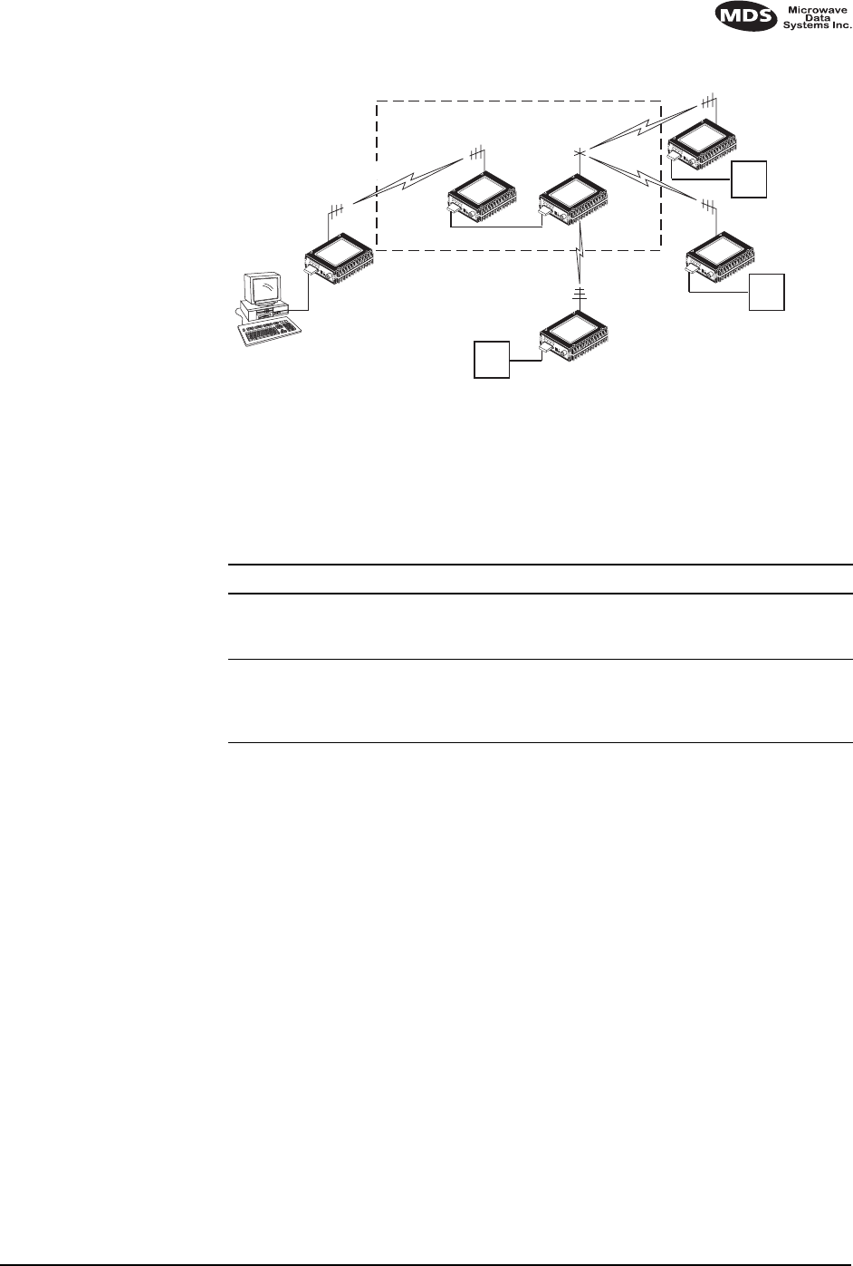
Repeater System—Traditional
Although the range between MDS TransNET 900™ radios is typically 10
miles over average terrain, it is possible to extend the range considerably by
connecting two units together at one site in a “back-to-back” fashion to form a
repeater, as shown in Figure 7. Additional details for repeater systems are
given in Section 5.4 (Page 17).
REMOTE RADIO
RTU
MASTER RADIO
HOST
SYSTEM
POINT
-T
O-POINT
SPREAD SPECTRUM
LINK
REMOTE
RADIO
MASTER
STATION
MAS SYSTEM (LICENSED OR UNLICENSED) MDS 9810/9820 LINK TO AN OUTLYING SITE
REPEATER
RTU
REMOTE
RADIO
Null-Modem
Cable
RTU
RTU
MDS 9810 / 9820
MASTER RADIO
MDS 9810 / 9820
REMOTE RADIO
REMOTE
RADIO
MDS 05-2708A01, Rev. A MDS TransNET I/O Guide 5
Invisible place holder
Figure 7. Typical repeater system configuration
2.3 Accessories
The MDS TransNET 900
transceivers can be used with one or more of the
accessories listed in Table 1. Contact the factory for ordering details.
3.0 GLOSSARY OF TERMS
If you are new to spread spectrum radio, some of the terms used in this guide
may be unfamiliar. The following glossary explains many of these terms and
will prove helpful in understanding the operation of the transceiver.
Antenna System Gain—A figure, normally expressed in dB, representing the
power increase resulting from the use of a gain-type antenna. System losses
(from the feedline and coaxial connectors, for example) are subtracted from
this figure to calculate the total antenna system gain.
Bit—The smallest unit of digital data, often represented by a one or a zero.
Eight bits (plus start, stop, and parity bits) usually comprise a byte.
Bits-per-second—See BPS.
BPS—Bits-per-second. A measure of the information transfer rate of digital
data across a communication channel.
Byte—A string of digital data usually made up of eight data bits and start, stop,
and parity bits.
Decibel (dB)—A measure of the ratio between two signal levels. Frequently
used to express the gain (or loss) of a system.
RTU
RTU
REPEATER LINK
Null-Modem Cable
RTU
MASTER
RADIO
REMOTE RADIO
REMOTE RADIO
REMOTE RADIO
REMOTE RADIO
MASTER
RADIO
HOST COMPUTER
POINT-TO-POINT LINK
Table 1. Accessories
Accessory Description MDS P/N
RTU Simulator Test unit that simulates data from a remote
terminal unit. Comes with polling software that runs
on a PC. Useful for testing radio operation.
03-2512A01
EIA-232 to
EIA-422
Converter
External adapter that converts the radio’s DATA
INTERFACE connector to EIA-422 compatible
signaling. May be required for long cable runs (over
50 feet/15 meters).
03-2358A01

6 MDS TransNET I/O Guide MDS 05-2708A01, Rev. A
Data Circuit-terminating Equipment—See DCE.
Data Communications Equipment—See DCE.
Data Terminal Equipment—See DTE.
dBi—Decibels referenced to an “ideal” isotropic radiator in free space.
Frequently used to express antenna gain.
dBm—Decibels referenced to one milliwatt. An absolute unit used to measure
signal power, as in transmitter power output, or received signal strength.
DCE—Data Circuit-terminating Equipment (or Data Communications
Equipment). In data communications terminology, this is the “modem” side of
a computer-to-modem connection. By default, MDS TransNET 900™
transceivers are set as DCE devices.
Digital Signal Processing—See DSP.
DSP—Digital Signal Processing. In the MDS TransNET 900™ transceivers,
the DSP circuitry is responsible for the most critical real-time tasks; primarily
modulation, demodulation, and servicing of the data port.
DTE—Data Terminal Equipment. A device that provides data in the form of
digital signals at its output. Connects to the DCE device.
Equalization—The process of reducing the effects of amplitude, frequency or
phase distortion with compensating networks.
Fade Margin—The greatest tolerable reduction in average received signal
strength that will be anticipated under most conditions. Provides an allowance
for reduced signal strength due to multipath, slight antenna movement or
changing atmospheric losses. A fade margin of 20 to 30 dB is usually sufficient
in most systems.
Frame—A segment of data that adheres to a specific data protocol and contains
definite start and end points. It provides a method of synchronizing
transmissions.
Frequency Hopping—The spread spectrum technique used by the MDS
TransNET 900™ transceivers, where two or more associated radios change
their operating frequencies several times per second using a set pattern. Since
the pattern appears to jump around, it is said to “hop” from one frequency to
another.
Frequency Zone—The transceivers use up to 1,028 discrete channels in the
902 to 928 MHz spectrums. A group of 16 channels is referred to as a zone.
The transceivers use five to eight frequency zones.
Hardware Flow Control—A transceiver feature used to prevent data buffer
overruns when handling high-speed data from the RTU or PLC. When the
buffer approaches overflow, the radio drops the clear-to-send (CTS) line,
which instructs the RTU or PLC to delay further transmission until CTS again
returns to the high state.
Host Computer—The computer installed at the master station site, which
controls the collection of data from one or more remote sites.
Latency—The delay (usually expressed in milliseconds) between when data is
applied to TXD (Pin 2) at one radio, until it appears at RXD (Pin 3) at the other
radio.
MAS—Multiple Address System. A radio system where a central master
station communicates with several remote stations for the purpose of gathering
telemetry data. Figure 3 on page 3 shows an example of an MAS system.

MDS 05-2708A01, Rev. A MDS TransNET I/O Guide 7
Master (Station)—The one radio transceiver in a spread spectrum network that
automatically provides synchronization information to one or more associated
remote transceivers. A radio may be programmed for either master or remote
mode using software commands. See Section 7.0,
TRANCEIVER
PROGRAMMING
(beginning on page 22).
MCU—Microcontroller Unit. This is the processor responsible for controlling
system start-up, synthesizer loading, hop timing, and key-up control.
Microcontroller Unit—See MCU.
Mode—This refers to the programmed function of an MDS spread spectrum
radio—master or remote. (See also Remote Station and Master Station.)
Multiple Address System (MAS)—See Point-Multipoint System.
Network Address—User-selectable number between 1 and 65000 that is used
to identify a group of transceivers that form a communications network. The
master and all remotes within a given system must have the same network
address.
Point-Multipoint System—A radio communications network or system
designed with a central control station that exchanges data with a number of
remote locations equipped with terminal equipment.
Poll—A request for data issued from the host computer (or master PLC) to a
remote radio.
PLC—Programmable Logic Controller. A dedicated microprocessor
configured for a specific application with discrete inputs and outputs. It can
serve as a host or as an RTU.
Remote Radio—A radio in a spread spectrum network that communicates with
an associated master station. A radio may be programmed for either master or
remote mode using software commands. See Section 7.0,
TRANCEIVER
PROGRAMMING
(beginning on page 22).
Remote Terminal Unit—See RTU.
RTU—Remote Terminal Unit. A data collection device installed at a remote
radio site.
SCADA—Supervisory Control And Data Acquisition. An overall term for the
functions commonly provided through an MAS radio system.
Standing Wave Ratio—See SWR.
SWR—Standing Wave Ratio. A parameter related to the ratio between
forward transmitter power and the reflected power from the antenna system.
As a general guideline, reflected power should not exceed 10% of the forward
power (
≈
2:1 SWR).
Zone—See Frequency Zone.
4.0 INSTALLATION PLANNING
The installation of the radio is not difficult, but it does require some planning
to ensure station reliability and efficiency. This section provides tips for
selecting an appropriate site, choosing an antenna system, and reducing the
chance of harmful interference.
8 MDS TransNET I/O Guide MDS 05-2708A01, Rev. A
4.1 General Requirements
There are three main requirements for installing the radio—adequate and
stable primary power, a good antenna system, and the correct interface
between the transceiver and the data device.
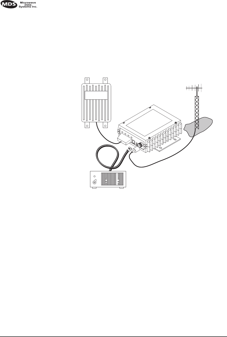
Figure 8 shows a typical remote station arrangement. At a remote station, a
directional antenna is normally used, and a Remote Terminal Unit (RTU) or
other telemetry equipment replaces the host computer normally used in a
master station.
Invisible place holder
Figure 8. Typical remote station arrangement
4.2 Site Selection
For a successful installation, careful thought must be given to selecting proper
sites for the master and remote stations. Suitable sites should provide:
•Protection from direct weather exposure
•A source of adequate and stable primary power
•Suitable entrances for antenna, interface or other required cabling
•Antenna location that provides an unobstructed transmission path in
the direction of the associated station
(
s
)
These requirements can be quickly determined in most cases. A possible
exception is the last item—verifying that an unobstructed transmission path
exists. Radio signals travel primarily by line-of-sight, and obstructions
between the sending and receiving stations will affect system performance. If
you are not familiar with the effects of terrain and other obstructions on radio
transmission, the discussion below will provide helpful background.
Terrain and Signal Strength
While the 900 MHz band offers many advantages over VHF and lower UHF
frequencies for data transmission, it is also more prone to signal attenuation
from obstructions such as terrain, foliage or buildings in the transmission path.
13.8 VDC
POWER
CABLE
13.8 VDC
POWER
SUPPLY
REMOTE TERMINAL
UNIT ANTENNA SYSTEM
(Directional Type
Normally Used)
LOW-LOSS FEEDLINE
REMOTE RADIO

MDS 05-2708A01, Rev. A MDS TransNET I/O Guide 9
A line-of-sight transmission path between the master station and its associated
remote site
(
s
)
is highly desirable and provides the most reliable
communications link. A line-of-sight path can often be achieved by mounting
the station antenna on a tower or other elevated structure that raises it to a level
sufficient to clear surrounding terrain and other obstructions.
The importance of a clear transmission path relates closely to the distance to
be covered by the system. If the system is to cover only a limited geographic
area, say up to 3 miles (4.8 km) for the MDS TransNET 900™, then some
obstructions in the transmission path can usually be tolerated with minimal
impact. For longer range systems, any substantial obstruction in the
transmission path could compromise the performance of the system, or block
transmission entirely.
Much depends on the minimum signal strength that can be tolerated in a given
system. Although the exact figure will differ from one system to another, a
Received Signal Strength Indication (RSSI) of –90 dBm or stronger will
provide acceptable performance in many systems. While the equipment will
work at lower signal strengths, this provides a “fade margin” to account for
variations in signal strength which may occur from time-to-time.
Conducting a Site Survey
If you are in doubt about the suitability of the radio sites in your system, it is
best to evaluate them before a permanent installation is begun. This can be
done with an on-the-air test (preferred method); or indirectly, using path-study
software.
An on-the-air test is preferred because it allows you to see firsthand the factors
involved at an installation site and to directly observe the quality of system
operation. Even if a computer path study was conducted earlier, this test should
be done to verify the predicted results.
The test can be performed by first installing a radio and antenna at the proposed
master station site and then visiting each remote site with a transceiver and a
hand-held antenna. (An RTU simulator—MDS Part No. 03-2512A01—can be
connected to each radio in the network to simulate data during this test.)
With the hand-held antenna positioned near the proposed mounting spot, a
technician can check for synchronization with the master station (shown by a
lit
SYNC
lamp on the front panel) and measure the reported RSSI value. If
adequate signal strength cannot be obtained, it may be necessary to mount the
station antennas higher, use higher gain antennas, or select a different site. To
prepare the equipment for an on-the-air test, follow the general installation
procedures given in this guide and become familiar with the operating
instructions given in Section 6.0, beginning on Page 20.
If time is short, and a site survey is impractical, a computer path study is a good
alternative. Factors such as terrain, distance, transmitter power, receiver
sensitivity, and other conditions are taken into account to predict the
performance of a proposed system. Contact MDS for more information on path
study services.

10 MDS TransNET I/O Guide MDS 05-2708A01, Rev. A
4.3 A Word About Radio Interference
The MDS TransNET 900™ transceivers share frequency spectrums with other
services and other Part 15 (unlicensed) devices in the USA. As such, near
100% error free communications may not be achieved in a given location, and
some level of interference should be expected. However, the radio’s flexible
design and hopping techniques should allow adequate performance as long as
care is taken in choosing station location, configuration of radio parameters
and software/protocol techniques.
In general, keep the following points in mind when setting up your
communications network:
1. Systems installed in rural areas are least likely to encounter interference;
those in suburban and urban environments are more likely to be affected
by other devices operating in the license-free frequency band and by
adjacent licensed services.
2. If possible, use a directional antenna at remote sites. Although these antennas
may be more costly than omnidirectional types, they confine the transmission
and reception pattern to a comparatively narrow lobe, which minimizes
interference to (and from) stations located outside the pattern. (The use of a
directional antenna may not be possible in a simplex peer-to-peer network,
where all remotes are designed to communicate with one another.)
3. If interference is suspected from a nearby licensed system (such as a paging
transmitter), it may be helpful to use horizontal polarization of all antennas
in the network. Because most other services use vertical polarization in this
band, an additional 20 dB of attenuation to interference can be achieved by
using horizontal polarization.
4. Multiple MDS TransNET 900™ systems can co-exist in proximity to each
other with only very minor interference as long as they are each assigned a
unique network address. Each network address has a different hop pattern.
5. If constant interference is present in a particular frequency zone, it may be
necessary to “lock out” that zone from the radio’s hopping pattern. The radio
includes built-in software to help users remove blocked frequency zones
from its hopping pattern. Refer to the discussion of the
SKIP
(
Page 33
)
command for more information.
6. If interference problems persist even after removing blocked zones, try
reducing the length of data streams. Groups of short data streams have a
better chance of getting through in the presence of interference than do long
streams.
7. The power output of all radios in a system should be set for the lowest level
necessary for reliable communications. This lessens the chance of causing
unnecessary interference to nearby systems.
4.4 Antenna & Feedline Selection
Antennas
The equipment can be used with a number of antennas. The exact style used
depends on the physical size and layout of a system. Contact your MDS
representative for specific recommendations on antenna types and hardware
sources.
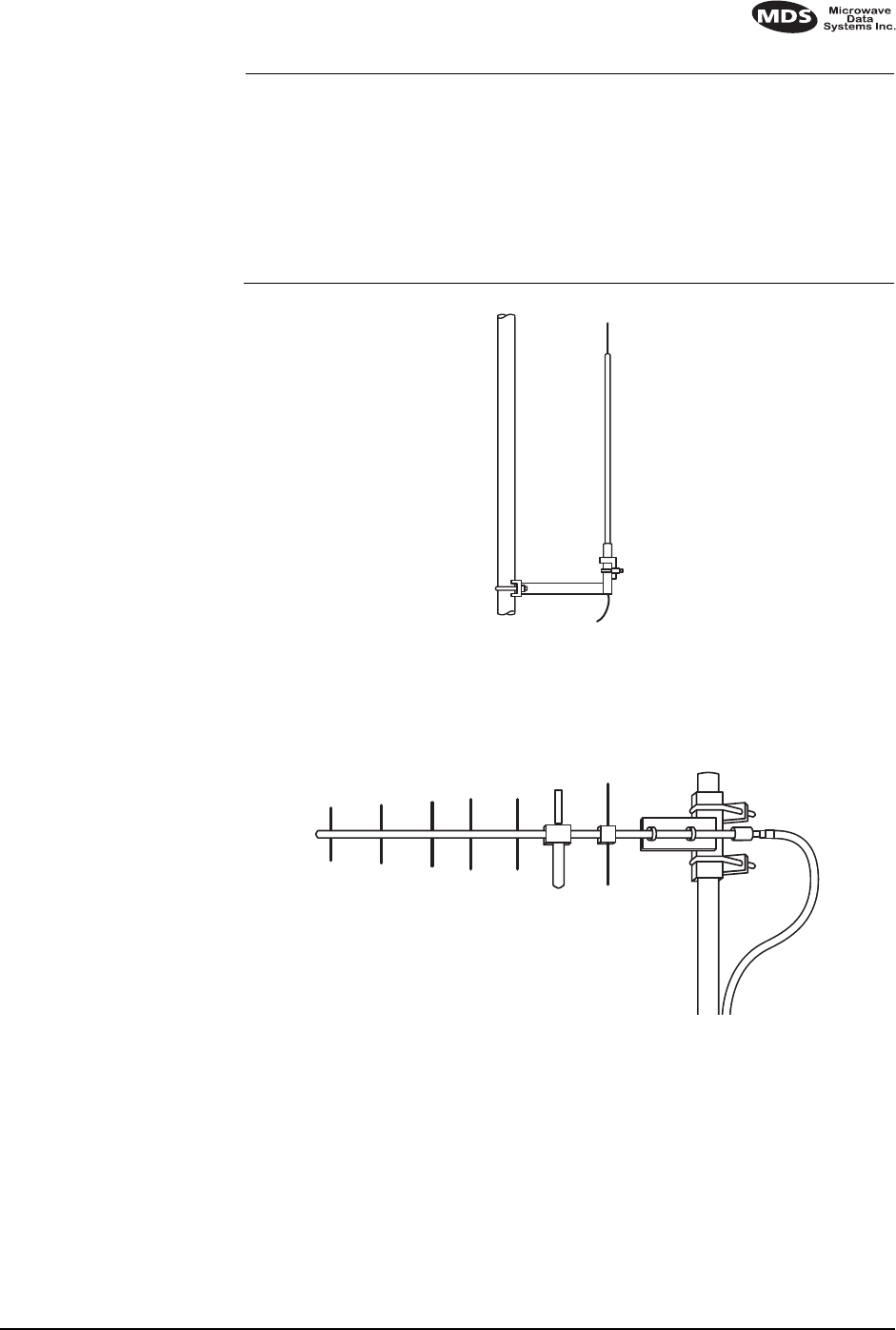
In general, an omnidirectional antenna (Figure 9 and Figure 10) is used at the
master station site in an MAS system. This provides equal coverage to all of
the remote sites.
MDS 05-2708A01, Rev. A MDS TransNET I/O Guide 11
NOTE: Antenna polarization is important. If the wrong polarization is used,
a signal reduction of 20 dB or more will result. Most systems using
a gain-type omnidirectional antenna at the master station employ
vertical polarization of the signal; therefore, the remote antenna(s)
must also be vertically polarized (elements oriented perpendicular to
the horizon).
When required, horizontally polarized omnidirectional antennas are
also available. Contact your MDS representative for details.
Invisible place holder
Figure 9. Omnidirectional antenna for MDS TransNET 900™ transceiver
At remote sites and point-to-point systems, a directional Yagi antenna
(Figure 10), is generally recommended to minimize interference to and from
other users. Antennas are available from a number of manufacturers.
Invisible place holder
Figure 10. Typical Yagi antenna (mounted to mast)
Feedlines
The choice of feedline used with the antenna should be carefully considered.
Poor-quality coaxial cables should be avoided, as they will degrade system
performance for both transmission and reception. The cable should be kept as
short as possible to minimize signal loss.
MDS TransNET
900™Transceiver For cable runs of less than 20 feet (6 meters), or for short range
transmission, an inexpensive type such as Type RG8A/U may be
acceptable. Otherwise, we recommend using a low-loss cable type

12 MDS TransNET I/O Guide MDS 05-2708A01, Rev. A
suited for 900 MHz, such as Heliax®.
Table 2 lists several types of feedlines and indicates the signal losses (in dB)
that result when using various lengths of each cable at 900 MHz. The choice
of cable will depend on the required length, cost considerations, and the
amount of signal loss that can be tolerated.
4.5 How Much Output Power Can be Used?
The transceiver is normally supplied from the factory set for a nominal +30
dBm (1 Watt) RF power output setting; this is the maximum transmitter output
power allowed under FCC rules. The power must be decreased from this level
if the antenna system gain exceeds 6 dBi. The allowable level is dependent on
the antenna gain, feedline loss, and the transmitter output power setting. Power
considerations for point-to-multipoint and point-to-point systems using the
MDS TransNET 900™ transceivers are discussed in the next sections.
NOTE: In some countries, the maximum allowable RF output may be
limited to less than 1 watt (e.g., 100 mW /+20 dBm). Be sure to
check for and comply with the requirements for your area.
For All MDS TransNET 900™ Systems
To determine the maximum allowable power setting of the radio, perform the
following steps:
1. Determine the antenna system gain by subtracting the feedline loss (in dB)
from the antenna gain (in dBi). For example, if the antenna gain is 9.5 dBi,
and the feedline loss is 1.5 dB, the antenna system gain would be 8 dB. (If
the antenna system gain is 6 dB or less, no power adjustment is required.)
2. Subtract the antenna system gain from 36 dBm (the maximum allowable
EIRP). The result indicates the maximum transmitter power (in dBm)
allowed under the rules. In the example above, this is 28 dBm.
3. If the maximum transmitter power allowed is less than 30 dBm, use the PWR
command (described on
Page 30
) to set the power accordingly.
Table 2. Length vs. loss in coaxial cables at 900 MHz
Cable Type 10 Feet
(3.05 Meters)
50 Feet
(15.24 Meters)
100 Feet
(30.48 Meters)
500 Feet
(152.4 Meters)
RG-8A/U 0.85 dB 4.27 dB 8.54 dB 42.70 dB
1/2 inch HELIAX 0.23 dB 1.15 dB 2.29 dB 11.45 dB
7/8 inch HELIAX 0.13 dB 0.64 dB 1.28 dB 6.40 dB
1 1/4 inch HELIAX 0.10 dB 0.48 dB 0.95 dB 4.75 dB
1 5/8 inch HELIAX 0.08 dB 0.40 dB 0.80 dB 4.00 dB

MDS 05-2708A01, Rev. A MDS TransNET I/O Guide 13
For convenience, Table 3 lists several antenna system gains and shows the
maximum allowable power setting of the radio. Note that a gain of 6 dB or less
entitles you to operate the radio at full power output—30 dBm (1 watt).
* Most antenna manufacturers rate antenna gain in dBd in their
literature. To convert to dBi, add 2.15 dB.
† Feedline loss varies by cable type and length. To determine the
loss for common lengths of feedline, see Table 2 on page 12 for
the MDS TransNET 900™ transceiver.
5.0 INSTALLATION
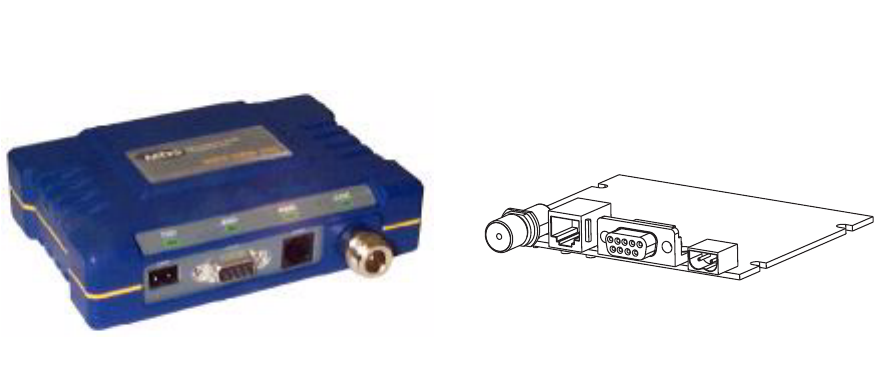
Figure 11 shows a typical transceiver product shipment (board versions of
OEM shipments will differ). Check the contents against the packing list
secured to the outside of the shipping box. Accessories and spare parts kits, if
any, are wrapped separately. Inspect all items for signs of damage and save all
packing materials for possible re-shipment.
Table 3. Antenna system gain vs. power output setting (USA)
Antenna System Gain
(Antenna Gain in dBi*
minus Feedline Loss in dB†)
Maximum Power
Setting
(in dBm) EIRP
(in dBm)
6 (or less) 30 36
82836
10 26 36
12 24 36
14 22 36
16 20 36

14 MDS TransNET I/O Guide MDS 05-2708A01, Rev. A
Invisible place holder
Figure 11. Typical Transceiver shipment
Below are the basic steps for installing the MDS TransNET 900™
transceivers. In most cases, these steps alone will be sufficient to complete the
installation. Should further information be required, contact the factory at the
number given on the inside back cover of this manual.
If you are installing a peer-to-peer or tail-end link systems, you should also
review Sections 5.2 (Page 16) and 5.3 (Page 17) for important details on
antennas, cabling and software settings.
NOTE: It is recommended that the master station be installed first. In this
way, it will be possible to quickly check the operation of each asso-
ciated remote station as it is placed on the air.
5.1 Transceiver Installation
1. Mount the transceiver to a stable surface using the brackets supplied with
the radio. (Fasteners/anchors are not supplied.) Figure 12 shows the
dimensions of the transceiver case and its mounting bracket. If possible,
choose a mounting location that provides easy access to the connectors on
the end of the radio and an unobstructed view of the LED status indicators.
INSTALLATION &
OPERATION GUIDE
13.8 VDC
POWER CABLE
HAND-HELD
TERMINAL
(OPTIONAL)
A
F1
B
F2
C
F3
D
F4
E
F5
FGH
1
I
2
J
3
KLM
4
N
5
O
6
PQR
7
S
8
T
9
UVWX
0
Y
.
Z
CTRL ESC
BKSP SPACE ENTER
SHIFT
/(
*
)
–#
+
,
=
TRANSCEIVER
Graphic is pending

MDS 05-2708A01, Rev. A MDS TransNET I/O Guide 15
Invisible place holder
Figure 12. Transceiver mounting dimensions
The screws holding the brackets to the radio are 5⁄16 inch (8 mm) long so as not
to damage the radio’s PC board when tightened. If these screws are replaced for
any reason, the new screws must not exceed this length.
2. Install the antenna and antenna feedline for the station. Antennas should be
mounted in the clear and in accordance with the manufacturer’s instructions.
Additional information on antennas and feedlines is contained in Section
4.4
(
Page 10
).
NOTE: Strong fields near the antenna can interfere with the operation of the
low level RTU circuits and change the reported values of the data
being monitored. For this reason, the antenna should be mounted at
least 10 feet (>3 meters) from the radio, RTU, sensors and other
components of the system.
3. Connect the data equipment to the transceiver’s DATA INTERFACE
connector. Use only the required pins for the application—. Typical
applications require the use of Pin 2 (received data—RXD), Pin 3 (transmit
data—TXD) and Pin 7 (Request to send—RTS).
Figure 13
shows a detailed
view of the DATA INTERFACE connector.
If hardware flow control is desired, Pin 4 (Sleep) and Pin 5 (signal ground)
are also required. A detailed chart of pin functions is provided in
Table 11 on
page 39
.
CAUTION
POSSIBLE
EQUIPMENT
DAMAGE

16 MDS TransNET I/O Guide MDS 05-2708A01, Rev. A
Invisible place holder
Figure 13. Transceiver interface connector pins
As viewed from outside the radio
NOTE: The data cabling between the transceiver and the connected device
should be kept as short as possible. Cable runs over 50 feet (15
meters) may require the use of EIA-422 signaling. Consult the
factory for details.
4. Measure and install the primary power for the transceiver. It must be within
5–24 Vdc* and be capable of furnishing up to 500 mA. Be sure to observe
proper polarity. The red wire on the power cable is the positive lead; the
black is negative.
NOTE: The radio is designed for use only in negative ground systems.
The power supply used with the transceiver should be equipped
with overload protection (NEC Class 2 rating), to protect against a
short circuit between its output terminals and the transceiver power
connector.
5.2 Peer-to-Peer Systems
Peer-to-peer systems allow remote radios to communicate with each other as
well as with the master station. The paragraphs below describe two types of
peer-to-peer systems—simplex and repeater assisted.
Simplex Peer-to-Peer
A simplex peer-to-peer system is one in which all radios use the same transmit
and receive frequencies. This is also known as single-frequency operation. A
simplex arrangement is the simplest configuration for peer-to-peer systems,
but it usually has limited transmission range because of the need for all stations
to use omnidirectional antennas.
With a simplex peer-to-peer system, there are three key items to remember:
Programming To program a system for simplex operation, the master radio must
be set to SIMPLEX ON (Page 33). This setting is automatically applied
to all remote radios as soon as they become synchronized with the
master radio.

MDS 05-2708A01, Rev. A MDS TransNET I/O Guide 17
Antennas Omnidirectional antennas are normally required at all stations in a
simplex system. The transmission range may be significantly
reduced as compared with stations using directional antennas, so it
is especially important that sites be chosen to allow sufficient signal
strength between all units. A discussion of site selection is provided
in Section 4.2.
5.3 Tail-End Links
A tail-end link is established by connecting an MDS TransNET 900 radio
“back-to-back” with another radio such as a licensed MDS 2300/4300 series
transceiver. This can be used to link an outlying remote site into the rest of an
MAS network. Here are some specific requirements for tail-end link systems:
Interface Wiring
The connection between the two radios in a tail-end link system
must be made as shown in Figure 14.
Figure 14. Data interface cable wiring for tail-end links
5.4 Repeaters—Traditional Method
Two MDS TransNET 900 radios (or another MDS spread spectrum radio)
may be connected “back-to-back” using a null-modem cable to form a repeater
station. This is sometimes required in a network that includes a distant remote
station that would otherwise be unable to communicate with the master station
due to distance or terrain.
A repeater works by re-transmitting data from the outlying remote site to the
master station and vice versa. It introduces a small amount of end-to-end
transmission delay, but this is not a problem in most systems.
The geographic location of a repeater station is especially important. A site
must be chosen that allows good communication with both the master and the
outlying remote site. This is often on top of a hill, or other elevated terrain from
which both sites can be “seen” by the repeater station antennas. A detailed
discussion on the effects of terrain is given in Section 4.2, Site Selection
(beginning on page 8).
The following paragraphs contain specific requirements for repeater systems.

18 MDS TransNET I/O Guide MDS 05-2708A01, Rev. A
Antennas
Two antennas are required at repeater stations—one for each radio. Measures
must be taken to minimize the chance of interference between these antennas.
One effective technique for limiting interference is to employ vertical
separation. In this arrangement, one antenna is mounted directly over the other,
separated by at least 10 feet (3 Meters). This takes advantage of the minimal
radiation exhibited by most antennas directly above and below their driven
elements.
Another interference reduction technique is to cross-polarize the repeater
antennas. If one antenna is mounted in the vertical plane, and the other in the
horizontal plane, an additional 20 dB of attenuation can be achieved.
(Remember that the corresponding stations must use the same antenna
orientation when cross-polarization is used.)
System Addresses
The two radios that are wired together at the repeater site must have different
system addresses. To set or view the system address, see “ADDR [1...65000]”
on page 26.
Interface Wiring
A null-modem cable (Figure 15) is required between the DATA INTERFACE
connectors of the two radios forming a repeater station. This allows them to
freely exchange data even though they are both configured as DCE devices.
Invisible place holder
Figure 15. Data interface cable wiring for null-modem cable
(used for traditional repeater)
Interface Wiring
A single-radio repeater is formed by connecting TXD (Pin 2) and RXD (Pin 3)
on the DATA INTERFACE connector together as shown in Figure 16.
Invisible place holder
Figure 16. Data interface cable wiring for single-radio repeater
DB-25
DATA INTERFACE
CONNECTOR
2
3
TXD
RXD
Pins 2 & 3
Connected Together
for Single-Radio Repeater

MDS 05-2708A01, Rev. A MDS TransNET I/O Guide 19
Software Programming (TDD Command)
As with other repeater systems, the network must be configured for TDD
operation by programming the master radio with TDD ON. This places the DATA
INTERFACE port in time division duplex (sometimes called “simulated
full-duplex”) mode.
Although a single radio can never actually transmit and receive RF data at the
same time, the TDD ON command enables the radio to simulate full-duplex at
the data port, by designating alternate channel hops as transmit or receive hops,
and buffering data when transmission is not permitted.
Limitations of Single-Radio Repeaters
Diagnostics As of the date of publication, over-the-air diagnostics is not fully supported in
repeater systems. Diagnostic data from these systems may be unavailable or
unreliable. This is particularly true if a repeater radio is configured as the
“root” in a diagnostics scheme. Better success might be achieved by picking a
standard remote to use as the root.
Data Throughput De-
lay When TDD is set to ON, there will be a significant delay in data throughput and
an increase in latency (see Glossary of Terms). In general, the data throughput
will be cut in half, and worst case latency will increased by two hop times.
5.5 Using the Radio’s Sleep Mode
In some installations, such as at solar-powered sites, it may be necessary to
keep the transceiver’s power consumption to an absolute minimum. This can
be accomplished using Sleep Mode. In this mode, power consumption is
reduced to less than 5 milliamperes.
Sleep Mode can be enabled under RTU control by asserting a ground (or
EIA-232 low) on Pin 4 of the radio’s DATA INTERFACE connector. The radio
stays in Sleep Mode until the low is removed, and all normal functions are
suspended. As a status indication, the radio’s PWR LED flashes once every
four seconds to indicate that it is in Sleep Mode.
The radio can be “woken up” by your RTU every minute or so to verify
synchronization with the master station. When Pin 4 is opened (or an EIA-232
high is asserted), the radio will be ready to receive data within 75 milliseconds.
It is important to note that power consumption will increase significantly as
communication from the master station degrades. This is because the radio will
spend a greater period of time “awake,” looking for synchronization messages
from the master radio.
Sleep Mode Example
The following example describes Sleep Mode implementation in a typical
system. Using this information, you should be able to configure a system that
meets your own particular needs.
Suppose you need communications to each remote site only once
per hour. Program the RTU to raise an EIA-232 line once each hour
(DTR for example) and wait for a poll and response before lower-
ing it again. Connect this line to Pin 12 of the radio’s DATA INTER-
FACE connector. This will allow each RTU to be polled once per
hour, with a significant savings in power consumption.

20 MDS TransNET I/O Guide MDS 05-2708A01, Rev. A
6.0 OPERATION
6.1 Initial Start-up
In-service operation of the MDS TransNET 900™ transceiver is completely
automatic. Once the unit has been properly installed and configured, operator
actions are limited to observing the LED status indicators for proper operation.
If all parameters are correctly set, operation of the radio can be started by
following these steps:
1. Apply primary power to the radio.
2. Observe the transceiver LED status panel (
Figure 17
) for the proper
indications.
Table 4
provides a complete explanation of the LED functions.
In a normally operating system, the following LED indications will be seen
within 16 seconds of start-up:
•PWR lamp lit continuously
•SYNC lamp lit continuously
•Remote radio(s) transmitting data (TXD) and receiving data (RXD)
with the master station
Invisible place holder
Figure 17. LED status indicators
6.2 Performance Optimization
After the basic operation of the radio has been checked, you may wish to
optimize its performance using some of the suggestions given here. The
effectiveness of these techniques will vary with the design of your system and
the format of the data being sent.
Complete instructions for using the software commands referenced herein are
provided in Section 7.0, TRANCEIVER PROGRAMMING (beginning on page
22).
PWR SYNC TXD RXD
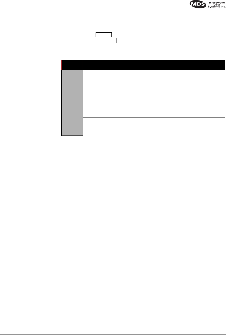
Table 4. LED status indicators
LED Name Description
PWR • Continuous—Power is applied to the radio; no problems detected.
• Flashing 5 times per second—Fault indication.
See Section 8.0, TROUBLESHOOTING (beginning on page
34).
• Flashing once every 4 seconds—radio is in Sleep mode.
SYNC Lights continuously to indicate the radio is receiving/sending
synchronization frames. Normally, within 10 seconds of power-up, this
LED should be lit continuously.
TXD Indicates EIA-232 space (logic high) signal input to the DB-9 connector.
RXD Indicates EIA-232 space (logic high) signal output from the DB-9
connector.

MDS 05-2708A01, Rev. A MDS TransNET I/O Guide 21
Antenna Aiming
For optimum performance of directional antennas, they must be accurately
aimed in the direction of desired transmission. The easiest way to do this is to
point the antenna in the approximate direction, then use the remote radio’s
built-in Received Signal Strength Indication (RSSI) feature to further refine
the heading for maximum received signal strength.
In an MAS system, RSSI readings are only meaningful when initiated from a
remote station. This is because the master station typically receives signals
from several remote sites, and the RSSI would be continually changing as the
master receives from each remote in turn.
Antenna SWR Check
It is necessary to briefly key the transmitter for this check by placing the radio
in the SETUP mode (Page 32) and using the KEY command. (To unkey the
radio, enter DKEY; to disable the setup mode and return the radio to normal
operation, enter Q or QUIT.)
MDS TransNET 900™
Transceiver The SWR of the antenna system should be checked before the radio
is put into regular service. For accurate readings, a wattmeter suited
for 1000 MHz is required. One unit meeting this criteria is the Bird
Model 43™ directional wattmeter with an 5J element installed.
The reflected power should be less than 10% of the forward power
(≈2:1 SWR). Higher readings usually indicate problems with the
antenna, feedline or coaxial connectors.
Data Buffer Setting
The default setting for the data buffer is ON to accommodate virtually any data
format. However, if the system can operate satisfactorily with the buffer OFF,
we recommend doing so using the BUFF OFF command (Page 27). This allows
the radio to operate with the lowest possible latency and improves channel
efficiency.
Hoptime Setting
The default hop time setting is 7. An alternate setting of 28 is used when the
data rate is 115,200 bps.
A detailed explanation of the HOPTIME command, and a table listing the
available selections and the channel efficiency associated with each, can be
found on Page 29.
Baud Rate Setting
The default baud rate setting is 9600 bps to accommodate most systems. If
your system will support a higher data rate, you should increase the radio’s
transmission speed using the BAUD xxxxx abc command (Page 27). It should be
set to the highest speed that can be sent by the data equipment in the system.
(The transceiver supports 1200 to 115200 bps)
Radio Interference Checks
The radio operates in eight frequency zones. If interference is found in one or
more of these zones, the SKIP command (Page 33) can be used to omit them
from the hop pattern. You should also review Section 4.3, A Word About Radio
Interference (beginning on page 10), when dealing with interference problems.

22 MDS TransNET I/O Guide MDS 05-2708A01, Rev. A
7.0 TRANCEIVER PROGRAMMING
There are no manual adjustments on the transceiver. Programming and control
is performed through a PC connected to the Data Interface connector on the
transceiver.
NOTE: The Diagnostic port (RJ-11 connector) uses 8 data bits, 1 stop bit,
and no parity. It can automatically configure itself to function at
1200, 2400, 4800, 9600, 38400, 57600, and 115200 baud.
7.1 Programming Methods
1. Using a Terminal Interface
A PC maybe used without the Radio Configuration software by
operating it in a basic terminal mode (e.g. HyperTerminal session)
and entering the radio commands listed in Table 5. Connect a PC to
the Data Interface connector on the transceiver. Once connected,
communication (baud rate) is established through the command
interface. To access the command interface, an escape character,
followed by one or more ENTER keystrokes (delivered at one second
intervals), until the “>” prompt is displayed. The terminal
communication parameters must be set to 9600 bps, with 8 data bits,
and 1 stop bit (8N1).
2. Using PC Configuration Software
PC-based Radio Configuration software is available for use with the
radio (MDS P/N pending). On-line instructions are included with the
configuration software.
7.2 Keyboard Commands
Table 5 is a reference chart of software commands for the transceiver. See
Section 7.3 for detailed command descriptions.
MDS 05-2708A01, Rev. A MDS TransNET I/O Guide 23
Entering Commands
The proper procedure for entering commands is to type the command,
followed by an keystroke. For programming commands, the
command is followed by and the appropriate information or values,
then .
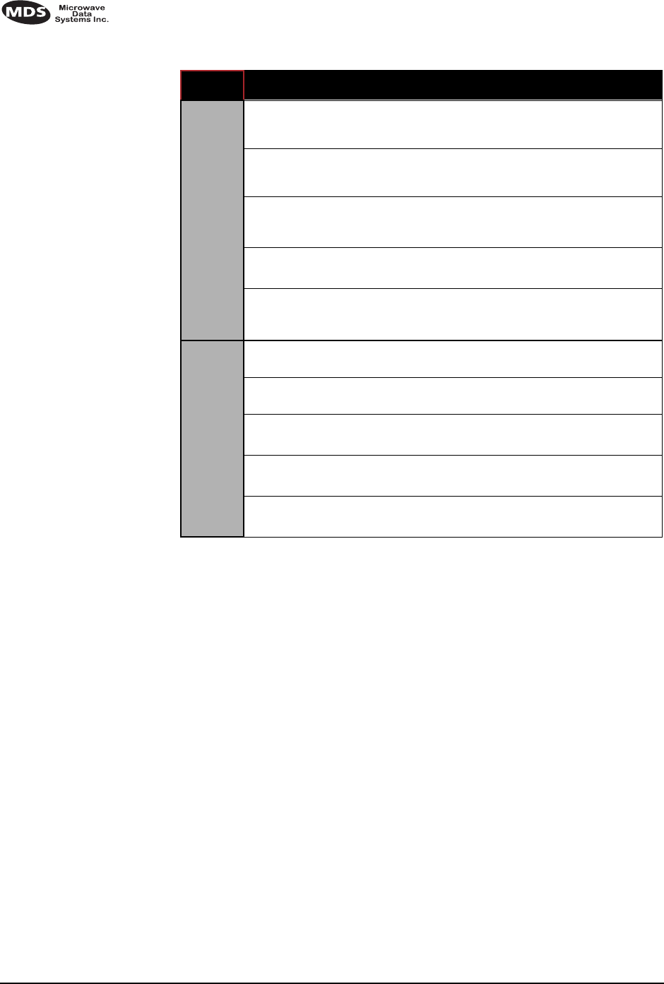
Table 5. Command summary
COMMAND DESCRIPTION
NETWORK
CONFIGURATION
These programming commands
can only be set at the master radio.
BUFF [ON, OFF]
Details Page 27
ON = Seamless data, OFF = Fast byte through-
put.
HOPTIME
Details Page 35
Displays hop time
SEND [n, -n, +n]
Details Page 31
Sets/displays re-send count for data packets.
Useful in areas with heavy radio interference.
SKIP [NONE, 1...8]
Details Page 33
Select combination of frequency operating
zones to avoid.
ENTER
SPACE
ENTER

24 MDS TransNET I/O Guide MDS 05-2708A01, Rev. A
SET/PROGRAM COMMANDS
ADDR [1...65000]
Details Page 26
Program network address
AMASK [0000
0000–FFFF FFFF]
Details Page 27
Sets alarm response. Default is FFFF FFFF.
ASENSE [HI/LO]
Details Page 27
Changes the sense of the alarm output. Default
sense is HI.
BAUD [xxxxx abc]
Details Page 27
Set data communication parameters
CTS [0–255]
Details Page 28
Program CTS delay in milliseconds.
(A value of 0 returns CTS immediately)
CTSHOLD [0-6000]
Details Page 28
Set/display “hold time” that CTS remains
present following last character transmission
from DD-25 port.
DEVICE [DCE, CTS
KEY]
Details Page 28
Set device behavior; DCE (normal) or CTS Key
(Repeater)
MODE [M, R, R-M]
Details Page 30
Program operating mode, where M = Master,
R = Remote, R-M = Remote-Master (Remote
radio programmed to operate on Master fre-
quencies)
OWM [xxxxx]
Details Page 30
Program owner’s message
(30 characters maximum)
OWN [xxxxx]
Details Page 30
Program owner’s name
(30 characters maximum)
PWR [xx–30]
Details Page 30
Program forward power output in dBm.
RTU [ON/OFF/0-80]
Details Page 31
Re-enables or disables the radio’s internal RTU
simulator and sets the RTU address.
RXTOT [NONE,
0–1440]
Details Page 31
Specifies max. duration (in minutes) to wait
before issuing a time-out alarm. Default is OFF.
SEND [n, -n, +n]
Details Page 31
Sets/displays re-send count for data packets.
Useful in areas with heavy radio interference.
UNIT [10000–65000]
Details Page 34
Program unit address. Used to set a unique
address for network-wide diagnostics.
Table 5. Command summary (Continued)
COMMAND DESCRIPTION

MDS 05-2708A01, Rev. A MDS TransNET I/O Guide 25
DISPLAY OPERATING STATUS
ADDR [1...65000]
Details Page 26
Network address (1-65000)
AMASK [0000
0000–FFFF FFFF]
Details Page 27
Sets alarm mask (response). Default is FFFF
FFFF.
ASENSE [HI/LO]
Details Page 27
Changes the sense of the alarm output. Default
sense is HI.
BAUD [xxxxx abc]
Details Page 27
Display data communication parameters.
Example: BAUD 9600 8N1
BUFF [ON, OFF]
Details Page 27
Data buffering mode: ON = seamless data
OFF = fast byte throughput
CTS [0–255]
Details Page 28
CTS delay in ms (0-255 ms)
DEVICE [DCE, CTS
KEY]
Details Page 28
Device behavior (DCE, or CTS KEY)
HOP-
TIME
Details Page 29
Show hop time in milliseconds (ms).
HREV Hardware revision level
MODE [M, R, R-M]
Details Page 30
Show operating mode: M = Master, R =
Remote, R-M = Remote-Master (remote oper.
on master freqs.)
OWM Owner’s message or site name
OWN Owner’s name or system name
PWR [xx–30]
Details Page 30
Forward power output setting in dBm
RSSI
Details Page 30
Received signal strength in dBm (continuously
updated). Not available at master radio unless
SETUP is enabled.
RXTOT [NONE,
0–1440]
Details Page 31
Specifies amount of time (in seconds) to wait
before issuing a time-out alarm. Default is
NONE.
SEND [n, -n, +n]
Details Page 31
Sets/displays re-send count for data packets.
Useful in areas with heavy radio interference.
SER Serial number of radio
SHOW [PORT, DC,
PWR]
Details Page 33
Show active port, DC voltage or measured RF
power (dBm)
SKIP [NONE, 1...8]
Details Page 33
Simplex/half-duplex selection
ON = Simplex, OFF = half-duplex
SKIP [NONE, 1...8]
Details Page 33
Skip a frequency operating zone
Table 5. Command summary (Continued)
COMMAND DESCRIPTION
26 MDS TransNET I/O Guide MDS 05-2708A01, Rev. A
7.3 Detailed Command Descriptions
The essential commands for most applications are Network Address (ADDR),
Mode, (MODE) and Baud Rate (BAUD). However, proper use of the additional
commands allows you to tailor the transceiver for a specific use, or to conduct
basic diagnostics on the radio. This section gives more detailed information for
many of the user commands listed in Table 5.
Most of the commands below can be used in two ways. First, you can type only
the command name (for example, ADDR) to view the currently programmed
data. Second, you can set or change the existing data by typing the command,
followed by a space, and then the desired entry (for example, ADDR 1234). In
the list below, allowable programming variables, if any, are shown in brackets
[ ] following the command name.
ADDR [1...65000]
This command sets or displays the radio’s network address. The network
address can range from 1 to 65000.
Network address must be programmed at the time of installation and must be
common across each radio in a given network. Radios are typically shipped
with the network address unprogrammed. This causes the address to display as
NONE. This leaves the system in an invalid state and prevents operation.
DISPLAY OPERATING STATUS
(CONTINUED)
SSNR
Details Page 33
Signal-to-noise ratio. Expressed in dB.
SREV
Details Page 34
Display transceiver firmware revision level
STAT
Details Page 34
Show current alarm status
TTEMP
Details Page 34
Transceiver’s internal temperature (°C)
UNIT [10000–65000]
Details Page 34
Show programmed unit address for net-
work-wide diagnostics
DIAGNOSTIC/TEST
KEY Enables the transmitter.
(Radio must be in Setup mode.)
DKEY Disables the transmitter.
(Radio must be in Setup mode.)
TX [xxxx]
Details Page 34
Set/display transmit test frequency.
(Radio must be in Setup mode.)
RX [xxxx]
Details Page 31
Set/display receive test frequency.
(Radio must be in Setup mode.)
SETUP
Details Page 32
Enables Setup mode. Times out after 15 min-
utes. Press “Q” to quit.
Table 5. Command summary (Continued)
COMMAND DESCRIPTION

MDS 05-2708A01, Rev. A MDS TransNET I/O Guide 27
NOTE: It is recommended that the last four digits of the master radio’s serial
number be used for the network address (or chassis serial number if
the radio is installed in a P-20 redundant chassis).
ALARM
Table and information pending.
AMASK [0000 0000–FFFF FFFF]
This command sets the alarm bits that cause the alarm output signal to be
triggered. The PWR LED will still flash for all alarms, but the alarm output
signal will only be activated for those alarms that have the corresponding mask
bit set. The hex value for the mask aligns directly with the hex value for the
ALARM command. The default is FFFF FFFF. Through proper use of the AMASK
command, it is possible to tailor the alarm response of the radio. Contact the
factory for more information on configuring the alarm mask.
ASENSE [HI/LO]
This command is used to set or display the sense of the alarm output at Pin 25
of the DATA INTERFACE connector. The default for transceivers is active HI.
BAUD [xxxxx abc]
This command sets or displays the communication attributes for the DATA
INTERFACE port. The command has no effect on the RJ-11 DIAG(NOSTICS)
port.
The first parameter (xxxxx) is baud rate. Baud rate is specified in
bits-per-second and must be one of the following speeds: 1200, 2400, 4800,
9600, 19200, or 38400. In the worst case, the radio will always accept a
minimum of 500 data bytes in a single continuous data transmission. At baud
rates of 4800 bps or less, the radio can support unlimited continuous data
transmission at any hop rate. If hop time is set to NORMAL or LONG, baud rates
of up to 19200 bps with continuous unlimited data transmission are possible.
(See HOPTIME command.)
The second parameter of the BAUD command (abc) is a 3-character block
indicating how the data is encoded. The following is a breakdown of each
character’s meaning:
a = Data bits (7 or 8)
b = Parity (N for None, O for Odd, E for Even)
c = Stop bits (1 or 2)
The factory default setting is 4800 baud, 8 data bits, no parity, 1 stop bit
(Example: 4800 8N1).
NOTE: 7N1, 8O2, and 8E2 are invalid communication settings and are not
supported by the transceiver.
BUFF [ON, OFF]
This command sets or displays the received data handling mode of the radio.
The command parameter is either ON or OFF. (The default is ON.) The setting
of this parameter affects the timing of received data sent out the DATA
INTERFACE connector. Data transmitted over the air by the radio is unaffected
by the BUFF setting.

28 MDS TransNET I/O Guide MDS 05-2708A01, Rev. A
If data buffering is set to OFF, the radio will operate with the lowest possible
average latency. Data bytes are sent out the DATA INTERFACE port as soon as
an incoming RF data frame is disassembled. Average and typical latency will
both be below 10 ms, but idle character gaps may be introduced into the
outgoing data flow.
If data buffering is ON, the radio will operate in a seamless mode. That is, data
bytes will be sent over the air as quickly as possible, but the receiver will buffer
the data until enough bytes have arrived to cover worst case gaps in
transmission. The delay introduced by data buffering may range from 25 to 50
ms, but the radio will not create any gaps in the output data stream. This mode
of operation is required for protocols such as MODBUS™ that do not allow
gaps in their data transmission.
that seamless mode (BUFF ON) is intended only for applications where the
transmitter’s baud rate is greater than or equal to the receiver’s baud rate.
Enforcement of this rule is left up to the user.
Changes to the BUFF setting may only be made at the master radio. This is
because the master radio broadcasts the buffer setting for the entire network.
At remote radios, the buffer setting may be read when the radio is in
synchronization with the master, but it may not be changed.
CLOS
Table and information pending.
CTS [0–255]
The CTS (clear-to-send) command sets or displays the timer value associated
with the CTS line response. The command parameter ranges from 0 to 255
milliseconds.
For DCE operation, the timer specifies how long to wait after the RTS line goes
high before asserting the CTS line. A timer value of zero means that the CTS
line will always be asserted (unless the radio is attempting to throttle back data
as part of normal flow control operation).
For CTS Key operation (see the DEVICE command), the timer specifies how
long to wait after asserting the CTS line before sending data out the DATA
INTERFACE port. A timer value of zero means that data will be sent out the
data port without imposing a key-up delay. (Other delays may be in effect from
other radio operating parameters.)
CTSHOLD [0-6000]
Used in DEVICE CTS KEY mode, this command sets the amount of time in
milliseconds that CTS remains present following transmission of the last
character out the RXD pin of the DATA INTERFACE port. This “hold time” can
be used to prevent squelch tail data corruption when interworking with other
radios.
The CTSHOLD setting can range from 0 to 6000 (i.e., 6 seconds). The default
value is 0, which means that CTS will drop immediately after the last character
is transmitted. If the command is entered when the radio is in DEVICE DCE
mode, the response CTSHOLD N/A will be displayed.
DEVICE [DCE, CTS KEY]
The DEVICE command sets or displays the device behavior of the radio. The
command parameter is either DCE or CTS KEY.

MDS 05-2708A01, Rev. A MDS TransNET I/O Guide 29
The default selection is DCE. In this mode, CTS will go high following RTS,
subject to the CTS programmable delay time. Keying is stimulated by the input
of characters at the data port. Hardware flow control is implemented by
dropping the CTS line if data arrives faster than it can be transmitted.
If CTS KEY is selected, the radio is assumed to be controlling another radio,
such as in a repeater system. The RTS line is ignored and the CTS line is used
as a keyline control for the other radio. CTS is asserted immediately after the
receipt of RF data, but data will not be sent out the DATA INTERFACE port until
after the CTS programmable delay time has expired. (This gives the other radio
time to key.)
Following transmission of the last byte of data, CTS will remain asserted for
the duration specified by the CTSHOLD command. CTSHOLD should be set
sufficiently high.
DMGAP [xx]
The DMGAP command sets the amount of time in milliseconds to wait after the
receipt of a character before interpreting the next received character as the start
of a new message. When data port baud rates are slow, the gap between
characters within a poll may be so long that the radio interprets the next
character as the start of a new poll. When diagnostics is being performed using
passive messaging, this command may be used to change this behavior.
HOPTIME
The HOPTIME command sets or displays the hop time setting. The command is
one of eight keywords whose parameters and related efficiencies are shown in
Table 6.
Although the default setting is 7, transmission efficiency can usually be
improved by using a setting of 28 when data rate exceeds 115200 bps. This is
because there will be less frequent channel hops when using this setting,
contributing to a smoother flow of transmitted data.
Other hop times can be used to customize performance based on SEND count
settings and payload data poll length.
The only time shorter settings (SHORT through XSHORT) should be considered
is when the message size is very small and strong interference of a persistent
nature is occurring on many frequencies. In these cases, a shorter hop time may
improve the chances of a message getting through—but at the cost of reduced
channel efficiency.
Table 6. Hoptime parameters
Hop Time
Keyword
Time
per
Hop
Max.
Bytes
per Hop Channel
Efficiency
XSHORT 10 ms 9 32.1%
16 16 ms 21 46.7%
20 20 ms 30 53.6%
25 25 ms 39 55.7%
32 32 ms 57 63.3%
SHORT 40 ms 72 64.3%
NORMAL 80 ms 162 72.0%
LONG 160 ms 336 74.5%

30 MDS TransNET I/O Guide MDS 05-2708A01, Rev. A
Changes to the HOPTIME setting may only be made at the master radio. (This
is because the master radio establishes the hop time setting for the entire
network.) At remote radios, the hop time setting may be read when the radio is
in synchronization with the master, but it may not be changed.
MODE [M, R, R-M]
The MODE command sets or displays the operating mode of the radio. A master
radio is designated by an M; a remote is designated by an R.
R-M indicates that the transceiver has been programmed to the special
remote-master mode (remote radio operating on master frequencies) This is
used in repeater-assisted peer-to-peer systems; see Section 2.2, Typical
Applications (beginning on page 2) for details. The R-M mode denotes a remote
radio operating on master frequencies. In all other respects, a remote-master
behaves the same as a normal remote.
All units default to remotes; other modes must be specifically programmed
with the MODE command.
OPTION!
Table and information pending.
OWM [xxxxx]
The OWM command sets or displays an optional owner’s message, such as the
system name. The entry can contain up to 30 characters.
OWN [xxxxx]
The OWN command sets or displays an optional owner’s name, such as the site
name. The entry can contain up to 30 characters.
PWR [xx–30]
This command displays or sets the desired RF forward output power setting of
the radio. The PWR command parameter is specified in dBm and can range
from 20 dBm (MDS TransNET 900™ transceiver) through 30 in 1 dBm steps.
The default setting is 30 dBm (1 watt). To read the actual (measured) power
output of the radio, use the SHOW PWR command.
In the USA, maximum allowable power is governed by FCC limits on
Effective Isotropic Radiated Power output (EIRP). The EIRP limit of +36 dBm
means that any user with a net antenna gain greater than 6 dBi must decrease
the PWR setting accordingly. Section 4.5, How Much Output Power Can be
Used? (beginning on page 12) contains a detailed discussion of this topic.
RSSI
This command displays the radio’s Received Signal Strength Indication in
dBm (decibels relative to 1 mW). The output can range from –50 dBm to –110
dBm. Command availability and results depend on the mode of operation
(master or remote). The closer to 0 dBm, the stronger the signal, thus a reading
of –70 dBm is stronger than –80 dBm.

MDS 05-2708A01, Rev. A MDS TransNET I/O Guide 31
For a remote radio, under normal operation, RSSI is based on the average
signal strength of the SYNC message received in each of the eight frequency
zones. (RSSI is sampled each time a SYNC message is received—every 1.6
seconds.) When using the RSSI reading to align a directional antenna, it is
important to make changes slowly so that the RSSI reading will provide
meaningful results. It will take several seconds to indicate a change in signal
level. The radio stays in RSSI mode until is pressed.
For a master radio, under normal operation, entering the RSSI command
causes the response NOT AVAILABLE to be returned. This is because a master is
normally receiving signals from several remote stations and an RSSI reading
would be continually changing. The only exception is when the SETUP
command has been asserted. This disables hopping and allows reading a “raw”
RSSI signal level in real time from a master or remote radio.
NOTE: RSSI Readings are not accurate for incoming signals stronger than
–50 dBm.)
RTU [ON/OFF/0-80]
This command re-enables or disables the radio’s internal RTU simulator,
which runs with MDS’ proprietary polling programs (poll.exe and rsim.exe).
The internal RTU simulator is available whenever a radio has diagnostics
enabled. This command also sets the RTU address that the radio will respond
to.
The internal RTU can be used for testing system payload data or pseudo bit
error rate (BER) testing. It can be helpful in isolating a problem to either the
external RTU or the radio.
RX [xxxx]
This command sets or displays the test receive frequency used in place of
hopping whenever the radio is in Setup mode. The test receive frequency can
be reprogrammed to any value between 927.975 MHz and 902.025 MHz
(MDS TransNET 900™), inclusive. The factory default settings are listed
below and have been selected to be non-intrusive to normal operation.
RXTOT [NONE, 0–1440]
This command sets or displays the amount of time (in minutes) to wait for the
next received data packet before issuing a receiver time-out alarm. The default
is NONE.
SEND [n, -n, +n]
The SEND command selects or displays the number of times that a radio will
re-transmit data. This command is associated with “robust” or “bulletproof”
operation of the radio and is intended for use in areas with heavy radio
interference.
Default Receive Frequencies
Master Remote
MDS
TransNET
900
927.975 MHz 902.025 MHz
ENTER

32 MDS TransNET I/O Guide MDS 05-2708A01, Rev. A
When the SEND command is issued without parameters, the cumulative
retransmission count is shown. A value of 1 represents the default selection,
meaning “normal, non-robust operation.” Values greater than 1 successively
improve the chance of successful data delivery in spectrally harsh
environments. (Note that the SEND count for a remote radio is only viewable
when the remote is synchronized with its master station.)
There are two formats for entering the SEND command. One format (SEND n)
can be used only at the master station, and selects the base transmission count
for the entire network. The other format (SEND +n or –n) can be used at any
radio in the network, and provides a means to customize the transmission count
locally at each radio, as a delta (amount of change) from the base.
For both formats, n represents number between 1 and 10; for the “delta” format
a value of zero is also permitted. The net transmission count for a particular
radio is determined by adding the local “delta” (+n or –n) to the base
transmission count for the network. The net transmission count is
automatically bounded to the range 1..10, irrespective of the delta. The
combination of the two formats provides a means to highly customize the
retransmission behavior of network.
Higher retransmission counts come at the cost of increased latency and
reduced data throughput. With BUFF ON, the radio maintains seamless
operation based on timing derived from the network SEND value. The use of
any tailored SEND values (e.g. SEND +/-x) within the system may disrupt
seamless operation. This is because the increased latency makes seamless
mode impractical. Table 2 lists the maximum cumulative SEND count for
continuous operation, at some typical data rates.
SETUP
This command sets up the transceiver for checking antenna SWR or
transmitter power with external measuring equipment. Do not use this mode
during normal operation.
When the SETUP command is entered, the prompt changes to SETUP>, and:
•Hopping is disabled.
•Synthesizer frequencies are reset to the test frequencies specified by
the TX and RX commands.
•The radio can be keyed using the KEY command. DKEY is used to
unkey the radio. (If the radio is left in a keyed state it is automatically
unkeyed after several minutes.)
•The RSSI is sampled in a raw, continuous fashion regardless of
whether the unit is a master or a remote.
Entering Q or QUIT returns the system to normal operation.
Table 7. Baud Rate vs. Maximum SEND Count
BAUD
RATE
(BPS)
XSHORT
(max. send
count)
16 ms
(max. send
count)
20 ms
(max. send
count)
25 ms
(max. send
count)
32 ms
(max. send
count)
SHORT
(max. send
count)
NORMAL
(max. send
count)
LONG
(max. send
count)
1200 3 8 10 10 10 10 10 10
2400 N/A 4 5 5 5 7 8 8
4800 N/A 2 2 2 2 3 4 4
9600 N/A N/A N/A N/A N/A N/A 2 2

MDS 05-2708A01, Rev. A MDS TransNET I/O Guide 33
A timer keeps the Setup mode from accidentally leaving the system disabled.
After 10 minutes the system behaves as if Q or QUIT had been entered,
returning to normal operation.
SHOW [PORT, DC, PWR]
The SHOW command displays three types of information based on the
command variables. These are:
•PORT—Displays which connector port (RJ-11 or DB-9) is currently
active for diagnostics and control.
•DC—Displays DC input/output voltages.
•PWR—Displays the actual (measured) RF power output in dBm.
Unlike the PWR command, this command shows the actual level
being measured, not the programmed RF power setting.
SKIP [NONE, 1...8]
This command sets or displays which, if any, of the eight 3.2 MHz TransNET
900 (128 frequency) zones will be skipped from the radio’s hopping
sequence. Skipping zones is one way of dealing with constant interference on
one or more frequencies. See Section 4.3 (Page 10) for more information on
dealing with interference.
Figure 18 shows the frequency range covered by each zone. The command
parameter is either the keyword NONE or an undelimited string of up to seven
digits where each digit 1...8 represents a corresponding zone to skip. (For zone
parameter input, the digits can appear in any order and can be optionally
separated by a blank space.) The SKIP command is read-only at remote radios.
(Remotes must be synchronized with the master radio to read the skip status.)
Invisible place holder
Figure 18. Frequency zones for MDS TransNET 900 transceivers
SSNR
This command displays the signal-to-noise ratio of the received signal
expressed in dB. As used in this guide, the definition of signal-to-noise is based
upon the signal level following equalization, for valid frames only. (A valid
frame is defined as containing no more than one bit error, and belonging to a
frame addressed for the receiving radio.) SNR is updated and latched for each
valid frame received. A filter in the DSP tempers the effect of any sudden
changes in the value.
SNR output ranges from 10 dB to 33 dB. A value of 10 dB represents little or
no signal. A value of 24 dB represents a very strong signal. For remote radios,
a value of 0 is reserved to mean “no signal”; it is displayed whenever a remote
is not in synchronization with the master station.
When the SNR command is used, it causes the DIAG(NOSTIC) port to enter an
update mode, and it will provide an updated signal-to-noise ratio every 1.6
seconds. It stays in this mode until the key is pressed.
ZONE 1
902.200
to
905.375
ZONE 2
905.400
to
908.575
ZONE 3
908.600
to
911.775
ZONE 4
911.800
to
914.975
ZONE 5
915.000
to
918.175
ZONE 6
918.200
to
921.375
ZONE 7
921.400
to
924.575
ZONE 8
924.600
to
927.775
MDS TransNET 900 TRANSCEIVER
ENTER

34 MDS TransNET I/O Guide MDS 05-2708A01, Rev. A
SREV
This command displays the software version currently loaded into the
transceiver.
A display of 06-3111A01, 3.5.1 is an example of the software version identifier.
STAT
This command is used to check alarm status.
If an alarm does exist, a two-digit event code (00–31) is displayed and the
event is identified as a “major” or “minor” alarm. A brief description of the
event is also given.
If more than one alarm exists, the word MORE appears at the bottom of the
screen and additional alarms are viewed by pressing the key. Detailed
descriptions of the alarm codes are provided in Table 9 on page 36.
TTEMP
This command displays the internal temperature of the transceiver in degrees
Celsius. (Note that the radio is specified to operate in an environment between
–30 C° and +60 C°). This internal reading may be higher than the outside
temperature by several degrees.
TX [xxxx]
This command sets or displays the test transmit frequency used in place of
hopping whenever the radio is in Setup mode. The test transmit frequency can
be reprogrammed to any value between 902.025 MHz and 927.975 MHz
TransNET 900, inclusive. The factory default settings are listed below and
have been selected to be non-intrusive to normal system operation.
UNIT [10000–65000]
This command sets the unit addressing for network-wide diagnostics. The unit
address is factory programmed to the last four digits of the serial number. If
re-programmed in the field, the entry must consist of five digits between 10000
and 65000.
8.0 TROUBLESHOOTING
Successful troubleshooting of an MDS transceiver system is not difficult, but
requires a logical approach. It is best to begin troubleshooting at the master
station, as the rest of the system depends on the master for polling instructions
and synchronization data. If the master station has problems, the operation of
the entire network will be affected.
When communication problems are found, it is good practice to begin by
checking the simple things. All radios in the network must meet these basic
requirements:
Default Transmit Frequencies
Master Remote
MDS TransNET
900
927.975 MHz
2400.08 MHz
902.025 MHz
2483.44 MHz
ENTER

MDS 05-2708A01, Rev. A MDS TransNET I/O Guide 35
•Adequate and stable primary power
•An efficient and properly aligned antenna system
•Secure connections (RF, data & power)
•Proper programming of the radio’s operating parameters, especially
Mode selection (MODE), Network Address (ADDR), and interface
Baud Rate (BAUD)
•The correct interface between the radio and the connected data
equipment (proper cable wiring, data format and timing).
8.1 LED Indicators
The LED status indicators are an important troubleshooting tool and should be
checked whenever a problem is suspected. Table 8 describes the function of
each status LED.
8.2 Alarm Codes
When an alarm condition exists, the transceiver creates an alarm code. These
codes can be very helpful in resolving many system difficulties.
Checking for Alarms—STAT command
To check for the presence of alarms, enter STAT. If no alarms exist, the message
NO ALARMS PRESENT appears at the top of the display.
If an alarm does exist, a two-digit alarm code (00–31) is displayed, and it is
identified as a major or minor alarm. A brief description of the alarm is also
given. Alarm codes and their meanings are listed in Table 9.
If more than one alarm exists, the word MORE appears at the bottom of the
screen; additional alarms can be viewed by pressing .
Major Alarms vs. Minor Alarms
Major alarms report serious conditions that generally indicate a hardware
failure, or other abnormal condition that will prevent (or seriously hamper)
further operation of the transceiver.
PWR SYNC TXD RXD
Table 8. LED status indicators
LED Name Description
PWR • Continuous—Power is applied to the radio, no problems detected.
• Flashing 5 times per second—Fault indication.
See Section 8.0, TROUBLESHOOTING (beginning on page
34).
• Flashing once every 4 seconds—Radio is in Sleep Mode.
SYNC Lights continuously to indicate the radio is receiving/sending
synchronization frames. Within 16 seconds of start-up, this LED should
be lit continuously.
TXD Indicates EIA-232 space signal (logic high) input to the DB-9 connector.
RXD Indicates EIA-232 space signal (logic high) output from the DB-9
connector.
ENTER

36 MDS TransNET I/O Guide MDS 05-2708A01, Rev. A
With the exception of alarm code 00 (network address not programmed), major
alarms generally indicate the need for factory repair. Contact MDS for further
assistance.
Minor alarms report conditions which, under most circumstances, will not
prevent transceiver operation. This includes out-of-tolerance conditions, baud
rate mismatches, etc. The cause of these alarms should be investigated and
corrected to prevent system failure.
Alarm Code Definitions
Table 9 contains a listing of all event codes that may be reported by the
transceiver.
Table 9. Alarm codes
Alarm
Code Alarm
Type Description
00 Major The network address is not programmed.
01 Major Improper software detected for this radio model.
02, 03 -- Reserved for factory use.
04 Major One or more of the programmable synthesizer loops is reporting
an out-of-lock condition.
05 -- Reserved for factory use.
08 Major The system is reporting that it has not been calibrated. Factory
calibration is required for proper radio operation.
09 -- Reserved for factory use.
10 Major The microcontroller unit (MCU) was unable to properly program
the system to the appropriate defaults. A hardware problem may
exist.
11 -- Reserved for factory use.
12 Major Receiver time-out alarm.
13-15 -- Reserved for factory use.
16 Minor The unit address is not programmed.
17 Minor A data parity fault has been detected on the DATA INTERFACE
connector. This usually indicates a parity setting mismatch
between the radio and the RTU.
18 Minor A data framing error has been detected on the DATA
INTERFACE connector. This may indicate a baud rate
mismatch between the radio and the RTU.
19–24 -- Reserved for factory use.
27, 28 -- Reserved for factory use.
29 Minor RF output power fault detected. (Power differs by more than 2
dB from set level.) Often caused by high antenna system SWR.
Check antenna, feedline and connectors.
30 Minor The system is reporting an RSSI reading below –105 dBm. Bit
errors are likely to be present in the data.
31 Minor The transceiver’s internal temperature is approaching an
out-of-tolerance condition. If the temperature drifts outside of the
recommended operating range, system operation may fail.

MDS 05-2708A01, Rev. A MDS TransNET I/O Guide 37
8.3 Troubleshooting Chart
Table 10 provides suggestions for resolving system difficulties that may be
experienced in the radio system. If problems persist, contact the factory for
further assistance. Refer to the inside back cover of this guide for contact
information.
9.0 TECHNICAL REFERENCE
The following section contains material that is not essential to using the radio,
but may prove helpful in diagnosing performance problems or in gaining a
better understanding of the unit’s operation.
9.1 Technical Specifications
GENERAL
Frequency Hopping Range: Up to 1028 frequencies within:
MDS TransNET 900™: 902–928 MHz,
configurable in 3.2 MHz zones
Hop Pattern: Based on network address
Frequency Stability: ±1.5 ppm
Simplex Operation: User selectable
Half-Duplex Operation: MDS TransNET 900™: ±1.6 MHz TX/RX split
Network Addresses: 65,000
Temperature Range: –30°C to +60°C
Humidity: <95% at +40°C; non-condensing
Table 10. Troubleshooting chart
Difficulty Recommended System Checks
Unit is
inoperative. a. Check for the proper supply voltage at the power connector.
b. The transceiver’s internal resettable fuse may have tripped. To
reset it, momentarily remove and re-apply power to the radio.
Interference is
suspected. a. Verify that the system has a unique network address. Nearby
systems with the same address will cause interference.
b. Check for interference by locking out affected zone(s) using the
SKIP command (Page 33).
c. If omnidirectional antennas are used on remote stations, consider
changing to directional antennas. This will often limit interference
to and from other stations.
No
synchronization
with master, or
poor overall
performance.
a. Check for secure interface connections at the radio and the
connected device.
b. Check the antenna, feedline and connectors. Reflected power
should be less than 10% of the forward power reading
(SWR ≈2:1 or lower).
c. If the remote radio is in synchronization, but performance is poor,
check the received signal strength using the RSSI command
(Page 30). If RSSI is low, it may indicate antenna problems, or
misalignment of directional antenna headings.
d. Verify proper programming of system parameters: mode, network
address, data interface baud rate, transmitter power, CTS delay,
etc.
e. Check for alarms using the STAT command (Page 34)

38 MDS TransNET I/O Guide MDS 05-2708A01, Rev. A
Primary Power: 13.8 Vdc (10.5–30 Vdc range)*
* Units shipped prior to the year 2000 may be
configured for 25 Vdc maximum DC input.
Supply Current (typical):
Transmit: MDS TransNET 900™: 400 mA @ 13.8 Vdc
Receive: MDS TransNET 900™: 125 mA @ 13.8 Vdc
Sleep Mode: <5 mA @ 13.8 Vdc
Size (excluding mtg. hardware):
Enclosed Version: 5.30" x 3.50” x 1.40"
135 x 89 x 36 mm
: Board Version: 4.00"W x 3.25 ” x 0.50"
: 102 x 83 x 13 mm
Case: Die-cast aluminum
Pending Approvals: • FCC Part 15.247
• Industry Canada RSS-210 and RSS-139
• ETSI ETS 300 328
• UL/FM Class 1, Div. 2; Groups A, B, C and D
hazardous locations
• UL Listed
• CE Mark
• Contact MDS for information on availability and
governmental approvals in other countries
DATA CHARACTERISTICS
Data Interface: TTL/RS-232/RS-485
Interface Connector: DB-9 female
Data Rate: 1200, 2400, 4800, 9600, 19200, 38400, 57600,
115200 bps asynchronous
Data Latency: <5 ms typical (buffer off)
Byte Length: 10 or 11 bits
Maximum Data Transmission: Continuous up to 115200 bps
RF CHARACTERISTICS
TRANSMITTER:
Power Output
(at antenna connector): MDS TransNET 900™: 0.1 to 1.0 watt (+20 dBm to
+30 dBm) ±1.0 dB, set by user
Duty Cycle: Continuous
Modulation Type: Binary CPFSK
Output Impedance: 50 Ohms
Spurious: –60 dBc
Harmonics: –80 dBc
RECEIVER
Type: Double conversion superheterodyne
Bit-Error Rate: MDS TransNET 900™: Less than 1x10⁻⁶ at –105
dBm
Intermodulation: MDS TransNET 900™: 59 dB minimum (EIA)
Desensitization: MDS TransNET 900™: 75 dB
Spurious: 70 dB minimum
Bandwidth: MDS TransNET 900™: 200 KHz
Interference Ratio
(BER degraded by 10-1): Co-channel:–10 dB
Adjacent channel:+30 dB
Two channels away:+50 dB
Three channels away:+60 dB
Time Required to Synchronize
with Master Radio: Less than 10 seconds (typical)

MDS 05-2708A01, Rev. A MDS TransNET I/O Guide 39
9.2 Data Interface Connections (DB-9)
The DATA INTERFACE connector is used to connect the radio to an external
DTE data terminal that supports the EIA-232 format. The radio supports data
rates of 1200, 2400, 4800, 9600, 19200, 38400, 57600, and 115200 bps
(asynchronous data only).
The DATA INTERFACE connector mates with a standard DB-9 plug that is
available from many electronics parts distributors. Figure 19 shows the layout
of the DATA INTERFACE connector.Table 11 lists each pin on the connector
and describes its function.
Invisible place holder
Figure 19. Data interface connector (DB-9) pins
As viewed from outside the radio
Table 11. Data interface connector (DB-9) pin descriptions
Pin
Number Input/
Output Pin Description
1 OUT DCD—Data Carrier Detect
A “high” indicates hopping synchronization.
2 OUT RXD—Received Data
Supplies received data to the connected device.
3 IN TXD—Transmitted Data
Accepts TX data from the connected device.
4 IN Sleep Mode
A ground on this pin turns off most circuits in the radio,
including transmit, receive, modem, and diagnostic
functions. This allows for greatly reduced power
consumption, yet preserves the radio’s ability to be quickly
brought on line. See Section 5.6, Using the Radio’s Sleep
Mode (beginning on page 31) for details.
5 IN Protective Ground
Connects to ground (negative supply potential) on the
radio’s PC board and chassis.

40 MDS TransNET I/O Guide MDS 05-2708A01, Rev. A
9.3 dBm-Watts-Volts Conversion Chart
Table 12 is provided as a convenience for determining the equivalent voltage
or wattage of an RF power expressed in dBm.
6 OUT Alarm Output
A logic low (less than 0.5 volts) on this in indicates normal
operation. A logic high (greater than 4 volts) indicates that
an alarm condition is present. This pin can be used as an
alarm output, provided the internal series resistance of 1
kW is considered.
DSR—Data Set Ready
Provides a +6 Vdc DSR signal through a 2.5 kΩ resistor.
7IN
--
RTS—Request-to-Send Input
Signal Ground
Connects to ground (negative supply potential) at the
radio’s PC board.
8 OUT CTS—Clear-to-Send Output
Goes “high” after the programmed CTS delay time has
elapsed (DCE), or keys an attached radio when RF data
arrives (CTS KEY).
DCD—Data Carrier Detect
A “high” indicates hopping synchronization.
9 -- Unused.
Table 11. Data interface connector (DB-9) pin descriptions(Continued)
Pin
Number Input/
Output Pin Description

MDS 05-2708A01, Rev. A MDS TransNET I/O Guide 41
Table 12. dBm-Watts-Volts conversion—for 50 ohm systems
dBm V Po
+53 100.0 200W
+50 70.7 100W
+49 64.0 80W
+48 58.0 64W
+47 50.0 50W
+46 44.5 40W
+45 40.0 32W
+44 32.5 25W
+43 32.0 20W
+42 28.0 16W
+41 26.2 12.5W
+40 22.5 10W
+39 20.0 8W
+38 18.0 6.4W
+37 16.0 5W
+36 14.1 4W
+35 12.5 3.2W
+34 11.5 2.5W
+33 10.0 2W
+32 9.0 1.6W
+31 8.0 1.25W
+30 7.10 1.0W
+29 6.40 800mW
+28 5.80 640mW
+27 5.00 500mW
+26 4.45 400mW
+25 4.00 320mW
+24 3.55 250mW
+23 3.20 200mW
+22 2.80 160mW
+21 2.52 125mW
+20 2.25 100mW
+19 2.00 80mW
+18 1.80 64mW
+17 1.60 50mW
+16 1.41 40mW
+15 1.25 32mW
+14 1.15 25mW
+13 1.00 20mW
+12 .90 16mW
+11 .80 12.5mW
+10 .71 10mW
+9 .64 8mW
+8 .58 6.4mW
+7 .500 5mW
+6 .445 4mW
+5 .400 3.2mW
+4 .355 2.5mW
+3 .320 2.0mW
+2 .280 1.6mW
+1 .252 1.25mW
dBm V Po
0 .225 1.0mW
-1 .200 .80mW
-2 .180 .64mW
-3 .160 .50mW
-4 .141 .40mW
-5 .125 .32mW
-6 .115 .25mW
-7 .100 .20mW
-8 .090 .16mW
-9 .080 .125mW
-10 .071 .10mW
-11 .064
-12 .058
-13 .050
-14 .045
-15 .040
-16 .0355
dBm mV Po
-17 31.5
-18 28.5
-19 25.1
-20 22.5 .01mW
-21 20.0
-22 17.9
-23 15.9
-24 14.1
-25 12.8
-26 11.5
-27 10.0
-28 8.9
-29 8.0
-30 7.1 .001mW
-31 6.25
-32 5.8
-33 5.0
-34 4.5
-35 4.0
-36 3.5
-37 3.2
-38 2.85
-39 2.5
-40 2.25 .1µW
-41 2.0
-42 1.8
-43 1.6
-44 1.4
-45 1.25
-46 1.18
-47 1.00
-48 0.90
dBm mV Po
-49 0.80
-50 0.71 .01µW
-51 0.64
-52 0.57
-53 0.50
-54 0.45
-55 0.40
-56 0.351
-57 0.32
-58 0.286
-59 0.251
-60 0.225 .001µW
-61 0.200
-62 0.180
-63 0.160
-64 0.141
dBm µV Po
-65 128
-66 115
-67 100
-68 90
-69 80
-70 71 .1nW
-71 65
-72 58
-73 50
-74 45
-75 40
-76 35
-77 32
-78 29
-79 25
-80 22.5 .01nW
-81 20.0
-82 18.0
-83 16.0
-84 11.1
-85 12.9
-86 11.5
-87 10.0
-88 9.0
-89 8.0
-90 7.1 .001nW
-91 6.1
-92 5.75
-93 5.0
-94 4.5
-95 4.0
-96 3.51
-97 3.2
dBm µV Po
-98 2.9
-99 2.51
-100 2.25 .1pW
-101 2.0
-102 1.8
-103 1.6
-104 1.41
-105 1.27
-106 1.18
dBm nV Po
-107 1000
-108 900
-109 800
-110 710 .01pW
-111 640
-112 580
-113 500
-114 450
-115 400
-116 355
-117 325
-118 285
-119 251
-120 225 .001pW
-121 200
-122 180
-123 160
-124 141
-125 128
-126 117
-127 100
-128 90
-129 80 .1ƒW
-130 71
-131 61
-132 58
-133 50
-134 45
-135 40
-136 35
-137 33
-138 29
-139 25
-140 23 .01ƒW

42 MDS TransNET I/O Guide MDS 05-2708A01, Rev. A
NOTES
A
Accessories (table) 14
ADDR command (set/display radio network address) 38
Alarm
checking for 50
code definitions 50
codes 50
codes, table 50
major vs. minor 50
receiver timeout (RXTOT command) 45
reset output signal 39
set/display output sense (ASENSE command) 39
status (STAT command) 48
ALARM command (obsolete; see STAT command) 48
AMASK command (configure alarm output signal) 39
Antenna
installation 26
performance optimization 32
selection 21
SWR check 32
system gain vs. power output setting, table 23
system gain, defined 14
Yagi, illustrated 22
ASENSE command (set/display alarm output sense) 39
B
BAUD command (set/display data interface port attributes) 39
Baud rate
setting 33
Bit, defined 14
BPS (bits-per-seond), defined 14
BUFF command (set/display received data handling mode) 40
Byte, defined 14
C
Cable
data equipment to DATA INTERFACE connector 26, 34
data interface wiring for null-modem 29
data interface wiring for tail-end links 28
feedlines 22
maximum length, recommended 26
null-modem, for repeater system 28, 29
power (positive/negative leads) 27
Commands
ADDR (set/display radio network address) 38
AMASK (configure alarm output signal) 39
ASENSE (set/display alarm output sense) 39
BAUD (set/display data interface port attributes) 39
BUFF (set/display received data handling mode) 40
CTS (set/display CTS line response timer) 40
CTSHOLD (set/display CTS hold timer) 41
detailed descriptions 35—??
DEVICE (set/display DCE or CTS Key behavior) 41
display operating status 37
DMGAP (set time to wait between characters) 42
DTYPE (set radio s diagnopstics type) 42
entering on Hand-Held Terminal (HHT) 35
Hand-Held Terminal (HHT) 34
HOPTIME (set/display hoptime setting) 42
how used 38
MODE (set/display master/remote operation) 43
most used 35, 38
network configuration 35
OWM (set/display optional owner s message) 43
OWN (set/display optional owner s name) 43
PWR (set/display RF forward output power) 43
RSSI (display received signal strength) 43
RTU (enable/disable internal RTU) 44
RX (set/display test receive frequency) 44
RXTOT (set/display received data timeout value) 45
SEND (set/display number of re-sends) 45
set/program 36
SETUP (enter testing and setup mode) 46
SHOW (display active port, dc volts, measured power output) 47
SIMPLEX (set/display simplex/half-duplex operation) 47
SKIP (set/display frequency zone to skip) 47
SKIPSYNC (set/display status of SYNC messages in skipped zones) 47
SNR (display signal-to-noise ratio) 47
SREV (display transceiver software version) 48
STAT (list alarms) 48
summary, table 35
TDD (set/display time division multiplex status) 48
TEMP (display internal temperature) 48
CTS command (set/display CTS line response timer) 40
CTSHOLD command (set/display CTS hold timer) 41
D
Data buffer setting 33, 40
DATA INTERFACE
connections 54
connector pin descriptions, table 55
connector pins, illustrated 55
Data interface
cable wiring for repeater, illustrated 29
cable wiring for tail-end links, illustrated 28
dBi, defined 14
dBm, defined 15
DCE, defined 15
Decibel (dB), defined 14
Default settings
data interface baud rate 33
DEVICE command (set/display DCE or CTS Key behavior) 41
Diagnostics
setup mode (SETUP command) 46
Display
alarm output sense (ASENSE command) 39
alarms (STAT command) 48
connector port, diagnostics (SHOW command) 47
CTS hold timer value (CTSHOLD command) 41
CTS line response timer value (CTS command) 40
data interface baud rate (BAUD command) 39
dc input/output voltages (SHOW command) 47
device behavior (DEVICE command) 41
hoptime setting (HOPTIME command) 42
master or remote operation (MODE command) 43
network address (ADDR command) 38
operating status commands 37
owner s message (OWM command) 43
owner s name (OWN command) 43
received data handling mode (BUFF command) 40
received data timeout value (RXTOT command) 45
received signal strength (RSSI command) 43
RF forward output power (PWR command) 43
RF power output, actual measured (SHOW command) 47
signal-to-noise ratio (SNR command) 47
simplex or half-duplex operation (SIMPLEX command) 47
skipped frequency zones (SKIP command) 47
software version, transceiver (SREV command) 48
temperature, internal (TEMP command) 48
test receive frequency (RX command) 44
DKEY command (dekey transmitter) 32, 38, 46
DMGAP command (set/display time to wait between characters) 42
DSP (Digital Signal Processing), defined 15
DTE, defined 15
DTYPE command (set radio s diagnostics type) 42
E
EEPROM FAILURE error message 35
Enable
internal RTU (RTU command) 44
master/remote operation (MODE command) 43
Setup mode (SETUP command) 46
simplex/half-duplex operation (SIMPLEX command) 47
skipped zone (SKIP command) 47
Sleep Mode 30
Equalization, defined 15
Error messages
on Hand-Held Terminal (HHT) 35
F
Fade margin, defined 15
Feedline
selection 21, 22
Frame, defined 15
Frequency hopping, defined 15
Frequency zone
defined 15
table 47
G
Gate (radio diagnostics type) 42
Glossary 14—17
H
Hand-Held Terminal (HHT)
command summary, table 35
entering commands 35
error messages 35
keyboard commands 34
Hardware flow control, defined 15
Hopping, defined 15
Hoptime
parameters, table 42
setting 33
HOPTIME command (set/display hoptime setting) 42
Host computer, defined 15
I
Illustrations
antenna, Yagi 22
data interface cable wiring for repeater 29
data interface cable wiring for tail-end links 28
DATA INTERFACE connector pins 55
LED status indicators 32
model configuration code 10
point-to-point link 12
remote station arrangement 18
repeater system configuration 13
simplex peer-to-peer network 12
tail-end link 13
transceiver 9
typical MAS network 11
Installation 24—31
antenna 26
connecting transceiver to data equipment 26, 34
feedline selection 22
peer-to-peer systems 27
performance optimization 32
primary power 27
repeaters 28
requirements 17
site selection 18
site survey 19
tail-end links 27
transmission path 18
Interference
about 20
checks 33
troubleshooting 52
K
Key
set to CTS keying (DEVICE command) 41
transmitter, for antenna SWR check 32
KEY command (key transmitter) 32, 38, 46
L
Latency, defined 16
LED status indicators
illustrated 32
table 32
M
Master Station
defined 16
MCU (Microcontroller Unit), defined 16
MODE command (set/display master/remote operation) 43
Mode, defined 16
Model configuration code, illustrated 10
Mounting instructions 25
Multiple Address System (MAS)
defined 16
network, illustrated 11
N
Network address
defined 16
Network configuration commands 35
Network-wide diagnostics
defined 16
Node (radio diagnostics type) 42
O
Operation 31—33
OWM command (set/display optional owner s message) 43
OWN command (set/display optional owner s name) 43
P
Peer (radio diagnostics type) 42
Peer-to-peer network
installation 27
Performance optimization 32
Pins, DATA INTERFACE connector descriptions (table) 55
PLC (Programmable Logic Controller), defined 16
Point-to-multipoint system
defined 16
power usage 23
Point-to-point system
link, illustrated 12
Poll, defined 16
Power
how much can be run 23
measuring and installing primary 27
set/display RF forward output (PWR command)Set
RF forward output power (PWR command) 43
sleep mode 30
Procedures
antenna aiming 32
antenna and feedline selection 21
antenna SWR check 32
connecting data equipment to DATA INTERFACE connector 26, 34
enabling sleep mode 30
entering commands using Hand-Held Terminal (HHT) 35
installation 24—31
installation planning 17
installing the antenna and feedline 26
interference check 33
measuring and installing primary power 27
mounting the transceiver 25
performance optimization 32
programming the radio 33—35, ??—35
reading LED status indicators 31
site selection 18
troubleshooting 49—52
Programming radio 33—??
PWR command (set/display RF forward output power) 43
R
Radio
inoperative (troubleshooting chart) 52
no synchronization with master (troubleshooting chart) 52
poor performance (troubleshooting chart) 52
Remote radio
defined 16
Remote station
typical arrangement, illustrated 18
Repeater
data interface cable wiring for, illustrated 29
installation 28
system, illustrated 13
Root (radio diagnostics type) 42
RSSI command (display received signal strength) 43
RTU (Remote Terminal Unit)
defined 17
RTU command (enable/disable internal RTU) 44
RX command (set/display test receive frequency) 44
RXTOT command (set/display received data timeout value) 45
S
SCADA (Supervisory Control and Data Acquisition), defined 17
SEND command (set/display number of re-sends) 45
Set
alarm output sense (ASENSE command) 39
alarm output signal (AMASK command) 39
CTS hold timer (CTSHOLD command) 41
CTS line response timer (CTS command) 40
data interface baud rate (BAUD command) 39
DCE or CTS Key device behavior (DEVICE command) 41
frequency zone to skip (SKIP command) 47
hoptime (HOPTIME command) 42
master/remote operation (MODE command) 43
network address (ADDR command) 38
owner s message (OWM command) 43
owner s name (OWN command) 43
received data handling mode (BUFF command) 40
received data timeout value (RXTOT command) 45
simplex or half-duplex operation (SIMPLEX command) 47
test receive frequency (RX command) 44
testing mode (SETUP command) 46
Set/program commands 36
SETUP command (enter testing and setup mode) 46
SHOW command (display active port, dc volts, measured power output) 47
Simplex
installing peer-to-peer system 27
peer-to-peer network, illustrated 12
SIMPLEX command (set/display simplex/half-duplex operation) 47
Site selection 18
SKIP command (set/display frequency zone to skip) 47
SKIPSYNC (set/display status of SYNC messages in skipped zones) 47
Sleep mode 30
SNR command (display signal-to-noise ratio) 47
SREV command (display transceiver software version) 48
STAT command (list alarms) 48
SWR (Standing Wave Ratio)
defined 17
performance optimization 32
T
Tables
accessories 14
alarm codes 50
antenna system gain vs. power output setting 23
DATA INTERFACE connector pin descriptions 55
frequency zones 47
Hand-Held Terminal (HHT) command summary 35
hop time parameters 42
LED status indicators 32
troubleshooting 52
Tail-end link
cable wiring for, illustrated 28
illustrated 13
installation 27
TDD (set/display time division multiplex status) 48
Technical reference 52—57
Technical specifications 52—54
TEMP command (display internal temperature) 48
Temperature, display internal (TEMP command) 48
Transceiver
connecting to data equipment 26, 34
illustrated 9
mounting instructions 25
performance optimization 32
sleep mode 30
Troubleshooting 49—52
table 52

IN CASE OF DIFFICULTY...
MDS products are designed for long life and trouble-free operation. However, this equipment, as
with all electronic equipment, may have an occasional component failure. The following informa-
tion will assist you in the event that servicing becomes necessary.
FACTORY TECHNICAL ASSISTANCE
Technical assistance for MDS products is available from our Customer Support Team during busi-
ness hours (8:00 A.M.—5:30 P.M. Eastern Time). When calling, please give the complete model
number of the radio, along with a description of the trouble symptom(s) that you are experiencing.
In many cases, problems can be resolved over the telephone, without the need for returning the unit
to the factory.
Please use the following telephone numbers for product assistance:
716-242-9600 (Phone)
716-242-9620 (FAX)
FACTORY REPAIRS
Component level repair of radio equipment is not recommended in the field. Many components are
installed using surface mount technology, which requires specialized training and equipment for
proper servicing. For this reason, the equipment should be returned to the factory for any PC board
repairs. The factory is best equipped to diagnose, repair and align your radio to its proper operating
specifications.
If return of the equipment is necessary, you will be issued a Returned Material Authorization
(RMA) number. The RMA number will help expedite the repair so that the equipment can be
repaired and returned to you as quickly as possible. Please be sure to include the RMA number on
the outside of the shipping box, and on any correspondence relating to the repair. No equipment
will be accepted for repair without an RMA number.
A statement should accompany the radio describing, in detail, the trouble symptom(s), and a
description of any associated equipment normally connected to the radio. It is also important to
include the name and telephone number of a person in your organization who can be contacted if
additional information is required.
The radio must be properly packed for return to the factory. The original shipping container and
packaging materials should be used whenever possible. All factory returns should be addressed to:
When repairs have been completed, the equipment will be returned to you by the same shipping
method used to send it to the factory. Please specify if you wish to make different shipping arrange-
ments.
Microwave Data Systems
Customer Service Department
(RMA No. XXXX)
175 Science Parkway
Rochester, NY 14620 USA
175 Science Parkway, Rochester, New York 14620
General Business: +1 (716) 242-9600
FAX: +1 (716) 242-9620
World Wide Web: http://www.mdsroc.com
175 Science Parkway, Rochester, New York 14620
General Business: +1 (716) 242-9600
FAX: +1 (716) 242-9620
World Wide Web: http://www.mdsroc.com