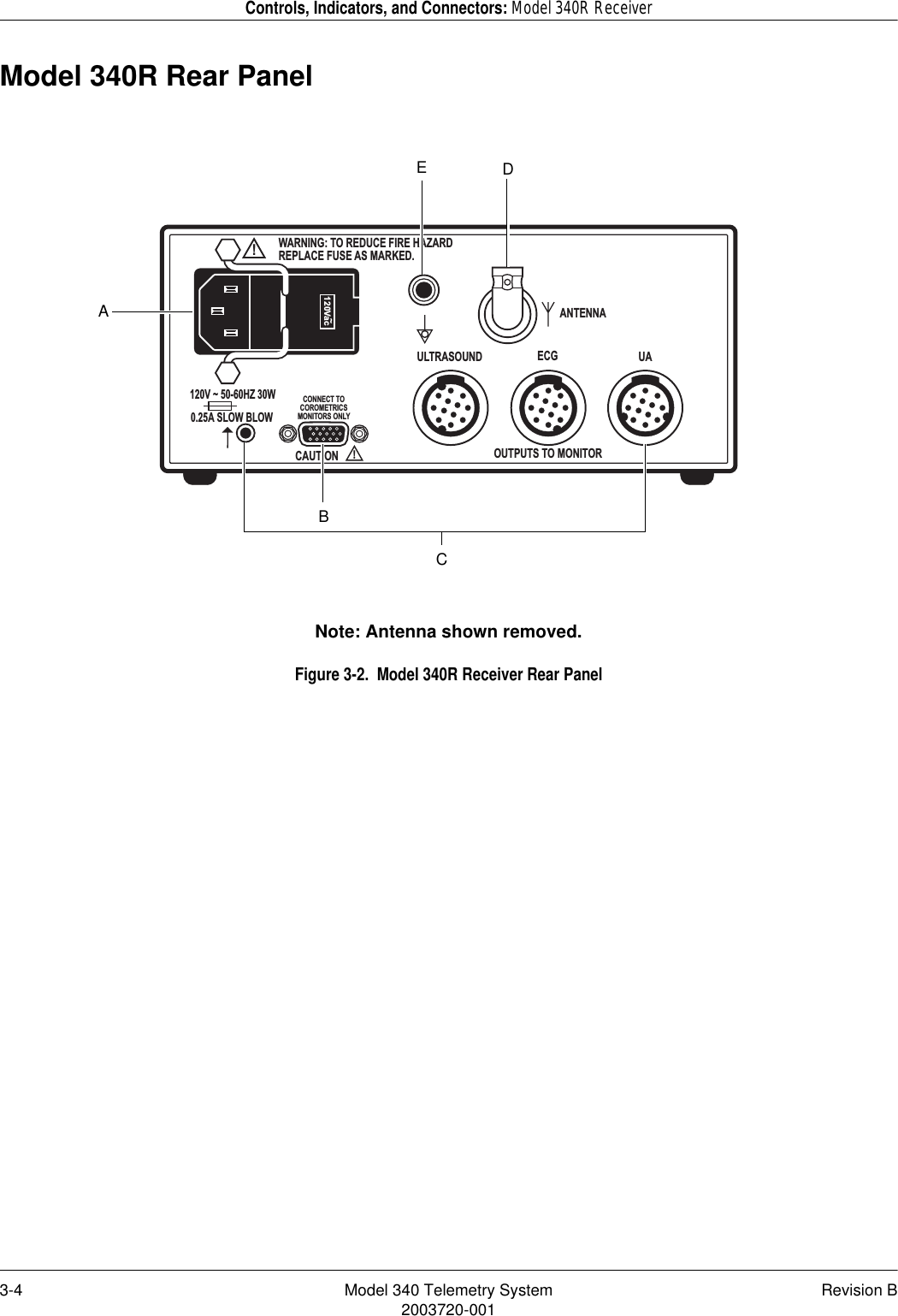
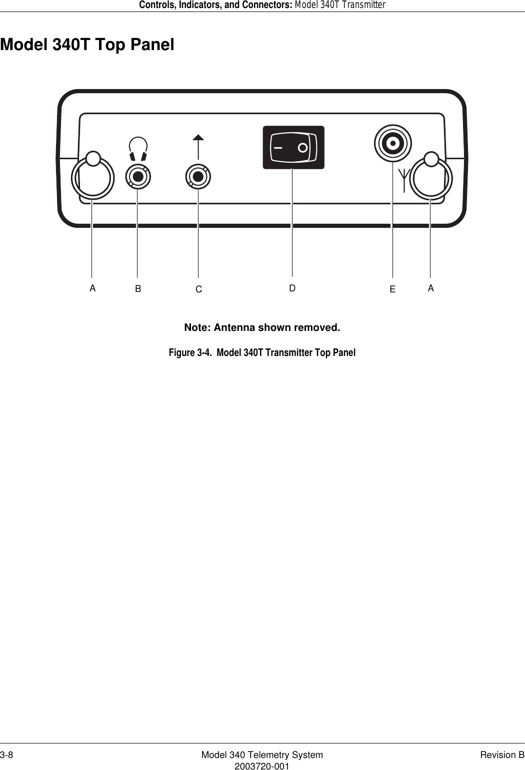
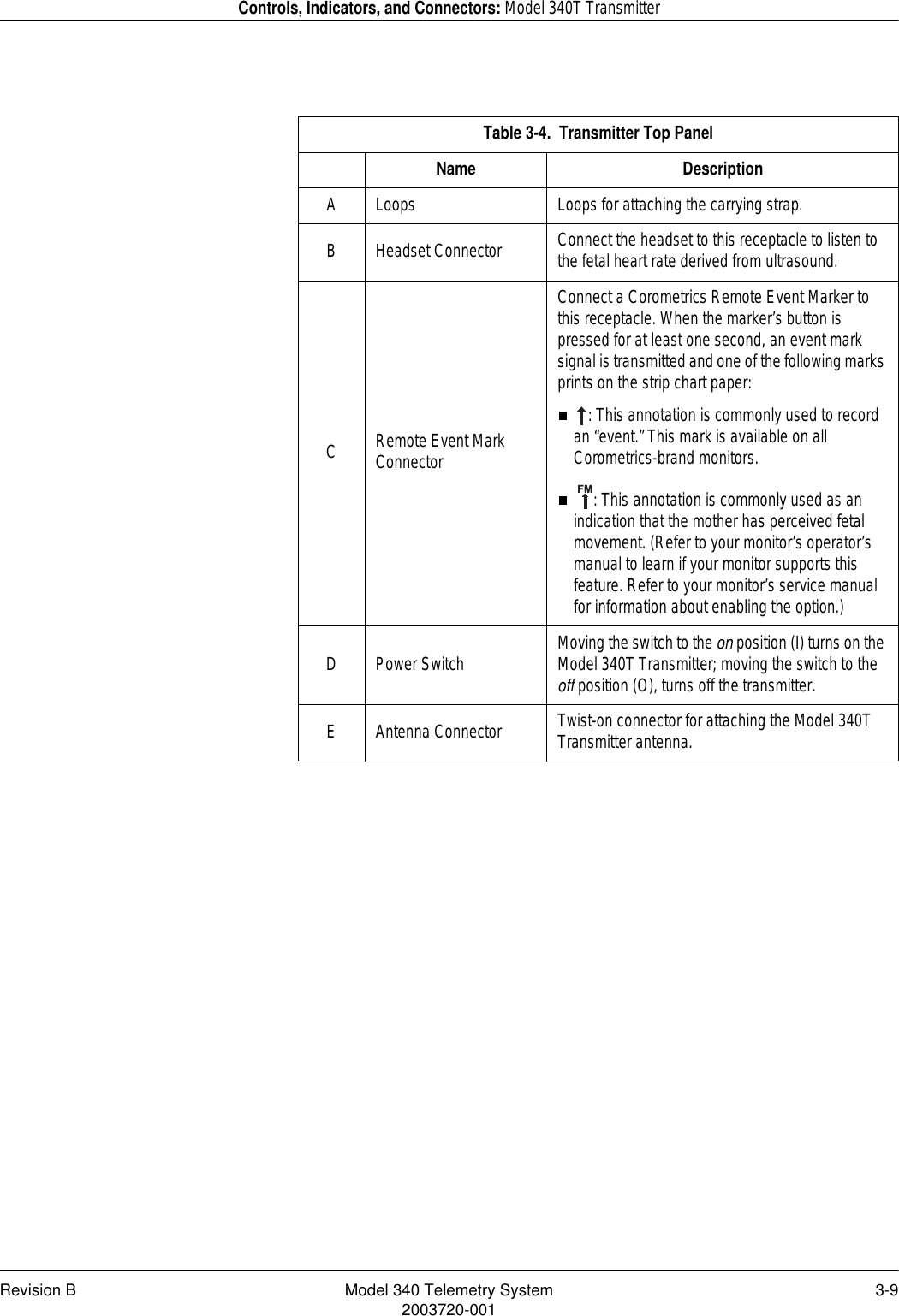
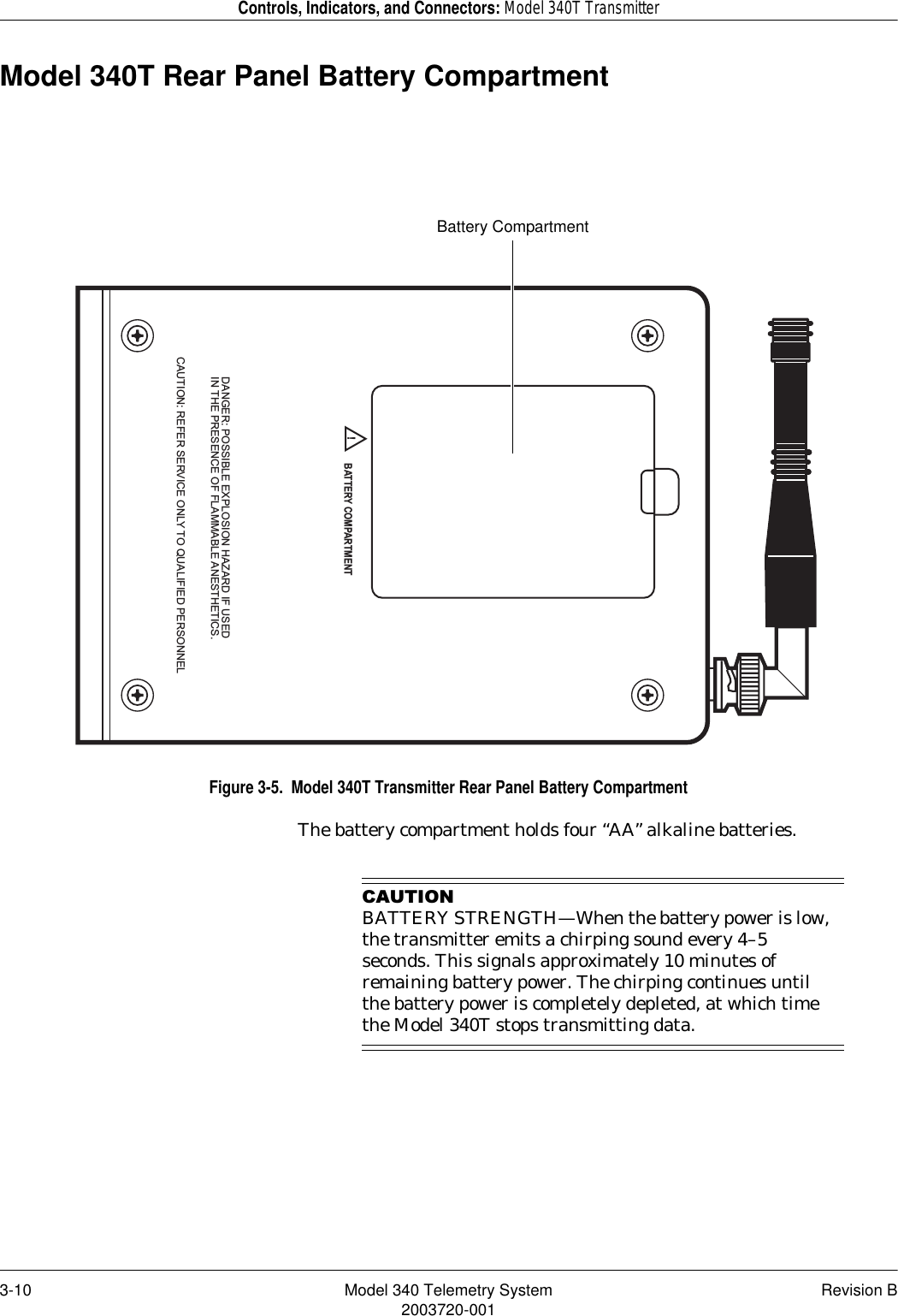
GE Medical Systems Information Technologies 340T Model 340 Medical Telemetry Transmitter User Manual

GE Medical Systems Information Technologies Inc. Model 340 Medical Telemetry Transmitter

Contents

User Manual

Corometrics Model 340OPERATOR’S MANUAL MANUAL P/N 2003720-001  REV. BIUPTOCOTelemetry Receiver340R+COROMETRICS~XXXCOROMETRICS340TTelemetry TransmitterREFER TO MANUAL FOR PROPER TRANSDUCERSULTRASOUND ECG UAXXX
Corometrics  and Marquette  are registered trademarks of GE Medical Systems Information Technologies.  GE is a registered trademark of General Electric Company.  All other product and brand names are trademarks or registered trademarks of their respective companies.  ©2000 GE Medical Systems Information Technologies.  All rights reserved.  No part of this manual may be reproduced without the permission of GE Medical Systems Information Technologies.GUARANTEEAll equipment sold by GE Medical Systems Information Technologies is fully guaranteed as to materials and workmanship for a period of 1 year.  Information Technologies reserves the right to perform guarantee service operations in its own factory, at an authorized repair station, or in the customer’s installation.Our obligation under this guarantee is limited to repairing, or, at our option, replacing any defective parts of our equipment, except fuses or batteries, without charge, if such defects occur in normal service.Claims for damage in shipment should be filed promptly with the transportation company.  All correspondence covering the instrument should specify the model and serial numbers.GE MEDICAL SYSTEMS Information TechnologiesA GE Medical Systems CompanyRevision A:  5/00Revision B:  11/00GE Medical Systems Information Technologies will make available on request such circuit diagrams, component diagrams, component parts lists, descriptions, calibration instructions, or other information which will assist the users or appropriately qualified technical personnel to repair those parts of the equipment which are classified by Information Technologies as repairable.  Refer to the service manual for further information.CAUTION:  In the United States of America, Federal Law restricts this device to sale by or on the order of a physician.!World Headquarters8200 West Tower AvenueMilwaukee, WI 53223 USATel: +414.355.5000800.558.5120 (US only)Fax: +414.355.3790Internet:  www.gemedicalsystems.comEurope / Middle East / AfricaPostfach 60 02 65D-79032 Freiburg GermanyTel: +49.761.45.43.0Fax: +49.761.45.43.233Asia11th Floor, The Lee Gardens33 Hysan AvenueCauseway Bay Hong KongTel: +852.2100.6300Fax: +852.2100.6292
Revision B Model 340 Telemetry System i2003720-001ContentsFigures . . . . . . . . . . . . . . . . . . . . . . . . . . . . . . . . . . . . . . . . . . vTables . . . . . . . . . . . . . . . . . . . . . . . . . . . . . . . . . . . . . . . . . .  vii1Safety . . . . . . . . . . . . . . . . . . . . . . . . . . . . . . . . . . . . . . . . .  1-1General Information . . . . . . . . . . . . . . . . . . . . . . . . . . . . . . . . . . . . . . . . . . . . . . . . . .  1-2General Use . . . . . . . . . . . . . . . . . . . . . . . . . . . . . . . . . . . . . . . . . . . . . . . . . . . . . .1-2Responsibility of the Manufacturer . . . . . . . . . . . . . . . . . . . . . . . . . . . . . . . . . . . . .1-2Definitions of Terminology . . . . . . . . . . . . . . . . . . . . . . . . . . . . . . . . . . . . . . . . . . . .  1-3Equipment Safety Information  . . . . . . . . . . . . . . . . . . . . . . . . . . . . . . . . . . . . . . . . .  1-4Warnings  . . . . . . . . . . . . . . . . . . . . . . . . . . . . . . . . . . . . . . . . . . . . . . . . . . . . . . . .1-4Cautions . . . . . . . . . . . . . . . . . . . . . . . . . . . . . . . . . . . . . . . . . . . . . . . . . . . . . . . .  1-7Equipment Symbols  . . . . . . . . . . . . . . . . . . . . . . . . . . . . . . . . . . . . . . . . . . . . . . . . .  1-8FCC Information . . . . . . . . . . . . . . . . . . . . . . . . . . . . . . . . . . . . . . . . . . . . . . . . . . . . .  1-9FCC Rules Compliance  . . . . . . . . . . . . . . . . . . . . . . . . . . . . . . . . . . . . . . . . . . . . .1-9FCC RF Exposure Compliance  . . . . . . . . . . . . . . . . . . . . . . . . . . . . . . . . . . . . . . .1-9FCC Service Information  . . . . . . . . . . . . . . . . . . . . . . . . . . . . . . . . . . . . . . . . . . . .1-92Introduction . . . . . . . . . . . . . . . . . . . . . . . . . . . . . . . . . . . .  2-1Product Summary  . . . . . . . . . . . . . . . . . . . . . . . . . . . . . . . . . . . . . . . . . . . . . . . . . . .  2-2Product Features . . . . . . . . . . . . . . . . . . . . . . . . . . . . . . . . . . . . . . . . . . . . . . . . . . . .  2-3
ii Model 340 Telemetry System Revision B2003720-0013Controls, Indicators, and Connectors . . . . . . . . . . . . . . .  3-1Model 340R Receiver . . . . . . . . . . . . . . . . . . . . . . . . . . . . . . . . . . . . . . . . . . . . . . . . .  3-2Model 340R Front Panel  . . . . . . . . . . . . . . . . . . . . . . . . . . . . . . . . . . . . . . . . . . . .3-2Model 340R Rear Panel . . . . . . . . . . . . . . . . . . . . . . . . . . . . . . . . . . . . . . . . . . . .  3-4Model 340T Transmitter   . . . . . . . . . . . . . . . . . . . . . . . . . . . . . . . . . . . . . . . . . . . . . .  3-6Model 340T Bottom Panel . . . . . . . . . . . . . . . . . . . . . . . . . . . . . . . . . . . . . . . . . . .3-6Model 340T Top Panel . . . . . . . . . . . . . . . . . . . . . . . . . . . . . . . . . . . . . . . . . . . . .  3-8Model 340T Rear Panel Battery Compartment  . . . . . . . . . . . . . . . . . . . . . . . . .  3-104Setup Procedures . . . . . . . . . . . . . . . . . . . . . . . . . . . . . . .  4-1Connecting the Receiver and Monitor . . . . . . . . . . . . . . . . . . . . . . . . . . . . . . . . . . .  4-2Models 115, 116, 118, 145, 150, 151, and 155 . . . . . . . . . . . . . . . . . . . . . . . . . . .4-2120 and 170 Series  . . . . . . . . . . . . . . . . . . . . . . . . . . . . . . . . . . . . . . . . . . . . . . .  4-5Setting Up the Model 340T Transmitter . . . . . . . . . . . . . . . . . . . . . . . . . . . . . . . . . .  4-7Installing Batteries  . . . . . . . . . . . . . . . . . . . . . . . . . . . . . . . . . . . . . . . . . . . . . . . . .4-7Attaching the Antenna  . . . . . . . . . . . . . . . . . . . . . . . . . . . . . . . . . . . . . . . . . . . . .  4-9Attaching the Carrying Strap  . . . . . . . . . . . . . . . . . . . . . . . . . . . . . . . . . . . . . . . . .4-9Performing a Functional Checkout  . . . . . . . . . . . . . . . . . . . . . . . . . . . . . . . . . . . .  4-10Initial Conditions . . . . . . . . . . . . . . . . . . . . . . . . . . . . . . . . . . . . . . . . . . . . . . . . . .4-10Testing the Radio Frequency . . . . . . . . . . . . . . . . . . . . . . . . . . . . . . . . . . . . . . . .4-10Testing the Ultrasound Functions  . . . . . . . . . . . . . . . . . . . . . . . . . . . . . . . . . . .  4-11Testing the ECG Functions  . . . . . . . . . . . . . . . . . . . . . . . . . . . . . . . . . . . . . . . .  4-13Testing the UA Functions . . . . . . . . . . . . . . . . . . . . . . . . . . . . . . . . . . . . . . . . . .  4-14Testing the Remote Event Marker Function  . . . . . . . . . . . . . . . . . . . . . . . . . . .  4-16Testing the Environment  . . . . . . . . . . . . . . . . . . . . . . . . . . . . . . . . . . . . . . . . . . .4-165Monitoring via Telemetry  . . . . . . . . . . . . . . . . . . . . . . . . .  5-1Suggestions for Ambulatory Monitoring . . . . . . . . . . . . . . . . . . . . . . . . . . . . . . . . .  5-2Monitoring Reminders . . . . . . . . . . . . . . . . . . . . . . . . . . . . . . . . . . . . . . . . . . . . . . . .  5-3General  . . . . . . . . . . . . . . . . . . . . . . . . . . . . . . . . . . . . . . . . . . . . . . . . . . . . . . . . .5-3Ultrasound  . . . . . . . . . . . . . . . . . . . . . . . . . . . . . . . . . . . . . . . . . . . . . . . . . . . . . . .5-3FECG . . . . . . . . . . . . . . . . . . . . . . . . . . . . . . . . . . . . . . . . . . . . . . . . . . . . . . . . . . .5-3Tocotransducer  . . . . . . . . . . . . . . . . . . . . . . . . . . . . . . . . . . . . . . . . . . . . . . . . . .  5-4IUP . . . . . . . . . . . . . . . . . . . . . . . . . . . . . . . . . . . . . . . . . . . . . . . . . . . . . . . . . . . . .5-4
Revision B Model 340 Telemetry System iii2003720-0016Maintenance  . . . . . . . . . . . . . . . . . . . . . . . . . . . . . . . . . . .  6-1General Cleaning Precautions  . . . . . . . . . . . . . . . . . . . . . . . . . . . . . . . . . . . . . . . . .  6-2Cleaning the Transmitter and Receiver . . . . . . . . . . . . . . . . . . . . . . . . . . . . . . . . . .  6-37Troubleshooting  . . . . . . . . . . . . . . . . . . . . . . . . . . . . . . . .  7-1Problem Chart  . . . . . . . . . . . . . . . . . . . . . . . . . . . . . . . . . . . . . . . . . . . . . . . . . . . . . .  7-28Supplies and Accessories  . . . . . . . . . . . . . . . . . . . . . . . .  8-1General  . . . . . . . . . . . . . . . . . . . . . . . . . . . . . . . . . . . . . . . . . . . . . . . . . . . . . . . . . . . .  8-2Paper . . . . . . . . . . . . . . . . . . . . . . . . . . . . . . . . . . . . . . . . . . . . . . . . . . . . . . . . . . . . . .  8-3Ultrasound  . . . . . . . . . . . . . . . . . . . . . . . . . . . . . . . . . . . . . . . . . . . . . . . . . . . . . . . . .  8-4FECG . . . . . . . . . . . . . . . . . . . . . . . . . . . . . . . . . . . . . . . . . . . . . . . . . . . . . . . . . . . . . .  8-5Tocotransducer  . . . . . . . . . . . . . . . . . . . . . . . . . . . . . . . . . . . . . . . . . . . . . . . . . . . . .  8-6IUPC  . . . . . . . . . . . . . . . . . . . . . . . . . . . . . . . . . . . . . . . . . . . . . . . . . . . . . . . . . . . . . .  8-7MECG  . . . . . . . . . . . . . . . . . . . . . . . . . . . . . . . . . . . . . . . . . . . . . . . . . . . . . . . . . . . . .  8-89Technical Specifications  . . . . . . . . . . . . . . . . . . . . . . . . .  9-1Model 340T Transmitter . . . . . . . . . . . . . . . . . . . . . . . . . . . . . . . . . . . . . . . . . . . . . . .  9-2Model 340R Receiver . . . . . . . . . . . . . . . . . . . . . . . . . . . . . . . . . . . . . . . . . . . . . . . . .  9-4
iv Model 340 Telemetry System Revision B2003720-001For your notes
Revision B Model 340 Telemetry System v2003720-001FiguresFigure 3-1.Model 340R Receiver Front Panel . . . . . . . . . . . . . . . . . . . . . . . . . . . . . . . . . . . . . . . .3-2Figure 3-2.Model 340R Receiver Rear Panel . . . . . . . . . . . . . . . . . . . . . . . . . . . . . . . . . . . . . . . .3-4Figure 3-3.Model 340T Transmitter Bottom Panel. . . . . . . . . . . . . . . . . . . . . . . . . . . . . . . . . . . . .3-6Figure 3-4.Model 340T Transmitter Top Panel . . . . . . . . . . . . . . . . . . . . . . . . . . . . . . . . . . . . . . .3-8Figure 3-5.Model 340T Transmitter Rear Panel Battery Compartment . . . . . . . . . . . . . . . . . . . .3-10Figure 4-1.Positioning the Receiver. . . . . . . . . . . . . . . . . . . . . . . . . . . . . . . . . . . . . . . . . . . . . . . .4-2Figure 4-2.Attaching the Receiver Antenna. . . . . . . . . . . . . . . . . . . . . . . . . . . . . . . . . . . . . . . . . .4-3Figure 4-3.Attaching the Receiver Interconnect Cables. . . . . . . . . . . . . . . . . . . . . . . . . . . . . . . . .4-3Figure 4-4.Attaching the Monitor Interconnect Cables. . . . . . . . . . . . . . . . . . . . . . . . . . . . . . . . . .4-4Figure 4-5.Attaching the Remote Mark Interconnect Cable. . . . . . . . . . . . . . . . . . . . . . . . . . . . . .4-4Figure 4-6.Attaching the Receiver Antenna. . . . . . . . . . . . . . . . . . . . . . . . . . . . . . . . . . . . . . . . . .4-5Figure 4-7.Attaching the Monitor Interconnect Cable to a 120 Series Monitor  . . . . . . . . . . . . . . .4-6Figure 4-8.Attaching the Monitor Interconnect Cable to a 170 Series Monitor  . . . . . . . . . . . . . . .4-6Figure 4-9.Accessing the Batteries . . . . . . . . . . . . . . . . . . . . . . . . . . . . . . . . . . . . . . . . . . . . . . . .4-7Figure 4-10.Transmitter Battery Orientation. . . . . . . . . . . . . . . . . . . . . . . . . . . . . . . . . . . . . . . . . . .4-8Figure 4-11.Attaching the Transmitter Antenna. . . . . . . . . . . . . . . . . . . . . . . . . . . . . . . . . . . . . . . .4-9
vi Model 340 Telemetry System Revision B2003720-001Figure 4-12.Attaching the Carrying Strap. . . . . . . . . . . . . . . . . . . . . . . . . . . . . . . . . . . . . . . . . . . . .4-9Figure 4-13.Applying Power. . . . . . . . . . . . . . . . . . . . . . . . . . . . . . . . . . . . . . . . . . . . . . . . . . . . . .4-10Figure 4-14.Connecting an Ultrasound Transducer. . . . . . . . . . . . . . . . . . . . . . . . . . . . . . . . . . . .4-11Figure 4-15.Connecting the Headset. . . . . . . . . . . . . . . . . . . . . . . . . . . . . . . . . . . . . . . . . . . . . . .4-12Figure 4-16.Connecting an FECG Cable/Legplate  . . . . . . . . . . . . . . . . . . . . . . . . . . . . . . . . . . . .4-13Figure 4-17.Connecting a Tocotransducer or IUPC Cable  . . . . . . . . . . . . . . . . . . . . . . . . . . . . . .4-14
Revision B Model 340 Telemetry System vii2003720-001TablesTable 1-1.Definitions of Terminology . . . . . . . . . . . . . . . . . . . . . . . . . . . . . . . . . . . . . . . . . . . . . .1-3Table 1-2.Equipment Symbols . . . . . . . . . . . . . . . . . . . . . . . . . . . . . . . . . . . . . . . . . . . . . . . . . . .1-8Table 2-1.Summary of Monitor Parameters . . . . . . . . . . . . . . . . . . . . . . . . . . . . . . . . . . . . . . . . .2-3Table 3-1.Receiver Front Panel . . . . . . . . . . . . . . . . . . . . . . . . . . . . . . . . . . . . . . . . . . . . . . . . . .3-3Table 3-2.Receiver Rear Panel. . . . . . . . . . . . . . . . . . . . . . . . . . . . . . . . . . . . . . . . . . . . . . . . . . .3-5Table 3-3.Transmitter Bottom Panel. . . . . . . . . . . . . . . . . . . . . . . . . . . . . . . . . . . . . . . . . . . . . . .3-7Table 3-4.Transmitter Top Panel . . . . . . . . . . . . . . . . . . . . . . . . . . . . . . . . . . . . . . . . . . . . . . . . .3-9Table 7-1.Troubleshooting . . . . . . . . . . . . . . . . . . . . . . . . . . . . . . . . . . . . . . . . . . . . . . . . . . . . . .7-2Table 8-1.General Supplies . . . . . . . . . . . . . . . . . . . . . . . . . . . . . . . . . . . . . . . . . . . . . . . . . . . . .8-2Table 8-2.Paper Supplies . . . . . . . . . . . . . . . . . . . . . . . . . . . . . . . . . . . . . . . . . . . . . . . . . . . . . . .8-3Table 8-3.Ultrasound Supplies . . . . . . . . . . . . . . . . . . . . . . . . . . . . . . . . . . . . . . . . . . . . . . . . . . .8-4Table 8-4.FECG Supplies. . . . . . . . . . . . . . . . . . . . . . . . . . . . . . . . . . . . . . . . . . . . . . . . . . . . . . .8-5Table 8-5.Tocotransducer Supplies . . . . . . . . . . . . . . . . . . . . . . . . . . . . . . . . . . . . . . . . . . . . . . .8-6Table 8-6.IUPC Supplies  . . . . . . . . . . . . . . . . . . . . . . . . . . . . . . . . . . . . . . . . . . . . . . . . . . . . . . .8-7Table 8-7.MECG Supplies . . . . . . . . . . . . . . . . . . . . . . . . . . . . . . . . . . . . . . . . . . . . . . . . . . . . . .8-8
viii Model 340 Telemetry System Revision B2003720-001For your notes
Revision B Model 340 Telemetry System 1-12003720-001Chapter 1Safety 1The information presented in this section is important for the safety of both the patient and operator and also serves to enhance equipment reliability.  This chapter describes how the terms Danger, Warning, Caution, Important, and Note are used throughout the manual.  In addition, standard equipment symbols are defined.  This section includes the following important information:General Information. . . . . . . . . . . . . . . . . . . . . . . . . . . . . . . . 1-2Definitions of Terminology  . . . . . . . . . . . . . . . . . . . . . . . . . . 1-3Equipment Safety Information . . . . . . . . . . . . . . . . . . . . . . . 1-4Equipment Symbols . . . . . . . . . . . . . . . . . . . . . . . . . . . . . . . . 1-8FCC Information  . . . . . . . . . . . . . . . . . . . . . . . . . . . . . . . . . . 1-9!
1-2 Model 340 Telemetry System Revision B2003720-001Safety: General InformationGeneral InformationGeneral UseIf any equipment is cold to the touch or below ambient temperature, allow it to stabilize before use.To ensure patient safety, use only parts and accessories manufactured or recommended by GE Medical Systems Information Technologies.  Parts and accessories used shall meet the requirements of IEC 601.1.1.Disposable devices are intended for single use only.  They should not be reused.Periodically, and whenever the integrity of the equipment is in doubt, test all functions.Refer to the "Maternal/Fetal Monitoring Operator’s Manual" for information concerning the limitations of internal and external fetal heart rate monitoring techniques.Responsibility of the ManufacturerGE Medical Systems Information Technologies (hereinafter Information Technologies) is responsible for the effects on safety, reliability, and performance if:assembly operations, extensions, readjustments, modifications, or repairs are carried out by persons authorized by Information Technologies;the electrical installation of the relevant room complies with the requirements of appropriate regulations; andthe equipment is used in accordance with the instructions for use.
Revision B Model 340 Telemetry System 1-32003720-001Safety: Definitions of TerminologyDefinitions of TerminologySix types of special notices are used throughout this manual.  They are:  Danger, Warning, Caution, Contraindication, Important, and Note.  The warnings and cautions in this safety section relate to the equipment in general and apply to all aspects of the equipment.  Be sure to read the other chapters because there are additional warnings and cautions which relate to specific features of the equipment.When grouped, warnings and cautions are listed alphabetically and do not imply any order of importance.Table 1-1.  Definitions of TerminologyDanger A DANGER notice indicates an imminently hazardous situation which, if not avoided, will result in death or serious injury.Warning A WARNING indicates a potentially hazardous situation which, if not avoided, could result in death or serious injury.CautionA CAUTION indicates a potentially hazardous situation which, if not avoided, may result in minor or moderate injury.  Cautions are also used to avoid damage to equipment.ContraindicationA CONTRAINDICATION describes any special symptom or circumstance that renders the use of a remedy or the carrying out of a procedure inadvisable, usually because of a risk.Important An IMPORTANT notice indicates an emphasized note.  It is something you should be particularly aware of;  something not readily apparent.Note A NOTE indicates a particular point of information; something on which to focus your attention.
1-4 Model 340 Telemetry System Revision B2003720-001Safety: Equipment Safety InformationEquipment Safety InformationWarnings:$51,1*6ACCIDENTAL SPILLS—In the event that fluids are accidentally spilled on the equipment, take the equipment out of operation and inspect for damage.APPLICATION—This equipment is not designed for direct cardiac connection.CONDUCTIVE CONNECTIONS—Avoid making any conductive connections to applied parts (patient connection) which are likely to degrade safety.CONDUCTIVE PARTS—Ensure that the conductive parts of the lead electrodes and associated connectors do not contact other conductive parts including earth.CONNECTIONS—The correct way to connect a patient to the transmitter is to plug the electrode leads into the patient cable which in turn connects to the transmitter.  The receiver is connected to the wall socket by the power cord.  Do not plug the electrode leads into the power cord, a wall socket, or an extension cord.DEFIBRILLATION—This equipment is not designed for use with defibrillators.ELECTRICAL SHOCK—To reduce the risk of electrical shock, do not remove equipment covers.  Refer servicing to qualified personnel.ELECTROMAGNETIC INTERFERENCE—Be aware that strong electromagnetic fields may interfere with equipment operation.  Interference prevents the clear reception of signals by the device.  If the hospital is close to a strong transmitter such as TV, AM or FM radio, police or fire stations, a HAM radio operator, an airport, or cellular phone, their signals could be picked up as signals by the equipment.  If you feel interference is affecting the equipment, contact your Service Representative to check the equipment in your environment.
Revision B Model 340 Telemetry System 1-52003720-001Safety: Equipment Safety Information:$51,1*6ELECTROSURGERY—The equipment is not designed for use with high-frequency surgical devices.  In addition, measurements may be affected in the presence of strong electromagnetic sources such as electrosurgery equipment.EXPLOSION HAZARD—Do not use this equipment in the presence of flammable anesthetics or inside an oxygen tent.GROUNDING—Do not defeat the three-wire grounding feature of the power cord by means of adaptors, plug modifications, or other methods.  A dangerous shock hazard to both patient and operator may result.INSTRUCTIONS—For continued and safe use of this equipment, it is necessary to follow all listed instructions.  However, the instructions provided in this manual in no way supersede established medical procedures concerning patient care.  The device does not replace observation and evaluation of the patient, at regular intervals, by a qualified care provider who will make diagnoses and decide on treatments and interventions.INTERFACING OTHER EQUIPMENT—Monitoring equipment must be interfaced with other types of medical equipment by qualified biomedical engineering personnel.  Be certain to consult manufacturers’ specifications to maintain safe operation.LEAKAGE CURRENT TEST—The interconnection of auxiliary equipment with this device may increase the total leakage current. When interfacing with other equipment, a test for leakage current must be performed by qualified biomedical engineering personnel before using with patients.  Serious injury or death could result if the leakage current exceeds applicable standards.  The use of accessory equipment not complying with the equivalent safety requirements of this equipment may lead to a reduced level of safety of the resulting system.  Consideration relating to the choice shall include:  use of the accessory in the patient vicinity; and evidence that the safety certification of the accessory has been performed in accordance with the appropriate IEC 601.1 and/or IEC 601.1.1 harmonized national standard.
1-6 Model 340 Telemetry System Revision B2003720-001Safety: Equipment Safety Information:$51,1*6LINE ISOLATION MONITOR TRANSIENTS—Line isolation monitor transients may resemble actual cardiac waveforms, and thus cause incorrect heart rate determinations and alarm activation (or inhibition).MRI USE—Do not use the equipment during MRI scanning; conducted current could potentially cause burns.PATIENT CABLES AND LEADWIRES—Do not use patient cables and electrode leads that permit direct connection to electrical sources.  Use only “safety” cables and leadwires.  Use of non-safety patient cables and lead wires creates risk of inappropriate electrical connection which may cause patient shock or death.PACEMAKER PATIENTS—Rate meters may continue to count the pacemaker rate during occurrences of cardiac arrest or some arrhythmias.  Do not rely entirely upon rate meter alarms.  Keep pacemaker patients under close surveillance.  Refer to your monitor’s operator’s manual for disclosure of the pacemaker pulse rejection capability.SIMULTANEOUS DEVICES—Do not simultaneously connect more than one device that uses electrodes to detect ECG and/or respiration to the same patient.  Use of more than one device in this manner may cause improper operation of one or more of the devices.STRANGULATION—Make sure all patient cables, leadwires, and tubing are positioned away from the patient’s head to minimize the risk of accidental strangulation.
Revision B Model 340 Telemetry System 1-72003720-001Safety: Equipment Safety InformationCautions&$87,216ANNUAL SERVICING—For continued safety and performance of the equipment, it is recommended that the calibration, accuracy, and electrical safety of the equipment be verified on an annual basis by an Information Technologies Service Representative.DAILY INSPECTION—It is essential that the equipment and accessories be inspected prior to every use.ENVIRONMENT—The performance of the equipment has not been tested in certain areas, such as x-ray and imaging suites.  The equipment is not recommended for use in these environments.PERFORMANCE—Report all problems experienced with the equipment.  If the equipment is not working properly, contact your Service Representative for service.  The equipment should not be used if it is not working properly.
1-8 Model 340 Telemetry System Revision B2003720-001Safety: Equipment SymbolsEquipment SymbolsThe following is a list of symbols used on products manufactured by Information Technologies.  Some symbols may not appear on your equipment.Table 1-2.  Equipment SymbolsATTENTION:  Consult accompanying documents.TYPE B EQUIPMENT.  Type B equipment is suitable for intentional external and internal application to the patient, excluding direct cardiac application.TYPE BF EQUIPMENT.  Type BF  equipment is suitable for intentional external and internal application to the patient, excluding direct cardiac application.  Type BF equipment has an F-type applied part.DEFIBRILLATOR-PROOF TYPE BF EQUIPMENT: Type BF equipment is suitable for intentional external and internal application to the patient, excluding direct cardiac application.  Type BF equipment is type B equipment with an F-type isolated (floating) part.  The paddles indicate the equipment is defibrillator proof.ALTERNATING CURRENT (AC).IPX1 DRIP PROOF.EQUIPOTENTIALITY.OPOWER OFF: disconnection from the mains.IPOWER ON: connection to the mains.!
Revision B Model 340 Telemetry System 1-92003720-001Safety: FCC InformationFCC InformationFCC Rules ComplianceThis equipment complies with Part 15 of FCC rules. Operation is subject to the condition that this device does not cause harmful interference.FCC RF Exposure Compliance,03257$17RF EXPOSURE—To comply with FCC RF exposure compliance requirements, users should avoid grasping the antenna for any extended period of time while the device is in operation.FCC Service InformationServicing the radio frequency transmitter and receiver sections of the Model 340 Telemetry System requires an FCC General Radio Telephone License.Any changes or modifications made to the Model 340 Telemetry System that are not expressly approved by Information Technologies, could void the user’s authority to operate this equipment.
1-10 Model 340 Telemetry System Revision B2003720-001For your notes
Revision B Model 340 Telemetry System 2-12003720-001Chapter 2Introduction 2This chapter contains the following information:Product Summary  . . . . . . . . . . . . . . . . . . . . . . . . . . . . . . . . . 2-2Product Features . . . . . . . . . . . . . . . . . . . . . . . . . . . . . . . . . . 2-3
2-2 Model 340 Telemetry System Revision B2003720-001Introduction: Product SummaryProduct SummaryThe Corometrics Model 340 Telemetry System (Model 340R Receiver and Model 340T Transmitter) provides a wireless means of transmitting heart rate and uterine activity signals from an ambulatory mother to a bedside fetal or maternal/fetal monitor. The system operates with the following Corometrics brand monitors; if your monitor is not listed, check with your saleperson or service representative for a more current list.Model 115Model 116Model 118120 Series*Model 145Model 150Model 151Model 155170 Series127(The Model 340 Telemetry System does not support fetal movement detection.The system monitors ultrasound, ECG (FECG or MECG), and uterine activity (TOCO or IUPC) signals individually or in combination. Refer to your monitor’s operator’s manual as needed.*A 120 Series Monitor requires a Communications Board in order to interface to a Model 340 Telemetry System. If your monitor does not have this option, an upgrade kit is available as cat. no. (REF) 1559BAO. Contact your Service Representative for more information.
Revision B Model 340 Telemetry System 2-32003720-001Introduction: Product FeaturesProduct FeaturesThe following is a summary of product features:Battery operated transmitter provides up to 20 hours* of continuous transmission when operated with fresh batteries.A Low Battery indicator, accompanied by an audio indicator, signals an impending low-battery condition.A transmitter headset* allows the patient or staff to hear the ultrasonically detected heartbeats for reassurance as well as to verify proper transducer placement.A Signal Quality indicator verifies the strength of the radio transmission signal.Transducers are quickly and easily interchangeable amongst the Model 340 Telemetry System and most Corometrics brand monitors:Models 116, 118, 150, 151, 155, and 170 Series: transducers are interchangeable.120 Series: ECG rectangular connector cables are not compatible; round connector cables are compatible.Models 115 and 145: cat. no. (REF) 5600 ultrasound transducers cannot be used with a Model 340. Use only cat. no. (REF) 5700 transducers when the using a Model 115 or 145 with a Model 340 Telemetry System.Provides simultaneous monitoring of two heart rates (twins or maternal/fetal) when used with a monitor supporting these parameters. Refer to Table 2-1 for a summary of monitor parameters.,03257$17INSTRUCTIONS—The operator should review and be familiar with the operator’s manual for the fetal or maternal/fetal monitor as well as the "Maternal/Fetal Monitoring Operator’s Manual".*Use of the headset will deplete the batteries more rapidly. Table 2-1.  Summary of Monitor Parameters115 116 118 126 128 129 145 150 151 151D 155 171 172 173TOCO ááááááááá á ááááIUPC áááááá áá áUS ááááááááá á ááááFECG áááááá áá áMECG ááá ááá
2-4 Model 340 Telemetry System Revision B2003720-001For your notes
Revision B Model 340 Telemetry System 3-12003720-001Chapter 3Controls, Indicators, and Connectors 3This section describes all controls, indicators, and connectors on a Model 340 Telemetry System.Model 340R Receiver . . . . . . . . . . . . . . . . . . . . . . . . . . . . . . . 3-2Model 340T Transmitter . . . . . . . . . . . . . . . . . . . . . . . . . . . . 3-6
3-2 Model 340 Telemetry System Revision B2003720-001Controls, Indicators, and Connectors: Model 340R ReceiverModel 340R ReceiverModel 340R Front PanelFigure 3-1.  Model 340R Receiver Front PanelIUPTOCOTelemetry Receiver340R+COROMETRICS~XXXABCDE
Revision B Model 340 Telemetry System 3-32003720-001Controls, Indicators, and Connectors: Model 340R ReceiverTable 3-1.  Receiver Front PanelName DescriptionAUA Mode Selector SwitchThis switch communicates the active uterine activity mode to the fetal or maternal/fetal monitor:When monitoring with a tocotransducer, set the switch to the TOCO position.When monitoring with an intrauterine pressure catheter, set the switch to the IUP position.B Channel NumberThe channel number is the customer-designated receiving frequency of the Model 340R Receiver. For each telemetry system, the channel number of the receiver must be identical to the channel number of the transmitter. Also, if you have more than one telemetry system, or other RF devices, each system must have a unique channel number.CPower Switch and IndicatorThe Power switch turns the receiver on (I) and off (O). When set to on, the green Power indicator illuminates.D Low Battery IndicatorThe red Low Battery indicator flashes when you have approximately 10 minutes of Model 340T Transmitter battery power remaining. The Low Battery indicator stops flashing and lights continuously as soon as the battery is depleted.E Signal IndicatorThe green Signal indicator lights continuously when the receiver is accepting radio frequency signals from the transmitter. The Signal indicator flashes if the signal strength is weak or marginal.
3-4 Model 340 Telemetry System Revision B2003720-001Controls, Indicators, and Connectors: Model 340R ReceiverModel 340R Rear PanelNote: Antenna shown removed.Figure 3-2.  Model 340R Receiver Rear PanelANTENNAOUTPUTS TO MONITORCONNECT TOCOROMETRICSMONITORS ONLYULTRASOUND ECG UA!WARNING: TO REDUCE FIRE HAZARDREPLACE FUSE AS MARKED.CAUTION!120Vac~120V ~ 50-60HZ 30W0.25A SLOW BLOWAEDCB
Revision B Model 340 Telemetry System 3-52003720-001Controls, Indicators, and Connectors: Model 340R ReceiverTable 3-2.  Receiver Rear PanelName DescriptionAAC Line Connector and Fuseholder ModuleThis module houses the AC-line input connector and the main fuses for the Model 340R Receiver:100–120 VAC: requires two, 1 A slow-blow fuses.220–240 VAC: requires two, 1 A time-lag fuses.BAuxiliary Output ConnectorThis connector is used with 120 and 170 Series Monitors only. Do not use this connection method for Models 115, 116, 118, 145, 150, 151, and 155 Monitors.This connector outputs the US, ECG, UA, and Mark signals, acquired by telemetry, to a 120 or 170 Series Monitor. See page 4-5 for complete interconnection details.As soon as any telemetry mode is detected, the front panel of the 120 or 170 Series Monitor is disabled and all front panel inputs are ignored. In other words, telemetry and monitor modes cannot be “mixed and matched’; you must use telemetry only or direct monitoring only.For proper operation with a 170 Series Monitor, disconnect all transducers from the front panel of the monitor.CUS, ECG, UA, and Mark ConnectorsThese connectors are used with Models 115, 116, 118, 145, 150, 151, and 155 Monitors only. Do not use this connection method for 120 and 170 Series Monitors.Each connector outputs the respective signal, acquired by telemetry, to the fetal or maternal/fetal monitor:US: light grey connector which outputs the ultrasound signal.ECG: grey connector which outputs the FECG or MECG signal.UA: white connector which outputs the TOCO or IUPC signal.Mark: connector which outputs the Event Mark signal.See page 4-2 for complete interconnection details.D Antenna Connector Twist-on connector for attaching the Model 340R Receiver antenna.E Equipotential Lug Binding post terminal directly connected to the chassis for use as an equipotentiality connection.
3-6 Model 340 Telemetry System Revision B2003720-001Controls, Indicators, and Connectors: Model 340T TransmitterModel 340T TransmitterModel 340T Bottom PanelFigure 3-3.  Model 340T Transmitter Bottom PanelACB
Revision B Model 340 Telemetry System 3-72003720-001Controls, Indicators, and Connectors: Model 340T TransmitterTable 3-3.  Transmitter Bottom PanelName DescriptionA Ultrasound InputConnect a Corometrics 5700 Series pulsed Doppler ultrasound transducer to this light gray receptacle.Corometrics 5600 Series continuous-wave ultrasound transducers are not compatible with the Model 340 Telemetry System. The 5600 Series Transducer was designed for use with Models 115 and 145 Monitors and Models 320 and 330 Telemetry Systems.B ECG InputConnect an FECG cable/legplate or MECG cable plug to this grey receptacle. This connector is compatible with all round-connector FECG/MECG patient cables used with Corometrics-brand monitors.C UA Input Connect a tocotransducer, IUPC, or strain gauge transducer plug to this white receptacle. Contact your Sales Representative about compatibility.
3-8 Model 340 Telemetry System Revision B2003720-001Controls, Indicators, and Connectors: Model 340T TransmitterModel 340T Top PanelNote: Antenna shown removed.Figure 3-4.  Model 340T Transmitter Top PanelABCDEA
Revision B Model 340 Telemetry System 3-92003720-001Controls, Indicators, and Connectors: Model 340T TransmitterTable 3-4.  Transmitter Top PanelName DescriptionA Loops Loops for attaching the carrying strap.B Headset Connector Connect the headset to this receptacle to listen to the fetal heart rate derived from ultrasound.CRemote Event Mark ConnectorConnect a Corometrics Remote Event Marker to this receptacle. When the marker’s button is pressed for at least one second, an event mark signal is transmitted and one of the following marks prints on the strip chart paper:: This annotation is commonly used to record an “event.” This mark is available on all Corometrics-brand monitors.: This annotation is commonly used as an indication that the mother has perceived fetal movement. (Refer to your monitor’s operator’s manual to learn if your monitor supports this feature. Refer to your monitor’s service manual for information about enabling the option.)D Power Switch Moving the switch to the on position (I) turns on the Model 340T Transmitter; moving the switch to the off position (O), turns off the transmitter.E Antenna Connector Twist-on connector for attaching the Model 340T Transmitter antenna.FM
3-10 Model 340 Telemetry System Revision B2003720-001Controls, Indicators, and Connectors: Model 340T TransmitterModel 340T Rear Panel Battery CompartmentFigure 3-5.  Model 340T Transmitter Rear Panel Battery CompartmentThe battery compartment holds four “AA” alkaline batteries.&$87,21BATTERY STRENGTH—When the battery power is low, the transmitter emits a chirping sound every 4–5 seconds. This signals approximately 10 minutes of remaining battery power. The chirping continues until the battery power is completely depleted, at which time the Model 340T stops transmitting data.DANGER: POSSIBLE EXPLOSION HAZARD IF USEDIN THE PRESENCE OF FLAMMABLE ANESTHETICS.CAUTION: REFER SERVICE ONLY TO QUALIFIED PERSONNEL!BATTERY COMPARTMENTBattery Compartment
Revision B Model 340 Telemetry System 4-12003720-001Chapter 4Setup Procedures 4This section contains step-by-step instructions for connecting and testing your Model 340 Telemetry System.,03257$17CHANNEL NUMBERS—Ensure that the Model 340R Receiver and Model 340T Transmitter are operating on the same frequency; the channel numbers must be identical. The channel number label is located on the front of the Model 340R and on the side of the Model 340T.If you have more than one telemetry system, make sure that each transmitter/receiver pair operates on a unique frequency.Connecting the Receiver and Monitor. . . . . . . . . . . . . . . . . . 4-2Setting Up the Model 340T Transmitter  . . . . . . . . . . . . . . . 4-7Performing a Functional Checkout. . . . . . . . . . . . . . . . . . . 4-10
4-2 Model 340 Telemetry System Revision B2003720-001Setup Procedures: Connecting the Receiver and MonitorConnecting the Receiver and MonitorThere are two types of interconnection methods depending on the model of your fetal or maternal/fetal monitor. Check your monitor model number prior to making any connections.Models 115, 116, 118, 145, 150, 151, and 1551. Turn off both the monitor and the Model 340R Receiver.2. Place the receiver on top of, or near, the monitor.Note: Model 118 shown.Figure 4-1.  Positioning the ReceiverMATERNAL / FETAL MONITOR118MaternalBPULTRASOUND ULTRASOUND 2 ECGECGUAECG AND  SpO2  ELECTRICALL ELECTRICALLY ISOLATEDREFER TO  MANUAL  FOR  PROPER  TRANSDUCERSVolume Volume BP Stop Setup SelectBP Start StartBP AutoAlarmAlarmCancelMaternalMaternalSpO24305AAOCOROMETRICS MEDICAL SYSTEMS,4305AAOFHR bpm90120150180240210IUPTOCOTelemetry Receiver 340R+COROMETRICXXX
Revision B Model 340 Telemetry System 4-32003720-001Setup Procedures: Connecting the Receiver and Monitor3. Insert the receiver antenna (longer of the two antennas) into the rear panel Antenna connector  ; rotate the attachment collar in a clockwise direction until snug.127(A Remote Antenna Bracket, cat. no. (REF) 1441AAO, is available for attaching the antenna when the receiver will be enclosed in a cart or cabinet. Refer to the Installation Instructions, part no. (REF) 14153AA, included with the bracket; or contact your Biomedical Engineering Department for assistance. To attach the antenna to the BNC connector on the bracket, rotate the antenna attachment collar in a clockwise direction until snug.Figure 4-2.  Attaching the Receiver Antenna4. Connect the appropriate ultrasound, ECG, and uterine activity interconnect cables to the corresponding Ultrasound, ECG, and UA connectors on the receiver rear panel.Figure 4-3.  Attaching the Receiver Interconnect CablesANTENNAOUTPUTS TO MONITORCONNECT TOCOROMETRICSMONITORS ONLYULTRASOUND ECG UA!WARNING: TO REDUCE FIRE HAZARDREPLACE FUSE AS MARKED.CAUTION!120Vac~120V ~ 50-60HZ 30W0.25A SLOW BLOW
4-4 Model 340 Telemetry System Revision B2003720-001Setup Procedures: Connecting the Receiver and Monitor5. Connect the remaining ends of the cables to the color-coded Ultrasound, ECG, and UA input connectors on the front or side panel of the monitor.Note: Model 118 shown.Figure 4-4.  Attaching the Monitor Interconnect Cables6. Connect one end of the Remote Event Mark interconnect cable to the  connector on the receiver rear panel; connect the other end to the Remote Marks   connector on the rear or side panel of the monitor.Note: Model 118 shown.Figure 4-5.  Attaching the Remote Mark Interconnect Cable
Revision B Model 340 Telemetry System 4-52003720-001Setup Procedures: Connecting the Receiver and Monitor120 and 170 Series,03257$17120 SERIES COMMUNICATIONS OPTION—A 120 Series Monitor requires a Communications Board in order to interface to a Model 340 Telemetry System. If your monitor does not have this option, an upgrade kit is available as cat. no. (REF) 1559BAO. Contact your Service Representative for more information.1. Turn off both the monitor and the Model 340R Receiver.2. Place the receiver on top of, or near, the monitor.3. Insert the receiver antenna (longer of the two antennas) into the rear panel Antenna connector  ; rotate the attachment collar in a clockwise direction until snug.127(A Remote Antenna Bracket, cat. no. (REF) 1441AAO, is available for attaching the antenna when the receiver will be enclosed in a cart or cabinet. Refer to the Installation Instructions, part no. (REF) 14153AA, included with the bracket; or contact your Biomedical Engineering Department for assistance. To attach the antenna to the BNC connector on the bracket, rotate the antenna attachment collar in a clockwise direction until snug.Figure 4-6.  Attaching the Receiver AntennaANTENNAOUTPUTS TO MONITORCONNECT TOCOROMETRICSMONITORS ONLYULTRASOUND ECG UA!WARNING: TO REDUCE FIRE HAZARDREPLACE FUSE AS MARKED.CAUTION!120Vac~120V ~ 50-60HZ 30W0.25A SLOW BLOW
4-6 Model 340 Telemetry System Revision B2003720-001Setup Procedures: Connecting the Receiver and Monitor4. Plug one end of the interconnection cable into the Auxiliary Output connector (Connect to Corometrics Monitor Only) on the receiver rear panel.5. Plug the other end into the respective telemetry connector on the real panel of the monitor:120 Series: Connect to J101.Figure 4-7.  Attaching the Monitor Interconnect Cable to a 120 Series Monitor170 Series: Connect to the receptacle labeled  .Figure 4-8.  Attaching the Monitor Interconnect Cable to a 170 Series MonitorCAUTION: FEDERALLAW RESTRICTSTHISDEVICE TO SALE BYOR ON THE ORDEROFA PHYSICIAN.LEG PLTESTERCONNECT TOCOROMETRICSDATA ENTRY SYSTEMSONLYCONNECT TOCOROMETRICSSERIES 400 MONITORSONLYCONNECT TO COROMETRICSTELEMETRY RECEIVERSONLYJ102J103J101ANTENNAOUTPUTS TO MONITORCONNECT TOCOROMETRICSMONITORS ONLYULTRASOUND ECG UA!WARNING: TO REDUCE FIRE HAZARDREPLACE FUSE AS MARKED.CAUTION!120Vac~120V ~ 50-60HZ 30W0.25A SLOW BLOWPUSHRS2321RS2322ANTENNAOUTPUTS TO MONITORCONNECT TOCOROMETRICSMONITORS ONLYULTRASOUND ECG UA!WARNING: TO REDUCE FIRE HAZARDREPLACE FUSE AS MARKED.CAUTION!120Vac~120V ~ 50-60HZ 30W0.25A SLOW BLOW
Revision B Model 340 Telemetry System 4-72003720-001Setup Procedures: Setting Up the Model 340T TransmitterSetting Up the Model 340T TransmitterInstalling Batteries127(If the Model 340T Transmitter will not be used for an extended period of time, remove the batteries to prevent damage due to battery leakage.1. Turn off the Model 340T Transmitter.2. Locate the battery compartment cover plate on the transmitter rear panel.3. Remove the cover plate. Use your thumb to lift the raised end.Figure 4-9.  Accessing the Batteries4. Remove the depleted batteries.&$87,21BATTERY DISPOSAL—Follow the battery manufacturer’s recommendations or your hospital policy for the disposal of used batteries.DANGER: POSSIBLE EXPLOSION HAZARD IF USEDIN THE PRESENCE OF FLAMMABLE ANESTHETICS.CAUTION: REFER SERVICE ONLY TO QUALIFIED PERSONNEL!BATTERY COMPARTMENTBattery CompartmentLift Here
4-8 Model 340 Telemetry System Revision B2003720-001Setup Procedures: Setting Up the Model 340T Transmitter5. Insert four new “AA” alkaline batteries, observing the polarity markings in the battery compartment.Note: Antenna shown removedFigure 4-10.  Transmitter Battery Orientation6. Replace the battery compartment cover plate. Insert the lip of the cover in the lower portion of the compartment opening; swing the other end of the cover down and snap into place.BATTERY COMPARTMENT!DANGER: POSSIBLE EXPLOSION HAZARD IF USEDIN THE PRESENCE OF FLAMMABLE ANESTHETICS.CAUTION: REFER SERVICE ONLY TO QUALIFIED PERSONNEL++++
Revision B Model 340 Telemetry System 4-92003720-001Setup Procedures: Setting Up the Model 340T TransmitterAttaching the Antenna Insert the transmitter antenna (shorter of the two antennas) into the top panel Antenna connector; rotate the attachment collar in a clockwise direction until snug.Figure 4-11.  Attaching the Transmitter AntennaAttaching the Carrying StrapSecure the metal clips at each end of the carrying strap to the belt attachment loops on each side of the transmitter.Figure 4-12.  Attaching the Carrying StrapDANGER: POSSIBLE EXPLOSION HAZARD IF USEDIN THE PRESENCE OF FLAMMABLE ANESTHETICS.CAUTION: REFER SERVICE ONLY TO QUALIFIED PERSONNEL!BATTERY COMPARTMENT
4-10 Model 340 Telemetry System Revision B2003720-001Setup Procedures: Performing a Functional CheckoutPerforming a Functional CheckoutInitial ConditionsTurn on the Model 340T Transmitter, the Model 340R Receiver, and the monitor attached to the receiver.Figure 4-13.  Applying PowerTesting the Radio Frequency1. Check the status of the Signal indicator   on the Model 340R Receiver:Continuous Green: indicates the transmitter is active and the batteries have adequate capacity.Flashing Green: indicates the signal strength is weak or marginal.2. Check the status of the Battery indicator   on the Model 340R Receiver:Off: the transmitter batteries have power.Flashing Red: the transmitter batteries are low and should be replaced before further patient use.Continuous Red: the transmitter batteries are depleted.++
Revision B Model 340 Telemetry System 4-112003720-001Setup Procedures: Performing a Functional CheckoutTesting the Ultrasound Functions,03257$17TRANSDUCER TYPE—Use only Corometrics 5700 Series Ultrasound Transducers with the Model 340 Telemetry System.1. Plug an ultrasound transducer into the Ultrasound connector on the transmitter.Figure 4-14.  Connecting an Ultrasound Transducer2. Verify the following:Models 115, 145: The corresponding FHR display reads 0 BPM.Models 116, 118, 150, 151, 118, 155 and Series 120, 170: The corresponding FHR display shows “– – –”.If the display fails to illuminate, ensure that the corresponding interconnection cable is firmly attached to both the monitor and the receiver.3. Use your finger to gently rub the ultrasound transducer face in a rhythmic manner. Try to maintain a steady rate and verify the following on the monitor:the corresponding FHR display value responds to the rubbing;the corresponding FHR heartbeat indicator   responds to the input; andthe ultrasound audio tones are synchronous with the transducer stroking.
4-12 Model 340 Telemetry System Revision B2003720-001Setup Procedures: Performing a Functional Checkout4. Plug the headset into the transmitter’s headset connector  .Figure 4-15.  Connecting the Headset5. Rub the face of the ultrasound transducer. Verify that you can hear ultrasound audio tones from both sides of the headset.
Revision B Model 340 Telemetry System 4-132003720-001Setup Procedures: Performing a Functional CheckoutTesting the ECG Functions127(Not all monitors have a legplate tester. Refer to your monitor’s operator’s manual for complete information.1. Slide the legplate into the monitor’s Legplate Tester jack and hold firmly in place. (The legplate tester uses an internal ECG simulator circuit for testing cable/legplate assemblies. The tester simulates a signal of 120 BPM ± 1 BPM.)2. Plug the other end into the ECG connector on the transmitter. Verify the following on the monitor:the corresponding FHR value reads 120 BPM;the corresponding FHR heartbeat indicator   flashes at a rate of 120 times per minute; andthe ECG “beep” is heard from the speaker.Figure 4-16.  Connecting an FECG Cable/Legplate
4-14 Model 340 Telemetry System Revision B2003720-001Setup Procedures: Performing a Functional CheckoutTesting the UA Functions1. Place the receiver’s UA Mode Selector switch in the TOCO position.,03257$17TRIMLINE TOCOTRANSDUCERS—If the monitor is on when you connect or re-connect a Trimline Tocotransducer to the UA connector, you must wait at least 10 seconds before pressing the UA Reference button. If the monitor is off, you must wait at least 10 seconds from the time the monitor is powered on.2. Plug a tocotransducer into the transmitter’s UA connector. Verify the following on the monitor:If the monitor has a UA display: the display reads an arbitrary pressure value.If the monitor does not have a UA display: turn on the strip chart recorder and check that TOCO prints on the paper’s mode annotation line.Figure 4-17.  Connecting a Tocotransducer or IUPC Cable,03257$17DEFAULT REFERENCE VALUE—Most monitors have a default UA reference of 10 relative units. Take into consideration that newer model monitor’s can be configured to store a custom default value.
Revision B Model 340 Telemetry System 4-152003720-001Setup Procedures: Performing a Functional Checkout3. Press the monitor’s UA Reference button to set the UA value to 10 relative units. Verify the following on the monitor:If the monitor has a UA display: the display reads 10 relative units.If the monitor does not have a UA display: turn on the strip chart recorder and check that the UA REF message and TOCO mode annotation both print on the paper.4. Apply gentle pressure to the tocotransducer pressure sensing button and verify that the monitor (display or uterine activity trace) responds to the pressure input. Increasing force should produce an increasing value and vice versa.If no pressure changes are recorded, ensure that the corresponding interconnection cable is firmly attached to both the monitor and the receiver.5. This step applies to monitors which support IUP monitoring. Place the receiver’s UA Mode Selector switch in the IUP position. Verify the following on the monitor:If the monitor has a mode indicator: the IUP mode should be indicated.If the monitor does not have a mode indicator: turn on the strip chart recorder and check that the IUP mode annotation prints on the paper.127(Place the UA Mode Selector switch back in the TOCO position unless you plan to monitor with an IUPC.
4-16 Model 340 Telemetry System Revision B2003720-001Setup Procedures: Performing a Functional CheckoutTesting the Remote Event Marker Function1. Plug the Remote Event Marker into the transmitter’s Remote Marks connector.2. Turn on the monitor’s strip chart recorder.3. Press the Remote Event Marker’s pushbutton for at least one second. Verify that an appropriate mark is printed on the paper:: This annotation is commonly used to record an “event.” This mark is available on all Corometrics-brand monitors.: This annotation is commonly used as an indication that the mother has perceived fetal movement. (Refer to your monitor’s operator’s manual to learn if your monitor supports this feature. Refer to your monitor’s service manual for information about enabling the option.)Testing the EnvironmentDecide on which areas of your facility will be used for ambulatory monitoring. Test each location separately to rule out rooms that are restricted due to metal structures blocking signal transmission.FM
Revision B Model 340 Telemetry System 5-12003720-001Chapter 5Monitoring via Telemetry5This section provides a brief overview of telemetry monitoring procedures. Refer to the "Maternal/Fetal Monitoring Operator’s Manual" for patient application information. Also refer to your monitor’s operator’s manual.Suggestions for Ambulatory Monitoring. . . . . . . . . . . . . . . . 5-2Monitoring Reminders. . . . . . . . . . . . . . . . . . . . . . . . . . . . . . 5-3
5-2 Model 340 Telemetry System Revision B2003720-001Monitoring via Telemetry: Suggestions for Ambulatory MonitoringSuggestions for Ambulatory Monitoring,03257$17DESIGNATED AREAS—Show the patient the areas that are within signal range and where signal reception is clear.1. Instruct the patient to wear the Model 340T Transmitter with the antenna pointed towards the Model 340R Receiver when possible.2. Adjust the carrying strap to a comfortable length.3. Encourage the patient to walk in a smooth, gliding motion. It is preferable to slide feet rather than moving quickly which may cause bouncing and artifact.4. Instruct the patient, following each fetal movement, to listen via the headset, for continued fetal heart rate tones.127(Transducers with short cables are available. Contact your Information Technologies Sales Representative.5. Make sure the transducer cables are not dragging on the floor. If the patient is in danger of tripping over the cables, drape them over the patient’s arm; or shorten the length by taping a loop.
Revision B Model 340 Telemetry System 5-32003720-001Monitoring via Telemetry: Monitoring RemindersMonitoring RemindersGeneralUse the correct interconnection method according to your monitor model. See page 4-2 and  page 4-5.Remember to apply power to all three devices: monitor, receiver, and transmitter.Check that each interconnection cable is firmly attached to both the receiver and the monitor.As soon as any telemetry mode is detected, the front panel of the 120 or 170 Series Monitor is disabled and all front panel inputs are ignored. In other words, telemetry and monitor modes cannot be “mixed and matched”; you must use telemetry only or direct monitoring only.,03257$17170 SERIES—For proper operation with a 170 Series Monitor, disconnect all transducers from the front panel of the monitor.UltrasoundUse only Corometrics 5700 Series ultrasound transducers with a Model 340 Telemetry System.Remind the patient to use the headset to check for continual pickup of the fetal heart rate signal following each fetal movement.FECGYou may need to tape the transducer cable to the patient to prevent excessive tension on the legplate or attachment pad.The recommended position for the legplate is on top of the upper thigh instead of the inner thigh. This facilitates walking and minimizes fluid contacting the legplate.
5-4 Model 340 Telemetry System Revision B2003720-001Monitoring via Telemetry: Monitoring RemindersTocotransducerRemember to place the receiver’s UA Mode Selector switch in the TOCO position.When connecting or re-connecting a Corometrics Trimline Tocotransducer to the transmitter’s UA connector, you must wait at least 10 seconds before pressing the monitor’s UA Reference button. If any device (monitor, receiver, transmitter is off), you must wait at least ten seconds from the time the last device is powered on.IUPRemember to place the receiver’s UA Mode Selector switch in the IUP position.
Revision B Model 340 Telemetry System 6-12003720-001Chapter 6Maintenance 6All equipment, no matter how reliable, needs to be maintained on a regular basis. This section describes general care and cleaning instructions for the Model 340 Telemetry System.General Cleaning Precautions. . . . . . . . . . . . . . . . . . . . . . . . 6-2Cleaning the Transmitter and Receiver . . . . . . . . . . . . . . . . 6-3
6-2 Model 340 Telemetry System Revision B2003720-001Maintenance: General Cleaning PrecautionsGeneral Cleaning Precautions127(Refer to your monitor’s operator’s manual for cleaning instructions for the monitor and transducers.&$87,21SHOCK—Unplug the fetal or maternal/fetal monitor and the Model 340R Receiver from the AC power source and detach all accessories. Do not immerse accessories in any liquid. Do not use abrasive cloth or cleaners on the monitor, the Model 340R Receiver, the Model 340T Transmitter, or any accessories.
Revision B Model 340 Telemetry System 6-32003720-001Maintenance: Cleaning the Transmitter and ReceiverCleaning the Transmitter and Receiver1. Wipe any fluids from the surface of each unit.2. Dampen a soft cloth with isopropyl alcohol and gently rub soiled area until clean.3. Dry with a soft, dry cloth.
6-4 Model 340 Telemetry System Revision B2003720-001For your notes
Revision B Model 340 Telemetry System 7-12003720-001Chapter 7Troubleshooting 7This section of the manual provides a troubleshooting guide for the most basic Model 340 operational problems. If the response to a specific question is not found, contact the Service Department at one of the following telephone numbers:Inside the United States: Call 1-800-558-5120.Outside the United States: Call 414-355-3790;or contact your local distributor.
7-2 Model 340 Telemetry System Revision B2003720-001Troubleshooting: Problem ChartProblem ChartTable 7-1.  TroubleshootingProblem Probable Cause SolutionReceiver Power indicator does not light when the receiver is turned on.Receiver not connected to AC receptacle.Defective AC power cord.Defective AC outlet.Connect to AC receptacle.Replace AC power cord.Use a different AC outlet.Signal indicator flashes with transmitter turned on.Transmitter batteries completely discharged.Mismatched transmitter and receiver channels.Replace batteries. Dispose of used batteries according to the manufacturer’s directions.Ensure transmitter and receiver are labeled with identical channel numbers.Signal indicator flashes intermittently as patient ambulates.Patient outside signal transmission range.Metal in walls, doors, or other structures between transmitter and receiver.Instruct patient to stay within signal range and designated areas where reception is clear.Install optional ceiling antenna system.Contact your Information Technologies Service Representative.Signal and Low Battery indicators light with transmitter turned off.External source of radio frequency interference is present.Another transmitter with the same frequency is use within the same facility.Service required.Contact your Information Technologies Service Representative.Discontinue use of one of the transmitters.Contact your Information Technologies Service Representative.Low Battery indicator flashes with transducers plugged into transmitter.Transmitter batteries have less than 10 minutes of energy left.Replace the batteries. Dispose of used batteries according to the manufacturer’s instructions.Low Battery indicator lights continuously with no transducers plugged into transmitter.Transmitter batteries are depleted. Replace the batteries. Dispose of used batteries according to the manufacturer’s instructions.+++
Revision B Model 340 Telemetry System 7-32003720-001Troubleshooting: Problem ChartErratic FHR/UA recording.Transducer not properly placed.Transducer not properly connected to transmitter.Receiver interconnection cable(s) not properly attached.Receiver interconnection cable(s) defective.Wrong interconnection cable(s) in use.Radio frequency interference.Exceeding transmission range.Shielding effect of hospital structure.Reposition transducer.Ensure the transducer is securely attached to the transmitter.Ensure interconnection cable(s) firmly attached to both monitor and receiver.Replace interconnection cable(s).Verify interconnection method.Instruct patient to stay within signal range and designated areas where reception is clear.Install optional ceiling antenna system.Contact your Information Technologies Service Representative.Monitor FHR and UA displays do not light when transducers are plugged into transmitter.Monitor, transmitter, and/or receiver off.Receiver interconnection cable(s) not properly attached.Receiver interconnection cable(s) defective.Wrong interconnection cable(s) in use.Ensure all three devices are turned on.Ensure interconnection cable(s) firmly attached to both monitor and receiver.Replace interconnection cable(s).Verify interconnection method.Transmitter “chirps” every 4–5 seconds. Transmitter batteries have less than 10 minutes of energy left.Replace the batteries. Dispose of used batteries according to the manufacturer’s instructions.Table 7-1.  Troubleshooting (Continued)Problem Probable Cause Solution
7-4 Model 340 Telemetry System Revision B2003720-001For your notes
Revision B Model 340 Telemetry System 8-12003720-001Chapter 8Supplies and Accessories 8This section provides an overall listing of supplies and accessories for use with a Corometrics Model 340 Telemetry System and with Corometrics Fetal or Maternal/Fetal Monitors.  To order any of the supplies and accessories listed in this manual:Inside the United States: Call 1-800-558-5120.Outside the United States: Call 414-355-3790;or contact your local distributor.This chapter contains the following information:General . . . . . . . . . . . . . . . . . . . . . . . . . . . . . . . . . . . . . . . . . . 8-2Paper. . . . . . . . . . . . . . . . . . . . . . . . . . . . . . . . . . . . . . . . . . . . 8-3Ultrasound . . . . . . . . . . . . . . . . . . . . . . . . . . . . . . . . . . . . . . . 8-4FECG  . . . . . . . . . . . . . . . . . . . . . . . . . . . . . . . . . . . . . . . . . . . 8-5Tocotransducer. . . . . . . . . . . . . . . . . . . . . . . . . . . . . . . . . . . . 8-6IUPC . . . . . . . . . . . . . . . . . . . . . . . . . . . . . . . . . . . . . . . . . . . . 8-7MECG . . . . . . . . . . . . . . . . . . . . . . . . . . . . . . . . . . . . . . . . . . . 8-8
8-2 Model 340 Telemetry System Revision B2003720-001Supplies and Accessories: GeneralGeneralTable 8-1.  General SuppliesItem Catalog Number (REF)Detachable IEC AC Power Cord, United States Plug 1392AAARemote Event Marker, 8-foot Cord 3919BAORemote Event Marker, 5-foot Cord 3919CAOHeadset for Model 340 Telemetry System 3316AAOUltrasound Interconnect Cable (Models 115, 145 only) 1399AAOUltrasound Interconnect Cable (Models 116, 118, 150, 151, 155 only) 1399BAOECG Interconnect Cable (Models 115, 116, 118, 145, 150, 151, 155 only) 1375BAOUA Interconnect Cable (Models 115, 116, 118, 145, 150, 151, 155 only) 1400AAOMark Interconnect Cable (Models 115, 116, 118, 145, 150, 151, 155 only) 1397AAOSystem Interconnect Cable (Series 120, 170 only) 1563AAORemote Antenna Bracket with Extension Cable for Cart Use 1441AAOModel 2116B Clinical-Notes/Data-Entry System 2116BAXModel 3116 LDR/LDRP Bedroom Style Mobile Cart—Finished 3116AAO Model 3116 LDR/LDRP Bedroom Style Mobile Cart—Unfinished 3116BAOModel 146 Fetal Acoustic Stimulator 0146AAY
Revision B Model 340 Telemetry System 8-32003720-001Supplies and Accessories: PaperPaperTable 8-2.  Paper SuppliesItem Catalog Number (REF)Z-Fold Chart Paper Pack, 30–240 BPM Heart Rate Scale (40/carton) 4305CAOZ-Fold Chart Paper Pack, 50–210 BPM Heart Rate Scale (40/carton) 4305DAOChart Guard Label Packet 4914BAO
8-4 Model 340 Telemetry System Revision B2003720-001Supplies and Accessories: UltrasoundUltrasound,03257$17TRANSDUCER TYPE—Use only Corometrics 5700 Series Ultrasound Transducers. Do not use a Corometrics 5600 Series Transducer. The 5600 Series Transducers are only for direct connection to a Model 115 or Model 145 Fetal Monitor or for use with a Model 320 or Model 330 Telemetry System.Table 8-3.  Ultrasound SuppliesItem Catalog Number (REF)Loop-Style Ultrasound Transducer, 5-foot Cord 5700EAXLoop-Style Ultrasound Transducer, 8-foot Cord 5700AAXLoop-Style Ultrasound Transducer, 10-foot Cord 5700CAXButton-Style Ultrasound Transducer, 5-foot Cord 5700FAXButton-Style Ultrasound Transducer, 8-foot Cord 5700BAXLoop-Style Ultrasound Transducer (Nautilus), 5-foot Cord 5700KAXLoop-Style Ultrasound Transducer (Nautilus, 8-foot Cord 5700LAXLoop-Style Ultrasound Transducer (Nautilus), 10-foot Cord 5700MAXButton-Style Ultrasound Transducer (Nautilus), 5-foot Cord 5700GAXButton-Style Ultrasound Transducer (Nautilus), 8-foot Cord 5700HAXLoop-Style Ultrasound Transducer (Nautilus), 5-foot Cord 5700JAXUltrasound Coupling Gel Bottle, 250 ml (12/carton) 2434AAOUltrasound Coupling Gel Bottle, 5 liter 2475AAOReusable Belt for Loop-Style Transducer, Mesh Style (10/carton) 4425AAOReusable Belt for Loop-Style Transducer, Velcro Style (10/carton) 4425CAOReusable Belt for Button-Style Transducer, Elastic Style (10/carton) 4425EAOSemi-Reusable Belt for Loop-Style Transducer, Velcro Style (2/pack; 50 packs/carton) 4425FAOSingle-Patient Use Belt for Loop-Style Transducer, Foam Style with Velcro Closure 8024AAO
Revision B Model 340 Telemetry System 8-52003720-001Supplies and Accessories: FECGFECGTable 8-4.  FECG SuppliesItem Catalog Number (REF)Qwik Connect Plus Spiral Electrode (50/carton) 7000AAOLegplate for Qwik Connect Plus Spiral Electrode, 8-foot Cord 1590AAOButton-Style Legplate for Qwik Connect Plus Spiral Electrode, 8-foot Cord 1590CAOStrap Adaptor for Qwik Connect Plus Spiral Electrode Legplates 1594AAOECG Conductive Cream Bottle, 118 ml (12/carton) 4514AAOReusable Legplate Strap with Velcro Closure (24/carton) 2023AAOSingle-Patient Use Legplate Strap 8036AAO
8-6 Model 340 Telemetry System Revision B2003720-001Supplies and Accessories: TocotransducerTocotransducerTable 8-5.  Tocotransducer SuppliesItem Catalog Number (REF)Loop-Style Tocotransducer (Nautilus), 5-foot Cord 2264KAXLoop-Style Tocotransducer (Nautilus), 8-foot Cord 2264LAXLoop-Style Tocotransducer (Nautilus), 10-foot Cord 2264MAXButton-Style Tocotransducer (Nautilus), 5-foot Cord 2264GAXButton-Style Tocotransducer (Nautilus), 8-foot Cord 2264HAXButton-Style Tocotransducer (Nautilus), 10-foot Cord 2264JAXReusable Belt for Loop-Style Transducer, Mesh Style (10/carton) 4425AAOReusable Belt for Loop-Style Transducer, Velcro Style (10/carton) 4425CAOReusable Belt for Button-Style Transducer, Elastic Style (10/carton) 4425EAOSemi-Reusable Belt for Loop-Style Transducer, Velcro Style (2/pack; 50 packs/carton) 4425FAOSingle-Patient Use Belt for Loop-Style Transducer, Foam Style with Velcro Closure 8024AAO
Revision B Model 340 Telemetry System 8-72003720-001Supplies and Accessories: IUPCIUPCTable 8-6.  IUPC SuppliesItem Catalog Number (REF)Corometrics Softrans IUPC with Amnio Infusion/SamplingCapabilities (10/carton) 2076AAOCorometrics Softrans Intermediate Cable 1336AAOReusable Strain Gauge Pressure Transducer, 10-foot Cord(with Holder) 4007BAXReusable Strain Gauge Pressure Transducer, 10-foot Cord(without Holder) 4007LAXHolder for Reusable Pressure Transducer 4516BAOIUP Kit  with Syringe for Reusable Pressure Transducer (50/carton) 2069AAOSingle-Patient Use Sterile Dome (10/carton) 5512AAOSingle-Patient Use Sterile Dome (120/carton) 5512BAOReusable Dome (5/carton) 5507AAOPressure Relief Valve for Pressure Transducer Dome (5/carton) 8070AAODisposable Strain Gauge Pressure Transducer (10/carton) 4009AAXHolder for Disposable Pressure Transducer 4519AAOHolder Assembly for Disposable Pressure Transducer 4518BAO
8-8 Model 340 Telemetry System Revision B2003720-001Supplies and Accessories: MECGMECGTable 8-7.  MECG SuppliesItem Catalog Number (REF)MECG Cable (round connector) for use with detachable leadwires, USA/AHA 1554AAOMECG Cable (round connector) for use with detachable leadwires, Intl./IEC 1554BAOMulti-Link Snap Leadwires, Set of 3, Grouped Detachable, 31 inches 411203-001Multi-Link Snap Leadwires, Set of 5, Individually Detachable, 31 inches 411200-001Multi-Link Grabber Leadwires, Set of 3, Grouped Detachable, 31 inches 412682-001Multi-Link Grabber Leadwires, Set of 5, Individually Detachable, 31 inches 414556-001Leadwire Adapter, 3-Lead Multi-Link to 3-Lead DIN 414371-001Electrodes, Round, Foam, Pouches of 30, Case of 300 9431-004
Revision B Model 340 Telemetry System 9-12003720-001Chapter 9Technical Specifications9127(Specifications are subject to change without notice. This section contains a detailed list of the technical specifications for the Model 340 Telemetry System.This chapter lists specifications for the following:Model 340T Transmitter . . . . . . . . . . . . . . . . . . . . . . . . . . . . 9-2Model 340R Receiver . . . . . . . . . . . . . . . . . . . . . . . . . . . . . . . 9-4
9-2 Model 340 Telemetry System Revision B2003720-001Technical Specifications: Model 340T TransmitterModel 340T TransmitterTable 9-1.  Model 340T TransmitterCategory Technical SpecificationsPhysical CharacteristicsHeight:Width:Depth:Weight:1.8 in (4.5 cm)5.4 in (13.8 cm)7.5 in (19.0 cm)1.75 lbs (0.8 kg)Environmental ConditionsAmbient Temperature:Relative Humidity:Atmospheric Pressure:Operating Storage50°F to 104°F (10°C to 40°C) 14°F to 131°F (–10°C to 55°C)5% to 95%, non-condensing 5% to 95%, non-condensing700–1060 mbar (525–795 mmHg) 700–1060 mbar (525–795 mmHg)Certification and ComplianceUL:FCC:Industry Canada:UL-544 ListedComplies with FCC Part 90Complies with RSS-119Monitoring ModesFetal Heart Rate:Uterine Activity:Maternal Heart Rate:Ultrasound (US) and Fetal ECG (FECG)External Tocotransducer (TOCO) or Internal Intrauterine Pressure Catheter (IUPC)Maternal ECG (MECG)Ultrasound ModeSystem:Transmitter Frequency:Intensity (Isata):Pulse Doppler1.151 MHz<5 mW/cm2ECG ModeInput Impedance:dc Tolerance:Common Mode Rejection Ratio:FECG Sensitivity:MECG Sensitivity:>1 GΩ±1 V>90 dB20 µV to 1 mV0.5 mV to 5 mVTOCO ModeType:Sensitivity:Range:Tocotransducer20 µV/relative unit–50 to +250 relative unitsIUPC ModeType:Sensitivity:Range:dc Strain Gauge20 µV/mmHg–50 to +250 mmHgRF SectionOutput Power:Available Frequencies:Channel Bandwidth:10 mW430–470 MHz25 kHzTransmission Range: 1640 ft (500 m), line of sightAntenna Type: Flexible, detachable, BNC interconnect
Revision B Model 340 Telemetry System 9-32003720-001Technical Specifications: Model 340T TransmitterBatteriesType:Life: Four “AA” Alkaline Cells, 6.0 Vdc at 2450 mAh20 h, approximatelyaControl: On/Off SwitchAudio Indicator: Low BatteryConnectors: Remote Event Marker Input, Headset OutputaUse of the headset will deplete the batteries more rapidly. Table 9-1.  Model 340T TransmitterCategory Technical Specifications
9-4 Model 340 Telemetry System Revision B2003720-001Technical Specifications: Model 340R ReceiverModel 340R ReceiverTable 9-1.  Model 340R ReceiverCategory Technical SpecificationsPower RequirementsNominal Line Voltage:Line Frequency:Power Consumption (maximum):Chassis Leakage:100–120 VAC 220–240 VAC50/60 Hz 50/60 Hz30 W 30 W<50 µAPhysical CharacteristicsHeight:Width:Depth:Weight:3.2 in (8.1 cm)7.4 in (18.8 cm)11.4 in (29.0 cm)7.0 lbs (3.2 kg)Environmental ConditionsAmbient Temperature:Relative Humidity:Atmospheric Pressure:Operating Storage50°F to 104°F (10°C to 40°C) 14°F to 131°F (–10°C to 55°C)5% to 95%, non-condensing 5% to 95%, non-condensing700–1060 mbar (525–795 mmHg) 700–1060 mbar (525–795 mmHg)Certification and ComplianceUL:FCC:Industry Canada:UL-544 ListedComplies with FCC Part 15Complies with RSS-119Output Signals: US, ECG, UA, and MarkRF SectionInput Impedance:Input Sensitivity: 50 Ω<0.4 µV for 12 dB SINADAntenna Type: Flexible, detachable, BNC interconnect(Other factory-approved external antennas or antenna systems may be used. Contact your Information Technologies Service Representative for more information.)Controls: On/Off Switch, UA Mode SwitchVisual Indicators:Power:Signal Strength:Transmitter Low/Depleted Battery:Green LEDGreen LEDRed LEDConnectorsAC Line Input:Mark Output:Ultrasound Output:ECG Output:UA Output:Auxiliary Output:3-Prong, IEC-StyleUse only with Models 115, 116, 118, 145, 150, 151, and 155 Monitors.Use only with Models 115, 116, 118, 145, 150, 151, and 155 Monitors.Use only with Models 115, 116, 118, 145, 150, 151, and 155 Monitors.Use only with Models 115, 116, 118, 145, 150, 151, and 155 Monitors.Use only with Series 120 and 170 Monitors.
MANUAL P/N 2003720-001 REVBÊ2003720-001kŠ

Navigation menu