GE Medical Systems Information Technologies 418500-APRO APEXPRO WIRELESS MEDICAL TELEMETRY TRANSMITTER User Manual
GE Medical Systems Information Technologies Inc. APEXPRO WIRELESS MEDICAL TELEMETRY TRANSMITTER
UserManual.wiki
>
GE Medical Systems Information Technologies
>
418500 APRO User Manual
Users Manual
Navigation menu
Upload a User Manual
Namespaces
Wiki Guide
HTML
PDF
Info
Views
User Manual
Discussion / Help
Navigation
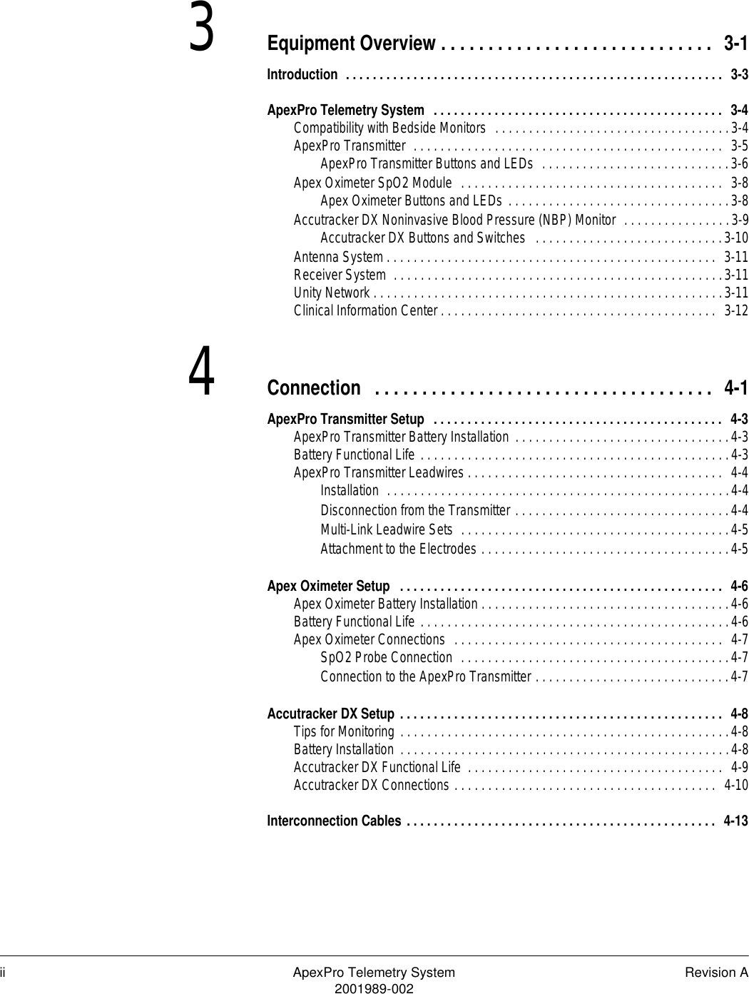
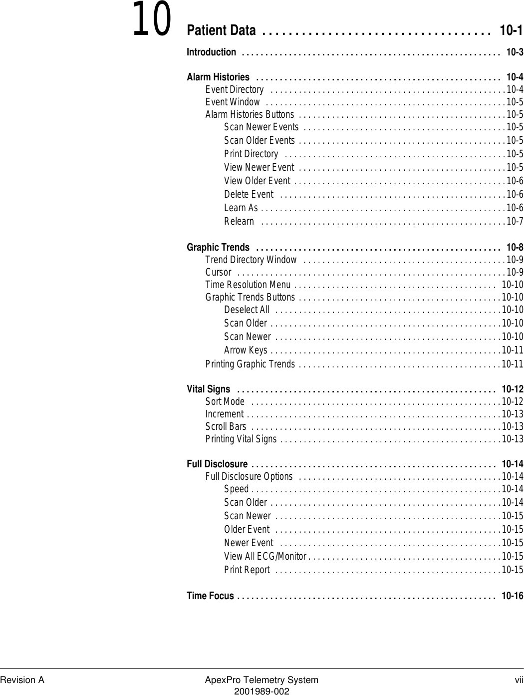
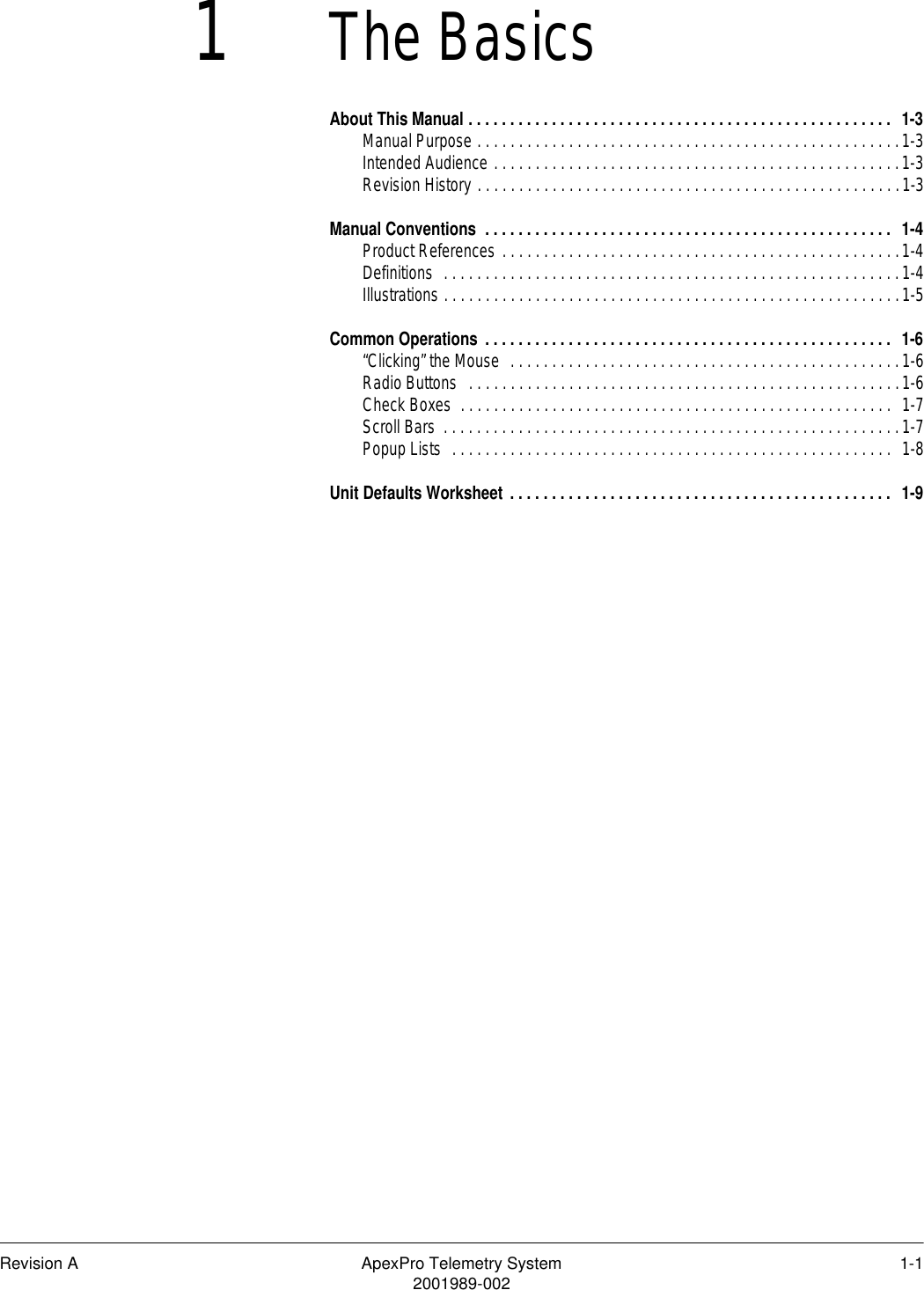


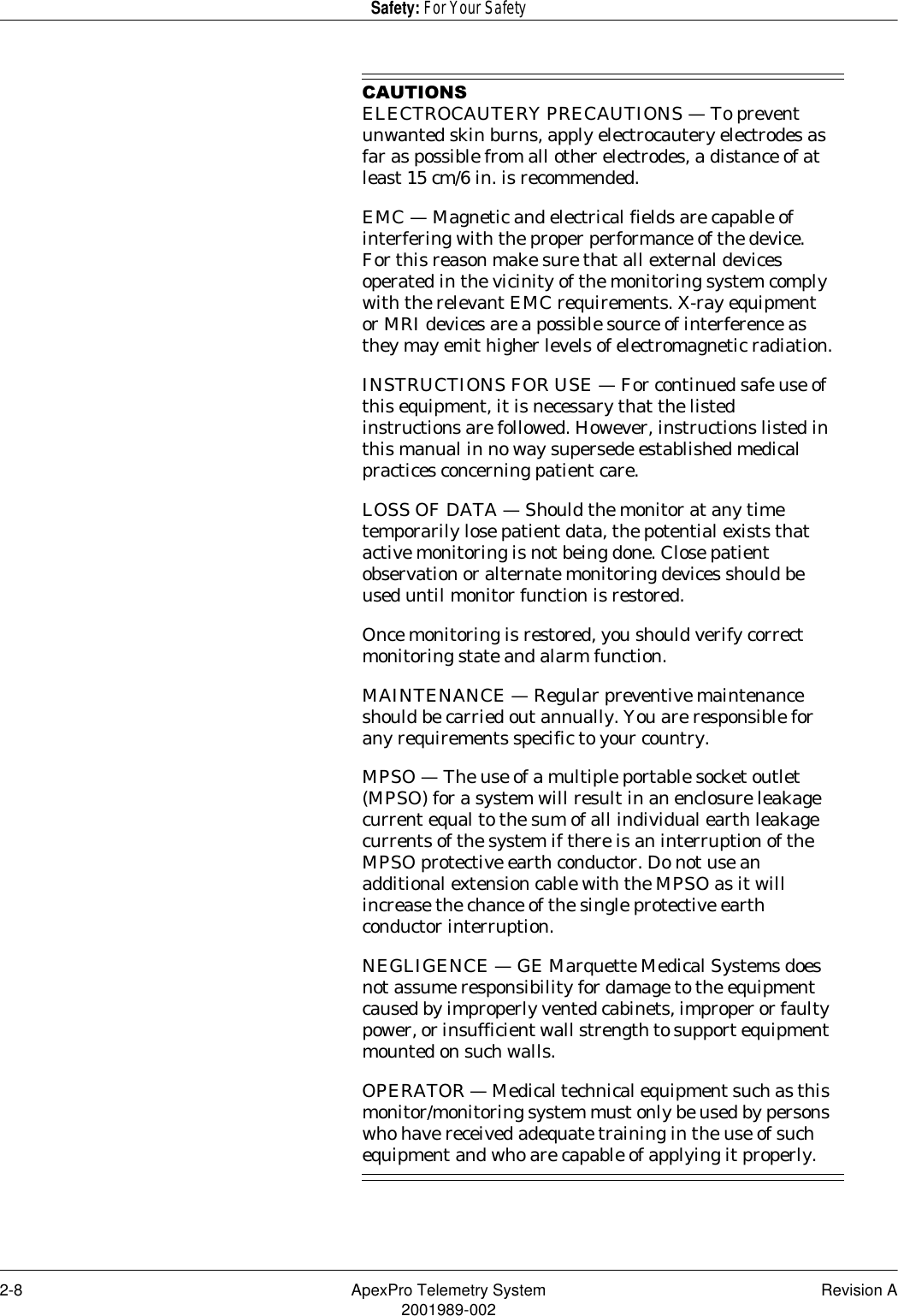
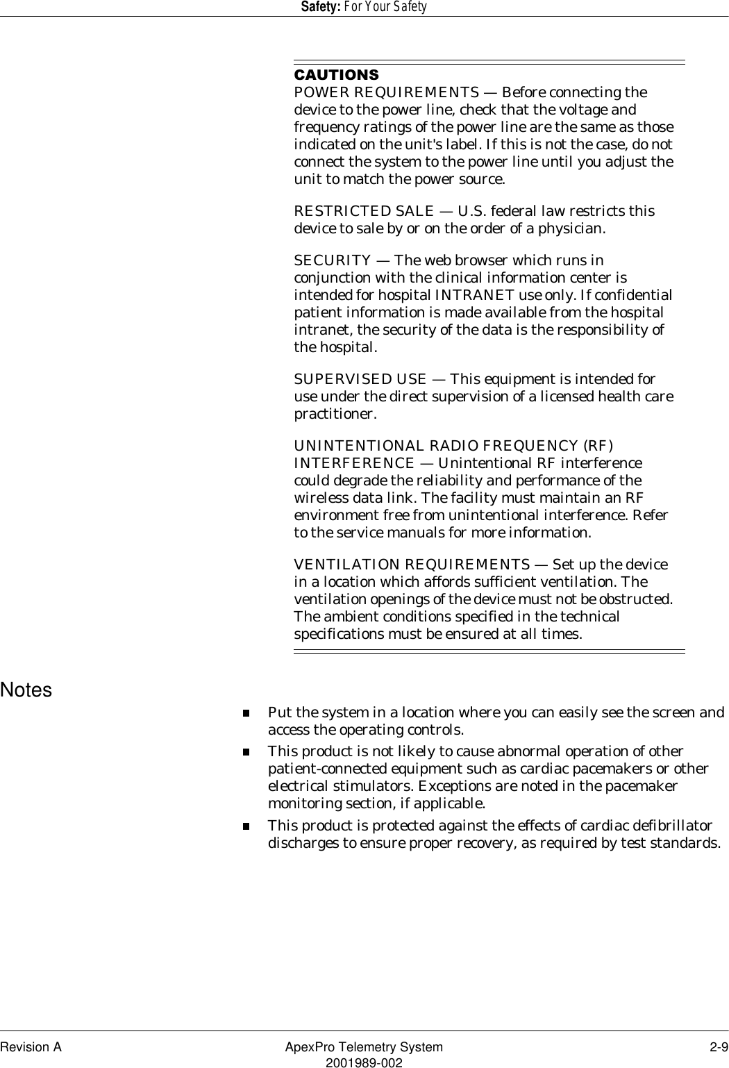
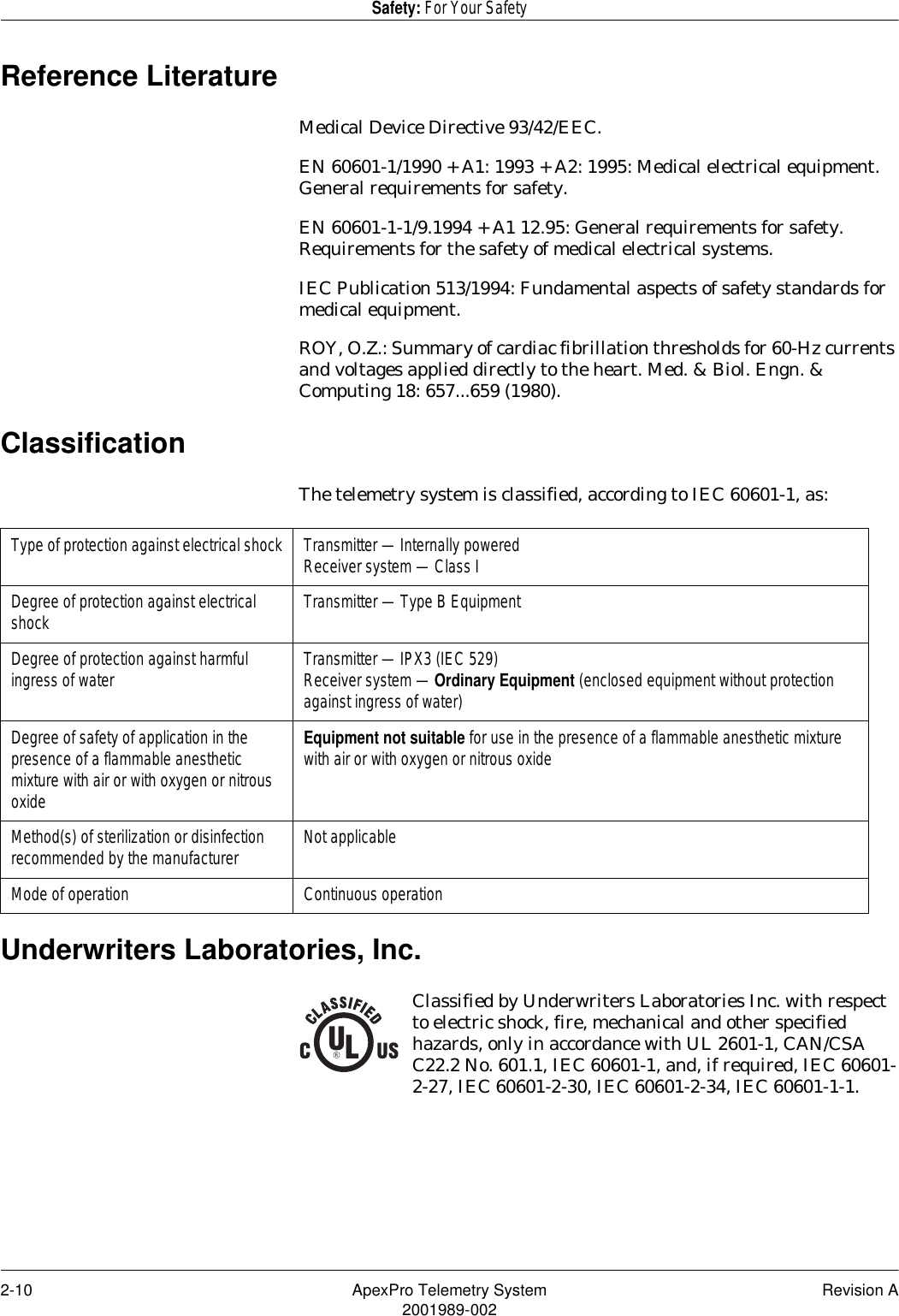
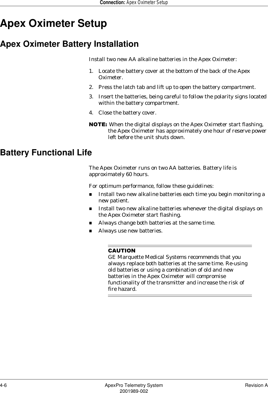
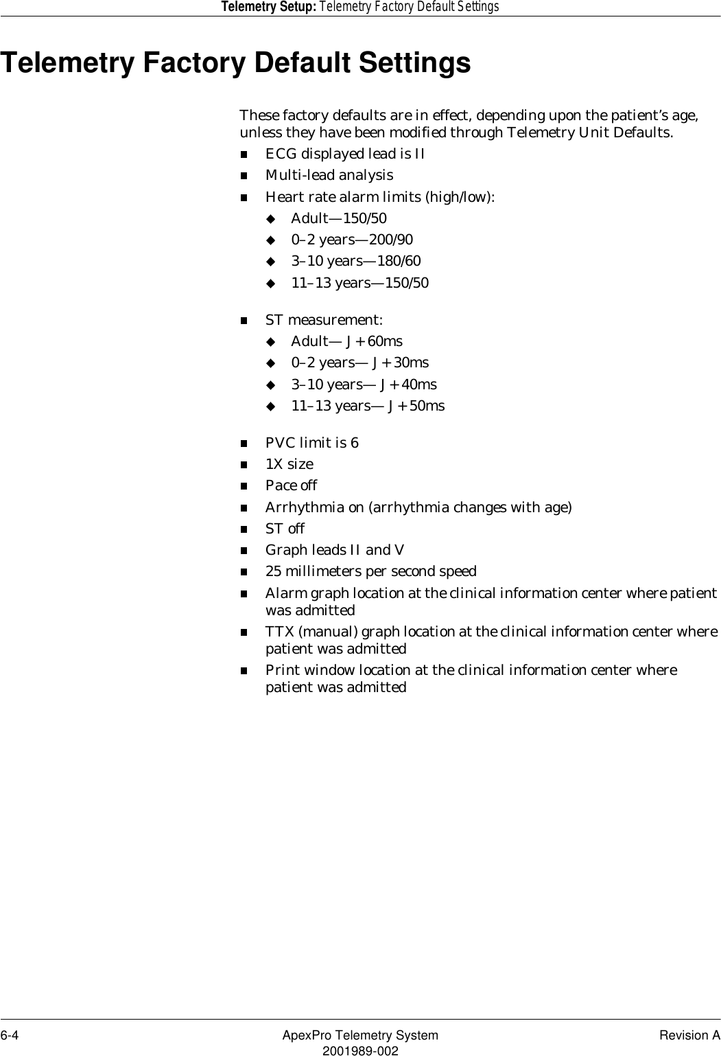
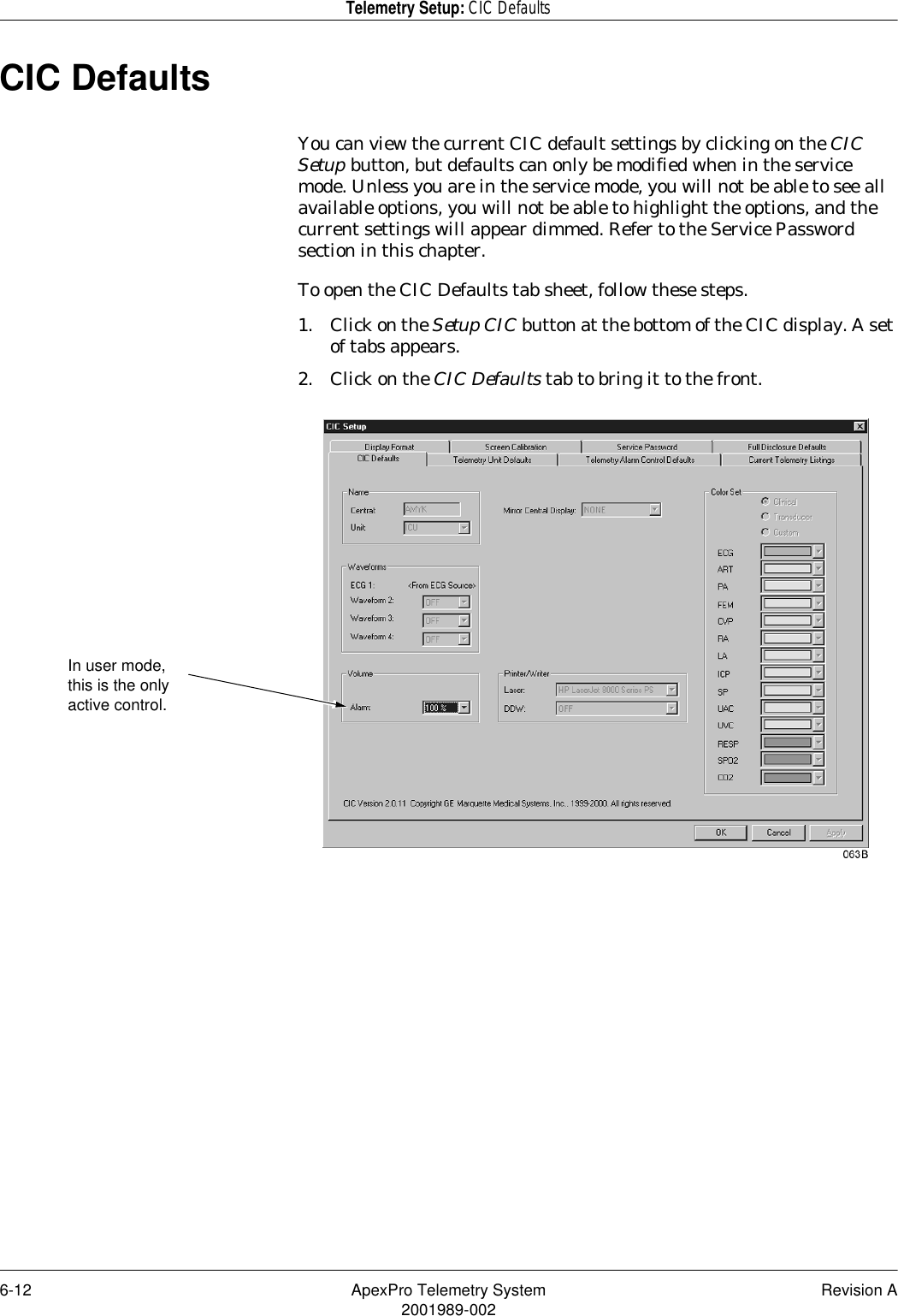
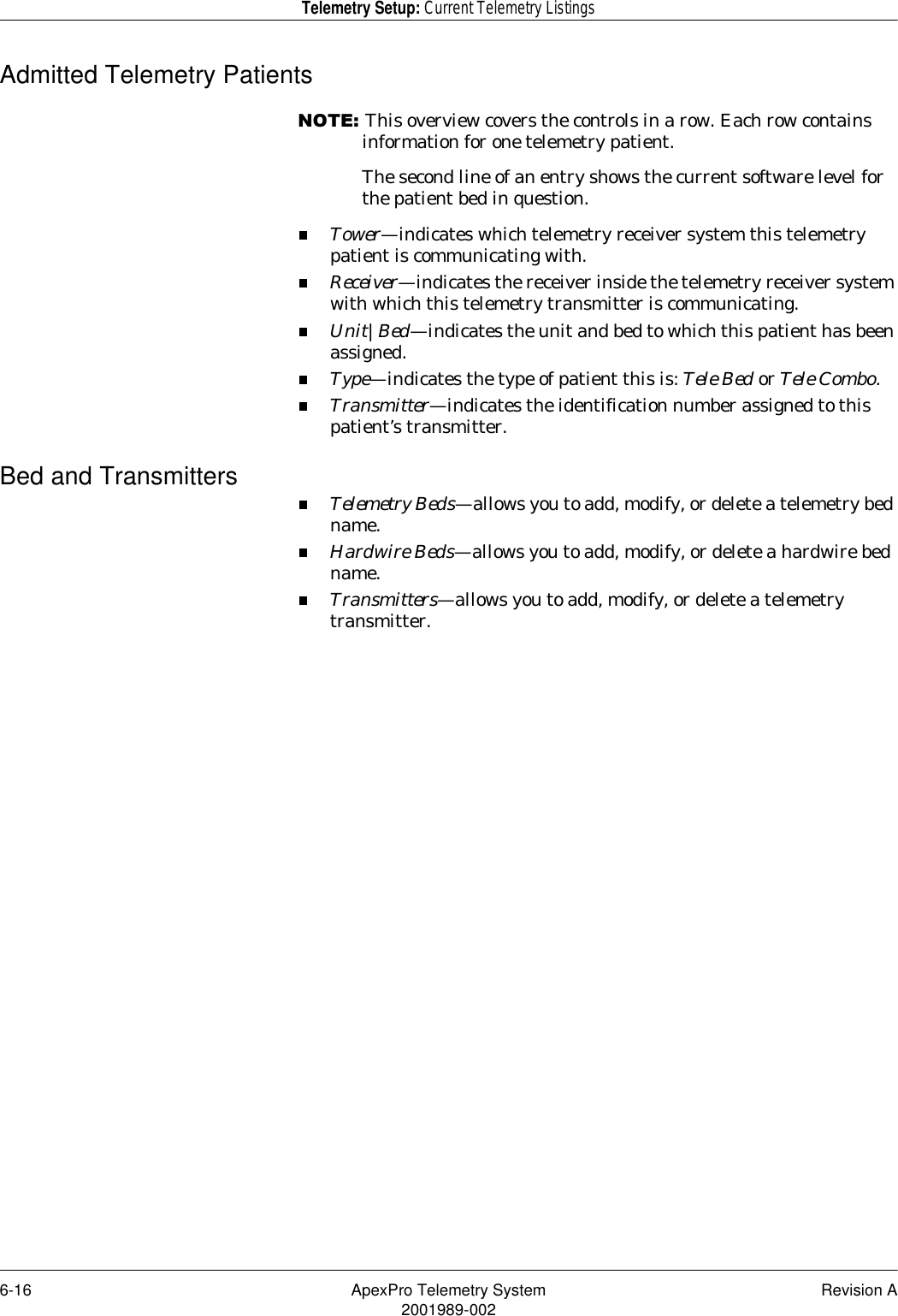
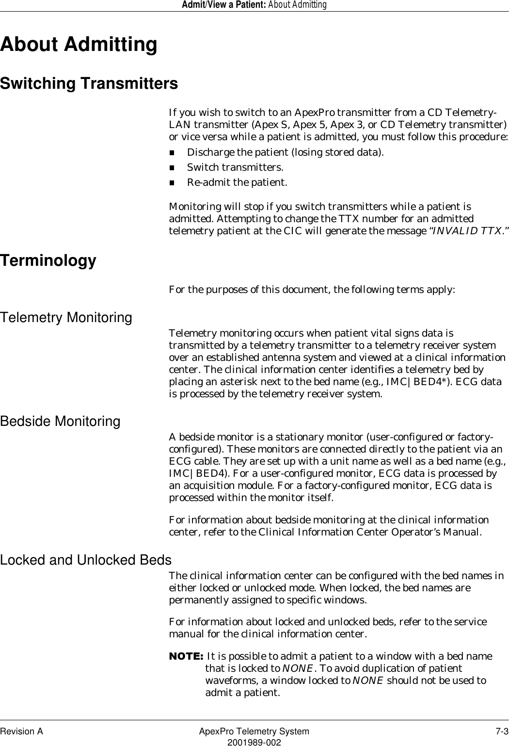
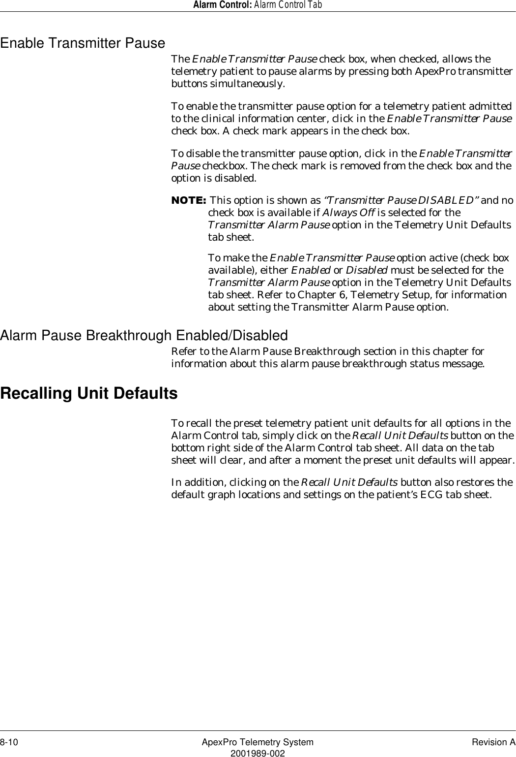
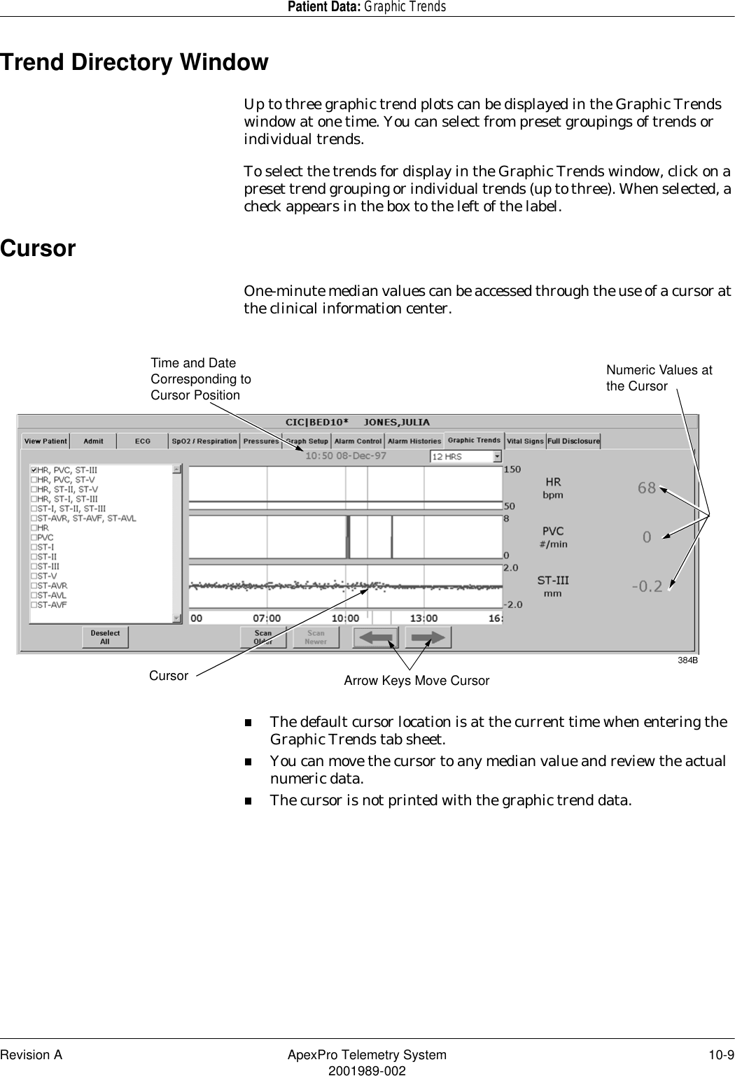
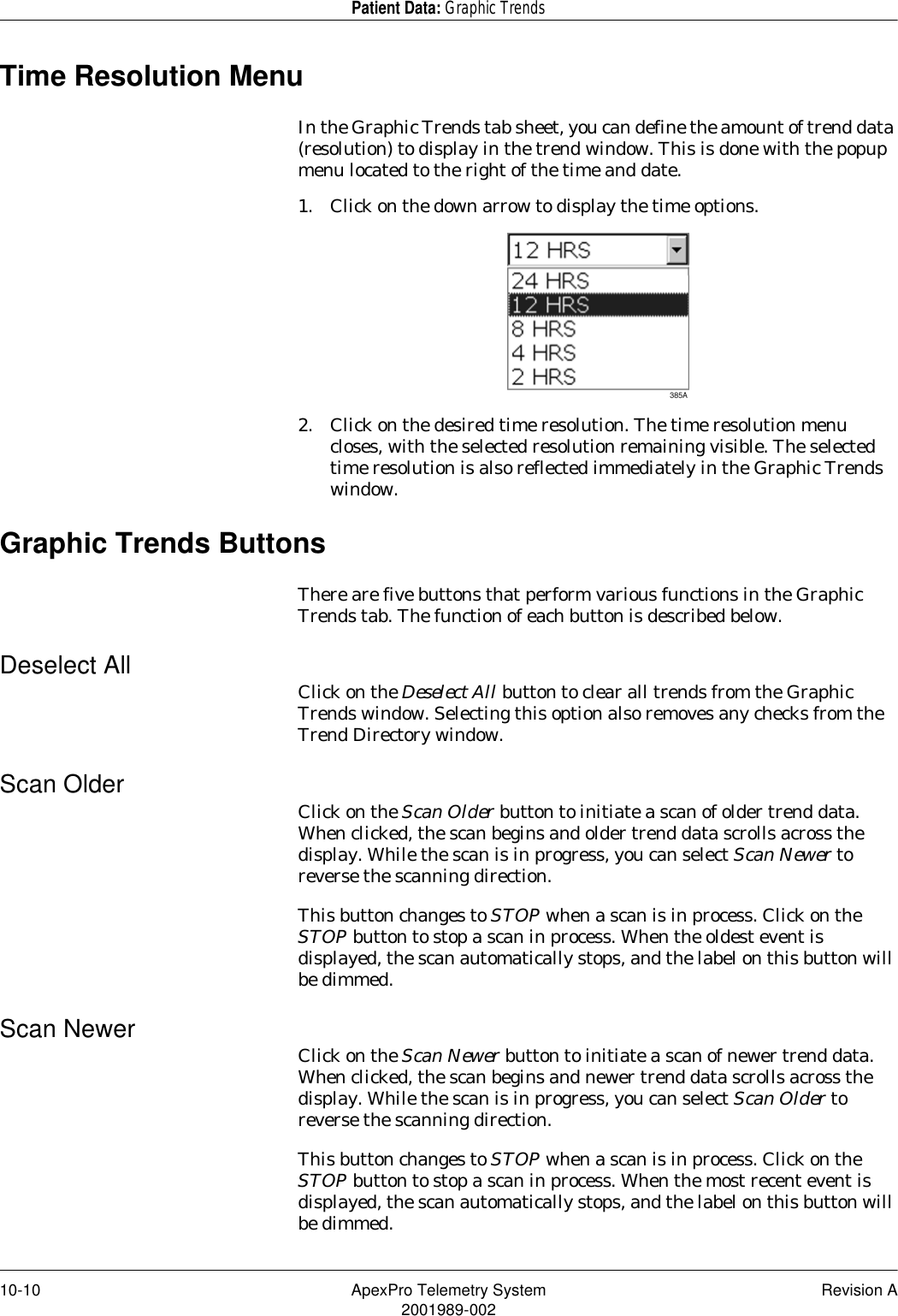
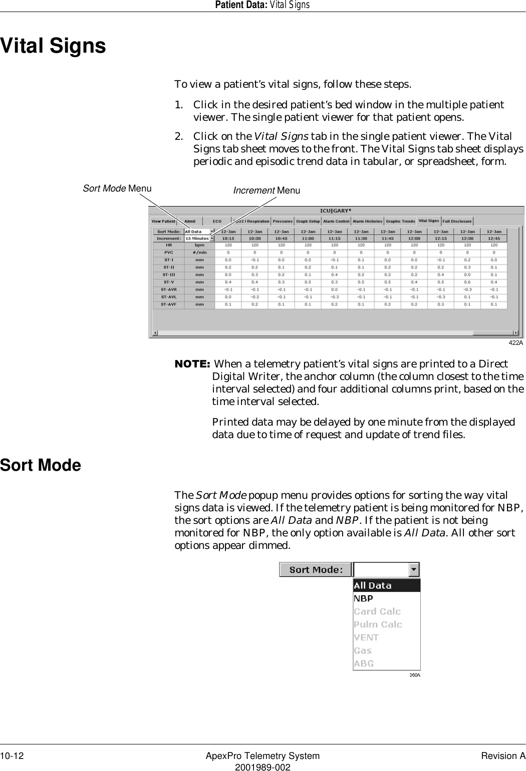
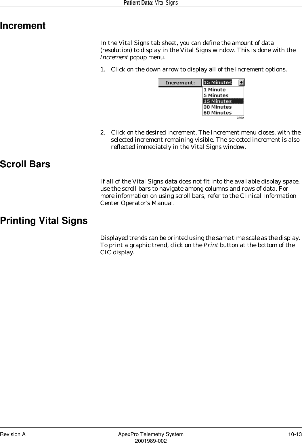
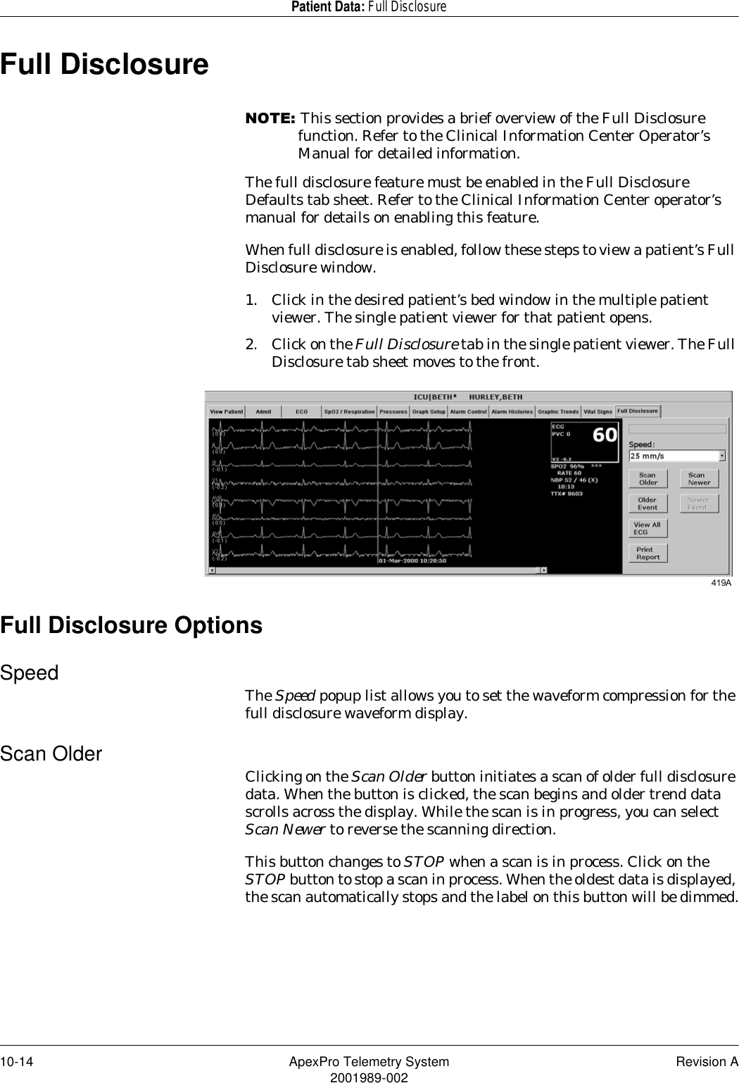
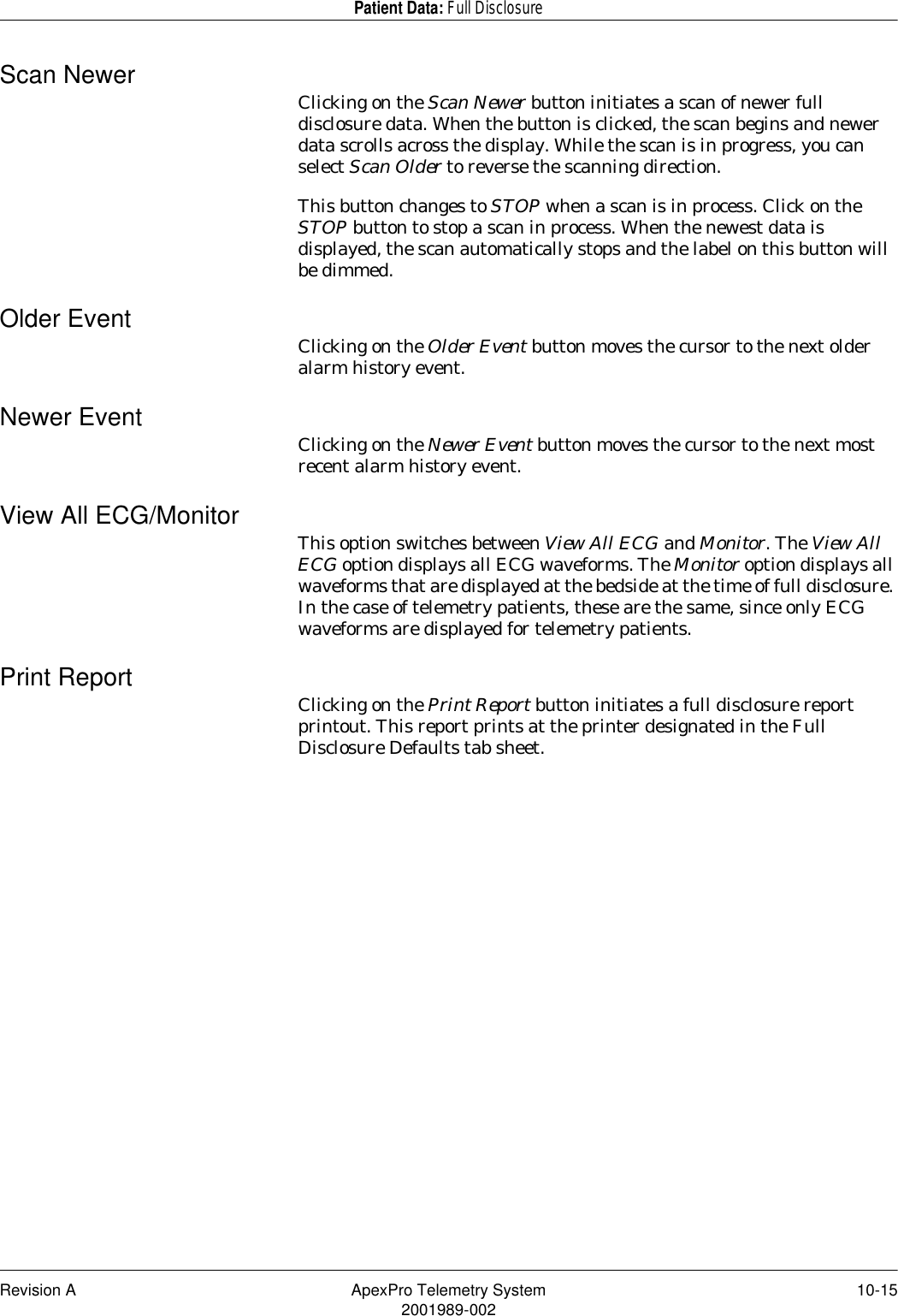
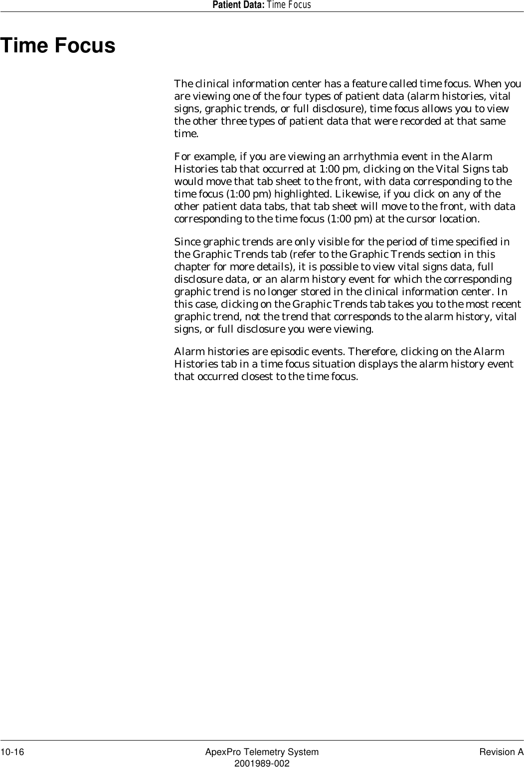
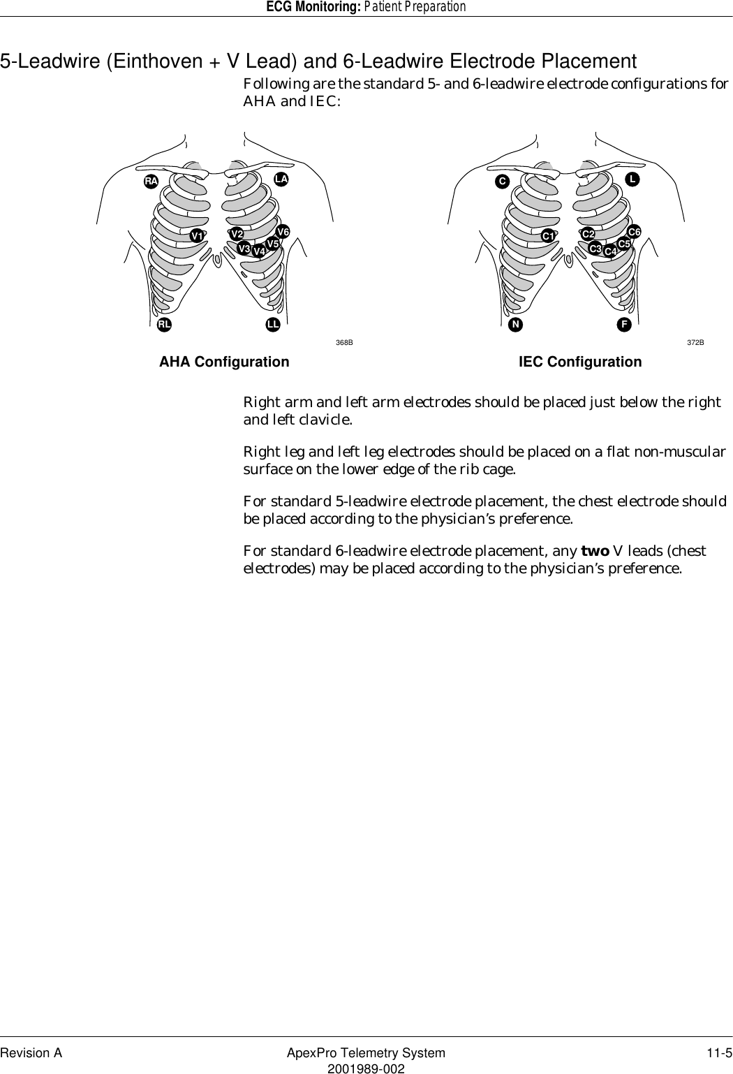
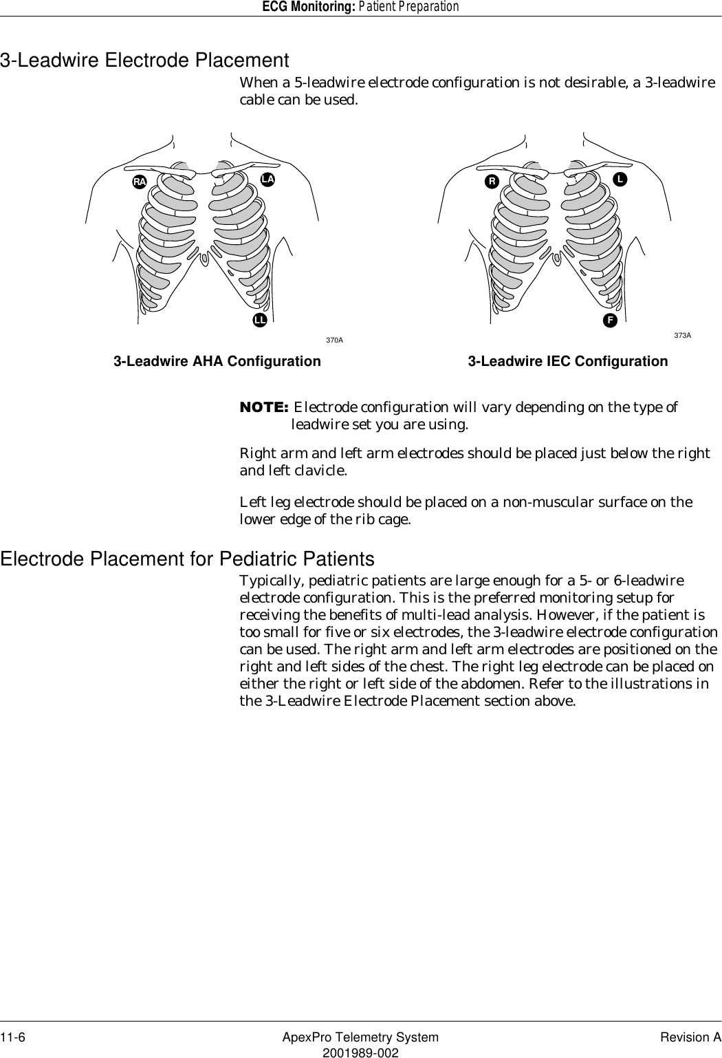
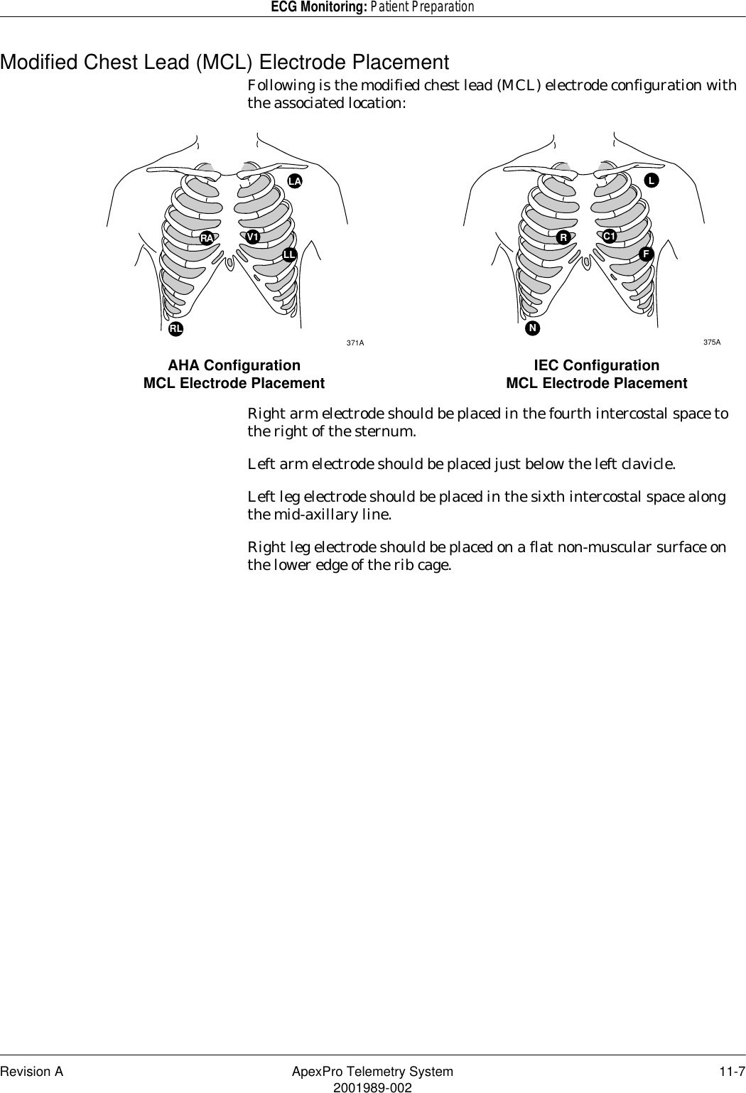
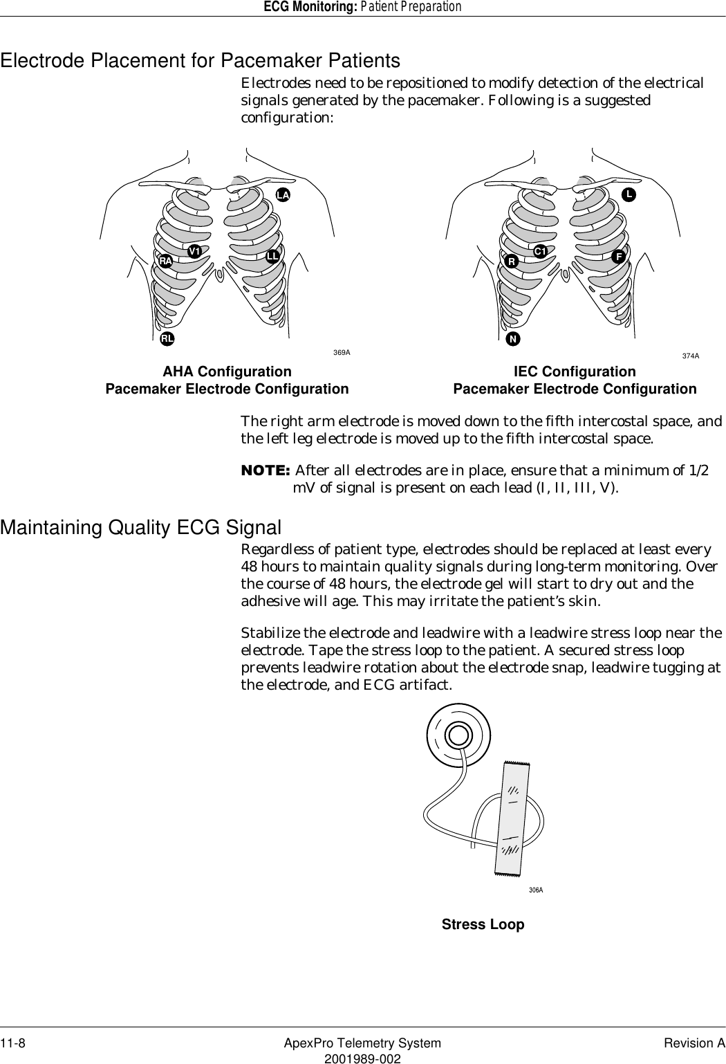
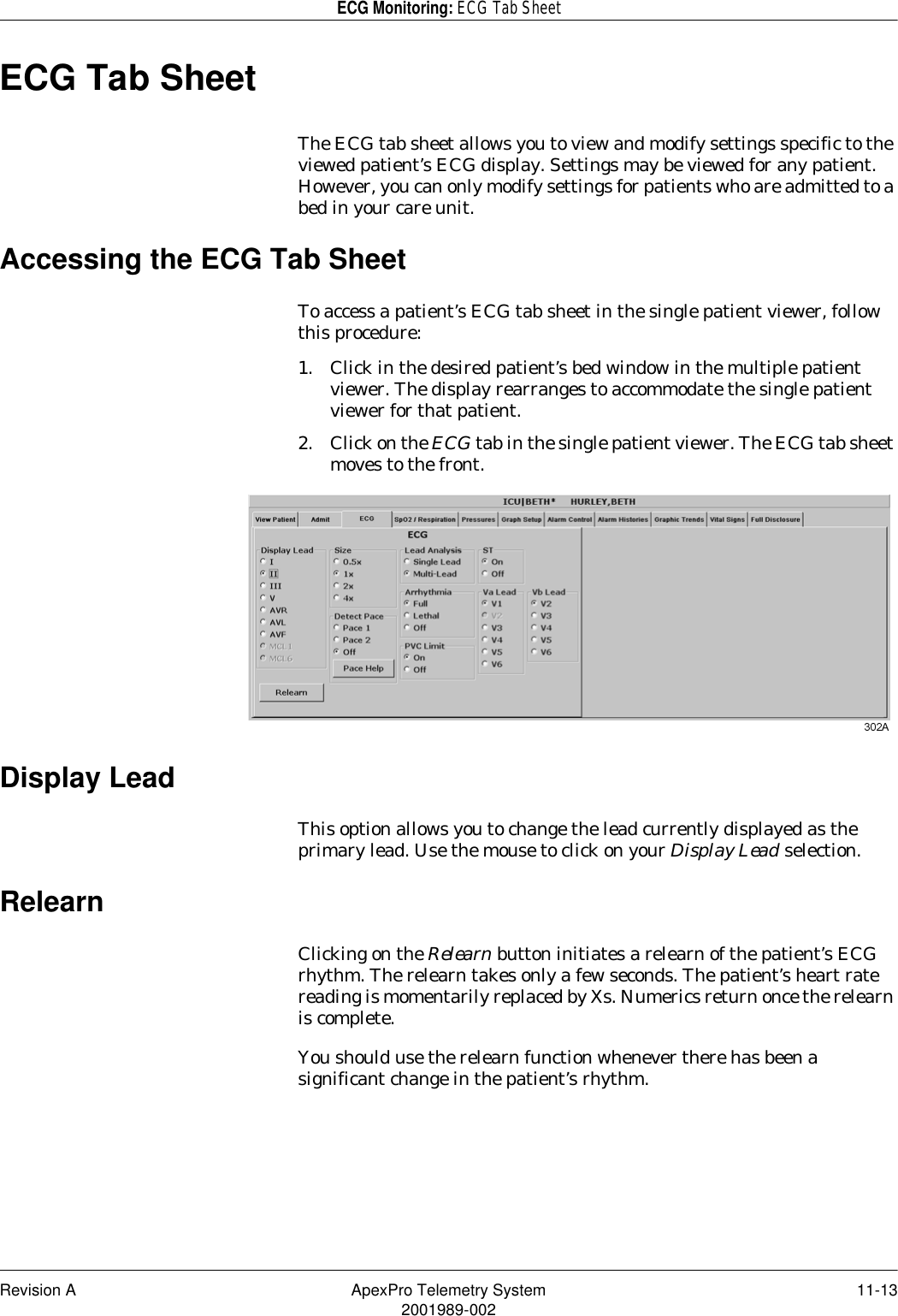
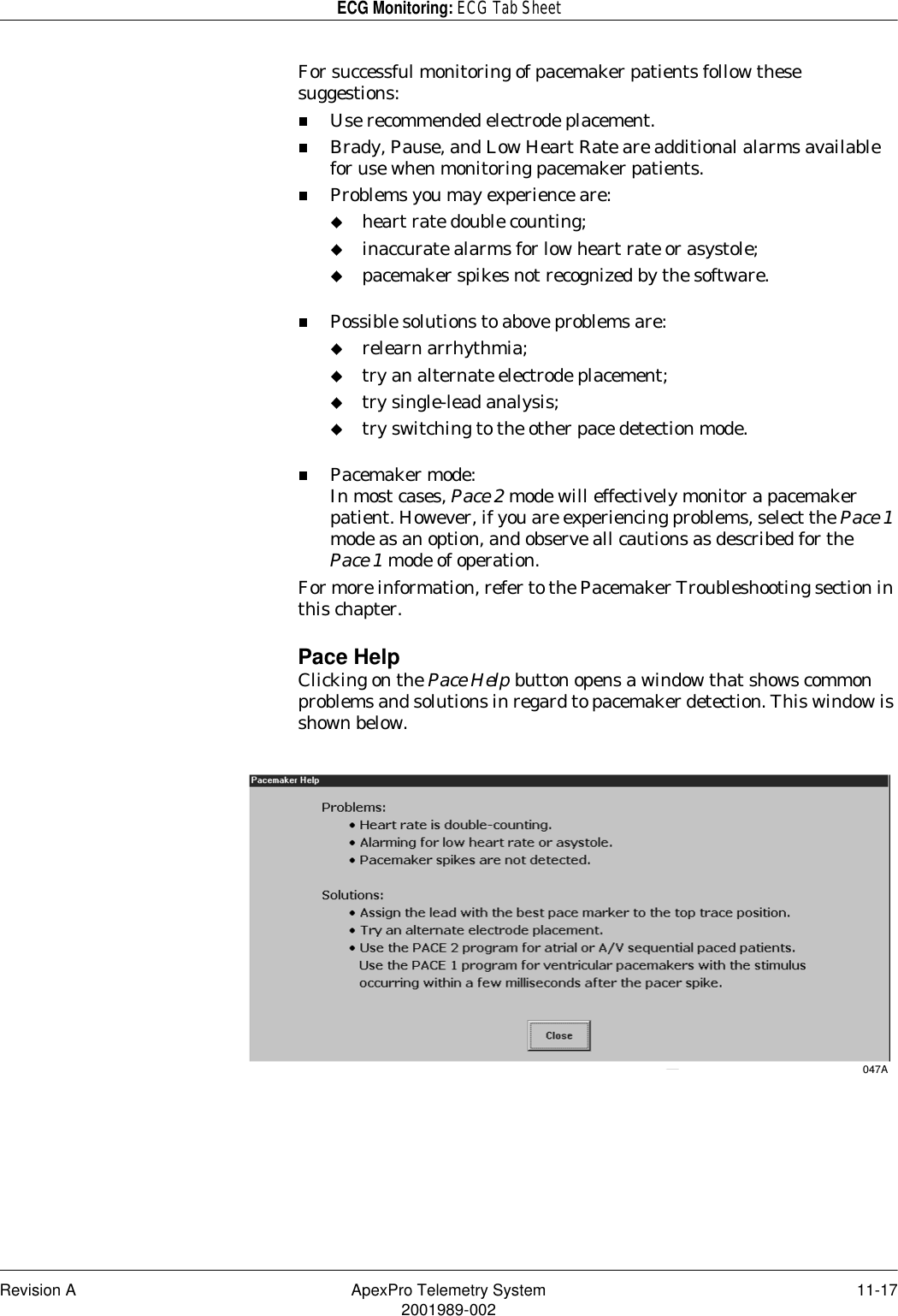
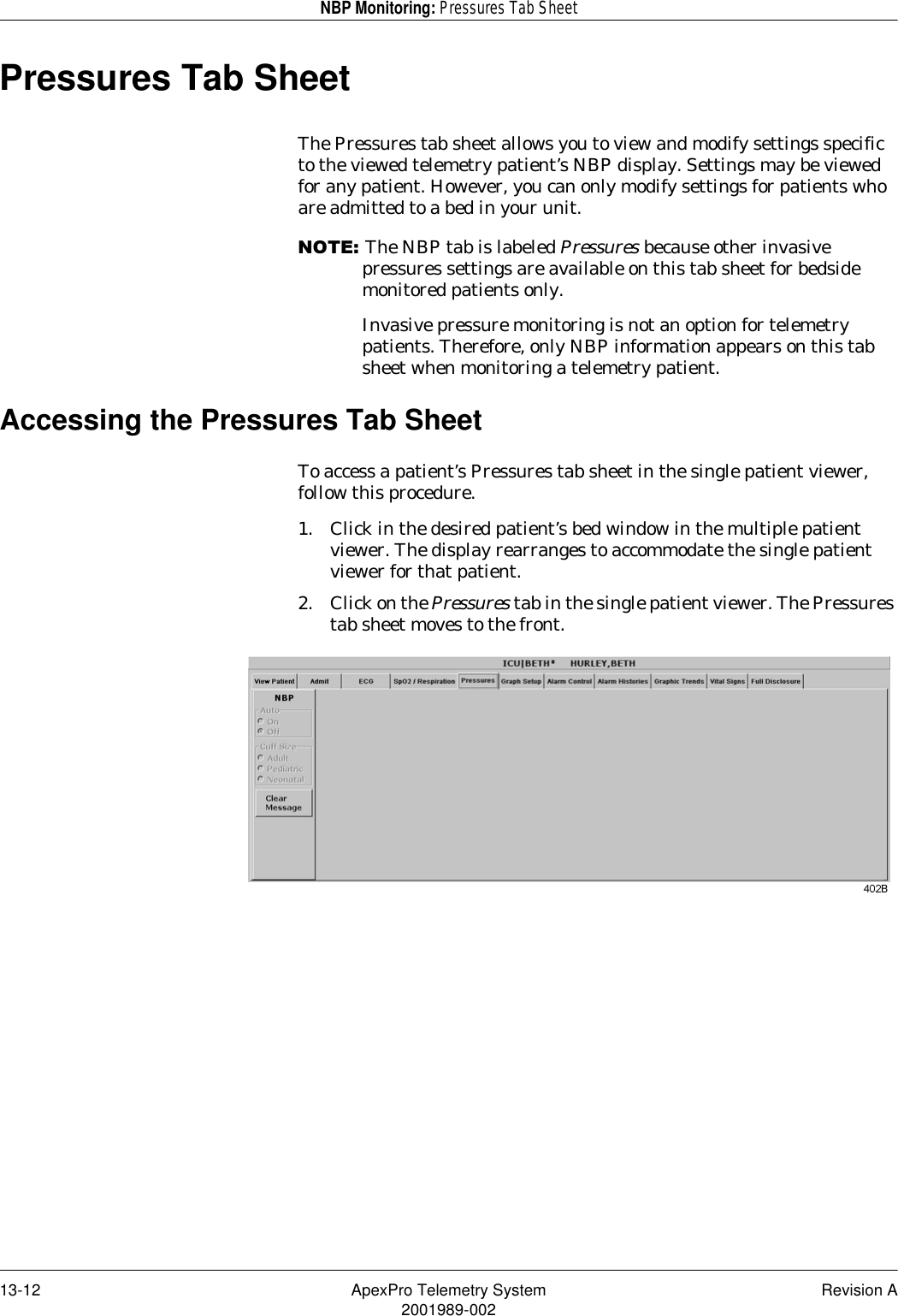
![Revision A ApexPro Telemetry System 2-112001989-002Safety: For Your SafetyEquipment Symbols127(Some symbols may not appear on all equipment.ATTENTION: Consult accompanying documents.CAUTION: To reduce the risk of electric shock, do NOT remove cover. Refer servicing to qualified service personnel.127(The rating of protection against electric shock (indicated by symbol for CF or BF) is achieved only when used with patient applied parts recommended by GE Marquette.TYPE CF APPLIED PART: Isolated (floating) applied part suitable for intentional external and internal application to the patient including direct cardiac application. “Paddles” outside the box indicate the applied part is defibrillator proof.[Medical Standard Definition:] F-type applied part (floating/isolated) complying with the specified requirements of IEC 60601-1/UL 2601-1/CSA 601.1 Medical Standards to provide a higher degree of protection against electric shock than that provided by type BF applied parts.TYPE BF APPLIED PART: Isolated (floating) applied part suitable for intentional external and internal application to the patient excluding direct cardiac application. “Paddles” outside the box indicate the applied part is defibrillator proof.[Medical Standard Definition:] F-type applied part (floating/isolated) complying with the specified requirements of IEC 60601-1/UL 2601-1/CSA 601.1 Medical Standards to provide a higher degree of protection against electric shock than that provided by type B applied parts.TYPE B APPLIED PART: Non-isolated applied part suitable for intentional external and internal application to the patient excluding direct cardiac application.[Medical Standard Definition:] Applied part complying with the specified requirements of IEC 60601-1/UL 2601-1/CSA 601.1 Medical Standards to provide protection against electric shock, particularly regarding allowable leakage current.FuseEquipotentialityAlternating current (AC)Power; I = ON; O = OFFIndicates where to press to open the door on the 7160 DDW.](https://usermanual.wiki/GE-Medical-Systems-Information-Technologies/418500-APRO/User-Guide-131599-Page-35.png)