GE Medical Systems Information Technologies 418500-APRO APEXPRO WIRELESS MEDICAL TELEMETRY TRANSMITTER User Manual
GE Medical Systems Information Technologies Inc. APEXPRO WIRELESS MEDICAL TELEMETRY TRANSMITTER
Users Manual

ApexPro™
Telemetry System
Operator’s Manual
Software Version 1
2001989-002 Revision A

T-2 ApexPro Telemetry System Revision A
2001989-002 5 June 2000
127(Due to continuing product innovation, specifications in this manual are subject to change without
notice.
Trademarked names appear throughout this document. Rather than list the names and entities that own the
trademarks or insert a trademark symbol with each mention of the trademarked name, the publisher states
that it is using the names only for editorial purposes and to the benefit of the trademark owner with no
intention of improperly using that trademark.
900 SC, ACCUSKETCH, AccuVision, APEX, AQUA-KNOT, ARCHIVIST, Autoseq, BABY MAC,
C Qwik Connect, CardioServ, CardioSmart, CardioSys, CardioWindow, CASE, CD TELEMETRY, CENTRA,
CHART GUARD, CINE 35, CORO, COROLAN, COROMETRICS, Corometrics Sensor Tip, CRG PLUS,
DASH, Digistore, Digital DATAQ, E for M, EAGLE, Event-Link, FMS 101B, FMS 111, HELLIGE,
IMAGE STORE, INTELLIMOTION, IQA, LASER SXP, MAC, MAC-LAB, MACTRODE, MARQUETTE,
MARQUETTE MAC, MARQUETTE MEDICAL SYSTEMS, MARQUETTE UNITY NETWORK, MARS,
MAX, MEDITEL, MEI, MEI in the circle logo, MEMOPORT, MEMOPORT C, MINISTORE, MINNOWS,
Monarch 8000, MULTI-LINK, MULTISCRIPTOR, MUSE, MUSE CV, Neo-Trak, NEUROSCRIPT,
OnlineABG, OXYMONITOR, Pres-R-Cuff, PRESSURE-SCRIBE, QMI, QS, Quantitative Medicine,
Quantitative Sentinel, RAC RAMS, RSVP, SAM, SEER, SILVERTRACE, SOLAR, SOLARVIEW,
Spectra 400, Spectra-Overview, Spectra-Tel, ST GUARD, TRAM, TRAM-NET, TRAM-RAC, TRAMSCOPE,
TRIM KNOB, Trimline, UNION STATION, UNITY logo, UNITY NETWORK, Vari-X, Vari-X Cardiomatic,
VariCath, VARIDEX, VAS, and Vision Care Filter are trademarks of GE Marquette Medical Systems, Inc.
registered in the United States Patent and Trademark Office.
12SL, 15SL, Access, AccuSpeak, ADVANTAGE, BAM, BODYTRODE, Cardiomatic, CardioSpeak,
CD TELEMETRY®-LAN, CENTRALSCOPE, Corolation, EDIC, EK-Pro, Event-Link Cirrus,
Event-Link Cumulus, Event-Link Nimbus, HI-RES, ICMMS, IMAGE VAULT, IMPACT.wf, INTER-LEAD,
IQA, LIFEWATCH, Managed Use, MARQUETTE PRISM, MARQUETTE® RESPONDER, MENTOR,
MicroSmart, MMS, MRT, MUSE CardioWindow, NST PRO, NAUTILUS, O2SENSOR, Octanet, OMRS,
PHi-Res, Premium, Prism, QUIK CONNECT V, QUICK CONNECT, QT Guard, SMART-PAC,
SMARTLOOK, Spiral Lok, Sweetheart, UNITY, Universal, Waterfall, and Walkmom are trademarks of
GE Marquette Medical Systems, Inc.
© GE Marquette Medical Systems, Inc., 2000. All rights reserved.
GE Marquette Medical Systems, Inc.
8200 W. Tower Ave.
Milwaukee, WI 53223 USA
Tel: 414.355.5000
800.558.5120 (USA only)
Fax: 414.355.3790
GE Marquette Hellige GmbH
Postfach 60 02 65
D-79032 Freiburg
Germany
Tel: 49.761.45.43.0
Fax: 49.761.45.43.233

Revision A ApexPro Telemetry System i
2001989-002
Contents
1The Basics . . . . . . . . . . . . . . . . . . . . . . . . . . . . . . . . . . . . . 1-1
About This Manual . . . . . . . . . . . . . . . . . . . . . . . . . . . . . . . . . . . . . . . . . . . . . . . . . . . 1-3
Manual Purpose . . . . . . . . . . . . . . . . . . . . . . . . . . . . . . . . . . . . . . . . . . . . . . . . . . .1-3
Intended Audience . . . . . . . . . . . . . . . . . . . . . . . . . . . . . . . . . . . . . . . . . . . . . . . . .1-3
Revision History . . . . . . . . . . . . . . . . . . . . . . . . . . . . . . . . . . . . . . . . . . . . . . . . . . .1-3
Manual Conventions . . . . . . . . . . . . . . . . . . . . . . . . . . . . . . . . . . . . . . . . . . . . . . . . . 1-4
Product References . . . . . . . . . . . . . . . . . . . . . . . . . . . . . . . . . . . . . . . . . . . . . . . .1-4
Definitions . . . . . . . . . . . . . . . . . . . . . . . . . . . . . . . . . . . . . . . . . . . . . . . . . . . . . . .1-4
Illustrations . . . . . . . . . . . . . . . . . . . . . . . . . . . . . . . . . . . . . . . . . . . . . . . . . . . . . . .1-5
Common Operations . . . . . . . . . . . . . . . . . . . . . . . . . . . . . . . . . . . . . . . . . . . . . . . . . 1-6
“Clicking” the Mouse . . . . . . . . . . . . . . . . . . . . . . . . . . . . . . . . . . . . . . . . . . . . . . .1-6
Radio Buttons . . . . . . . . . . . . . . . . . . . . . . . . . . . . . . . . . . . . . . . . . . . . . . . . . . . .1-6
Check Boxes . . . . . . . . . . . . . . . . . . . . . . . . . . . . . . . . . . . . . . . . . . . . . . . . . . . . 1-7
Scroll Bars . . . . . . . . . . . . . . . . . . . . . . . . . . . . . . . . . . . . . . . . . . . . . . . . . . . . . . .1-7
Popup Lists . . . . . . . . . . . . . . . . . . . . . . . . . . . . . . . . . . . . . . . . . . . . . . . . . . . . . 1-8
Unit Defaults Worksheet . . . . . . . . . . . . . . . . . . . . . . . . . . . . . . . . . . . . . . . . . . . . . . 1-9
2Safety . . . . . . . . . . . . . . . . . . . . . . . . . . . . . . . . . . . . . . . . . 2-1
For Your Safety . . . . . . . . . . . . . . . . . . . . . . . . . . . . . . . . . . . . . . . . . . . . . . . . . . . . . 2-3
Intended Use . . . . . . . . . . . . . . . . . . . . . . . . . . . . . . . . . . . . . . . . . . . . . . . . . . . . .2-3
Definitions . . . . . . . . . . . . . . . . . . . . . . . . . . . . . . . . . . . . . . . . . . . . . . . . . . . . . . .2-3
System Safety . . . . . . . . . . . . . . . . . . . . . . . . . . . . . . . . . . . . . . . . . . . . . . . . . . . .2-3
Dangers . . . . . . . . . . . . . . . . . . . . . . . . . . . . . . . . . . . . . . . . . . . . . . . . . . . . .2-3
Warnings . . . . . . . . . . . . . . . . . . . . . . . . . . . . . . . . . . . . . . . . . . . . . . . . . . . .2-4
Cautions . . . . . . . . . . . . . . . . . . . . . . . . . . . . . . . . . . . . . . . . . . . . . . . . . . . . .2-7
Notes . . . . . . . . . . . . . . . . . . . . . . . . . . . . . . . . . . . . . . . . . . . . . . . . . . . . . . .2-9
Reference Literature . . . . . . . . . . . . . . . . . . . . . . . . . . . . . . . . . . . . . . . . . . . . . 2-10
Classification . . . . . . . . . . . . . . . . . . . . . . . . . . . . . . . . . . . . . . . . . . . . . . . . . . . .2-10
Underwriters Laboratories, Inc. . . . . . . . . . . . . . . . . . . . . . . . . . . . . . . . . . . . . . .2-10
Equipment Symbols . . . . . . . . . . . . . . . . . . . . . . . . . . . . . . . . . . . . . . . . . . . . . . 2-11

ii ApexPro Telemetry System Revision A
2001989-002
3Equipment Overview . . . . . . . . . . . . . . . . . . . . . . . . . . . . . 3-1
Introduction . . . . . . . . . . . . . . . . . . . . . . . . . . . . . . . . . . . . . . . . . . . . . . . . . . . . . . . . 3-3
ApexPro Telemetry System . . . . . . . . . . . . . . . . . . . . . . . . . . . . . . . . . . . . . . . . . . . 3-4
Compatibility with Bedside Monitors . . . . . . . . . . . . . . . . . . . . . . . . . . . . . . . . . . .3-4
ApexPro Transmitter . . . . . . . . . . . . . . . . . . . . . . . . . . . . . . . . . . . . . . . . . . . . . . 3-5
ApexPro Transmitter Buttons and LEDs . . . . . . . . . . . . . . . . . . . . . . . . . . . .3-6
Apex Oximeter SpO2 Module . . . . . . . . . . . . . . . . . . . . . . . . . . . . . . . . . . . . . . . 3-8
Apex Oximeter Buttons and LEDs . . . . . . . . . . . . . . . . . . . . . . . . . . . . . . . . .3-8
Accutracker DX Noninvasive Blood Pressure (NBP) Monitor . . . . . . . . . . . . . . . .3-9
Accutracker DX Buttons and Switches . . . . . . . . . . . . . . . . . . . . . . . . . . . .3-10
Antenna System . . . . . . . . . . . . . . . . . . . . . . . . . . . . . . . . . . . . . . . . . . . . . . . . . 3-11
Receiver System . . . . . . . . . . . . . . . . . . . . . . . . . . . . . . . . . . . . . . . . . . . . . . . . .3-11
Unity Network . . . . . . . . . . . . . . . . . . . . . . . . . . . . . . . . . . . . . . . . . . . . . . . . . . . .3-11
Clinical Information Center . . . . . . . . . . . . . . . . . . . . . . . . . . . . . . . . . . . . . . . . . 3-12
4Connection . . . . . . . . . . . . . . . . . . . . . . . . . . . . . . . . . . . . 4-1
ApexPro Transmitter Setup . . . . . . . . . . . . . . . . . . . . . . . . . . . . . . . . . . . . . . . . . . . 4-3
ApexPro Transmitter Battery Installation . . . . . . . . . . . . . . . . . . . . . . . . . . . . . . . .4-3
Battery Functional Life . . . . . . . . . . . . . . . . . . . . . . . . . . . . . . . . . . . . . . . . . . . . . .4-3
ApexPro Transmitter Leadwires . . . . . . . . . . . . . . . . . . . . . . . . . . . . . . . . . . . . . . 4-4
Installation . . . . . . . . . . . . . . . . . . . . . . . . . . . . . . . . . . . . . . . . . . . . . . . . . . .4-4
Disconnection from the Transmitter . . . . . . . . . . . . . . . . . . . . . . . . . . . . . . . .4-4
Multi-Link Leadwire Sets . . . . . . . . . . . . . . . . . . . . . . . . . . . . . . . . . . . . . . . .4-5
Attachment to the Electrodes . . . . . . . . . . . . . . . . . . . . . . . . . . . . . . . . . . . . .4-5
Apex Oximeter Setup . . . . . . . . . . . . . . . . . . . . . . . . . . . . . . . . . . . . . . . . . . . . . . . . 4-6
Apex Oximeter Battery Installation . . . . . . . . . . . . . . . . . . . . . . . . . . . . . . . . . . . . .4-6
Battery Functional Life . . . . . . . . . . . . . . . . . . . . . . . . . . . . . . . . . . . . . . . . . . . . . .4-6
Apex Oximeter Connections . . . . . . . . . . . . . . . . . . . . . . . . . . . . . . . . . . . . . . . . 4-7
SpO2 Probe Connection . . . . . . . . . . . . . . . . . . . . . . . . . . . . . . . . . . . . . . . .4-7
Connection to the ApexPro Transmitter . . . . . . . . . . . . . . . . . . . . . . . . . . . . .4-7
Accutracker DX Setup . . . . . . . . . . . . . . . . . . . . . . . . . . . . . . . . . . . . . . . . . . . . . . . . 4-8
Tips for Monitoring . . . . . . . . . . . . . . . . . . . . . . . . . . . . . . . . . . . . . . . . . . . . . . . . .4-8
Battery Installation . . . . . . . . . . . . . . . . . . . . . . . . . . . . . . . . . . . . . . . . . . . . . . . . .4-8
Accutracker DX Functional Life . . . . . . . . . . . . . . . . . . . . . . . . . . . . . . . . . . . . . . 4-9
Accutracker DX Connections . . . . . . . . . . . . . . . . . . . . . . . . . . . . . . . . . . . . . . . 4-10
Interconnection Cables . . . . . . . . . . . . . . . . . . . . . . . . . . . . . . . . . . . . . . . . . . . . . . 4-13

Revision A ApexPro Telemetry System iii
2001989-002
5Maintenance . . . . . . . . . . . . . . . . . . . . . . . . . . . . . . . . . . . 5-1
Biocompatibility . . . . . . . . . . . . . . . . . . . . . . . . . . . . . . . . . . . . . . . . . . . . . . . . . . . . . 5-3
Inspection . . . . . . . . . . . . . . . . . . . . . . . . . . . . . . . . . . . . . . . . . . . . . . . . . . . . . . . . . . 5-4
General Cleaning . . . . . . . . . . . . . . . . . . . . . . . . . . . . . . . . . . . . . . . . . . . . . . . . . . . . 5-5
Cleaning the Transmitters . . . . . . . . . . . . . . . . . . . . . . . . . . . . . . . . . . . . . . . . . . . . . 5-6
Cleaning the Leadwires . . . . . . . . . . . . . . . . . . . . . . . . . . . . . . . . . . . . . . . . . . . . . . . 5-7
Cleaning the Power Unit . . . . . . . . . . . . . . . . . . . . . . . . . . . . . . . . . . . . . . . . . . . . . . 5-8
Transmitter and Leadwire Storage . . . . . . . . . . . . . . . . . . . . . . . . . . . . . . . . . . . . . . 5-9
Transmitter Holder . . . . . . . . . . . . . . . . . . . . . . . . . . . . . . . . . . . . . . . . . . . . . . . . .5-9
Storage Guidelines . . . . . . . . . . . . . . . . . . . . . . . . . . . . . . . . . . . . . . . . . . . . . . . .5-9
Technical Maintenance . . . . . . . . . . . . . . . . . . . . . . . . . . . . . . . . . . . . . . . . . . . . . . 5-10
6Telemetry Setup . . . . . . . . . . . . . . . . . . . . . . . . . . . . . . . . 6-1
Introduction . . . . . . . . . . . . . . . . . . . . . . . . . . . . . . . . . . . . . . . . . . . . . . . . . . . . . . . . 6-3
Telemetry Factory Default Settings . . . . . . . . . . . . . . . . . . . . . . . . . . . . . . . . . . . . . 6-4
Service Password . . . . . . . . . . . . . . . . . . . . . . . . . . . . . . . . . . . . . . . . . . . . . . . . . . . 6-5
Telemetry Unit Defaults . . . . . . . . . . . . . . . . . . . . . . . . . . . . . . . . . . . . . . . . . . . . . . . 6-6
Viewing Telemetry Unit Defaults . . . . . . . . . . . . . . . . . . . . . . . . . . . . . . . . . . . . . .6-6
Graph Setup . . . . . . . . . . . . . . . . . . . . . . . . . . . . . . . . . . . . . . . . . . . . . . . . . .6-7
Waveforms . . . . . . . . . . . . . . . . . . . . . . . . . . . . . . . . . . . . . . . . . . . . . . . . . . .6-7
Transmitter Graph . . . . . . . . . . . . . . . . . . . . . . . . . . . . . . . . . . . . . . . . . . . . .6-8
Alarm Graph . . . . . . . . . . . . . . . . . . . . . . . . . . . . . . . . . . . . . . . . . . . . . . . . . .6-8
Display Lead . . . . . . . . . . . . . . . . . . . . . . . . . . . . . . . . . . . . . . . . . . . . . . . . .6-8
Arrhythmia . . . . . . . . . . . . . . . . . . . . . . . . . . . . . . . . . . . . . . . . . . . . . . . . . . .6-8
Lead Analysis . . . . . . . . . . . . . . . . . . . . . . . . . . . . . . . . . . . . . . . . . . . . . . . . .6-8
ST Analysis . . . . . . . . . . . . . . . . . . . . . . . . . . . . . . . . . . . . . . . . . . . . . . . . . .6-9
Va and Vb Lead . . . . . . . . . . . . . . . . . . . . . . . . . . . . . . . . . . . . . . . . . . . . . . .6-9
Detect Pace . . . . . . . . . . . . . . . . . . . . . . . . . . . . . . . . . . . . . . . . . . . . . . . . . .6-9
Patient Data Transfer . . . . . . . . . . . . . . . . . . . . . . . . . . . . . . . . . . . . . . . . . . .6-9
Patient Age . . . . . . . . . . . . . . . . . . . . . . . . . . . . . . . . . . . . . . . . . . . . . . . . .6-10
Transmitter Alarm Pause . . . . . . . . . . . . . . . . . . . . . . . . . . . . . . . . . . . . . . .6-11
Alarm Pause Breakthrough . . . . . . . . . . . . . . . . . . . . . . . . . . . . . . . . . . . . .6-11

iv ApexPro Telemetry System Revision A
2001989-002
CIC Defaults . . . . . . . . . . . . . . . . . . . . . . . . . . . . . . . . . . . . . . . . . . . . . . . . . . . . . . . 6-12
Adjusting Alarm Volume . . . . . . . . . . . . . . . . . . . . . . . . . . . . . . . . . . . . . . . . . . . 6-14
Current Telemetry Listings . . . . . . . . . . . . . . . . . . . . . . . . . . . . . . . . . . . . . . . . . . . 6-15
Admitted Telemetry Patients . . . . . . . . . . . . . . . . . . . . . . . . . . . . . . . . . . . .6-16
Bed and Transmitters . . . . . . . . . . . . . . . . . . . . . . . . . . . . . . . . . . . . . . . . . .6-16
Full Disclosure Defaults . . . . . . . . . . . . . . . . . . . . . . . . . . . . . . . . . . . . . . . . . . . . . 6-17
7Admit/View a Patient . . . . . . . . . . . . . . . . . . . . . . . . . . . . . 7-1
About Admitting . . . . . . . . . . . . . . . . . . . . . . . . . . . . . . . . . . . . . . . . . . . . . . . . . . . . . 7-3
Switching Transmitters . . . . . . . . . . . . . . . . . . . . . . . . . . . . . . . . . . . . . . . . . . . . . .7-3
Terminology . . . . . . . . . . . . . . . . . . . . . . . . . . . . . . . . . . . . . . . . . . . . . . . . . . . . . .7-3
Telemetry Monitoring . . . . . . . . . . . . . . . . . . . . . . . . . . . . . . . . . . . . . . . . . . .7-3
Bedside Monitoring . . . . . . . . . . . . . . . . . . . . . . . . . . . . . . . . . . . . . . . . . . . .7-3
Locked and Unlocked Beds . . . . . . . . . . . . . . . . . . . . . . . . . . . . . . . . . . . . . .7-3
Admit Instructions . . . . . . . . . . . . . . . . . . . . . . . . . . . . . . . . . . . . . . . . . . . . . . . . . . . 7-4
Admit Procedure . . . . . . . . . . . . . . . . . . . . . . . . . . . . . . . . . . . . . . . . . . . . . . . . . .7-4
Discharge Instructions . . . . . . . . . . . . . . . . . . . . . . . . . . . . . . . . . . . . . . . . . . . . . . . 7-7
Clearing a Patient Window . . . . . . . . . . . . . . . . . . . . . . . . . . . . . . . . . . . . . . . . . . 7-8
Viewing a Patient . . . . . . . . . . . . . . . . . . . . . . . . . . . . . . . . . . . . . . . . . . . . . . . . . . . . 7-9
Sample . . . . . . . . . . . . . . . . . . . . . . . . . . . . . . . . . . . . . . . . . . . . . . . . . . . . . . . . . .7-9
Relearn . . . . . . . . . . . . . . . . . . . . . . . . . . . . . . . . . . . . . . . . . . . . . . . . . . . . . . . . .7-9
Viewing Another Patient . . . . . . . . . . . . . . . . . . . . . . . . . . . . . . . . . . . . . . . . . . . . . 7-10
Viewing in the Single Patient Viewer . . . . . . . . . . . . . . . . . . . . . . . . . . . . . . . . . .7-10
Viewing in the Multiple Patient Viewer . . . . . . . . . . . . . . . . . . . . . . . . . . . . . . . . 7-11
Alarm Condition Indicators . . . . . . . . . . . . . . . . . . . . . . . . . . . . . . . . . . . . . . . . . . . 7-13

Revision A ApexPro Telemetry System v
2001989-002
8Alarm Control . . . . . . . . . . . . . . . . . . . . . . . . . . . . . . . . . . 8-1
Alarm Structure . . . . . . . . . . . . . . . . . . . . . . . . . . . . . . . . . . . . . . . . . . . . . . . . . . . . . 8-3
Patient Status Alarms . . . . . . . . . . . . . . . . . . . . . . . . . . . . . . . . . . . . . . . . . . . . . .8-3
Colored Window Borders . . . . . . . . . . . . . . . . . . . . . . . . . . . . . . . . . . . . . . . .8-4
Automatic Alarm Graphs . . . . . . . . . . . . . . . . . . . . . . . . . . . . . . . . . . . . . . . .8-4
System Status Alarms . . . . . . . . . . . . . . . . . . . . . . . . . . . . . . . . . . . . . . . . . . . . . .8-4
Alarm Control Tab . . . . . . . . . . . . . . . . . . . . . . . . . . . . . . . . . . . . . . . . . . . . . . . . . . . 8-5
Accessing the Alarm Control Tab . . . . . . . . . . . . . . . . . . . . . . . . . . . . . . . . . . . . .8-5
Parameter Limits . . . . . . . . . . . . . . . . . . . . . . . . . . . . . . . . . . . . . . . . . . . . . . . . . 8-6
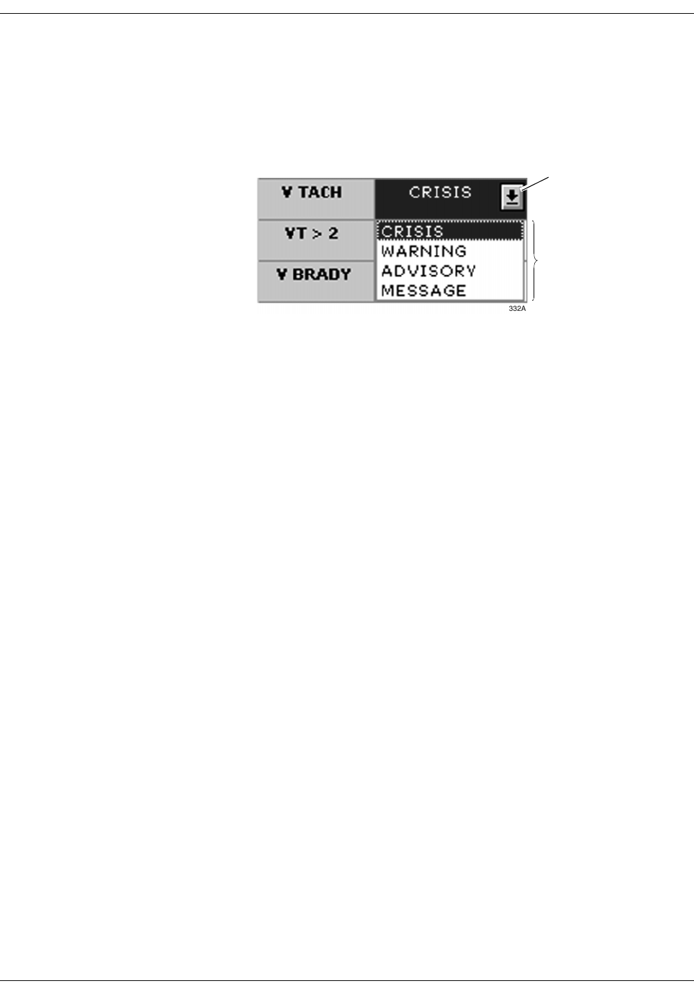
Parameter Alarm Levels . . . . . . . . . . . . . . . . . . . . . . . . . . . . . . . . . . . . . . . . . . . .8-6
Arrhythmia Alarm Levels . . . . . . . . . . . . . . . . . . . . . . . . . . . . . . . . . . . . . . . . . . . 8-7
Alarms On/Off . . . . . . . . . . . . . . . . . . . . . . . . . . . . . . . . . . . . . . . . . . . . . . . . . . . 8-8
Alarm Off Reason . . . . . . . . . . . . . . . . . . . . . . . . . . . . . . . . . . . . . . . . . . . . . .8-9
Enable Transmitter Pause . . . . . . . . . . . . . . . . . . . . . . . . . . . . . . . . . . . . . .8-10
Alarm Pause Breakthrough Enabled/Disabled . . . . . . . . . . . . . . . . . . . . . . .8-10
Recalling Unit Defaults . . . . . . . . . . . . . . . . . . . . . . . . . . . . . . . . . . . . . . . . . . . . .8-10
Alarm Help . . . . . . . . . . . . . . . . . . . . . . . . . . . . . . . . . . . . . . . . . . . . . . . . . . . . . 8-11
Printing Alarm Settings . . . . . . . . . . . . . . . . . . . . . . . . . . . . . . . . . . . . . . . . . . . .8-11
Alarm Pause Breakthrough . . . . . . . . . . . . . . . . . . . . . . . . . . . . . . . . . . . . . . . . . . . 8-12
Factory Alarm Default Settings . . . . . . . . . . . . . . . . . . . . . . . . . . . . . . . . . . . . . . . 8-14
Patient Status Alarms . . . . . . . . . . . . . . . . . . . . . . . . . . . . . . . . . . . . . . . . . . . . .8-14
Crisis Alarms . . . . . . . . . . . . . . . . . . . . . . . . . . . . . . . . . . . . . . . . . . . . . . . .8-14
Warning Alarms . . . . . . . . . . . . . . . . . . . . . . . . . . . . . . . . . . . . . . . . . . . . . .8-14
System Status Alarms . . . . . . . . . . . . . . . . . . . . . . . . . . . . . . . . . . . . . . . . . . . . 8-15
System Warning Alarms . . . . . . . . . . . . . . . . . . . . . . . . . . . . . . . . . . . . . . . .8-15
System Advisory Alarms . . . . . . . . . . . . . . . . . . . . . . . . . . . . . . . . . . . . . . .8-15
Unit Default Settings for Alarms . . . . . . . . . . . . . . . . . . . . . . . . . . . . . . . . . . . . . . . 8-16
Telemetry Alarm Control Defaults . . . . . . . . . . . . . . . . . . . . . . . . . . . . . . . . . . . .8-16
Parameter Limits . . . . . . . . . . . . . . . . . . . . . . . . . . . . . . . . . . . . . . . . . . . . .8-17
Parameter Alarm Levels . . . . . . . . . . . . . . . . . . . . . . . . . . . . . . . . . . . . . . . .8-18
Arrhythmia Alarm Levels . . . . . . . . . . . . . . . . . . . . . . . . . . . . . . . . . . . . . . .8-19

vi ApexPro Telemetry System Revision A
2001989-002
9Printing . . . . . . . . . . . . . . . . . . . . . . . . . . . . . . . . . . . . . . . . 9-1
Initiating a Graph . . . . . . . . . . . . . . . . . . . . . . . . . . . . . . . . . . . . . . . . . . . . . . . . . . . . 9-3
Automatic Alarm Graphs . . . . . . . . . . . . . . . . . . . . . . . . . . . . . . . . . . . . . . . . . . . .9-3
Transmitter Initiated Graphs (Manual Graphs) . . . . . . . . . . . . . . . . . . . . . . . . . . 9-4
Graph Messages . . . . . . . . . . . . . . . . . . . . . . . . . . . . . . . . . . . . . . . . . . . . . . . . . 9-5
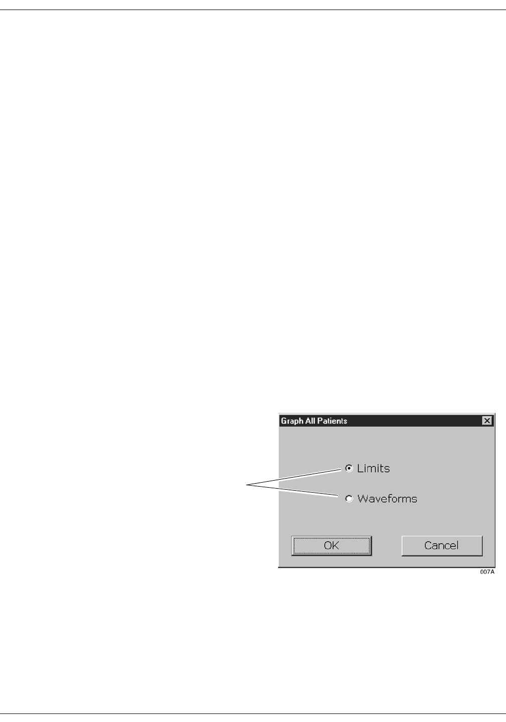
Graph All Patients . . . . . . . . . . . . . . . . . . . . . . . . . . . . . . . . . . . . . . . . . . . . . . . . . . . 9-6
Initiating a Graph All Patients Request . . . . . . . . . . . . . . . . . . . . . . . . . . . . . . . . 9-7
Graph Location Defaults . . . . . . . . . . . . . . . . . . . . . . . . . . . . . . . . . . . . . . . . . . . . . . 9-8
Stopping a Graph . . . . . . . . . . . . . . . . . . . . . . . . . . . . . . . . . . . . . . . . . . . . . . . . . . . . 9-9
Graph Paper Out Indicator . . . . . . . . . . . . . . . . . . . . . . . . . . . . . . . . . . . . . . . . . . . 9-10
Graph Setup Tab Sheet . . . . . . . . . . . . . . . . . . . . . . . . . . . . . . . . . . . . . . . . . . . . . . 9-11
Graph Waveforms Controls . . . . . . . . . . . . . . . . . . . . . . . . . . . . . . . . . . . . . . . . .9-11
ECG 1 Control . . . . . . . . . . . . . . . . . . . . . . . . . . . . . . . . . . . . . . . . . . . . . . .9-11
Waveform 2, Waveform 3, and Waveform 4 . . . . . . . . . . . . . . . . . . . . . . . .9-12
Graph Location Controls . . . . . . . . . . . . . . . . . . . . . . . . . . . . . . . . . . . . . . . . . . .9-12
Manual Graph Location . . . . . . . . . . . . . . . . . . . . . . . . . . . . . . . . . . . . . . . .9-12
Alarm Graph Location . . . . . . . . . . . . . . . . . . . . . . . . . . . . . . . . . . . . . . . . .9-12
Print Window Location . . . . . . . . . . . . . . . . . . . . . . . . . . . . . . . . . . . . . . . . .9-12
Enable Transmitter Graph . . . . . . . . . . . . . . . . . . . . . . . . . . . . . . . . . . . . . .9-13
Alarm Graphs Enabled/Disabled . . . . . . . . . . . . . . . . . . . . . . . . . . . . . . . . .9-13
Graph Speed Controls . . . . . . . . . . . . . . . . . . . . . . . . . . . . . . . . . . . . . . . . . . . . .9-14
Laser Printer . . . . . . . . . . . . . . . . . . . . . . . . . . . . . . . . . . . . . . . . . . . . . . . . . . . . . . . 9-15

Revision A ApexPro Telemetry System vii
2001989-002
10 Patient Data . . . . . . . . . . . . . . . . . . . . . . . . . . . . . . . . . . . 10-1
Introduction . . . . . . . . . . . . . . . . . . . . . . . . . . . . . . . . . . . . . . . . . . . . . . . . . . . . . . . 10-3
Alarm Histories . . . . . . . . . . . . . . . . . . . . . . . . . . . . . . . . . . . . . . . . . . . . . . . . . . . . 10-4
Event Directory . . . . . . . . . . . . . . . . . . . . . . . . . . . . . . . . . . . . . . . . . . . . . . . . . .10-4
Event Window . . . . . . . . . . . . . . . . . . . . . . . . . . . . . . . . . . . . . . . . . . . . . . . . . . .10-5
Alarm Histories Buttons . . . . . . . . . . . . . . . . . . . . . . . . . . . . . . . . . . . . . . . . . . . .10-5
Scan Newer Events . . . . . . . . . . . . . . . . . . . . . . . . . . . . . . . . . . . . . . . . . . .10-5
Scan Older Events . . . . . . . . . . . . . . . . . . . . . . . . . . . . . . . . . . . . . . . . . . . .10-5
Print Directory . . . . . . . . . . . . . . . . . . . . . . . . . . . . . . . . . . . . . . . . . . . . . . .10-5
View Newer Event . . . . . . . . . . . . . . . . . . . . . . . . . . . . . . . . . . . . . . . . . . . .10-5
View Older Event . . . . . . . . . . . . . . . . . . . . . . . . . . . . . . . . . . . . . . . . . . . . .10-6
Delete Event . . . . . . . . . . . . . . . . . . . . . . . . . . . . . . . . . . . . . . . . . . . . . . . .10-6
Learn As . . . . . . . . . . . . . . . . . . . . . . . . . . . . . . . . . . . . . . . . . . . . . . . . . . . .10-6
Relearn . . . . . . . . . . . . . . . . . . . . . . . . . . . . . . . . . . . . . . . . . . . . . . . . . . . .10-7
Graphic Trends . . . . . . . . . . . . . . . . . . . . . . . . . . . . . . . . . . . . . . . . . . . . . . . . . . . . 10-8
Trend Directory Window . . . . . . . . . . . . . . . . . . . . . . . . . . . . . . . . . . . . . . . . . . .10-9
Cursor . . . . . . . . . . . . . . . . . . . . . . . . . . . . . . . . . . . . . . . . . . . . . . . . . . . . . . . . .10-9
Time Resolution Menu . . . . . . . . . . . . . . . . . . . . . . . . . . . . . . . . . . . . . . . . . . . 10-10
Graphic Trends Buttons . . . . . . . . . . . . . . . . . . . . . . . . . . . . . . . . . . . . . . . . . . .10-10
Deselect All . . . . . . . . . . . . . . . . . . . . . . . . . . . . . . . . . . . . . . . . . . . . . . . .10-10
Scan Older . . . . . . . . . . . . . . . . . . . . . . . . . . . . . . . . . . . . . . . . . . . . . . . . .10-10
Scan Newer . . . . . . . . . . . . . . . . . . . . . . . . . . . . . . . . . . . . . . . . . . . . . . . .10-10
Arrow Keys . . . . . . . . . . . . . . . . . . . . . . . . . . . . . . . . . . . . . . . . . . . . . . . . .10-11
Printing Graphic Trends . . . . . . . . . . . . . . . . . . . . . . . . . . . . . . . . . . . . . . . . . . .10-11
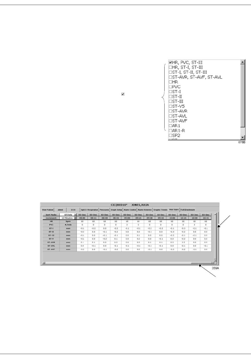
Vital Signs . . . . . . . . . . . . . . . . . . . . . . . . . . . . . . . . . . . . . . . . . . . . . . . . . . . . . . . 10-12
Sort Mode . . . . . . . . . . . . . . . . . . . . . . . . . . . . . . . . . . . . . . . . . . . . . . . . . . . . .10-12
Increment . . . . . . . . . . . . . . . . . . . . . . . . . . . . . . . . . . . . . . . . . . . . . . . . . . . . . .10-13
Scroll Bars . . . . . . . . . . . . . . . . . . . . . . . . . . . . . . . . . . . . . . . . . . . . . . . . . . . . .10-13
Printing Vital Signs . . . . . . . . . . . . . . . . . . . . . . . . . . . . . . . . . . . . . . . . . . . . . . .10-13
Full Disclosure . . . . . . . . . . . . . . . . . . . . . . . . . . . . . . . . . . . . . . . . . . . . . . . . . . . . 10-14
Full Disclosure Options . . . . . . . . . . . . . . . . . . . . . . . . . . . . . . . . . . . . . . . . . . .10-14
Speed . . . . . . . . . . . . . . . . . . . . . . . . . . . . . . . . . . . . . . . . . . . . . . . . . . . . .10-14
Scan Older . . . . . . . . . . . . . . . . . . . . . . . . . . . . . . . . . . . . . . . . . . . . . . . . .10-14
Scan Newer . . . . . . . . . . . . . . . . . . . . . . . . . . . . . . . . . . . . . . . . . . . . . . . .10-15
Older Event . . . . . . . . . . . . . . . . . . . . . . . . . . . . . . . . . . . . . . . . . . . . . . . .10-15
Newer Event . . . . . . . . . . . . . . . . . . . . . . . . . . . . . . . . . . . . . . . . . . . . . . .10-15
View All ECG/Monitor . . . . . . . . . . . . . . . . . . . . . . . . . . . . . . . . . . . . . . . . .10-15
Print Report . . . . . . . . . . . . . . . . . . . . . . . . . . . . . . . . . . . . . . . . . . . . . . . .10-15
Time Focus . . . . . . . . . . . . . . . . . . . . . . . . . . . . . . . . . . . . . . . . . . . . . . . . . . . . . . . 10-16

viii ApexPro Telemetry System Revision A
2001989-002
11 ECG Monitoring . . . . . . . . . . . . . . . . . . . . . . . . . . . . . . . . 11-1
Introduction . . . . . . . . . . . . . . . . . . . . . . . . . . . . . . . . . . . . . . . . . . . . . . . . . . . . . . . 11-3
Data Synchronization . . . . . . . . . . . . . . . . . . . . . . . . . . . . . . . . . . . . . . . . . . . . . .11-3
Patient Preparation . . . . . . . . . . . . . . . . . . . . . . . . . . . . . . . . . . . . . . . . . . . . . . . . . 11-4
Skin Preparation . . . . . . . . . . . . . . . . . . . . . . . . . . . . . . . . . . . . . . . . . . . . . . . . .11-4
Electrode Placement . . . . . . . . . . . . . . . . . . . . . . . . . . . . . . . . . . . . . . . . . . . . . .11-4
5-Leadwire (Einthoven + V Lead) and 6-Leadwire Electrode Placement . .11-5
3-Leadwire Electrode Placement . . . . . . . . . . . . . . . . . . . . . . . . . . . . . . . . .11-6
Electrode Placement for Pediatric Patients . . . . . . . . . . . . . . . . . . . . . . . . .11-6
Modified Chest Lead (MCL) Electrode Placement . . . . . . . . . . . . . . . . . . . .11-7
Electrode Placement for Pacemaker Patients . . . . . . . . . . . . . . . . . . . . . . .11-8
Maintaining Quality ECG Signal . . . . . . . . . . . . . . . . . . . . . . . . . . . . . . . . . .11-8
Special Considerations for 6-Lead Monitoring . . . . . . . . . . . . . . . . . . . . . . . . . . . 11-9
V FAIL Message . . . . . . . . . . . . . . . . . . . . . . . . . . . . . . . . . . . . . . . . . . . . . . . . .11-9
Relearn . . . . . . . . . . . . . . . . . . . . . . . . . . . . . . . . . . . . . . . . . . . . . . . . . . . . . . . .11-9
ECG Monitoring . . . . . . . . . . . . . . . . . . . . . . . . . . . . . . . . . . . . . . . . . . . . . . . . . . . 11-10
ECG in the Multiple Patient Viewer . . . . . . . . . . . . . . . . . . . . . . . . . . . . . . . . . .11-10
ECG in the Single Patient Viewer . . . . . . . . . . . . . . . . . . . . . . . . . . . . . . . . . . 11-11
View Patient Tab Sheet . . . . . . . . . . . . . . . . . . . . . . . . . . . . . . . . . . . . . . .11-11
Full Disclosure Tab Sheet . . . . . . . . . . . . . . . . . . . . . . . . . . . . . . . . . . . . .11-11
ECG Limits . . . . . . . . . . . . . . . . . . . . . . . . . . . . . . . . . . . . . . . . . . . . . . . . . . . . 11-12
ECG Artifact . . . . . . . . . . . . . . . . . . . . . . . . . . . . . . . . . . . . . . . . . . . . . . . . . . . .11-12
ECG Tab Sheet . . . . . . . . . . . . . . . . . . . . . . . . . . . . . . . . . . . . . . . . . . . . . . . . . . . . 11-13
Accessing the ECG Tab Sheet . . . . . . . . . . . . . . . . . . . . . . . . . . . . . . . . . . . . .11-13
Display Lead . . . . . . . . . . . . . . . . . . . . . . . . . . . . . . . . . . . . . . . . . . . . . . . . . . .11-13
Relearn . . . . . . . . . . . . . . . . . . . . . . . . . . . . . . . . . . . . . . . . . . . . . . . . . . . . . . .11-13
Size . . . . . . . . . . . . . . . . . . . . . . . . . . . . . . . . . . . . . . . . . . . . . . . . . . . . . . . . . 11-14
Detect Pace . . . . . . . . . . . . . . . . . . . . . . . . . . . . . . . . . . . . . . . . . . . . . . . . . . . 11-15
Safety Considerations . . . . . . . . . . . . . . . . . . . . . . . . . . . . . . . . . . . . . . . .11-15
Monitoring Pacemaker Patients . . . . . . . . . . . . . . . . . . . . . . . . . . . . . . . . .11-16
Lead Analysis . . . . . . . . . . . . . . . . . . . . . . . . . . . . . . . . . . . . . . . . . . . . . . . . . . 11-18
Arrhythmia . . . . . . . . . . . . . . . . . . . . . . . . . . . . . . . . . . . . . . . . . . . . . . . . . . . . 11-19
Full Arrhythmia Conditions . . . . . . . . . . . . . . . . . . . . . . . . . . . . . . . . . . . . . . . . 11-20
Lethal Arrhythmia Conditions . . . . . . . . . . . . . . . . . . . . . . . . . . . . . . . . . . . . . . .11-22
PVC Limit . . . . . . . . . . . . . . . . . . . . . . . . . . . . . . . . . . . . . . . . . . . . . . . . . . . . . .11-22
ST . . . . . . . . . . . . . . . . . . . . . . . . . . . . . . . . . . . . . . . . . . . . . . . . . . . . . . . . . . .11-22
Va Lead and Vb Lead . . . . . . . . . . . . . . . . . . . . . . . . . . . . . . . . . . . . . . . . . . . .11-23

Revision A ApexPro Telemetry System ix
2001989-002
ST Analysis . . . . . . . . . . . . . . . . . . . . . . . . . . . . . . . . . . . . . . . . . . . . . . . . . . . . . . 11-24
ST Deviation Alarm . . . . . . . . . . . . . . . . . . . . . . . . . . . . . . . . . . . . . . . . . . . . . .11-24
Arrhythmia Troubleshooting . . . . . . . . . . . . . . . . . . . . . . . . . . . . . . . . . . . . . . . . 11-25
Pacemaker Troubleshooting . . . . . . . . . . . . . . . . . . . . . . . . . . . . . . . . . . . . . . . . . 11-26
ST Troubleshooting . . . . . . . . . . . . . . . . . . . . . . . . . . . . . . . . . . . . . . . . . . . . . . . . 11-28
12 SpO2 Monitoring . . . . . . . . . . . . . . . . . . . . . . . . . . . . . . . 12-1
Introduction . . . . . . . . . . . . . . . . . . . . . . . . . . . . . . . . . . . . . . . . . . . . . . . . . . . . . . . 12-3
SpO2 Probe Safety . . . . . . . . . . . . . . . . . . . . . . . . . . . . . . . . . . . . . . . . . . . . . . .12-3
Infants and Pulse Oximetry . . . . . . . . . . . . . . . . . . . . . . . . . . . . . . . . . . . . . . . . . . . 12-4
Signal and Data Validity . . . . . . . . . . . . . . . . . . . . . . . . . . . . . . . . . . . . . . . . . . . . . 12-5
Signal Strength Indicator . . . . . . . . . . . . . . . . . . . . . . . . . . . . . . . . . . . . . . . . . . .12-5
Error Messages . . . . . . . . . . . . . . . . . . . . . . . . . . . . . . . . . . . . . . . . . . . . . . . . . .12-5
SPO2 Monitoring . . . . . . . . . . . . . . . . . . . . . . . . . . . . . . . . . . . . . . . . . . . . . . . . . . . 12-6
SPO2 in the Multiple Patient Viewer . . . . . . . . . . . . . . . . . . . . . . . . . . . . . . . . . .12-6
SPO2 in the Single Patient Viewer . . . . . . . . . . . . . . . . . . . . . . . . . . . . . . . . . . .12-6
SPO2 Limits . . . . . . . . . . . . . . . . . . . . . . . . . . . . . . . . . . . . . . . . . . . . . . . . . . . . 12-7
SPO2 Tab Sheet . . . . . . . . . . . . . . . . . . . . . . . . . . . . . . . . . . . . . . . . . . . . . . . . . . . . 12-8
Accessing the SPO2 Tab Sheet . . . . . . . . . . . . . . . . . . . . . . . . . . . . . . . . . . . . .12-8
Rate . . . . . . . . . . . . . . . . . . . . . . . . . . . . . . . . . . . . . . . . . . . . . . . . . . . . . . . . . . .12-8
Size . . . . . . . . . . . . . . . . . . . . . . . . . . . . . . . . . . . . . . . . . . . . . . . . . . . . . . . . . . .12-8
Troubleshooting . . . . . . . . . . . . . . . . . . . . . . . . . . . . . . . . . . . . . . . . . . . . . . . . . . . . 12-9
SpO2 Messages . . . . . . . . . . . . . . . . . . . . . . . . . . . . . . . . . . . . . . . . . . . . . . . . .12-9
13 NBP Monitoring . . . . . . . . . . . . . . . . . . . . . . . . . . . . . . . . 13-1
Introduction . . . . . . . . . . . . . . . . . . . . . . . . . . . . . . . . . . . . . . . . . . . . . . . . . . . . . . . 13-3
Safety Considerations . . . . . . . . . . . . . . . . . . . . . . . . . . . . . . . . . . . . . . . . . . . . . . . 13-4
Programming the Blood Pressure Monitor . . . . . . . . . . . . . . . . . . . . . . . . . . . . . . 13-5
Setting the Measurement Interval . . . . . . . . . . . . . . . . . . . . . . . . . . . . . . . . . . . .13-5
Setting Test Parameters . . . . . . . . . . . . . . . . . . . . . . . . . . . . . . . . . . . . . . . . . . .13-6
Setting Limits . . . . . . . . . . . . . . . . . . . . . . . . . . . . . . . . . . . . . . . . . . . . . . . . . . . .13-7
Software and Hardware Versions . . . . . . . . . . . . . . . . . . . . . . . . . . . . . . . . . . . .13-7

x ApexPro Telemetry System Revision A
2001989-002
Patient Preparation . . . . . . . . . . . . . . . . . . . . . . . . . . . . . . . . . . . . . . . . . . . . . . . . . 13-8
Microphone Placement . . . . . . . . . . . . . . . . . . . . . . . . . . . . . . . . . . . . . . . . . . . .13-9
Placement in the Microphone Pad . . . . . . . . . . . . . . . . . . . . . . . . . . . . . . . .13-9
Placement in the Blood Pressure Cuff . . . . . . . . . . . . . . . . . . . . . . . . . . . .13-10
NBP Monitoring . . . . . . . . . . . . . . . . . . . . . . . . . . . . . . . . . . . . . . . . . . . . . . . . . . . 13-11
NBP in the Multiple Patient Viewer . . . . . . . . . . . . . . . . . . . . . . . . . . . . . . . . . .13-11
NBP in the Single Patient Viewer . . . . . . . . . . . . . . . . . . . . . . . . . . . . . . . . . . . .13-11
NBP Limits . . . . . . . . . . . . . . . . . . . . . . . . . . . . . . . . . . . . . . . . . . . . . . . . . . . . .13-11
Pressures Tab Sheet . . . . . . . . . . . . . . . . . . . . . . . . . . . . . . . . . . . . . . . . . . . . . . . 13-12
Accessing the Pressures Tab Sheet . . . . . . . . . . . . . . . . . . . . . . . . . . . . . . . . .13-12
Auto . . . . . . . . . . . . . . . . . . . . . . . . . . . . . . . . . . . . . . . . . . . . . . . . . . . . . . . . . 13-13
Cuff Size . . . . . . . . . . . . . . . . . . . . . . . . . . . . . . . . . . . . . . . . . . . . . . . . . . . . . .13-13
Clear Message . . . . . . . . . . . . . . . . . . . . . . . . . . . . . . . . . . . . . . . . . . . . . . . . . .13-13
Troubleshooting . . . . . . . . . . . . . . . . . . . . . . . . . . . . . . . . . . . . . . . . . . . . . . . . . . 13-14
NBP Status Messages . . . . . . . . . . . . . . . . . . . . . . . . . . . . . . . . . . . . . . . . . . . .13-14
14 Appendices . . . . . . . . . . . . . . . . . . . . . . . . . . . . . . . . . . . 14-1
Appendix A — Message Glossary . . . . . . . . . . . . . . . . . . . . . . . . . . . . . . . . . . . . . 14-3
Alarm Messages . . . . . . . . . . . . . . . . . . . . . . . . . . . . . . . . . . . . . . . . . . . . . . . . .14-3
Graph Messages . . . . . . . . . . . . . . . . . . . . . . . . . . . . . . . . . . . . . . . . . . . . . . . . .14-5
Transmitter-Related Messages . . . . . . . . . . . . . . . . . . . . . . . . . . . . . . . . . . . . . .14-5
System Status Messages . . . . . . . . . . . . . . . . . . . . . . . . . . . . . . . . . . . . . . . . . 14-6
Patient Status Messages . . . . . . . . . . . . . . . . . . . . . . . . . . . . . . . . . . . . . . . . . . .14-6
Appendix B — Supplies . . . . . . . . . . . . . . . . . . . . . . . . . . . . . . . . . . . . . . . . . . . . . 14-7
Appendix C — Technical Specifications . . . . . . . . . . . . . . . . . . . . . . . . . . . . . . . . 14-8
ApexPro Transmitter . . . . . . . . . . . . . . . . . . . . . . . . . . . . . . . . . . . . . . . . . . . . . .14-8
Apex Oximeter . . . . . . . . . . . . . . . . . . . . . . . . . . . . . . . . . . . . . . . . . . . . . . . . . 14-12
Accutracker DX Noninvasive Blood Pressure Monitor . . . . . . . . . . . . . . . . . . . 14-13
ApexPro Receiver System . . . . . . . . . . . . . . . . . . . . . . . . . . . . . . . . . . . . . . . . 14-15
ApexPro Antenna System . . . . . . . . . . . . . . . . . . . . . . . . . . . . . . . . . . . . . . . . 14-17
Appendix D — Abbreviations and Symbols . . . . . . . . . . . . . . . . . . . . . . . . . . . . 14-18
Abbreviations . . . . . . . . . . . . . . . . . . . . . . . . . . . . . . . . . . . . . . . . . . . . . . . . . . .14-18
Symbols . . . . . . . . . . . . . . . . . . . . . . . . . . . . . . . . . . . . . . . . . . . . . . . . . . . . . . .14-20
Index . . . . . . . . . . . . . . . . . . . . . . . . . . . . . . . . . . . . . . . Index-1

Revision A ApexPro Telemetry System 1-1
2001989-002
1The Basics
About This Manual . . . . . . . . . . . . . . . . . . . . . . . . . . . . . . . . . . . . . . . . . . . . . . . . . . . 1-3
Manual Purpose . . . . . . . . . . . . . . . . . . . . . . . . . . . . . . . . . . . . . . . . . . . . . . . . . . .1-3
Intended Audience . . . . . . . . . . . . . . . . . . . . . . . . . . . . . . . . . . . . . . . . . . . . . . . . .1-3
Revision History . . . . . . . . . . . . . . . . . . . . . . . . . . . . . . . . . . . . . . . . . . . . . . . . . . .1-3
Manual Conventions . . . . . . . . . . . . . . . . . . . . . . . . . . . . . . . . . . . . . . . . . . . . . . . . . 1-4
Product References . . . . . . . . . . . . . . . . . . . . . . . . . . . . . . . . . . . . . . . . . . . . . . . .1-4
Definitions . . . . . . . . . . . . . . . . . . . . . . . . . . . . . . . . . . . . . . . . . . . . . . . . . . . . . . .1-4
Illustrations . . . . . . . . . . . . . . . . . . . . . . . . . . . . . . . . . . . . . . . . . . . . . . . . . . . . . . .1-5
Common Operations . . . . . . . . . . . . . . . . . . . . . . . . . . . . . . . . . . . . . . . . . . . . . . . . . 1-6
“Clicking” the Mouse . . . . . . . . . . . . . . . . . . . . . . . . . . . . . . . . . . . . . . . . . . . . . . .1-6
Radio Buttons . . . . . . . . . . . . . . . . . . . . . . . . . . . . . . . . . . . . . . . . . . . . . . . . . . . .1-6
Check Boxes . . . . . . . . . . . . . . . . . . . . . . . . . . . . . . . . . . . . . . . . . . . . . . . . . . . . 1-7
Scroll Bars . . . . . . . . . . . . . . . . . . . . . . . . . . . . . . . . . . . . . . . . . . . . . . . . . . . . . . .1-7
Popup Lists . . . . . . . . . . . . . . . . . . . . . . . . . . . . . . . . . . . . . . . . . . . . . . . . . . . . . 1-8
Unit Defaults Worksheet . . . . . . . . . . . . . . . . . . . . . . . . . . . . . . . . . . . . . . . . . . . . . . 1-9


Revision A ApexPro Telemetry System 1-3
2001989-002
The Basics: About This Manual
About This Manual
Manual Purpose
This manual contains the instructions necessary to operate the ApexPro
telemetry system safely and in accordance with its function and intended
use.
This manual addresses the operation of the ApexPro telemetry system at
the Clinical Information Center. Be sure to read the entire manual before
using the equipment.
Intended Audience
This manual is geared for clinical professionals. Clinical professionals
are expected to have a working knowledge of medical procedures,
practices, and terminology, as required for monitoring of critically ill
patients.
This manual assumes that you are familiar with the operating
procedures of the Clinical Information Center. If you would like more
information about using the Clinical Information Center, refer to the
Clinical Information Center Operator’s Manual.
This manual also assumes that you are familiar with the operation of a
two-button computer mouse. If you would like more information about
operating the mouse, refer to the Clinical Information Center Operator’s
Manual, or to the documentation supplied with the mouse.
Revision History
Each page of the document has the document part number and revision
letter at the bottom of the page. The revision letter changes whenever
the document is updated.
Revision Date Comments
A 5 June 2000 Initial release of this document, corresponding to
ApexPro telemetry system software version 1.

1-4 ApexPro Telemetry System Revision A
2001989-002
The Basics: Manual Conventions
Manual Conventions
This section describes terminology, standards, and other conventions
that are used throughout this manual.
Product References
In this manual:
The ApexPro telemetry system is referred to as the ApexPro system,
or simply the system.
The Clinical Information Center is referred to as the clinical
information center, the CIC, or the central station.
The SunTech Medical Systems Accutracker DX noninvasive blood
pressure monitor is referred to as the blood pressure monitor or the
Accutracker.
The PRN 50 Digital Writer is referred to as the digital writer or the
writer.
The Direct Digital Writers are referred to as DDWs or writers.
The laser printer is referred to as the printer.
Definitions
The following terms are used in this manual:
Buttons — The word “button” is defined in two ways:
1. A button is a labeled gray or red rectangle on the clinical information
center. Clicking on a button with the mouse pointer opens a tab sheet
or performs the specified action (such as Print). Red buttons are used
to view beds in alarm.
2. A button is a labeled circle, square, or rectangle located on the
ApexPro transmitter, the Apex Oximeter, or the Accutracker blood
pressure monitor. Pressing the button with your finger activates it.
127(The computer mouse used with the clinical information center
also has two buttons. Refer to the Clinical Information Center
Operator’s Manual for information about using those buttons.
Messages/Prompts — A message is text that appears on the clinical
information center. It informs you of conditions occurring that are not
necessarily part of normal operating conditions. Prompts are text
messages that appear, instructing you to perform a specific action.
Multiple patient viewer — The multiple patient viewer is the clinical
information center display in its normal state. Bed windows for admitted
patients are shown, as well as a menu bar at the bottom of the display.
Screen text — Any text that appears on the clinical information center
display. In this manual, screen text is shown in italics (for example,
ECG, SAVING, etc.).

Revision A ApexPro Telemetry System 1-5
2001989-002
The Basics: Manual Conventions
Single patient viewer — When you click on a patient’s bed window at
the clinical information center, the display rearranges to accommodate a
set of tab sheets (see definition below) in the bottom portion of the
display. This set of tab sheets is referred to as the single patient viewer
because it contains information specific to one patient.
Tab options — Tab options are the choices and text entry fields
available on a tab sheet. The information presented as tab options may
pertain to a patient’s data, or may be control information (such as alarm
settings) that can be modified to meet the user’s specific needs.
Tab sheets — Tab sheets look like labeled index cards. The menu tab
labels indicate the type of information to be viewed and/or changed on its
tab sheet. Clicking on a tab brings its tab sheet to the front of the “index
card” stack, or to the front of the currently viewed window.
Tabs — Tabs are the labeled section of the tab sheets. Clicking on a tab
brings its tab sheet to the front. Tab and tab sheet are sometimes used
interchangeably.
Illustrations
All illustrations in this manual are provided as examples only. They may
not necessarily reflect your telemetry monitoring setup or data displayed
on your equipment.
1-6 ApexPro Telemetry System Revision A
2001989-002
The Basics: Common Operations
Common Operations
Some operations are used repetitively at the clinical information center
or the ApexPro telemetry system. Rather than explaining how to perform
each operation every time it appears in this manual, these operations are
presented below. Please familiarize yourself with the proper procedure
for each.
“Clicking” the Mouse
The term “click” refers to positioning the mouse pointer on a selection
and pressing the left mouse button one time.
In situations where the right mouse button should be pressed, this is
specifically called out. In all other cases, assume that you should press
the left mouse button.
Pressing the mouse button two times in a row is called double clicking. In
situations where the mouse needs to be double clicked to perform a
function, this is specifically called out. In all other cases, assume that you
only need to click the mouse button one time.
Radio Buttons
To use a radio button control, click on the white circle (radio button) or
the text next to it. When selected, a black dot is shown in the white circle.
To deselect a radio button control, click again on the label text or in the
white circle. When it is not selected, no black dot is shown.
Radio Buttons —
“Dot” in center
indicates active
selection.
Revision A ApexPro Telemetry System 1-7
2001989-002
The Basics: Common Operations
Check Boxes
To use check box controls, click on the square or the text next to it. When
selected, a check mark is shown in this square. To deselect a check box
control, click again on the text or in the square. When deselected, no
check mark is shown.
Scroll Bars
Use horizontal and vertical scroll bars to move a window’s contents left/
right and up/down. Place the mouse pointer on the appropriate arrow to
move the scroll bar, or click and hold the mouse button down while
dragging the scroll bar until the desired information is displayed.
Check Boxes —
indicates active
selection.
Horizontal
Scroll Bar
Vertical
Scroll
Bar
1-8 ApexPro Telemetry System Revision A
2001989-002
The Basics: Common Operations
Popup Lists
Clicking in a text field may produce a down arrow button on the right
side of the field. This arrow button is used to open a popup list. A popup
list is a list of options available for that particular field. Use the mouse to
click on the arrow button, which opens the popup list.
Once the popup list is open, use the mouse to click on an option. This
selects the option and closes the popup list.
127(If you click on the right side of a field, the down arrow button
and the popup list of selections may appear simultaneously.
Arrow Button —
indicates there is a
popup list.
Popup List

Revision A ApexPro Telemetry System 1-9
2001989-002
The Basics: Unit Defaults Worksheet
Unit Defaults Worksheet
This worksheet has been provided as an optional reference tool to record
your care unit’s default settings. Fill out the information and keep it in a
prominent place to refer to your setup. Before you fill it out, you may
want to make additional copies of the worksheet for future use.
Unit Defaults — Arrhythmia Alarm Levels
Date: Unit:
Crisis Warning Advisory Message
Asystole
VFIB/VTAC
V Tach
VT > 2
V Brady
Couplet
Bigeminy
Acc Vent
Pause
Trigeminy
R on T
PVC
Tachy
Brady
Irregular

1-10 ApexPro Telemetry System Revision A
2001989-002
The Basics: Unit Defaults Worksheet
Unit Defaults — Parameter Alarm Levels
Unit Defaults — Limits
Crisis Warning Advisory Message
HR
NBP-S
NBP-D
NBP-M
SPO2
SPO2-R
PVC
ST-I
ST-II
ST-III
ST-V
ST-V2
ST-V3
ST-V4
ST-V5
ST-V6
ST-AVR
ST-AVL
ST-AVF
Low High
HR
PVC (number per minute limit)
NBP-S
NBP-D
NBP-M
SPO2
SPO2-R

Revision A ApexPro Telemetry System 1-11
2001989-002
The Basics: Unit Defaults Worksheet
Unit Defaults — Telemetry
Manual Graph Location
Alarm Graph Location
Print Window Graph Location
ECG 1 Waveform Display
Waveform 2 Display
Waveform 3 Display
Waveform 4 Display
Transmitter Graph
Alarm Graph On/Off
Display Lead
Arrhythmia
Lead Analysis
ST Analysis
Va Lead
Vb Lead
Detect Pace
Patient Data Transfer PIRP Server
Patient Data Transfer PDT Server
Patient Age
Transmitter Alarm Pause
Alarm Pause Breakthrough

1-12 ApexPro Telemetry System Revision A
2001989-002
The Basics: Unit Defaults Worksheet
For your notes

Revision A ApexPro Telemetry System 2-1
2001989-002
2Safety
For Your Safety . . . . . . . . . . . . . . . . . . . . . . . . . . . . . . . . . . . . . . . . . . . . . . . . . . . . . 2-3
Intended Use . . . . . . . . . . . . . . . . . . . . . . . . . . . . . . . . . . . . . . . . . . . . . . . . . . . . .2-3
Definitions . . . . . . . . . . . . . . . . . . . . . . . . . . . . . . . . . . . . . . . . . . . . . . . . . . . . . . .2-3
System Safety . . . . . . . . . . . . . . . . . . . . . . . . . . . . . . . . . . . . . . . . . . . . . . . . . . . .2-3
Dangers . . . . . . . . . . . . . . . . . . . . . . . . . . . . . . . . . . . . . . . . . . . . . . . . . . . . .2-3
Warnings . . . . . . . . . . . . . . . . . . . . . . . . . . . . . . . . . . . . . . . . . . . . . . . . . . . .2-4
Cautions . . . . . . . . . . . . . . . . . . . . . . . . . . . . . . . . . . . . . . . . . . . . . . . . . . . . .2-7
Notes . . . . . . . . . . . . . . . . . . . . . . . . . . . . . . . . . . . . . . . . . . . . . . . . . . . . . . .2-9
Reference Literature . . . . . . . . . . . . . . . . . . . . . . . . . . . . . . . . . . . . . . . . . . . . . 2-10
Classification . . . . . . . . . . . . . . . . . . . . . . . . . . . . . . . . . . . . . . . . . . . . . . . . . . . .2-10
Underwriters Laboratories, Inc. . . . . . . . . . . . . . . . . . . . . . . . . . . . . . . . . . . . . . .2-10
Equipment Symbols . . . . . . . . . . . . . . . . . . . . . . . . . . . . . . . . . . . . . . . . . . . . . . 2-11


Revision A ApexPro Telemetry System 2-3
2001989-002
Safety: For Your Safety
For Your Safety
Intended Use
The ApexPro telemetry system is intended to acquire and monitor
physiological data for ambulating patients within a defined coverage
area. It is intended for installation in the hospital or clinical environment
to provide clinicians with patient physiological data while allowing for
patient mobility. The physiological parameters monitored include ECG,
noninvasive blood pressure, and SpO2.
Definitions
The terms danger, warning, and caution are used throughout this
manual to point out hazards and to designate a degree or level or
seriousness. Familiarize yourself with their definitions and significance.
Hazard is defined as a source of potential injury to a person.
DANGER indicates an imminent hazard which, if not avoided, will
result in death or serious injury.
WARNING indicates a potential hazard or unsafe practice which, if not
avoided, could result in death or serious injury.
CAUTION indicates a potential hazard or unsafe practice which, if not
avoided, could result in minor personal injury or product/property
damage.
NOTE provides application tips or other useful information to assure
that you get the most from your equipment.
System Safety
The safety statements presented in this chapter refer to the equipment
in general and, in most cases, apply to all aspects of the telemetry
system. There are additional safety statements in other chapters that are
specific to the information presented in that chapter.
The order in which safety statements are presented in no way implies
order of importance.
Dangers There are no dangers that refer to the equipment in general. Specific
“Danger” statements may be given in the respective sections of this
manual.

2-4 ApexPro Telemetry System Revision A
2001989-002
Safety: For Your Safety
Warnings
:$51,1*6
ACCIDENTAL SPILLS — To avoid electric shock or
device malfunction liquids must not be allowed to enter
the device. If liquids have entered a device, take it out of
service and have it checked by a service technician before
it is used again.
ACCURACY — If the accuracy of any value displayed on
the monitor, central station, or printed on a graph strip is
questionable, determine the patient's vital signs by
alternative means. Verify that all equipment is working
correctly.
ALARMS — Do not rely exclusively on the audible alarm
system for patient monitoring. Adjustment of alarm
volume to a low level or off during patient monitoring
may result in a hazard to the patient.
Do not rely exclusively on the alarm pause breakthrough
feature for alarm notification during an alarm pause.
This may result in a hazard to the patient. Only crisis
alarms break through an alarm pause.
Remember that the most reliable method of patient
monitoring combines close personal surveillance with
correct operation of monitoring equipment.
After connecting the monitor to the central station,
nurse-call system, and/or network, verify the function of
the alarm system.
The functions of the alarm system for monitoring of the
patient must be verified at regular intervals.
BEFORE USE — Before putting the system into
operation visually inspect all connecting cables for signs
of damage. Damaged cables and connectors must be
replaced immediately.
Before using the system, the operator must verify that it
is in correct working order and operating condition.
Periodically, and whenever the integrity of the product is
in doubt, test all functions.
CABLES — Route all cables away from patient's throat
to avoid possible strangulation.

Revision A ApexPro Telemetry System 2-5
2001989-002
Safety: For Your Safety
:$51,1*6
CONDUCTIVE CONNECTIONS — Extreme care must
be exercised when applying medical electrical equipment.
Many parts of the human/machine circuit are conductive,
such as the patient, connectors, electrodes, transducers.
It is very important that these conductive parts do not
come into contact with other grounded, conductive parts
when connected to the isolated patient input of the
device. Such contact would bridge the patient's isolation
and cancel the protection provided by the isolated input.
In particular, there must be no contact of the neutral
electrode and ground.
DEFIBRILLATION — Do not come into contact with
patients during defibrillation. Otherwise serious injury
or death could result.
DISCONNECTION FROM MAINS — When
disconnecting the system from the power line, remove the
plug from the wall outlet first. Then you may disconnect
the power cord from the device. If you do not observe this
sequence, there is a risk of coming into contact with line
voltage by inserting metal objects, such as the pins of
leadwires, into the sockets of the power cord by mistake.
DISPOSAL — Dispose of the packaging material,
observing the applicable waste control regulations and
keeping it out of children's reach.
EXPLOSION HAZARD — Do not use this equipment in
the presence of flammable anesthetics, vapors or liquids.
INTERFACING OTHER EQUIPMENT — Devices may
only be interconnected with each other or to parts of the
system when it has been determined by qualified
biomedical engineering personnel that there is no danger
to the patient, the operator, or the environment as a
result. In those instances where there is any element of
doubt concerning the safety of connected devices, the user
must contact the manufacturers concerned (or other
informed experts) for proper use. In all cases, safe and
proper operation should be verified with the applicable
manufacturer's instructions for use, and system
standards IEC 60601-1-1/EN 60601-1-1 must be complied
with.
LEAKAGE CURRENT TEST — When interfacing with
other equipment, a test for leakage current must be
performed by qualified biomedical engineering personnel
before using with patients.
2-6 ApexPro Telemetry System Revision A
2001989-002
Safety: For Your Safety
:$51,1*6
NETWORK INTEGRITY — The clinical information
center resides on the hospital’s computer network, and it
is possible that inadvertent or malicious network activity
could adversely affect patient monitoring. The integrity
of the computer network is the responsibility of the
hospital.
POWER SUPPLY — The device must be connected to a
properly installed power outlet with protective earth
contacts only.
All devices of a system must be connected to the same
power supply circuit. Devices which are not connected to
the same circuit must be electrically isolated when
operated (electrically isolated RS232 interface).
Do not use this power unit in the presence of flammable
anesthetics.
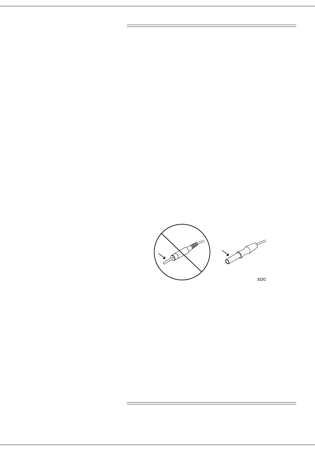
PROTECTED LEADWIRES — Only use protected
leadwires and patient cables with this device. The use of
unprotected leadwires and patient cables creates the
potential for making an electrical connection to ground or
to a high voltage power source which can cause serious
injury or death to the patient.
RATE METERS — Keep pacemaker patients under close
observation. Rate meters may continue to count the
pacemaker rate during cardiac arrest and some
arrhythmias. Therefore, do not rely entirely on rate
meter alarms.
SITE REQUIREMENTS — For safety reasons, all
connectors for patient cables and sensor leads are
designed to prevent inadvertent disconnection, should
someone pull on them. Do not route cables in a way that
they may present a stumbling hazard. For devices
installed above the patient, adequate precautions must
be taken to prevent them from dropping on the patient.
Unprotected Leadwire Protected Leadwire

Revision A ApexPro Telemetry System 2-7
2001989-002
Safety: For Your Safety
Cautions
&$87,216
ACCESSORIES (SUPPLIES) — To ensure patient safety,
use only parts and accessories manufactured or
recommended by GE Marquette Medical Systems.
Parts and accessories used must meet the requirements
of the applicable IEC 60601 series safety standards and
essential performance standards, and/or the system
configuration must meet the requirements of the IEC
60601-1-1 medical electrical systems standard.
ACCESSORIES (EQUIPMENT) — The use of
ACCESSORY equipment not complying with the
equivalent safety requirements of this equipment may
lead to a reduced level of safety of the resulting system.
Consideration relating to the choice shall include:
use of the accessory in the PATIENT VICINITY; and
evidence that the safety certification of the
ACCESSORY has been performed in accordance to
the appropriate IEC 60601-1 and/or IEC 60601-1-1
harmonized national standard.
BEFORE INSTALLATION — Compatibility is critical to
safe and effective use of this device. Please contact your
local sales or service representative prior to installation
to verify equipment compatibility.
DEFIBRILLATOR PRECAUTIONS — Patient signal
inputs labeled with the CF and BF symbols with paddles
are protected against damage resulting from
defibrillation voltages. To ensure proper defibrillator
protection, use only the recommended cables and
leadwires.
Proper placement of defibrillator paddles in relation to
the electrodes is required to ensure successful
defibrillation.
DISPOSABLES — Disposable devices are intended for
single use only. They should not be reused as
performance could degrade or contamination could occur.
DISPOSAL — At the end of its service life, the product
described in this manual, as well as its accessories, must
be disposed of in compliance with the guidelines
regulating the disposal of such products. If you have
questions concerning disposal of the product, please
contact GE Marquette Medical Systems or its
representatives.

2-8 ApexPro Telemetry System Revision A
2001989-002
Safety: For Your Safety
&$87,216
ELECTROCAUTERY PRECAUTIONS — To prevent
unwanted skin burns, apply electrocautery electrodes as
far as possible from all other electrodes, a distance of at
least 15 cm/6 in. is recommended.
EMC — Magnetic and electrical fields are capable of
interfering with the proper performance of the device.
For this reason make sure that all external devices
operated in the vicinity of the monitoring system comply
with the relevant EMC requirements. X-ray equipment
or MRI devices are a possible source of interference as
they may emit higher levels of electromagnetic radiation.
INSTRUCTIONS FOR USE — For continued safe use of
this equipment, it is necessary that the listed
instructions are followed. However, instructions listed in
this manual in no way supersede established medical
practices concerning patient care.
LOSS OF DATA — Should the monitor at any time
temporarily lose patient data, the potential exists that
active monitoring is not being done. Close patient
observation or alternate monitoring devices should be
used until monitor function is restored.
Once monitoring is restored, you should verify correct
monitoring state and alarm function.
MAINTENANCE — Regular preventive maintenance
should be carried out annually. You are responsible for
any requirements specific to your country.
MPSO — The use of a multiple portable socket outlet
(MPSO) for a system will result in an enclosure leakage
current equal to the sum of all individual earth leakage
currents of the system if there is an interruption of the
MPSO protective earth conductor. Do not use an
additional extension cable with the MPSO as it will
increase the chance of the single protective earth
conductor interruption.
NEGLIGENCE — GE Marquette Medical Systems does
not assume responsibility for damage to the equipment
caused by improperly vented cabinets, improper or faulty
power, or insufficient wall strength to support equipment
mounted on such walls.
OPERATOR — Medical technical equipment such as this
monitor/monitoring system must only be used by persons
who have received adequate training in the use of such
equipment and who are capable of applying it properly.

Revision A ApexPro Telemetry System 2-9
2001989-002
Safety: For Your Safety
&$87,216
POWER REQUIREMENTS — Before connecting the
device to the power line, check that the voltage and
frequency ratings of the power line are the same as those
indicated on the unit's label. If this is not the case, do not
connect the system to the power line until you adjust the
unit to match the power source.
RESTRICTED SALE — U.S. federal law restricts this
device to sale by or on the order of a physician.
SECURITY — The web browser which runs in
conjunction with the clinical information center is
intended for hospital INTRANET use only. If confidential
patient information is made available from the hospital
intranet, the security of the data is the responsibility of
the hospital.
SUPERVISED USE — This equipment is intended for
use under the direct supervision of a licensed health care
practitioner.
UNINTENTIONAL RADIO FREQUENCY (RF)
INTERFERENCE — Unintentional RF interference
could degrade the reliability and performance of the
wireless data link. The facility must maintain an RF
environment free from unintentional interference. Refer
to the service manuals for more information.
VENTILATION REQUIREMENTS — Set up the device
in a location which affords sufficient ventilation. The
ventilation openings of the device must not be obstructed.
The ambient conditions specified in the technical
specifications must be ensured at all times.
Notes Put the system in a location where you can easily see the screen and
access the operating controls.
This product is not likely to cause abnormal operation of other
patient-connected equipment such as cardiac pacemakers or other
electrical stimulators. Exceptions are noted in the pacemaker
monitoring section, if applicable.
This product is protected against the effects of cardiac defibrillator
discharges to ensure proper recovery, as required by test standards.

2-10 ApexPro Telemetry System Revision A
2001989-002
Safety: For Your Safety
Reference Literature
Medical Device Directive 93/42/EEC.
EN 60601-1/1990 + A1: 1993 + A2: 1995: Medical electrical equipment.
General requirements for safety.
EN 60601-1-1/9.1994 + A1 12.95: General requirements for safety.
Requirements for the safety of medical electrical systems.
IEC Publication 513/1994: Fundamental aspects of safety standards for
medical equipment.
ROY, O.Z.: Summary of cardiac fibrillation thresholds for 60-Hz currents
and voltages applied directly to the heart. Med. & Biol. Engn. &
Computing 18: 657...659 (1980).
Classification
The telemetry system is classified, according to IEC 60601-1, as:
Underwriters Laboratories, Inc.
Classified by Underwriters Laboratories Inc. with respect
to electric shock, fire, mechanical and other specified
hazards, only in accordance with UL 2601-1, CAN/CSA
C22.2 No. 601.1, IEC 60601-1, and, if required, IEC 60601-
2-27, IEC 60601-2-30, IEC 60601-2-34, IEC 60601-1-1.
Type of protection against electrical shock Transmitter — Internally powered
Receiver system — Class I
Degree of protection against electrical
shock Transmitter — Type B Equipment
Degree of protection against harmful
ingress of water Transmitter — IPX3 (IEC 529)
Receiver system — Ordinary Equipment (enclosed equipment without protection
against ingress of water)
Degree of safety of application in the
presence of a flammable anesthetic
mixture with air or with oxygen or nitrous
oxide
Equipment not suitable for use in the presence of a flammable anesthetic mixture
with air or with oxygen or nitrous oxide
Method(s) of sterilization or disinfection
recommended by the manufacturer Not applicable
Mode of operation Continuous operation
Revision A ApexPro Telemetry System 2-11
2001989-002
Safety: For Your Safety
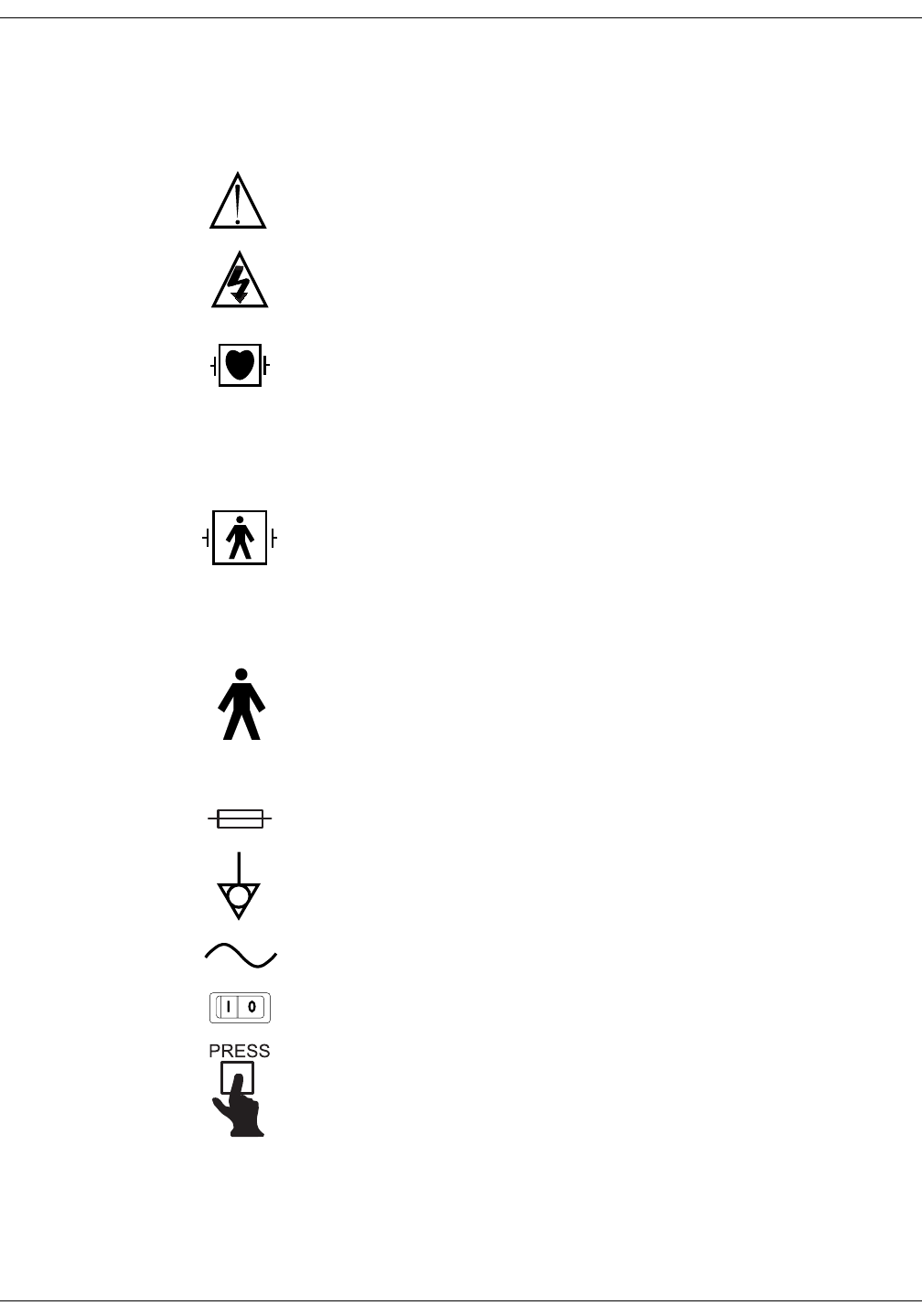
Equipment Symbols
127(Some symbols may not appear on all equipment.
ATTENTION: Consult accompanying documents.
CAUTION: To reduce the risk of electric shock, do NOT remove cover. Refer servicing to
qualified service personnel.
127(The rating
of protection
against electric
shock (indicated by
symbol for CF or
BF) is achieved only
when used with
patient applied
parts recommended
by GE Marquette.
TYPE CF APPLIED PART: Isolated (floating) applied part suitable for intentional external and
internal application to the patient including direct cardiac application. “Paddles” outside the
box indicate the applied part is defibrillator proof.
[Medical Standard Definition:] F-type applied part (floating/isolated) complying with the
specified requirements of IEC 60601-1/UL 2601-1/CSA 601.1 Medical Standards to provide a
higher degree of protection against electric shock than that provided by type BF applied parts.
TYPE BF APPLIED PART: Isolated (floating) applied part suitable for intentional external and
internal application to the patient excluding direct cardiac application. “Paddles” outside the
box indicate the applied part is defibrillator proof.
[Medical Standard Definition:] F-type applied part (floating/isolated) complying with the
specified requirements of IEC 60601-1/UL 2601-1/CSA 601.1 Medical Standards to provide a
higher degree of protection against electric shock than that provided by type B applied parts.
TYPE B APPLIED PART: Non-isolated applied part suitable for intentional external and
internal application to the patient excluding direct cardiac application.
[Medical Standard Definition:] Applied part complying with the specified requirements of IEC
60601-1/UL 2601-1/CSA 601.1 Medical Standards to provide protection against electric
shock, particularly regarding allowable leakage current.
Fuse
Equipotentiality
Alternating current (AC)
Power; I = ON; O = OFF
Indicates where to press to open the door on the 7160 DDW.

2-12 ApexPro Telemetry System Revision A
2001989-002
Safety: For Your Safety
For your notes

Revision A ApexPro Telemetry System 3-1
2001989-002
3Equipment Overview
Introduction . . . . . . . . . . . . . . . . . . . . . . . . . . . . . . . . . . . . . . . . . . . . . . . . . . . . . . . . 3-3
ApexPro Telemetry System . . . . . . . . . . . . . . . . . . . . . . . . . . . . . . . . . . . . . . . . . . . 3-4
Compatibility with Bedside Monitors . . . . . . . . . . . . . . . . . . . . . . . . . . . . . . . . . . .3-4
ApexPro Transmitter . . . . . . . . . . . . . . . . . . . . . . . . . . . . . . . . . . . . . . . . . . . . . . 3-5
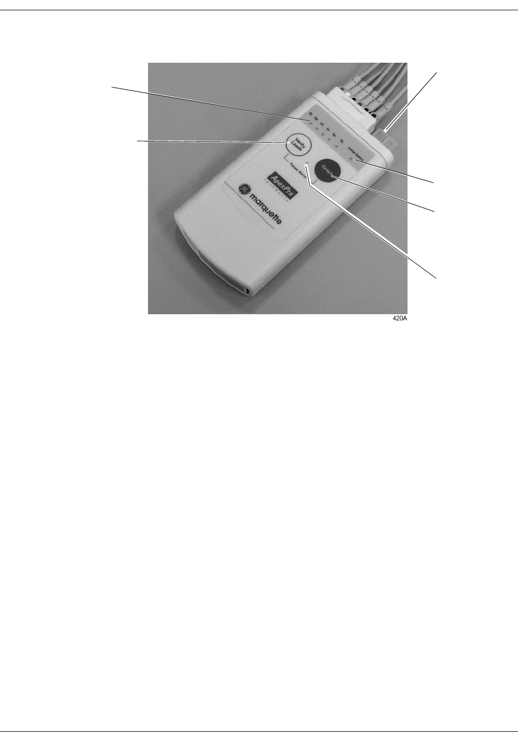
ApexPro Transmitter Buttons and LEDs . . . . . . . . . . . . . . . . . . . . . . . . . . . .3-6
Apex Oximeter SpO2 Module . . . . . . . . . . . . . . . . . . . . . . . . . . . . . . . . . . . . . . . 3-8
Apex Oximeter Buttons and LEDs . . . . . . . . . . . . . . . . . . . . . . . . . . . . . . . . .3-8
Accutracker DX Noninvasive Blood Pressure (NBP) Monitor . . . . . . . . . . . . . . . .3-9
Accutracker DX Buttons and Switches . . . . . . . . . . . . . . . . . . . . . . . . . . . .3-10
Antenna System . . . . . . . . . . . . . . . . . . . . . . . . . . . . . . . . . . . . . . . . . . . . . . . . . 3-11
Receiver System . . . . . . . . . . . . . . . . . . . . . . . . . . . . . . . . . . . . . . . . . . . . . . . . .3-11
Unity Network . . . . . . . . . . . . . . . . . . . . . . . . . . . . . . . . . . . . . . . . . . . . . . . . . . . .3-11
Clinical Information Center . . . . . . . . . . . . . . . . . . . . . . . . . . . . . . . . . . . . . . . . . 3-12


Revision A ApexPro Telemetry System 3-3
2001989-002
Equipment Overview: Introduction
Introduction
This chapter provides an overview of the equipment used in the ApexPro
telemetry system. For battery installation and equipment
interconnection instructions, refer to Chapter 4, Connection, in this
manual. For detailed installation instructions, refer to the appropriate
service manual.

3-4 ApexPro Telemetry System Revision A
2001989-002
Equipment Overview: ApexPro Telemetry System
ApexPro Telemetry System
The ApexPro telemetry system consists of the following components:
ApexPro transmitter (one for each monitored patient)
Apex Oximeter (optional)
Accutracker DX noninvasive blood pressure monitor (optional)
ApexPro antenna system
ApexPro quad receiver module (4 receivers)
ApexPro receiver system (holds up to 4 ApexPro quad receivers)
Unity network
Clinical Information Center (software version 2 or later)
Compatibility with Bedside Monitors
ApexPro telemetry system patient data can be viewed on most GE
Marquette patient monitors. The monitor must be connected to the Unity
network and in the same care unit as the ApexPro telemetry system.
The telemetry patient can be viewed on the bedside monitor using the
monitor’s split screen view, or when the monitor is set for either Combo
or Rover Combo monitoring mode. Refer to the appropriate monitor’s
operator’s manual for more information.
&$87,21
Only ECG monitoring is compatible when viewing an
ApexPro telemetry system patient in the Combo and
Rover Combo modes on:
Eagle 4000 patient monitor running software version
6F or earlier.
Solar 7000/8000 patient monitor running software
version 5E or earlier.
Tram critical care monitor (Tramscope) running
software version 7D or earlier.
Monitoring other parameters is not compatible.
Erroneous patient data may result.
The Dash 2000 patient monitor must be running software version 2A or
later to work with the ApexPro telemetry system.
Contact your GE Marquette representative if you have questions
regarding compatibility.
Revision A ApexPro Telemetry System 3-5
2001989-002
Equipment Overview: ApexPro Telemetry System
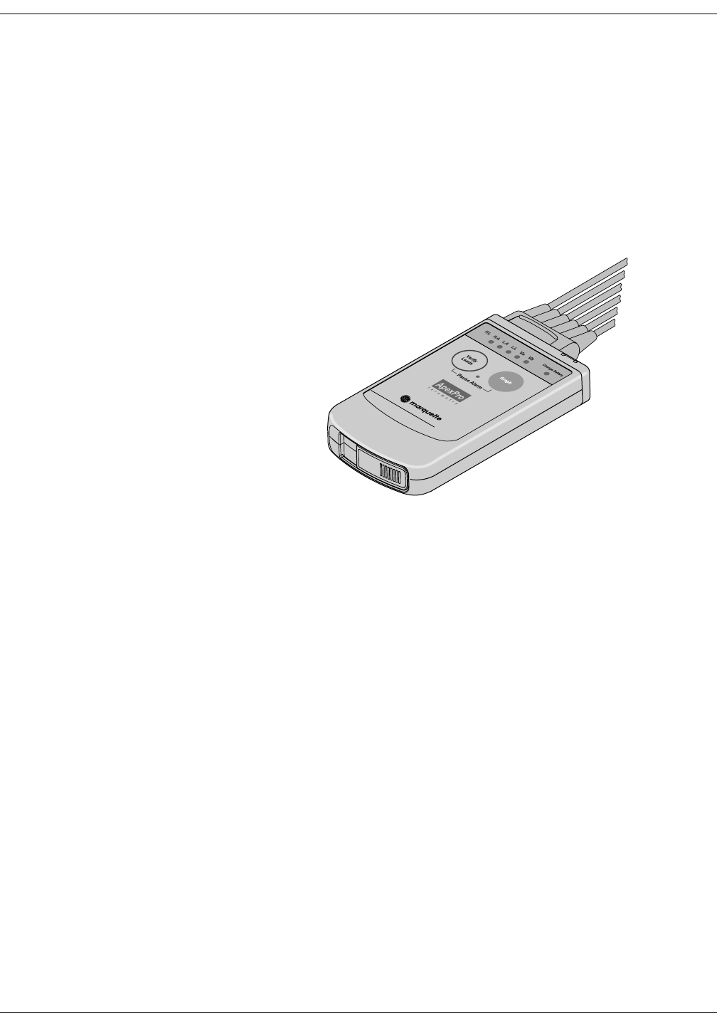
ApexPro Transmitter
The ApexPro transmitter sends the patient’s ECG data to the ApexPro
receiver subsystem for processing. Data is then transmitted via a
dedicated Ethernet interface to the clinical information center for further
processing and viewing.
Additionally, the ApexPro transmitter can send the patient’s SpO2 and
noninvasive blood pressure data when the optional Apex Oximeter and/
or Accutracker DX noninvasive blood pressure monitor are connected to
it.
ApexPro Transmitter
309B
3-6 ApexPro Telemetry System Revision A
2001989-002
Equipment Overview: ApexPro Telemetry System
ApexPro Transmitter Buttons and LEDs
Verify Leads
Pressing the Verify Leads button enables the good lead LEDs. After
this button is pressed, the LEDs for good leads are illuminated for one
minute.
Graph
Pressing the Graph button initiates a 20-second graph strip to be
printed on the writer or printer.
When an IMPACT.wf paging system (version II or later) is also available
in the same care unit, pressing the Graph button enables the View on
Demand feature (also called the Apex Graph Button Push feature). The
IMPACT.wf server generates a manually initiated sample page or
snapshot of the patient’s ECG waveform and any other enabled/
monitored non-arrhythmia parameters.
When you press the Graph button on the ApexPro transmitter, it
generates both an IMPACT.wf update as well as a standard ECG
waveform graph at the clinical information center. The IMPACT.wf
update is labeled “Sample” when this data is displayed on the
IMPACT.wf receiver and stored in history. Additionally, all receivers
assigned to the patient receive an update/sample.
Verify Leads – Checks
the lead/skin preparation
quality.
Graph – Initiates
the printing of a
graph strip.
Pause Alarm LED
Good lead LEDs
Change
Battery LED
Dust covers

Revision A ApexPro Telemetry System 3-7
2001989-002
Equipment Overview: ApexPro Telemetry System
Dust Covers
The ApexPro transmitter has two dust covers, used when the INTFC
(interface) connectors are not being utilized.
:$51,1*
DUST COVERS — If the dust covers for the INTFC
(interface) connectors become detached from the ApexPro
transmitter, they may pose a choking hazard for
pediatric patients. Inspect the dust covers before each
use to verify that they are securely attached. If the dust
covers become detached and cannot be reinserted into
their retaining slot, do not use them on the ApexPro
transmitter, and keep them out of pediatric patients’
reach.
Pausing Alarms
Refer to Chapter 8, Alarm Control, for important information regarding
transmitter alarm pause, alarm pause breakthrough, and the Enable
Transmitter Pause option.
The Enable Transmitter Pause option for a telemetry patient admitted to
the clinical information center must be activated before the patient can
initiate an alarm pause from the transmitter.
To pause the alarms for five minutes, press both transmitter buttons
simultaneously. The Pause Alarm LED flashes. “ALARM PAUSE” is
also displayed in the patient’s waveform window on the clinical
information center screen. After five minutes, the LED on the
transmitter will no longer flash and alarms will be reactivated.
:$51,1*
Alarms do not sound and alarm graphs do not print
during an “ALARM PAUSE” condition.
Reactivating Alarms
To reactivate the alarms before the five minute time period has elapsed,
press both transmitter buttons simultaneously again.
Low Batteries
The Change Battery LED flashes when battery power is running low.
Change the batteries in the ApexPro transmitter when this LED flashes.
Refer to the ApexPro Transmitter Battery Installation section in Chapter
4, Connection, for more information about changing the batteries.
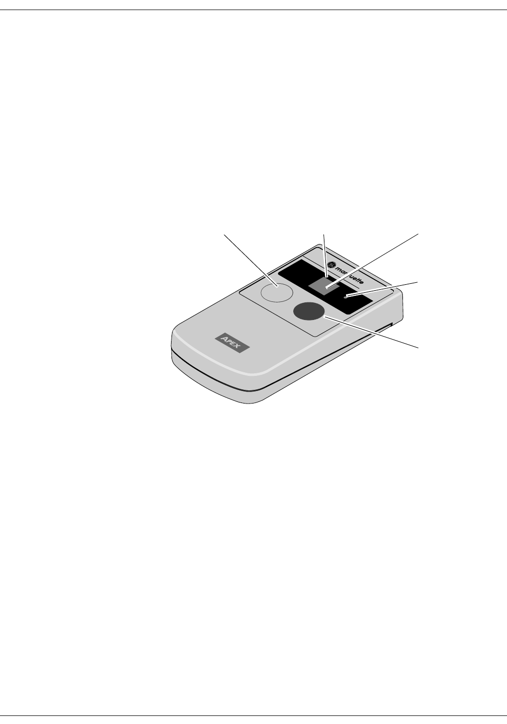
3-8 ApexPro Telemetry System Revision A
2001989-002
Equipment Overview: ApexPro Telemetry System
Apex Oximeter SpO2 Module
The Apex Oximeter is an optional module that can be connected to the
ApexPro transmitter, allowing telemetry monitoring of a patient’s pulse
oximetry data. The Apex Oximeter must be connected to an ApexPro
transmitter in order to convey SpO2 data to the clinical information
center. Only digital data is available; no waveforms are generated or
transmitted. Digital data is stored in Graphic Trends and Vital Signs on
the CIC, and it is also displayed on the Apex Oximeter.
127(SpO2 and SPO2 are used interchangeably throughout this manual.
Apex Oximeter Buttons and LEDs
Pressing the Power button turns on the battery power to the Apex
Oximeter. The digital display also turns on for one minute. After one
minute, the display will turn off, but power to the Apex Oximeter
remains on. This is indicated by the flashing Power LED (horizontal bar).
When display power is off (flashing Power LED), pressing the Display
On/Off button turns the display on for one minute. After one minute the
display turns off, but power to the Apex Oximeter remains on, indicated
by the flashing Power LED.
To turn the display on continuously, press and hold the Display On/Off
button for 2 seconds. The flashing Power LED turns off to verify that the
display has been turned on in continuous mode. To turn the display off at
any time, press the Display On/Off button again.
127(Using the Apex Oximeter with the display on continuously will
result in reduced battery life.
To turn all power to the Apex Oximeter off, press and hold the Power
button for 2 seconds.
The Perfusion LED indicates the strength of the patient’s SPO2 signal.
For more information, refer to Chapter 12, SpO2 Monitoring.
Power LED — When power is
on, an indicator flashes here.
Power Display
On/Off
Pulse Rate
SpO %
2
Perfusion
oximeter
310B
Perfusion LED
Display On/Off —
Turns the oximeter
display on and off.
Power — Turns
power on and off. Digital display
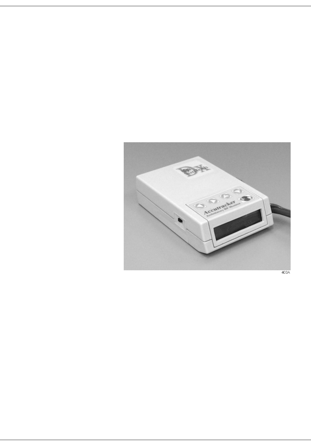
Revision A ApexPro Telemetry System 3-9
2001989-002
Equipment Overview: ApexPro Telemetry System
Accutracker DX Noninvasive Blood Pressure (NBP) Monitor
127(The Accutracker DX noninvasive blood pressure monitor is
available in the United States only. This model, available from
GE Marquette, has been modified by SunTech Medical
Instruments to operate with the ApexPro telemetry system.
The Accutracker DX noninvasive blood pressure monitor is an optional
module that can be connected to the ApexPro transmitter, allowing
telemetry monitoring of a patient’s NBP data. The blood pressure cuff is
connected to the blood pressure monitor, which measures and displays
systolic and diastolic blood pressures using the auscultatory method.
When the blood pressure monitor is connected to an ApexPro
transmitter, digital values are also displayed at the clinical information
center, and stored in Graphic Trends and Vital Signs on the CIC.
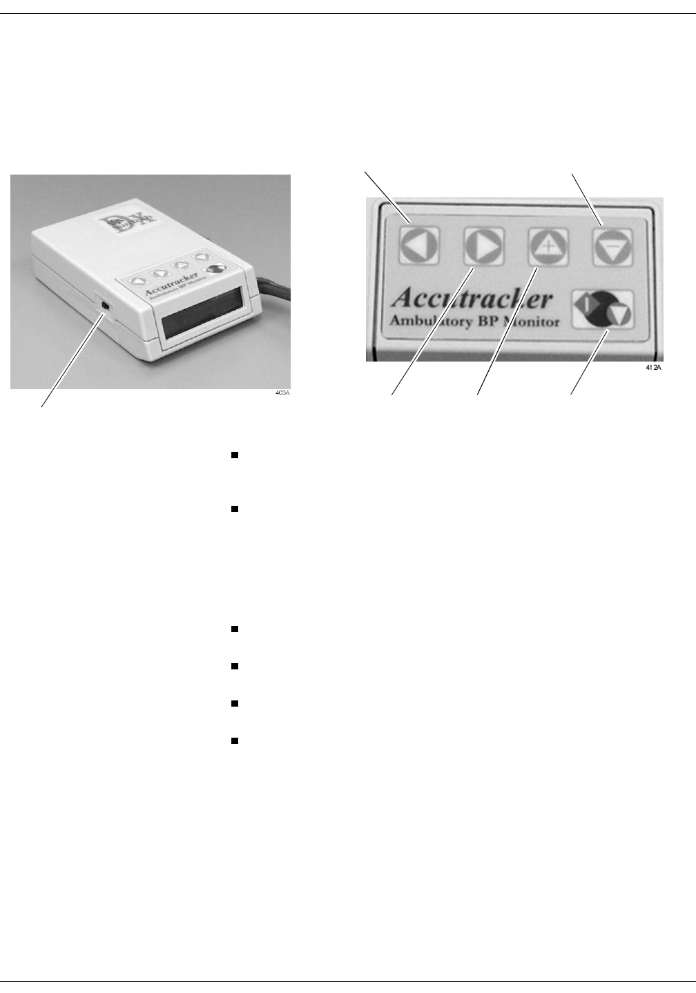
3-10 ApexPro Telemetry System Revision A
2001989-002
Equipment Overview: ApexPro Telemetry System
Accutracker DX Buttons and Switches
An on/off switch and five buttons control the functions of the blood
pressure monitor. Their functions are described below.
The on/off switch, labeled 1/0, is located on the side of the blood
pressure monitor. The on position is 1; the off position is 0. It is used
to turn the main power on and off.
The START/STOP button starts and stops blood pressure readings.
During the monitoring period, it can be used by the patient at the
clinician’s discretion. Pressing the START/STOP button once while
a patient is being monitored “wakes up” the blood pressure monitor
from sleep mode and offers the options to change the measurement
interval, view the time left until the next measurement, or perform a
manual reading by pressing the START/STOP button a second time.
The NEXT button moves forward to the next menu item on the blood
pressure monitor display.
The LAST button moves back to the previous menu item on the blood
pressure monitor display.
The YES + button allows a yes response to a question or an increase
in the value shown on the blood pressure monitor display.
The NO – button allows a no response to a question or a decrease in
the value shown on the blood pressure monitor display.
Refer to Chapter 13, NBP Monitoring, for more information about
Accutracker DX operation.
On/Off
switch
YES +
button START/STOP
button
NEXT
button
NO –
button
LAST
button
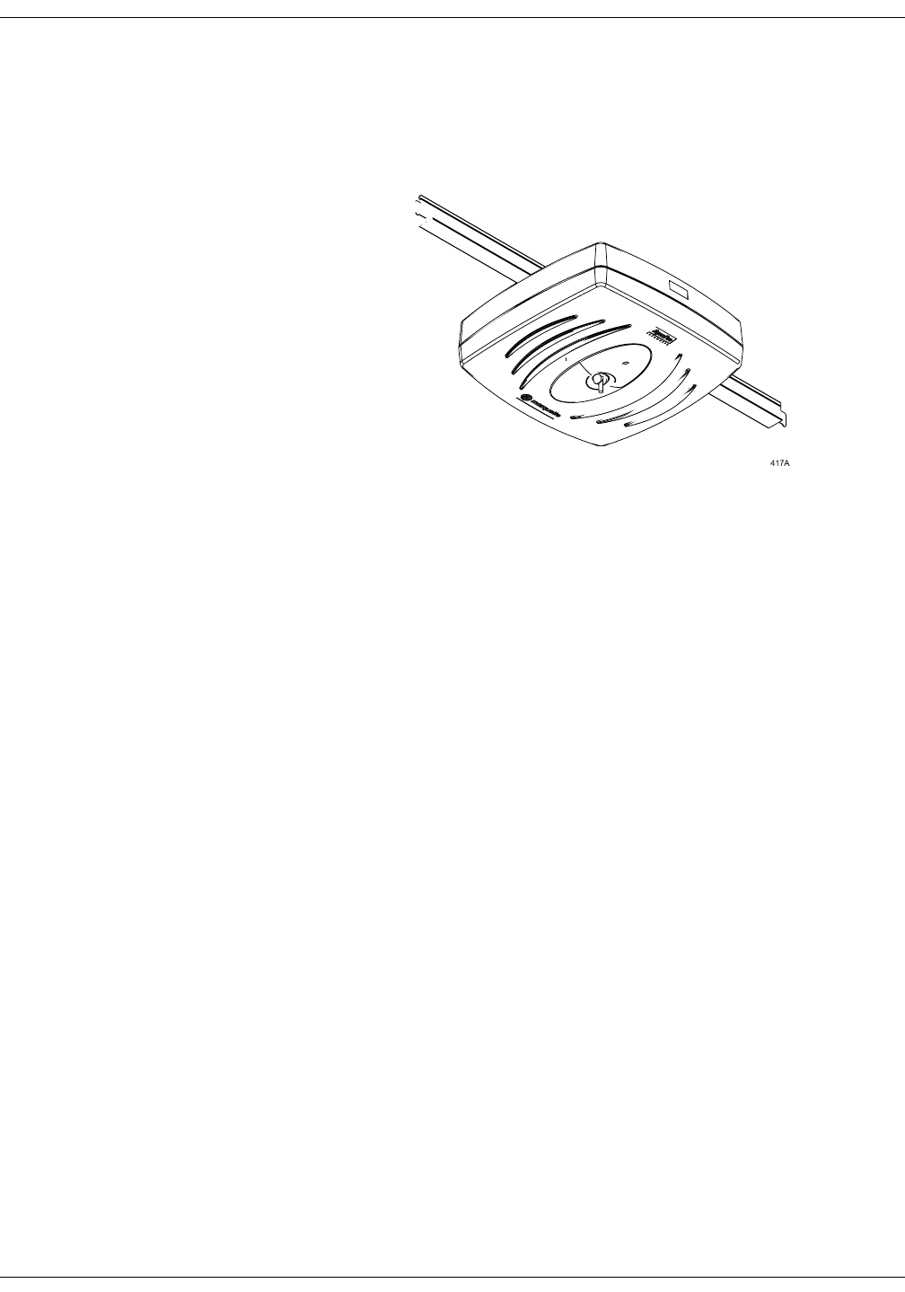
Revision A ApexPro Telemetry System 3-11
2001989-002
Equipment Overview: ApexPro Telemetry System
Antenna System
The antenna system is used for transmission of data from the
transmitter to the receiver system. An ApexPro receiver antenna is
illustrated below.
Receiver System
Each receiver in the quad receiver module, located in the receiver
subsystem, receives data from the transmitters. This data is processed
by the receiver system and then transmitted via the dedicated Ethernet
interface to a clinical information center for further processing and
display. The quad receivers and the receiver subsystem together are
known as the receiver system.
Unity Network
The Unity network is GE Marquette’s information network system, used
to transmit information from one GE Marquette product to others
connected to the same Unity network.
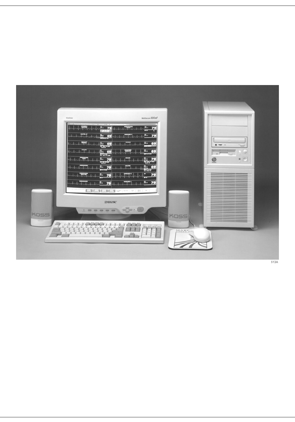
3-12 ApexPro Telemetry System Revision A
2001989-002
Equipment Overview: ApexPro Telemetry System
Clinical Information Center
The Clinical Information Center is the central station that displays
ApexPro telemetry system data sent to it via the dedicated Ethernet
interface. The clinical information center also allows modification of
telemetry defaults and setup information, among other telemetry
functions.

Revision A ApexPro Telemetry System 4-1
2001989-002
4Connection
ApexPro Transmitter Setup . . . . . . . . . . . . . . . . . . . . . . . . . . . . . . . . . . . . . . . . . . . 4-3
ApexPro Transmitter Battery Installation . . . . . . . . . . . . . . . . . . . . . . . . . . . . . . . .4-3
Battery Functional Life . . . . . . . . . . . . . . . . . . . . . . . . . . . . . . . . . . . . . . . . . . . . . .4-3
ApexPro Transmitter Leadwires . . . . . . . . . . . . . . . . . . . . . . . . . . . . . . . . . . . . . . 4-4
Installation . . . . . . . . . . . . . . . . . . . . . . . . . . . . . . . . . . . . . . . . . . . . . . . . . . .4-4
Disconnection from the Transmitter . . . . . . . . . . . . . . . . . . . . . . . . . . . . . . . .4-4
Multi-Link Leadwire Sets . . . . . . . . . . . . . . . . . . . . . . . . . . . . . . . . . . . . . . . .4-5
Attachment to the Electrodes . . . . . . . . . . . . . . . . . . . . . . . . . . . . . . . . . . . . .4-5
Apex Oximeter Setup . . . . . . . . . . . . . . . . . . . . . . . . . . . . . . . . . . . . . . . . . . . . . . . . 4-6
Apex Oximeter Battery Installation . . . . . . . . . . . . . . . . . . . . . . . . . . . . . . . . . . . . .4-6
Battery Functional Life . . . . . . . . . . . . . . . . . . . . . . . . . . . . . . . . . . . . . . . . . . . . . .4-6
Apex Oximeter Connections . . . . . . . . . . . . . . . . . . . . . . . . . . . . . . . . . . . . . . . . 4-7
SpO2 Probe Connection . . . . . . . . . . . . . . . . . . . . . . . . . . . . . . . . . . . . . . . .4-7
Connection to the ApexPro Transmitter . . . . . . . . . . . . . . . . . . . . . . . . . . . . .4-7
Accutracker DX Setup . . . . . . . . . . . . . . . . . . . . . . . . . . . . . . . . . . . . . . . . . . . . . . . . 4-8
Tips for Monitoring . . . . . . . . . . . . . . . . . . . . . . . . . . . . . . . . . . . . . . . . . . . . . . . . .4-8
Battery Installation . . . . . . . . . . . . . . . . . . . . . . . . . . . . . . . . . . . . . . . . . . . . . . . . .4-8
Accutracker DX Functional Life . . . . . . . . . . . . . . . . . . . . . . . . . . . . . . . . . . . . . . 4-9
Accutracker DX Connections . . . . . . . . . . . . . . . . . . . . . . . . . . . . . . . . . . . . . . . 4-10
Interconnection Cables . . . . . . . . . . . . . . . . . . . . . . . . . . . . . . . . . . . . . . . . . . . . . . 4-13


Revision A ApexPro Telemetry System 4-3
2001989-002
Connection: ApexPro Transmitter Setup
ApexPro Transmitter Setup
ApexPro Transmitter Battery Installation
Install two new AA alkaline batteries in the transmitter.
1. Locate the battery cover at the bottom of the transmitter.
2. Slide the cover over to open the battery compartment.
3. Insert the batteries, being careful to follow the polarity signs
embossed on the lower back side of the transmitter.
4. Close the battery cover.
127(When the Change Battery LED starts flashing, the ApexPro
transmitter has approximately one hour of reserve power before
the unit shuts down.
Battery Functional Life
The ApexPro transmitter runs on two AA batteries. Battery life is
approximately 40 hours.
For optimum performance, follow these guidelines:
Install two new alkaline batteries each time you begin monitoring a
new patient.
Install two new alkaline batteries whenever the Change Battery
LED on the ApexPro transmitter is flashing.
Do not use rechargeable batteries.
Always change both batteries at the same time.
Always use new batteries.
&$87,21
GE Marquette Medical Systems recommends that you
always replace both batteries at the same time. Re-using
old batteries or using a combination of old and new
batteries in the ApexPro transmitter will compromise
functionality of the transmitter and increase the risk of
fire hazard.
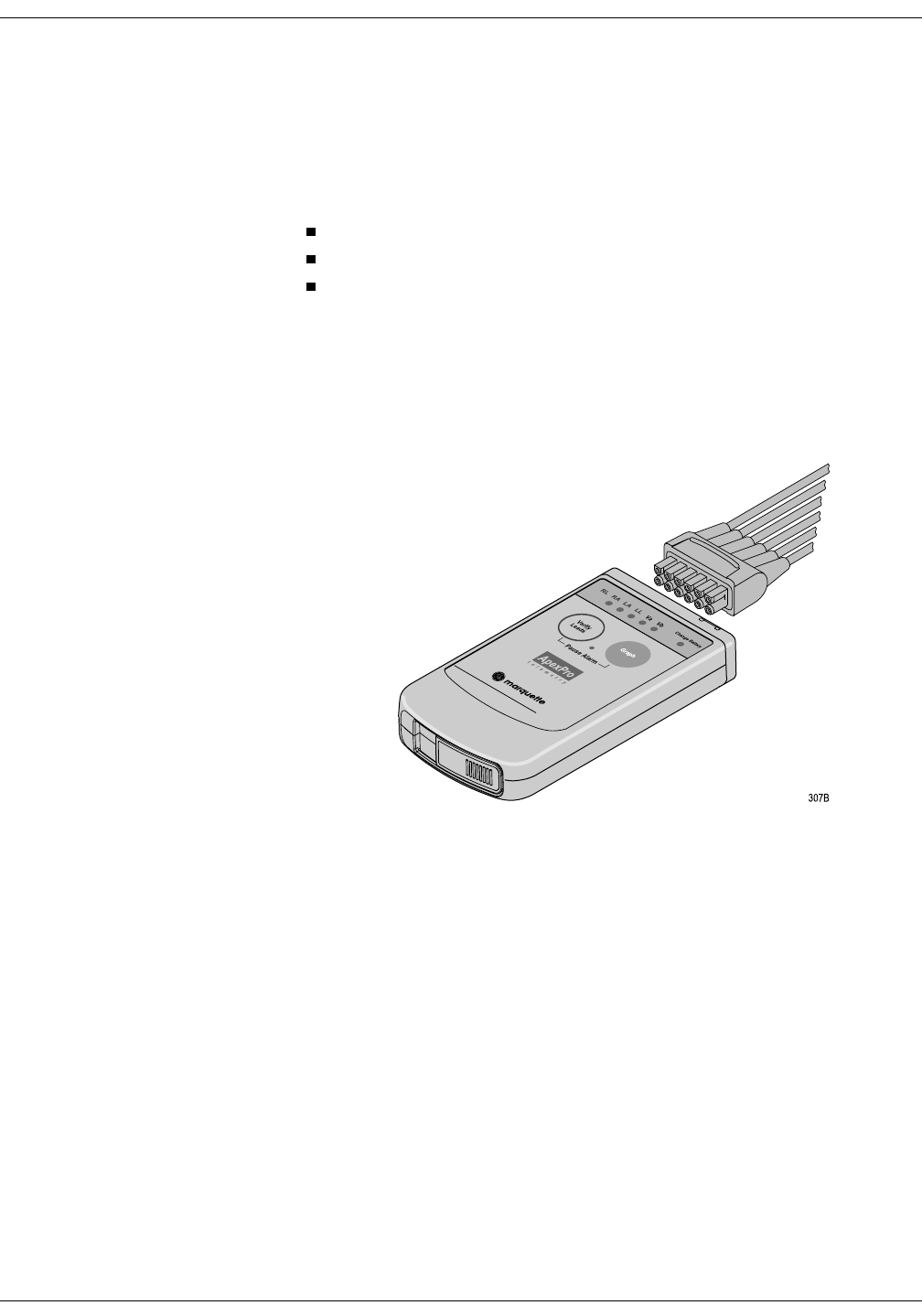
4-4 ApexPro Telemetry System Revision A
2001989-002
Connection: ApexPro Transmitter Setup
ApexPro Transmitter Leadwires
Installation
The ApexPro transmitter can be used with the following Multi-Link
leadwire sets:
Multi-Link six-leadwire set
Multi-Link five-leadwire set
Multi-Link three-leadwire set
127(Although the Multi-Link three-leadwire set is no longer
manufactured, existing sets will function with the ApexPro
transmitter.
To install a leadwire set into the ApexPro transmitter, align the leadwire
pins with the connector on the top of the transmitter, then push the
leadwire set firmly into the transmitter.
Disconnection from the Transmitter
To disconnect the leadwires from the ApexPro transmitter, grasp the
molded end or the combiner firmly and pull away from the transmitter.

Revision A ApexPro Telemetry System 4-5
2001989-002
Connection: ApexPro Transmitter Setup
Multi-Link Leadwire Sets To use sets of Multi-Link individual leadwires, firmly press the
individual leadwires into their appropriate locations on the combiner.
Use the colors on the leadwires to place them in corresponding order with
the colors that appear on the back of the ApexPro transmitter.
Attachment to the Electrodes
1. Attach leadwires to the transmitter by plugging the Multi-Link
leadwire set into the transmitter.
2. Attach leadwire clip to the terminal on the electrodes. Take care to
attach the color-coded clips to the corresponding electrode locations.
3. Loop the leadwires and secure them to the patient with tape. Stress
loops prevent the connection to the electrode from being loosened or
pulled apart as the patient moves.
127(Do not tape across the electrode.
Individual leadwires
Combiner

4-6 ApexPro Telemetry System Revision A
2001989-002
Connection: Apex Oximeter Setup
Apex Oximeter Setup
Apex Oximeter Battery Installation
Install two new AA alkaline batteries in the Apex Oximeter:
1. Locate the battery cover at the bottom of the back of the Apex
Oximeter.
2. Press the latch tab and lift up to open the battery compartment.
3. Insert the batteries, being careful to follow the polarity signs located
within the battery compartment.
4. Close the battery cover.
127(When the digital displays on the Apex Oximeter start flashing,
the Apex Oximeter has approximately one hour of reserve power
left before the unit shuts down.
Battery Functional Life
The Apex Oximeter runs on two AA batteries. Battery life is
approximately 60 hours.
For optimum performance, follow these guidelines:
Install two new alkaline batteries each time you begin monitoring a
new patient.
Install two new alkaline batteries whenever the digital displays on
the Apex Oximeter start flashing.
Always change both batteries at the same time.
Always use new batteries.
&$87,21
GE Marquette Medical Systems recommends that you
always replace both batteries at the same time. Re-using
old batteries or using a combination of old and new
batteries in the Apex Oximeter will compromise
functionality of the transmitter and increase the risk of
fire hazard.

Revision A ApexPro Telemetry System 4-7
2001989-002
Connection: Apex Oximeter Setup
Apex Oximeter Connections
To function correctly, the Apex Oximeter must be connected to a pulse
oximetry (SpO2) probe. To transmit data to the clinical information
center, the Apex Oximeter must also be connected to the ApexPro
transmitter.
SpO2 Probe Connection Connect the SpO2 probe to the Apex Oximeter by plugging the non-
sensor end of the probe into the 9-pin connector on the top of the Apex
Oximeter.
&$87,21
Use only Nonin SpO2 probes with the Apex Oximeter.
The reliability of SpO2 data obtained with any other
probe has not been verified.
Connection to the ApexPro Transmitter
Connect the Apex Oximeter to the ApexPro transmitter by using the
interconnection cable supplied with the Apex Oximeter.
127(Refer to the Interconnection Cables section in this chapter for
information about cable compatibility.
Plug one end of the interconnection cable into the 5-pin connector labeled
INTFC (interface) on the Apex Oximeter. Plug the other end into one of
the 5-pin connectors labeled INTFC on the ApexPro telemetry
transmitter.
When properly interconnected, the Apex Oximeter and the ApexPro
transmitter should appear similar to the illustration below.
The Apex Oximeter and the ApexPro transmitter can now be attached to
the patient. Follow your unit’s protocol for attaching them to the patient.
A common method is to place them back-to-back in the same pouch and
belt them on the patient.
Power Display
On/Off
Pulse Rate
SpO %
2
Perfusion
oximeter
400B
INTFC connector INTFC connector
Interconnection
cable

4-8 ApexPro Telemetry System Revision A
2001989-002
Connection: Accutracker DX Setup
Accutracker DX Setup
127(The Accutracker DX noninvasive blood pressure monitor is
available in the United States only.
Tips for Monitoring
Use a microphone pad to maintain the best microphone position.
Use a cuff anchor to maintain the blood pressure cuff’s position.
Advise the patient not to shower or bathe while being monitored.
Battery Installation
Install four new AA alkaline batteries in the Accutracker DX blood
pressure monitor. Follow these steps:
1. Locate the battery cover on the back of the blood pressure monitor.
2. Press down and gently slide off the cover.
3. Remove the old batteries by lifting up on the ribbon in the battery
case. Dispose of the old batteries properly, following your local
ordinances.
4. Insert the new batteries, being careful to follow the polarity signs. Be
sure to place the batteries on top of the ribbon.
5. Slide the battery cover back on securely.
127(Change the batteries in the blood pressure monitor when the
message “Low Batt” appears on the Accutracker display.

Revision A ApexPro Telemetry System 4-9
2001989-002
Connection: Accutracker DX Setup
Accutracker DX Functional Life
IMPORTANT — Store and use the Accutracker DX blood pressure
monitor with four good AA batteries installed.
The four AA batteries will last for approximately 250 blood pressure
readings, taken at an average interval of 15 minutes.
Install four new alkaline batteries each time you begin monitoring a
patient.
The Accutracker DX blood pressure monitor contains an internal lithium
battery capable of sustaining the Accutracker for a maximum of 9
months (6400 hours) without AA batteries installed. If the lithium
battery becomes fully discharged, the Accutracker must be returned to
the factory for service. To extend the life of the lithium battery, always
store the Accutracker DX with four good AA batteries installed.
127(This is a cumulative 9-month period, spanning the entire life of
the blood pressure monitor.
If the lithium battery is completely drained, the unit will not function.
The internal lithium battery is not user replaceable. The unit must be
returned for service if the lithium battery needs to be replaced.
It is recommended that the lithium battery be serviced every three to five
years.
Store and use the Accutracker DX blood pressure monitor with four good
AA batteries installed. For long-term storage, install new batteries and
replace them every four months.
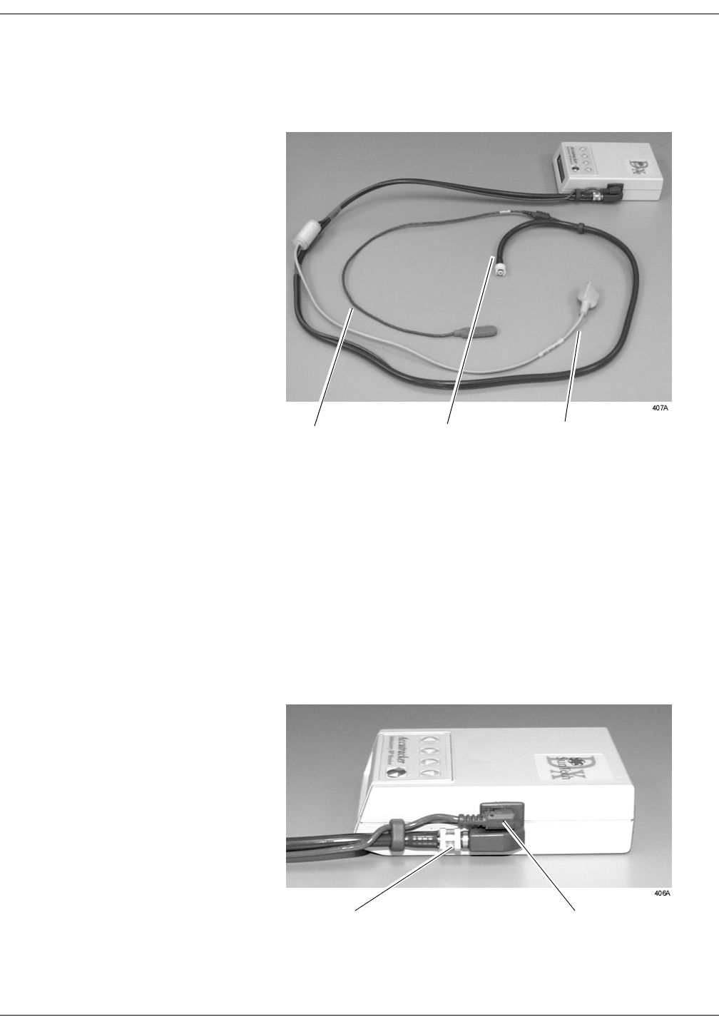
4-10 ApexPro Telemetry System Revision A
2001989-002
Connection: Accutracker DX Setup
Accutracker DX Connections
The patient cable, microphone cable, and interconnection cable are
attached to one another in one assembly. Refer to the illustration below.
127(Refer to the Interconnection Cables section in this chapter for
information about cable compatibility.
If the patient cable/microphone cable/interconnection cable assembly is
not already connected to the Accutracker DX noninvasive blood pressure
monitor, follow this procedure to connect it:
1. Attach the brass end of the patient cable to the blood pressure
monitor by screwing it onto the brass air hose connector on the side
of the blood pressure monitor.
2. Connect the microphone cable to the blood pressure monitor by
plugging it into the 6-pin connector on the side of the blood pressure
monitor, near the air hose connector.
Patient CableMicrophone Cable Interconnection Cable
Patient Cable
Connection Microphone Cable
Connection
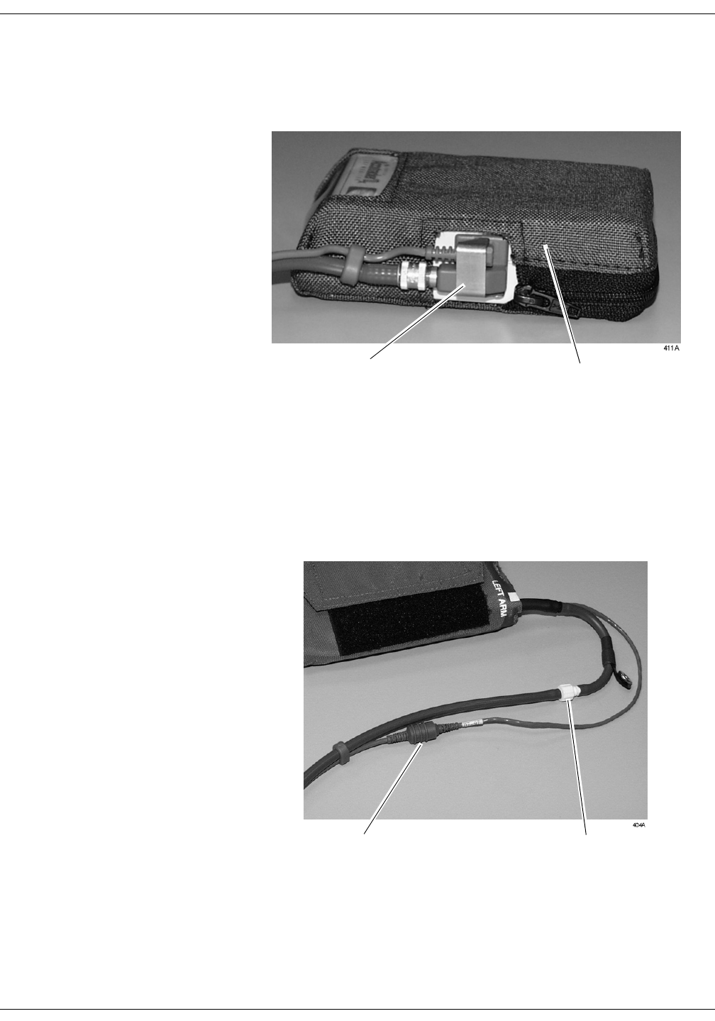
Revision A ApexPro Telemetry System 4-11
2001989-002
Connection: Accutracker DX Setup
3. Secure the cable by screwing on the metal cable cap, then insert the
blood pressure monitor into the nylon pouch. When the patient cable
assembly is connected, the blood pressure monitor will look similar to
the following photograph.
Completed Patient Cable Assembly Connection
4. Attach the blood pressure cuff hose to the patient cable already
attached to the blood pressure monitor. Insert the cuff hose into the
white plastic fitting on the patient cable. Turn the fitting to the right
approximately one quarter turn. Some connector models will click
when they are connected, otherwise, be sure that it is securely
tightened. Then plug the 3-pin microphone connector into 3-pin
connector on the microphone cable.
Blood Pressure Cuff Connections
Cable Cap Nylon Pouch
Cuff Hose Connection
Microphone Connection

4-12 ApexPro Telemetry System Revision A
2001989-002
Connection: Accutracker DX Setup
5. Connect the 5-pin end of the interface cable to one of the 5-pin port
labeled INTFC (interface) on the top of the ApexPro transmitter. The
interface cable is already connected to the blood pressure monitor
because it is a branch of the patient cable. Ensure that the ApexPro
transmitter’s patient leadwires are properly connected. The
leadwires must be connected for telemetry transmission of NBP data.
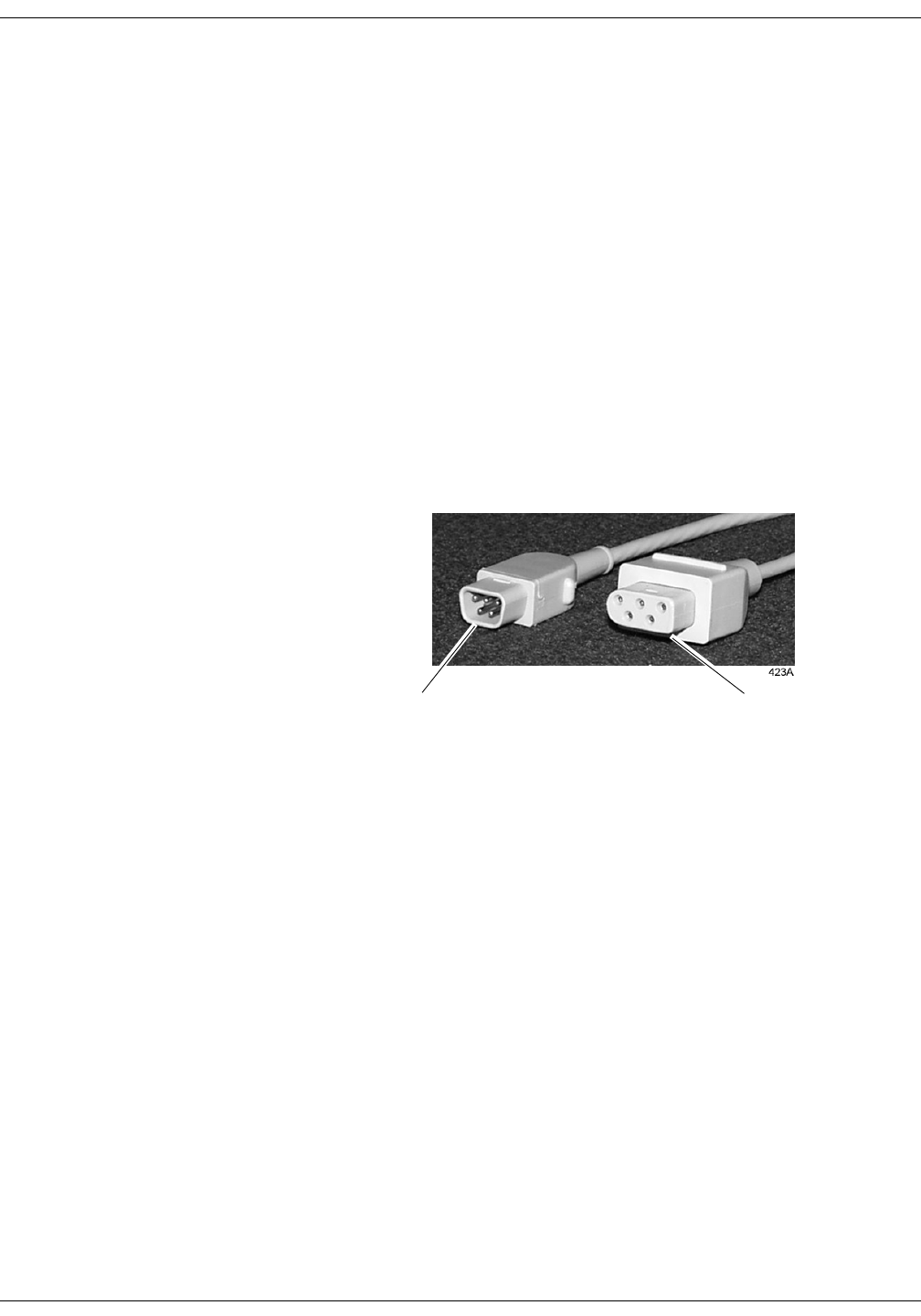
Revision A ApexPro Telemetry System 4-13
2001989-002
Connection: Interconnection Cables
Interconnection Cables
The interconnection cables used to connect the ApexPro transmitter with
the Apex Oximeter and/or the Accutracker DX blood pressure monitor
are not the same as those used with the Apex S transmitter (CD
Telemetry-LAN monitoring system).
127(The Accutracker DX noninvasive blood pressure monitor is
available in the United States only.
The connector ends that are plugged into the telemetry transmitters are
different and are not interchangeable.
Be sure to use the correct interconnection cable when you connect the
Apex Oximeter or Accutracker DX blood pressure monitor to the ApexPro
transmitter.
The figure below illustrates the difference in connector ends for each
system.
ApexPro telemetry system
interconnection cable connector —
plugs into the ApexPro transmitter.
CD Telemetry-LAN monitoring
system interconnection cable
connector — plugs into the
Apex S transmitter.

4-14 ApexPro Telemetry System Revision A
2001989-002
Connection: Interconnection Cables
For your notes

Revision A ApexPro Telemetry System 5-1
2001989-002
5Maintenance
Biocompatibility . . . . . . . . . . . . . . . . . . . . . . . . . . . . . . . . . . . . . . . . . . . . . . . . . . . . . 5-3
Inspection . . . . . . . . . . . . . . . . . . . . . . . . . . . . . . . . . . . . . . . . . . . . . . . . . . . . . . . . . . 5-4
General Cleaning . . . . . . . . . . . . . . . . . . . . . . . . . . . . . . . . . . . . . . . . . . . . . . . . . . . . 5-5
Cleaning the Transmitters . . . . . . . . . . . . . . . . . . . . . . . . . . . . . . . . . . . . . . . . . . . . 5-6
Cleaning the Leadwires . . . . . . . . . . . . . . . . . . . . . . . . . . . . . . . . . . . . . . . . . . . . . . . 5-7
Cleaning the Power Unit . . . . . . . . . . . . . . . . . . . . . . . . . . . . . . . . . . . . . . . . . . . . . . 5-8
Transmitter and Leadwire Storage . . . . . . . . . . . . . . . . . . . . . . . . . . . . . . . . . . . . . . 5-9
Transmitter Holder . . . . . . . . . . . . . . . . . . . . . . . . . . . . . . . . . . . . . . . . . . . . . . . . .5-9
Storage Guidelines . . . . . . . . . . . . . . . . . . . . . . . . . . . . . . . . . . . . . . . . . . . . . . . .5-9
Technical Maintenance . . . . . . . . . . . . . . . . . . . . . . . . . . . . . . . . . . . . . . . . . . . . . . 5-10


Revision A ApexPro Telemetry System 5-3
2001989-002
Maintenance: Biocompatibility
Biocompatibility
When used as intended, the parts of the product described in this
operator manual, including accessories that come in contact with the
patient during the intended use, fulfill the biocompatibility requirements
of the applicable standards. If you have questions about this matter,
please contact GE Marquette Medical Systems or its representatives.

5-4 ApexPro Telemetry System Revision A
2001989-002
Maintenance: Inspection
Inspection
An effective maintenance schedule should be established for your
monitoring equipment and reusable supplies. This should include
inspection as well as general cleaning on a regular basis. The
maintenance schedule must comply with the policies of your institution’s
infection control unit and/or biomedical department.
&$87,21
Failure on the part of the responsible hospital or
institution employing the use of this monitoring
equipment to implement a satisfactory maintenance
schedule may cause undue equipment failure and
possible health hazards.
Check with your biomedical department to be sure preventive
maintenance and calibration have been done. The service manuals
contain detailed information.
Follow these guidelines when inspecting the equipment:
Inspect the equipment for obvious physical damage and replace
damaged items.
Inspect all cords for fraying or other damage. Inspect all plugs and
connectors for bent prongs or pins. Repair or replacement must be
performed by qualified service personnel.
Inspect all cable insulation. Qualified service personnel should repair
or replace damaged or deteriorated cables.
In the United States, GE Marquette Service is available 24-hours a day
by calling 800-558-7044.
Outside the United States, please contact your sales/service office.
127(Refer to the service manuals for more comprehensive checkout
procedures.

Revision A ApexPro Telemetry System 5-5
2001989-002
Maintenance: General Cleaning
General Cleaning
:$51,1*
Disconnect AC-powered equipment from the power line
before cleaning or disinfecting its surface. Turn off the
power to battery-powered equipment before cleaning or
disinfecting its surface.
The equipment should be cleaned on a regular basis. (Comply with the
policies of your institution’s infection control unit and/or biomed
department.) The exterior surfaces of the equipment may be cleaned with
a dampened, lint-free cloth. Use one of the following approved solutions:
ammonia (diluted)
Cidex
sodium hypochlorite bleach (diluted)
127(Severe corrosion may occur to any metal parts that come in
contact with bleach. Do not submerge patient cable ends or
leadwire ends.
mild soap (diluted)
To avoid damage to the equipment, follow these rules:
&$87,21
Failure to follow these rules may melt, distort, or dull the
finish of the case, blur lettering on the labels, or cause
equipment failures.
Always dilute the solutions according to the manufacturer’s
suggestions.
Always wipe off all the cleaning solution with a dry cloth after
cleaning.
Never use a cleaning substance containing wax.
Never pour or spray water or any cleaning solution on the
equipment.
Never permit fluids to run behind switches, into the connectors, or
into any ventilation openings in the equipment.
Never use these cleaning agents:
abrasive cleaners or solvents of any kind,
acetone,
ketone,
alcohol-based cleaning agents, or
Betadine

5-6 ApexPro Telemetry System Revision A
2001989-002
Maintenance: Cleaning the Transmitters
Cleaning the Transmitters
These cleaning instructions apply to the ApexPro transmitter, the Apex
Oximeter, and the Accutracker DX blood pressure monitor.
&$87,21
Do not autoclave the transmitters.
For general cleaning, wiping with mild soap and water and wiping dry is
recommended.
For more intensive disinfecting or sterilization:
Aqueous disinfectants such as glutaraldehydes (Sporicidin, etc.), 2-
part sodium chloride/lactic acid mixture (i.e., Exspor and other
chlorine dioxide action types), and other cold cleaning agents are
acceptable. These solutions may shorten the transmitter’s useful
lifetime after repeated applications.
Ethylene Oxide (ETO) is acceptable but may discolor and/or reduce
the useful lifetime of the transmitter.
&$87,21
The decision to sterilize must be made per your
institution’s requirements with an awareness of the
effect on the integrity of the transmitter.
Do not submerse the transmitters.

Revision A ApexPro Telemetry System 5-7
2001989-002
Maintenance: Cleaning the Leadwires
Cleaning the Leadwires
&$87,21
Do not use acetone or ketone solvents for cleaning; do not
use an autoclave or steam cleaner.
For general cleaning, wipe with a lint-free cloth dampened with mild
soap and water. Drying off excess cleaning solution is recommended.
Leadwires should hang freely when wiping. Leadwires can be cleaned
with isopropyl alcohol wipes. For more intensive disinfecting or
sterilization:
Aqueous disinfectants such as glutaraldehydes (Sporicidin, etc.), 2-
part sodium chloride/lactic acid mixture (i.e., Exspor and other
chlorine dioxide action types), and other cold cleaning agents are
acceptable. These solutions may shorten the leadwire’s useful
lifetime after repeated applications.
Ethylene Oxide (ETO) is acceptable but may discolor and/or reduce
the useful lifetime of the leadwire.
&$87,21
The decision to sterilize must be made per your
institution’s requirements with an awareness of the
effect on the integrity of the leadwire.
Do not submerse telemetry leadwires.

5-8 ApexPro Telemetry System Revision A
2001989-002
Maintenance: Cleaning the Power Unit
Cleaning the Power Unit
Follow these precautions when cleaning the power unit connected to the
antenna system.
:$51,1*
When cleaning the power unit, use a cloth dampened
with cleaning alcohol on the outside of the enclosure only.
Do not immerse the product in water or a safety hazard
could arise during use.
Periodic leakage current testing should be done on the combined power
supply and end-use system on a yearly basis when used in a hospital
environment where such test equipment is commonly available.
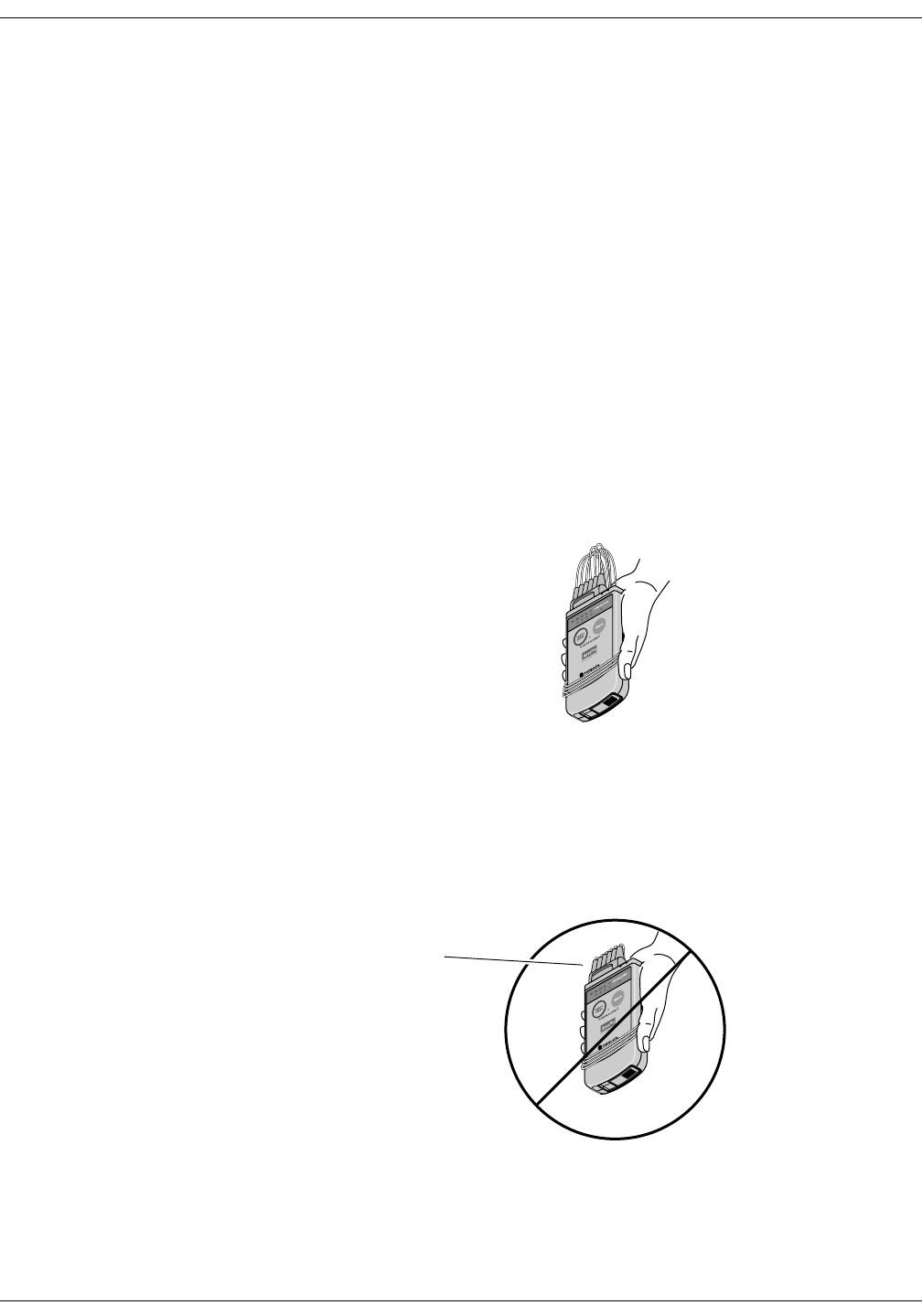
Revision A ApexPro Telemetry System 5-9
2001989-002
Maintenance: Transmitter and Leadwire Storage
Transmitter and Leadwire Storage
Transmitter Holder
It is recommended that you store the transmitter and leadwires in the
optional transmitter holder (not pictured). This wall-mounted holder can
store up to six ApexPro transmitters. The leadwires hang freely below
the holder, minimizing the possibility of damage.
Storage Guidelines
If a transmitter holder is not available, follow these guidelines for
storage.
Correct Storage
Wrap the leadwires around the transmitter, allowing the top of the
leadwires to remain loose. Leadwires should not be stretched tightly
during storage.
Incorrect Storage
Do not bend or stretch leadwires tightly before wrapping around the
transmitter. Improper storage will cause damage and shorten the
leadwires’ useful lifetime.
315B
314B
Tightly Wrapped

5-10 ApexPro Telemetry System Revision A
2001989-002
Maintenance: Technical Maintenance
Technical Maintenance
Schematic diagrams and other relevant technical information can be
found in the service manuals supplied with this equipment. Comply with
the policies of your institution’s biomedical department, or the
recommendations made within the Preventive Maintenance section of
the product’s service manual.

Revision A ApexPro Telemetry System 6-1
2001989-002
6Telemetry Setup
Introduction . . . . . . . . . . . . . . . . . . . . . . . . . . . . . . . . . . . . . . . . . . . . . . . . . . . . . . . . 6-3
Telemetry Factory Default Settings . . . . . . . . . . . . . . . . . . . . . . . . . . . . . . . . . . . . . 6-4
Service Password . . . . . . . . . . . . . . . . . . . . . . . . . . . . . . . . . . . . . . . . . . . . . . . . . . . 6-5
Telemetry Unit Defaults . . . . . . . . . . . . . . . . . . . . . . . . . . . . . . . . . . . . . . . . . . . . . . . 6-6
Viewing Telemetry Unit Defaults . . . . . . . . . . . . . . . . . . . . . . . . . . . . . . . . . . . . . .6-6
Graph Setup . . . . . . . . . . . . . . . . . . . . . . . . . . . . . . . . . . . . . . . . . . . . . . . . . .6-7
Waveforms . . . . . . . . . . . . . . . . . . . . . . . . . . . . . . . . . . . . . . . . . . . . . . . . . . .6-7
Transmitter Graph . . . . . . . . . . . . . . . . . . . . . . . . . . . . . . . . . . . . . . . . . . . . .6-8
Alarm Graph . . . . . . . . . . . . . . . . . . . . . . . . . . . . . . . . . . . . . . . . . . . . . . . . . .6-8
Display Lead . . . . . . . . . . . . . . . . . . . . . . . . . . . . . . . . . . . . . . . . . . . . . . . . .6-8
Arrhythmia . . . . . . . . . . . . . . . . . . . . . . . . . . . . . . . . . . . . . . . . . . . . . . . . . . .6-8
Lead Analysis . . . . . . . . . . . . . . . . . . . . . . . . . . . . . . . . . . . . . . . . . . . . . . . . .6-8
ST Analysis . . . . . . . . . . . . . . . . . . . . . . . . . . . . . . . . . . . . . . . . . . . . . . . . . .6-9
Va and Vb Lead . . . . . . . . . . . . . . . . . . . . . . . . . . . . . . . . . . . . . . . . . . . . . . .6-9
Detect Pace . . . . . . . . . . . . . . . . . . . . . . . . . . . . . . . . . . . . . . . . . . . . . . . . . .6-9
Patient Data Transfer . . . . . . . . . . . . . . . . . . . . . . . . . . . . . . . . . . . . . . . . . . .6-9
Patient Age . . . . . . . . . . . . . . . . . . . . . . . . . . . . . . . . . . . . . . . . . . . . . . . . .6-10
Transmitter Alarm Pause . . . . . . . . . . . . . . . . . . . . . . . . . . . . . . . . . . . . . . .6-11
Alarm Pause Breakthrough . . . . . . . . . . . . . . . . . . . . . . . . . . . . . . . . . . . . .6-11
CIC Defaults . . . . . . . . . . . . . . . . . . . . . . . . . . . . . . . . . . . . . . . . . . . . . . . . . . . . . . . 6-12
Adjusting Alarm Volume . . . . . . . . . . . . . . . . . . . . . . . . . . . . . . . . . . . . . . . . . . . 6-14
Current Telemetry Listings . . . . . . . . . . . . . . . . . . . . . . . . . . . . . . . . . . . . . . . . . . . 6-15
Admitted Telemetry Patients . . . . . . . . . . . . . . . . . . . . . . . . . . . . . . . . . . . .6-16
Bed and Transmitters . . . . . . . . . . . . . . . . . . . . . . . . . . . . . . . . . . . . . . . . . .6-16
Full Disclosure Defaults . . . . . . . . . . . . . . . . . . . . . . . . . . . . . . . . . . . . . . . . . . . . . 6-17


Revision A ApexPro Telemetry System 6-3
2001989-002
Telemetry Setup: Introduction
Introduction
The Setup CIC button, located in the clinical information center’s main
menu at the bottom of the display, opens the CIC Setup window. The CIC
Setup window contains the tab sheets used for customizing the clinical
information center.
The Telemetry Unit Defaults, CIC Defaults, Current Telemetry Listings,
Full Disclosure Defaults, and Service Password tab sheets are discussed
in this chapter. The Telemetry Alarm Control Defaults tab sheet is
discussed in Chapter 8, Alarm Control.
For information about the Display Format and Screen Calibration tab
sheets, refer to the Clinical Information Center Operator’s Manual.
While all of the tab sheets within the CIC Setup window can be viewed
from user mode, most of the functions on these tab sheets can only be
configured from within the service mode.
The functions available on these tab sheets are discussed in detail in the
service manual for the clinical information center.

6-4 ApexPro Telemetry System Revision A
2001989-002
Telemetry Setup: Telemetry Factory Default Settings
Telemetry Factory Default Settings
These factory defaults are in effect, depending upon the patient’s age,
unless they have been modified through Telemetry Unit Defaults.
ECG displayed lead is II
Multi-lead analysis
Heart rate alarm limits (high/low):
Adult—150/50
0–2 years—200/90
3–10 years—180/60
11–13 years—150/50
ST measurement:
Adult— J+ 60ms
0–2 years— J+ 30ms
3–10 years— J+ 40ms
11–13 years— J+ 50ms
PVC limit is 6
1X size
Pace off
Arrhythmia on (arrhythmia changes with age)
ST off
Graph leads II and V
25 millimeters per second speed
Alarm graph location at the clinical information center where patient
was admitted
TTX (manual) graph location at the clinical information center where
patient was admitted
Print window location at the clinical information center where
patient was admitted
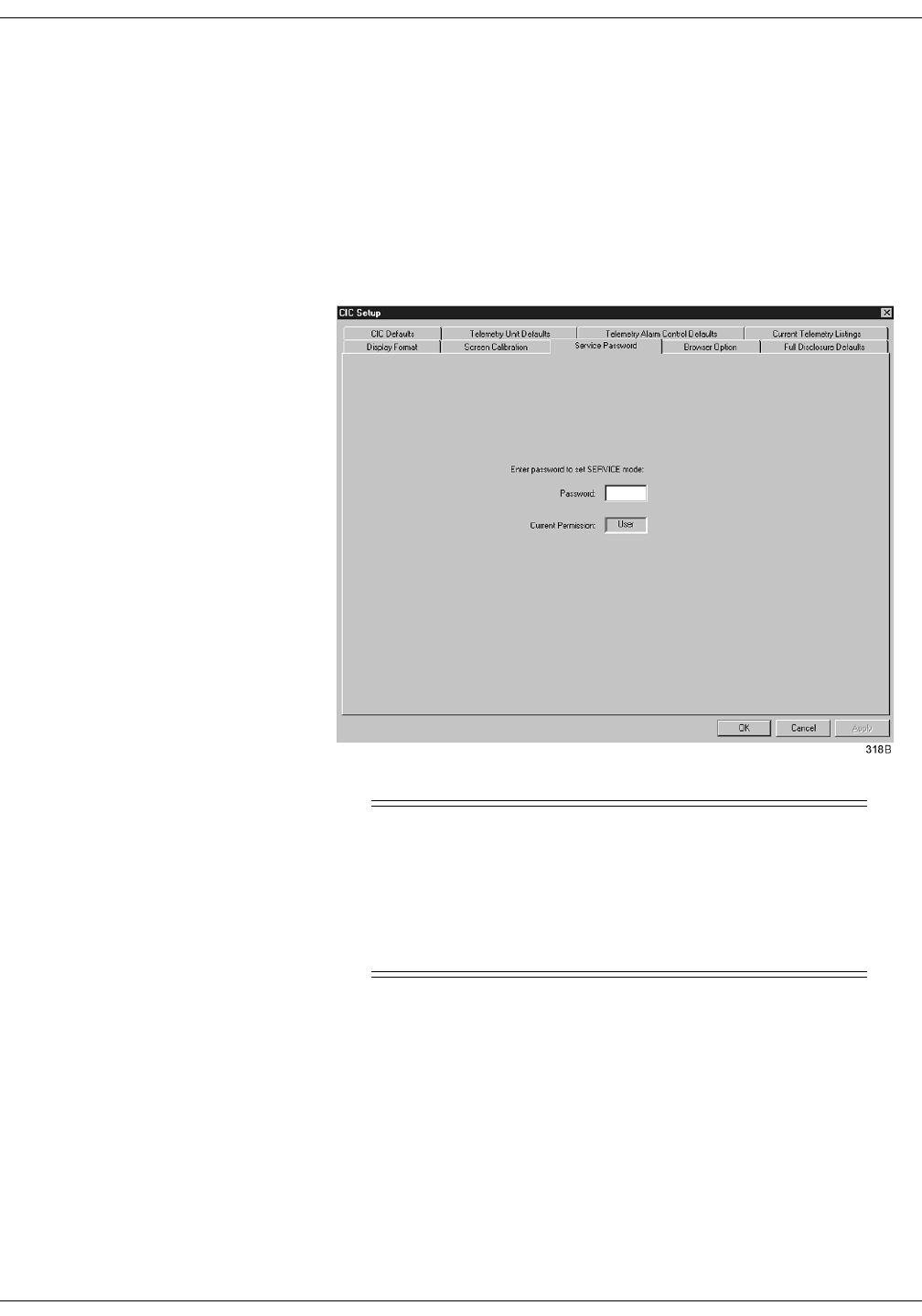
Revision A ApexPro Telemetry System 6-5
2001989-002
Telemetry Setup: Service Password
Service Password
The Service Password tab sheet contains a field for entering the
password to access the clinical information center’s service mode.
To open the Service Password tab sheet, follow these steps.
1. Use the mouse to click on Setup CIC in the main menu.
2. Click on the Service Password tab to bring it to the front.
&$87,21
The service mode is intended for use only by qualified
personnel with training and experience in its use. The
consequences of misuse include loss of alarm
configuration, loss of patient data, corruption of the
clinical information center operating system software, or
disruption of the entire Unity network.
3. To change from the user mode to the service mode, use the keyboard
to enter the service password, then click Apply. The Current
Permission entry changes from User to Service.
127(Contact your biomedical engineering department or your GE
Marquette representative to access the service mode.
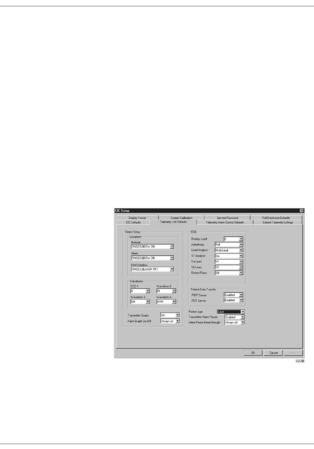
6-6 ApexPro Telemetry System Revision A
2001989-002
Telemetry Setup: Telemetry Unit Defaults
Telemetry Unit Defaults
Unit defaults are saved settings for various features and alarm levels
that apply to telemetry monitoring at the clinical information center.
Unit defaults can be set only in service mode, and once they are set, they
remain in effect and are automatically applied each time a new telemetry
patient is admitted to the clinical information center.
Viewing Telemetry Unit Defaults
You can view the current telemetry unit defaults settings by clicking on
the Setup CIC button, but defaults can only be modified when in the
service mode. Unless you are in the service mode, you will not be able to
see all available options, you will not be able to highlight the options, and
the current settings will appear dimmed.
To view Telemetry Unit Defaults, follow this procedure.
1. Click on the Setup CIC button at the bottom of the clinical
information center display. A set of tabs appears.
2. Click on the Telemetry Unit Defaults tab. The current settings for the
unit appear.

Revision A ApexPro Telemetry System 6-7
2001989-002
Telemetry Setup: Telemetry Unit Defaults
Telemetry unit defaults can be set for the following features:
Manual, alarm, and print window graph locations
ECG 1, and Waveforms 2, 3, and 4
Transmitter graph
Alarm graph on/off
Display lead
Arrhythmia
Lead analysis
ST analysis
Va and Vb leads
Detect pace
Patient data transfer PIRP server and PDT server
Patient age
Transmitter alarm pause
Alarm pause breakthrough
Once you have entered the service mode, you may modify the telemetry
unit defaults, as described below. Refer to the Service Password section
in this chapter for information about entering the service mode.
Graph Setup Graph location defaults can be set for a Manual graph location, an Alarm
graph location, and a Print Window graph location. Refer to Chapter 9,
Printing, for more information about graphing.
Waveforms
The ECG 1 popup list is used to set the unit default for the waveform
that will print in the first position on a graph. Lead II is the default.
The Waveform 2, 3, and 4 options are used to set the unit defaults for the
waveforms that will be printed in the second, third, and fourth positions
on the graph.
The options found in these popup lists are:
I
II
III
V (This option will indicate the V lead being monitored, e.g., V2.)
AVR
AVL
AVF
Off (available for Waveform 2, 3, and 4 only)

6-8 ApexPro Telemetry System Revision A
2001989-002
Telemetry Setup: Telemetry Unit Defaults
Transmitter Graph The Transmitter Graph option can be set to On or Off. When this option
is set to On, a telemetry patient can initiate a graph by pressing the
Graph button on the telemetry transmitter. When this option is set to
Off, graphs cannot be initiated at the transmitter.
This option sets the unit default for all telemetry patients admitted to
the CIC. When the Transmitter Graph option is set to On, transmitter
graph privileges can also be set on an individual patient basis using the
Enable Transmitter Graph check box in the patient’s Graph Setup tab
sheet.
Alarm Graph
The Alarm Graph On/Off option allows you to select whether a graph
will be printed when an alarm occurs. The choices are:
Always off
Always on (factory default selection)
This option sets the unit default for all patients admitted to the CIC. It
cannot be changed on an individual patient basis.
Display Lead
The options found in the popup list for the Display Lead field are:
I
II (factory default selection)
III
V (This option will indicate the V lead being monitored, e.g., V2.)
AVR
AVL
AVF
Arrhythmia
The options found in the popup list for the Arrhythmia field are:
Off
Lethal
Full (factory default selection)
Lead Analysis
The options found in the popup list for the Lead Analysis field are:
Multi-Lead (factory default selection)
Single Lead

Revision A ApexPro Telemetry System 6-9
2001989-002
Telemetry Setup: Telemetry Unit Defaults
ST Analysis
The options found in the popup list for the ST Analysis field are:
Off (factory default selection)
On
Va and Vb Lead
Use the Va Lead and Vb Lead options to set the defaults for the V leads
that will be monitored in these positions. A 6-lead cable is required for
dual V-lead monitoring. The options are:
V1
V2
V3
V4
V5
V6
Detect Pace
127(Refer to Chapter 11, ECG Monitoring, for important information
regarding Detect Pace and the pacemaker detection programs.
The options found in the popup list for the Detect Pace field are:
Off (factory default selection)
Pace 2
Pace 1
Patient Data Transfer
The PIRP Server (patient identification registration protocol server) and
PDT Server (patient data transfer server) options allow you to set the
default for patient data transfer information. Choices are:
Enabled
Disabled (factory default selection for both)
127(Changing these settings from Disabled to Enabled while patients
are admitted and full disclosure is enabled causes a loss of full
disclosure data. Full disclosure data collection stops, then starts
again immediately. However, previously stored full disclosure
data is not available.
This loss of data can be avoided by enabling the patient data
transfer options and the full disclosure option before patients are
admitted.

6-10 ApexPro Telemetry System Revision A
2001989-002
Telemetry Setup: Telemetry Unit Defaults
Patient Age
The options found in the pull-down list for the Patient Age field are:
0-2 years
3-10 years
11-13 years
Adult (factory default selection)
The patient age setting chosen in the Telemetry Unit Defaults tab sheet
affects the alarm settings. Refer to the example below.
127(This is an example of Brady changes associated with age
changes.
The Telemetry Unit Defaults tab sheet settings take precedence
when the patient age chosen in the Admit tab sheet and the age
default setting from the Telemetry Unit Defaults tab sheet
match.
When the ages do not match, the Admit tab sheet age setting
takes precedence.
Example 1. Patient Age
Telemetry Unit Defaults
Tab Sheet Setting Age Chosen In The Admit Tab
Sheet When Patient Admitted Resulting Limits Unit Default
Alarm Level (Brady) Resulting
Alarm Level
Adult Adult
0-2 years
3-10 years
11-13 years
10, 155*
90, 200
60, 180
50, 150
Message
Message
Message
Message
Message
Crisis
Crisis
Advisory
0-2 years Adult
0-2 years
3-10 years
11-13 years
50, 150
10, 155*
60, 180
50, 150
Message
Message
Message
Message
Advisory
Message
Crisis
Advisory
3-10 years Adult
0-2 years
3-10 years
11-13 years
50, 150
90, 200
10, 155*
50, 150
Message
Message
Message
Message
Advisory
Crisis
Message
Advisory
11-13 years Adult
0-2 years
3-10 years
11-13 years
50, 150
90, 200
60, 180
10, 155*
Message
Message
Message
Message
Advisory
Crisis
Crisis
Message
*These reflect the unit default values set for this example. These values will reflect whatever your unit default is set to.

Revision A ApexPro Telemetry System 6-11
2001989-002
Telemetry Setup: Telemetry Unit Defaults
Transmitter Alarm Pause
127(Refer to Chapter 8, Alarm Control, for important information
about Transmitter Alarm Pause.
The options found in the popup list for the Transmitter Alarm Pause field
are:Disabled (factory default selection)
Enabled
Always Off
This option sets the unit default for all telemetry patients admitted to
the CIC. When the Transmitter Alarm Pause option is set to Disabled or
Enabled, transmitter alarm pause privileges can also be set on an
individual patient basis using the Enable Transmitter Pause check box in
the patient’s Alarm Control tab sheet.
Alarm Pause Breakthrough
127(Refer to Chapter 8, Alarm Control, for important information
about Alarm Pause Breakthrough.
The Alarm Pause Breakthrough option allows you to set the default for
when a crisis alarm will sound, even if an alarm pause has been set. The
choices are:
Always On
Always Off (factory default selection)
This option sets the unit default for all telemetry patients admitted to
the CIC. It cannot be changed on an individual patient basis.
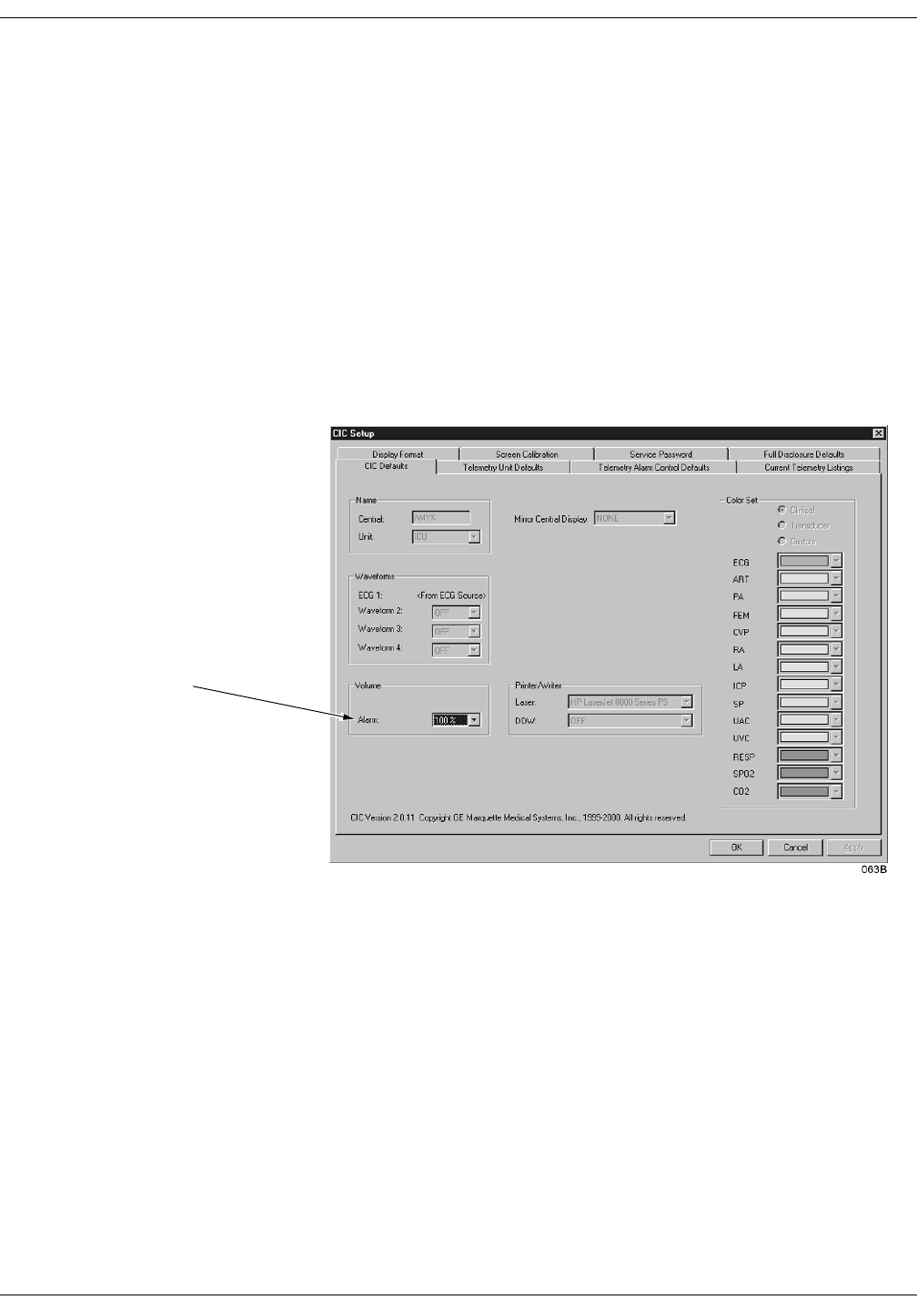
6-12 ApexPro Telemetry System Revision A
2001989-002
Telemetry Setup: CIC Defaults
CIC Defaults
You can view the current CIC default settings by clicking on the CIC
Setup button, but defaults can only be modified when in the service
mode. Unless you are in the service mode, you will not be able to see all
available options, you will not be able to highlight the options, and the
current settings will appear dimmed. Refer to the Service Password
section in this chapter.
To open the CIC Defaults tab sheet, follow these steps.
1. Click on the Setup CIC button at the bottom of the CIC display. A set
of tabs appears.
2. Click on the CIC Defaults tab to bring it to the front.
In user mode,
this is the only
active control.

Revision A ApexPro Telemetry System 6-13
2001989-002
Telemetry Setup: CIC Defaults
The following features of the CIC Defaults tab sheet can be modified in
the service mode.
Name:
Central—allows you to enter the name for this clinical
information center.
Unit—allows you to enter the care unit name for use on the Unity
network.
Waveforms:
ECG 1—this is defined by the ECG source.
Waveform 2 – 4—allows you to define multiple patient viewer
waveforms.
Volume:
Alarm—allows you to set a default alarm volume.
Printer/Writer:
Laser—allows you to designate the default laser printer for this
clinical information center.
DDW—allows you to designate the default writer for this clinical
information center.
Color Set:
Clinical—selects a preset clinical color scheme for waveforms.
Transducer—selects a preset transducer color scheme for
waveforms.
Custom—allows you to set each waveform color individually.
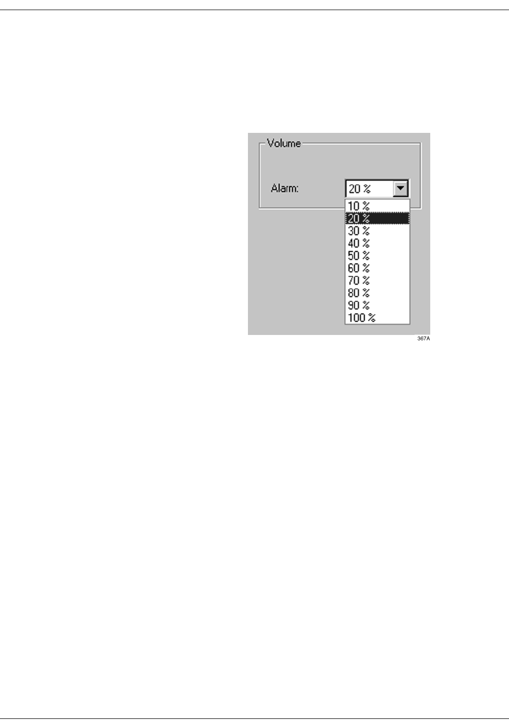
6-14 ApexPro Telemetry System Revision A
2001989-002
Telemetry Setup: CIC Defaults
Adjusting Alarm Volume
The default alarm volume can be adjusted without entering the service
mode. Follow these steps.
1. Click on the Alarm field in the Volume control area. The Alarm
Volume popup menu opens.
2. Click on the desired volume level. The volume can be set between
10% and 100%.
127(Alarm volume settings below 40% are password protected.
You must enter the service password to set the volume below
40%.
3. When you are satisfied with the new volume level, use the mouse to
click Apply to activate your change.
4. Click on another tab to bring the corresponding tab sheet to the
front, or click on the OK button in the bottom right corner of the tab
sheet to close the close the CIC Setup window and return to the
multiple patient viewer.
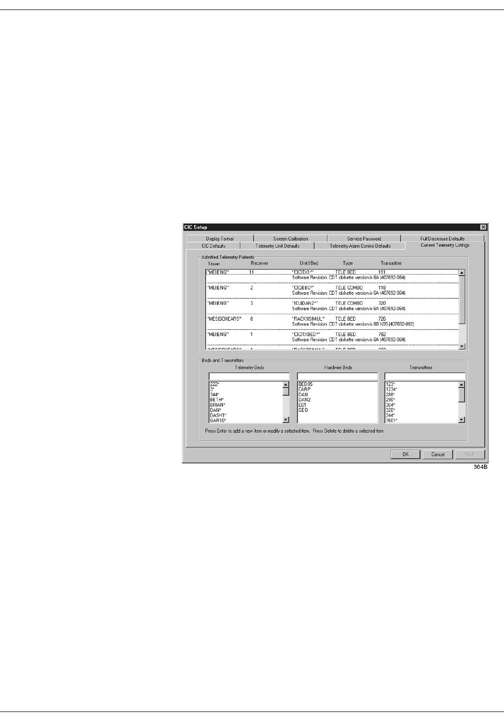
Revision A ApexPro Telemetry System 6-15
2001989-002
Telemetry Setup: Current Telemetry Listings
Current Telemetry Listings
You can view the Current Telemetry Listings by clicking on the Setup
CIC button, but defaults can only be modified when in the service mode.
Refer to the Service Password section in this chapter.
The Current Telemetry Listings tab sheet allows you to view
characteristics of telemetry settings. To open the Current Telemetry
Listings tab sheet, follow these steps.
1. Click on the Setup CIC button at the bottom of the display. A set of
tabs appears.
2. Click on the Current Telemetry Listings tab to bring it to the front.
The Admitted Telemetry Patients control is for information only. The
Beds and Transmitters controls can only be modified from within the
service mode.

6-16 ApexPro Telemetry System Revision A
2001989-002
Telemetry Setup: Current Telemetry Listings
Admitted Telemetry Patients
127(This overview covers the controls in a row. Each row contains
information for one telemetry patient.
The second line of an entry shows the current software level for
the patient bed in question.
Tower—indicates which telemetry receiver system this telemetry
patient is communicating with.
Receiver—indicates the receiver inside the telemetry receiver system
with which this telemetry transmitter is communicating.
Unit|Bed—indicates the unit and bed to which this patient has been
assigned.
Type—indicates the type of patient this is: Tele Bed or Tele Combo.
Transmitter—indicates the identification number assigned to this
patient’s transmitter.
Bed and Transmitters Telemetry Beds—allows you to add, modify, or delete a telemetry bed
name.
Hardwire Beds—allows you to add, modify, or delete a hardwire bed
name.
Transmitters—allows you to add, modify, or delete a telemetry
transmitter.
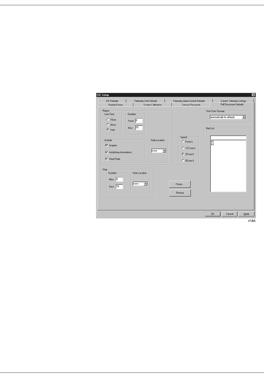
Revision A ApexPro Telemetry System 6-17
2001989-002
Telemetry Setup: Full Disclosure Defaults
Full Disclosure Defaults
The Full Disclosure Defaults tab sheet is used to set up the defaults for
full disclosure monitoring. You must enter the service mode to make any
modifications to this tab sheet. Refer to the Service Password section in
this chapter for more information about entering the service mode.
Below is an illustration of the Full Disclosure Defaults tab sheet. For
complete details about the full disclosure function, please refer to the
Clinical Information Center Operator’s Manual.

6-18 ApexPro Telemetry System Revision A
2001989-002
Telemetry Setup: Full Disclosure Defaults
For your notes

Revision A ApexPro Telemetry System 7-1
2001989-002
7Admit/View a Patient
About Admitting . . . . . . . . . . . . . . . . . . . . . . . . . . . . . . . . . . . . . . . . . . . . . . . . . . . . . 7-3
Switching Transmitters . . . . . . . . . . . . . . . . . . . . . . . . . . . . . . . . . . . . . . . . . . . . . .7-3
Terminology . . . . . . . . . . . . . . . . . . . . . . . . . . . . . . . . . . . . . . . . . . . . . . . . . . . . . .7-3
Telemetry Monitoring . . . . . . . . . . . . . . . . . . . . . . . . . . . . . . . . . . . . . . . . . . .7-3
Bedside Monitoring . . . . . . . . . . . . . . . . . . . . . . . . . . . . . . . . . . . . . . . . . . . .7-3
Locked and Unlocked Beds . . . . . . . . . . . . . . . . . . . . . . . . . . . . . . . . . . . . . .7-3
Admit Instructions . . . . . . . . . . . . . . . . . . . . . . . . . . . . . . . . . . . . . . . . . . . . . . . . . . . 7-4
Admit Procedure . . . . . . . . . . . . . . . . . . . . . . . . . . . . . . . . . . . . . . . . . . . . . . . . . .7-4
Discharge Instructions . . . . . . . . . . . . . . . . . . . . . . . . . . . . . . . . . . . . . . . . . . . . . . . 7-7
Clearing a Patient Window . . . . . . . . . . . . . . . . . . . . . . . . . . . . . . . . . . . . . . . . . . 7-8
Viewing a Patient . . . . . . . . . . . . . . . . . . . . . . . . . . . . . . . . . . . . . . . . . . . . . . . . . . . . 7-9
Sample . . . . . . . . . . . . . . . . . . . . . . . . . . . . . . . . . . . . . . . . . . . . . . . . . . . . . . . . . .7-9
Relearn . . . . . . . . . . . . . . . . . . . . . . . . . . . . . . . . . . . . . . . . . . . . . . . . . . . . . . . . .7-9
Viewing Another Patient . . . . . . . . . . . . . . . . . . . . . . . . . . . . . . . . . . . . . . . . . . . . . 7-10
Viewing in the Single Patient Viewer . . . . . . . . . . . . . . . . . . . . . . . . . . . . . . . . . .7-10
Viewing in the Multiple Patient Viewer . . . . . . . . . . . . . . . . . . . . . . . . . . . . . . . . 7-11
Alarm Condition Indicators . . . . . . . . . . . . . . . . . . . . . . . . . . . . . . . . . . . . . . . . . . . 7-13


Revision A ApexPro Telemetry System 7-3
2001989-002
Admit/View a Patient: About Admitting
About Admitting
Switching Transmitters
If you wish to switch to an ApexPro transmitter from a CD Telemetry-
LAN transmitter (Apex S, Apex 5, Apex 3, or CD Telemetry transmitter)
or vice versa while a patient is admitted, you must follow this procedure:
Discharge the patient (losing stored data).
Switch transmitters.
Re-admit the patient.
Monitoring will stop if you switch transmitters while a patient is
admitted. Attempting to change the TTX number for an admitted
telemetry patient at the CIC will generate the message “INVALID TTX.”
Terminology
For the purposes of this document, the following terms apply:
Telemetry Monitoring Telemetry monitoring occurs when patient vital signs data is
transmitted by a telemetry transmitter to a telemetry receiver system
over an established antenna system and viewed at a clinical information
center. The clinical information center identifies a telemetry bed by
placing an asterisk next to the bed name (e.g., IMC|BED4*). ECG data
is processed by the telemetry receiver system.
Bedside Monitoring A bedside monitor is a stationary monitor (user-configured or factory-
configured). These monitors are connected directly to the patient via an
ECG cable. They are set up with a unit name as well as a bed name (e.g.,
IMC|BED4). For a user-configured monitor, ECG data is processed by
an acquisition module. For a factory-configured monitor, ECG data is
processed within the monitor itself.
For information about bedside monitoring at the clinical information
center, refer to the Clinical Information Center Operator’s Manual.
Locked and Unlocked Beds
The clinical information center can be configured with the bed names in
either locked or unlocked mode. When locked, the bed names are
permanently assigned to specific windows.
For information about locked and unlocked beds, refer to the service
manual for the clinical information center.
127(It is possible to admit a patient to a window with a bed name
that is locked to NONE. To avoid duplication of patient
waveforms, a window locked to NONE should not be used to
admit a patient.
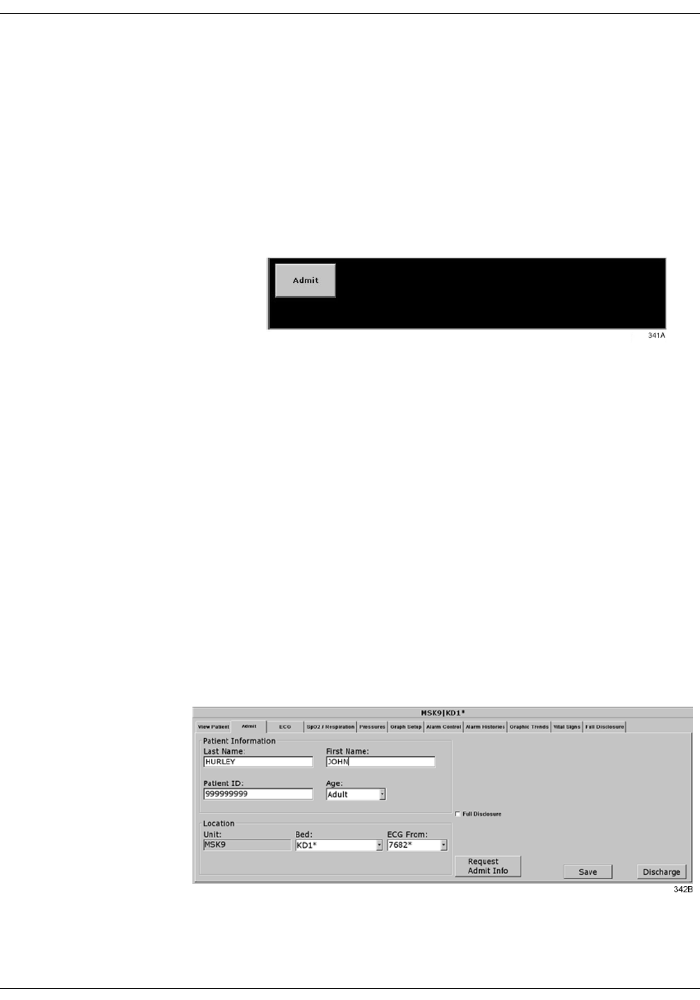
7-4 ApexPro Telemetry System Revision A
2001989-002
Admit/View a Patient: Admit Instructions
Admit Instructions
Admitting a telemetry patient is a simple, yet important procedure. After
you have prepared the patient’s skin, properly placed the electrodes, and
set up the transmitter(s), the patient can be admitted.
Admit Procedure
1. At the clinical information center, choose a bed window that is blank
except for an Admit button.
If a bed window similar to the one illustrated above does not appear
on your clinical information center, click on the Auto Display button
in the main menu at the bottom of the display. The display will
rearrange to add at least one empty bed window with an Admit
button.
127(If there are no additional bed windows available, the
message “Reconfiguration failed!” will appear. Do a discharge
to make a bed window available for admit. For more
information on discharging, refer to the Discharging a
Patient section in this chapter.
127(A bed window that still contains some patient information
and the message “DISCHARGED” is available for admit. For
information on clearing the data and making this type of
window available for admit, refer to the Clearing a Patient
Window section in this chapter.
2. Use the mouse to click on the Admit button. The single patient
viewer appears at the bottom of the display, with the Admit tab in
front.
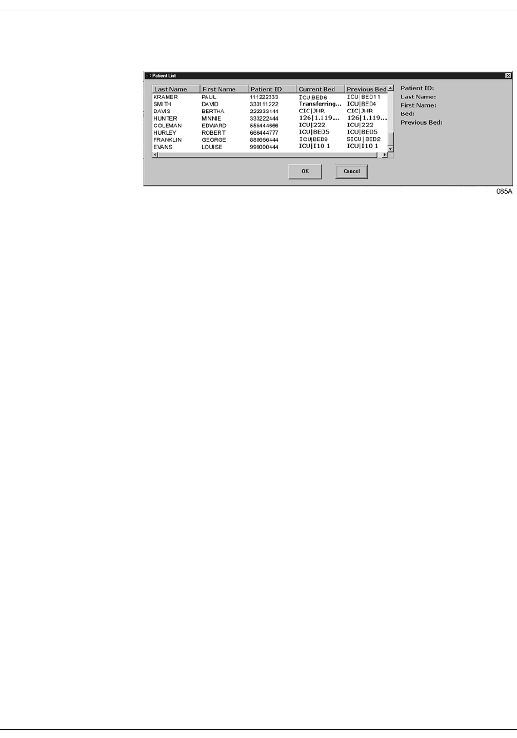
Revision A ApexPro Telemetry System 7-5
2001989-002
Admit/View a Patient: Admit Instructions
3. Click on the Request Admit Info button. If any patient information is
available from the PDT server, the Patient List window opens.
a. If the patient information you want is listed in the Patient List
window, click on it.
b. Click OK to select your choice, or click Cancel to close the window
without making a selection.
If no information is available from the PDT server, or if the PDT
server itself is not available, the clinical information center will
query the hospital information system. If HL7 admit data is
available on a MUSE system or a QS system, the appropriate fields
on the Admit tab sheet are populated with data from those devices.
If patient information is not available from either the PDT server or
the hospital information system, an error message appears.
Information for the fields on the Admit tab sheet must be entered
manually. Proceed to step 4 to do this.
Proceed to step 7 if you do not need to enter or change any of the
patient information.
4. Select the desired bed number by using the mouse to click on the
down arrow that appears to the right of the Bed field. A popup list of
beds in the unit appears. Click on your choice to select it.
The bed number selection will not change if the bed number is
locked. (Refer to the service manual for the clinical information
center for more information about locked beds.)
5. Select the source of the ECG in the ECG From field. Click on the
down arrow at the right of the field, and a popup list of choices will
appear. Click on your choice to select it.
Be sure that the TTX number you select from this list matches the
TTX number on the back of the ApexPro transmitter connected to the
patient.
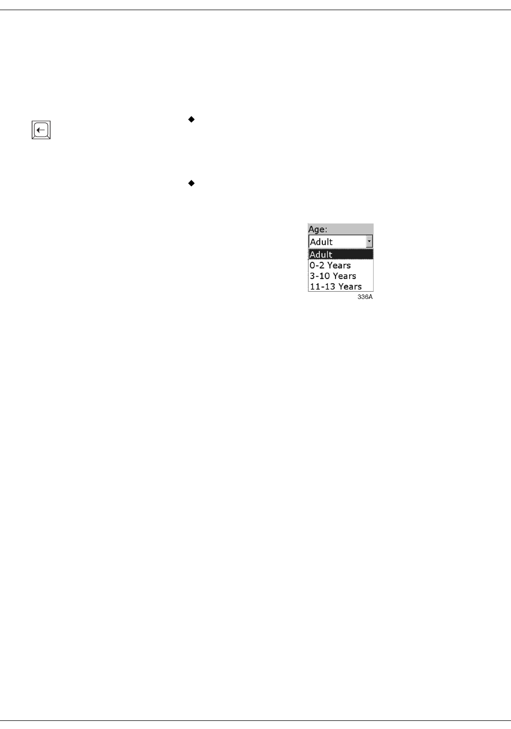
7-6 ApexPro Telemetry System Revision A
2001989-002
Admit/View a Patient: Admit Instructions
6. You can enter patient information by clicking in the various patient
information fields, typing in the information, and then tabbing into
or clicking in the next field. The patient information that should be
entered is: Last Name, First Name, Patient ID, and Age. You do not
have to enter this information in order to admit a patient. However,
it is recommended that you enter it.
Last Name, First Name, and Patient ID are entered using the
keyboard. Click or tab into the field before typing the
information. Press the backspace key (shown at left) to delete
characters when changing or correcting the patient’s name or ID
number.
Age appears as a popup list of selections. Click on the down arrow
to the right of the field to open the list. Click on your choice to
select it.
7. Once you have entered all the patient information desired, click on
the Admit button in the lower right corner of the tab sheet to admit
the patient.
343A
Backspace Key
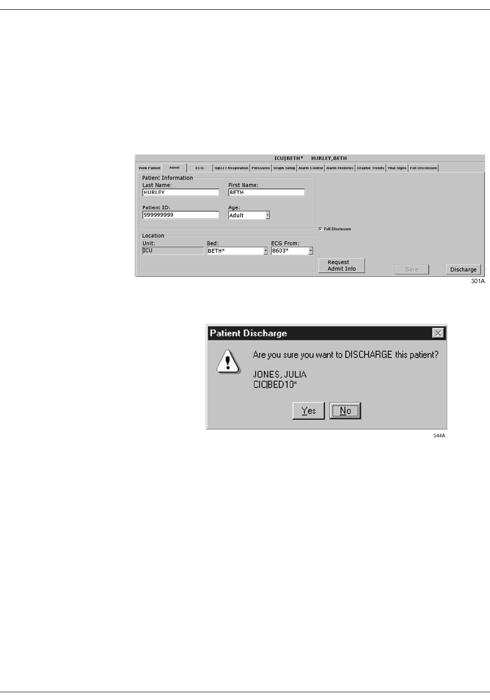
Revision A ApexPro Telemetry System 7-7
2001989-002
Admit/View a Patient: Discharge Instructions
Discharge Instructions
To discharge a patient, follow this procedure:
1. At the clinical information center, click on the bed window of the
patient you wish to discharge. The display rearranges to
accommodate the single patient viewer at the bottom of the display.
2. Click on the Admit tab to bring the tab sheet to the front.
3. Click on the Discharge button in the lower right corner of the tab
sheet. A dialog box similar to the one below appears on the display.
4. Click on the Yes button or type the letter Y on the keyboard if this is
the patient you wish to discharge. All patient information will clear.
While the information is being cleared, the message “Discharging
patient…” appears briefly on the Admit tab sheet.
The single patient viewer closes, and the display returns to the multiple
patient viewer. The bed window of the patient you just discharged will
show the message “DISCHARGED” at the bottom of the window. If the
bed is not locked, the “DISCHARGED” message disappears and an
Admit button appears in the window as soon as the display is rearranged
or refreshed. If the bed is locked, the “DISCHARGED” message remains
on the bed window.
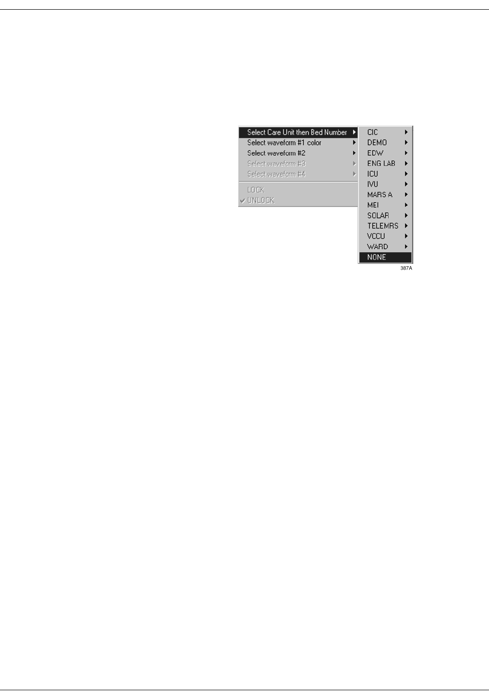
7-8 ApexPro Telemetry System Revision A
2001989-002
Admit/View a Patient: Discharge Instructions
Clearing a Patient Window
To clear discharged patient information from the window and bring up
the Admit button, use the right-click menu.
1. Use the right mouse button to click anywhere inside a discharged
bed window. The right-click menu appears.
2. Slide the mouse over the Select Care Unit, then Bed Number text,
without pressing either mouse button. The text highlights, and a list
of units on the network pops up.
3. Without pressing either mouse button, slide the mouse pointer to
None at the bottom of the list. Click the left mouse button on None.
4. The popup list closes, and the patient window will now be empty,
except for an Admit button.
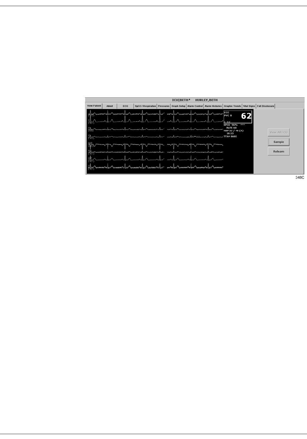
Revision A ApexPro Telemetry System 7-9
2001989-002
Admit/View a Patient: Viewing a Patient
Viewing a Patient
When you wish to see detailed information about a patient’s status, you
can use the View Patient tab in the single patient viewer.
1. Click in the bed window of the patient you wish to view. The display
rearranges to accommodate the single patient viewer at the bottom.
2. Click on the View Patient tab to bring it to the front.
The View Patient tab sheet shows all the information that normally
appears in patient’s bed window in the multiple patient viewer, and also
displays up to eight leads of ECG waveforms.
There are two buttons in the View Patient tab sheet that can be used for
telemetry patients. Their functions are described below.
127(The third button, View All ECG, is dimmed when viewing
telemetry patients because all the ECG waveforms available for
telemetry patients are normally displayed.
Sample
Clicking on the Sample button records a sample of the patient’s real-time
ECG data. This sample is then stored in alarm histories, and can be
viewed in the Alarm Histories tab sheet under the title of Sample. For
more information about viewing alarm histories, refer to Chapter 10,
Patient Data, in this manual.
Relearn
Clicking on the Relearn button initiates a relearn of the patient’s ECG
rhythm. The relearn takes only a few seconds. The patient’s heart rate
reading will appear as Xs momentarily, and then be replaced by
numerics once the relearn is complete.
Use the relearn function whenever there has been a significant change in
the patient’s rhythm.
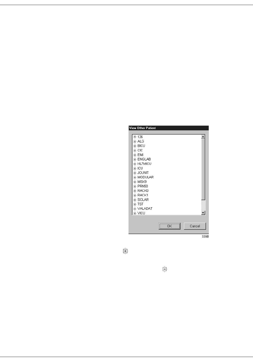
7-10 ApexPro Telemetry System Revision A
2001989-002
Admit/View a Patient: Viewing Another Patient
Viewing Another Patient
127(When viewing a patient from another unit, you cannot make any
changes to the patient’s information or settings.
Viewing in the Single Patient Viewer
To display the single patient viewer of a patient on the network who is
not currently displayed on your clinical information center, follow the
steps below.
1. Click on the View Other button in the Main Menu at the bottom of
the clinical information center display.
2. The View Other Patient window appears. This window displays all
the units currently available on your network.
3. Click on the next to the unit from which you wish to view a bed. A
list of beds admitted to that unit appears below the unit name.
127(If a unit name has a next to it but no bed list below it,
there are no beds admitted into that unit.
4. Click on the bed name you wish to view. The name is highlighted.
5. Click on the OK button. The single patient viewer opens at the
bottom of the display, showing the viewed patient’s data.
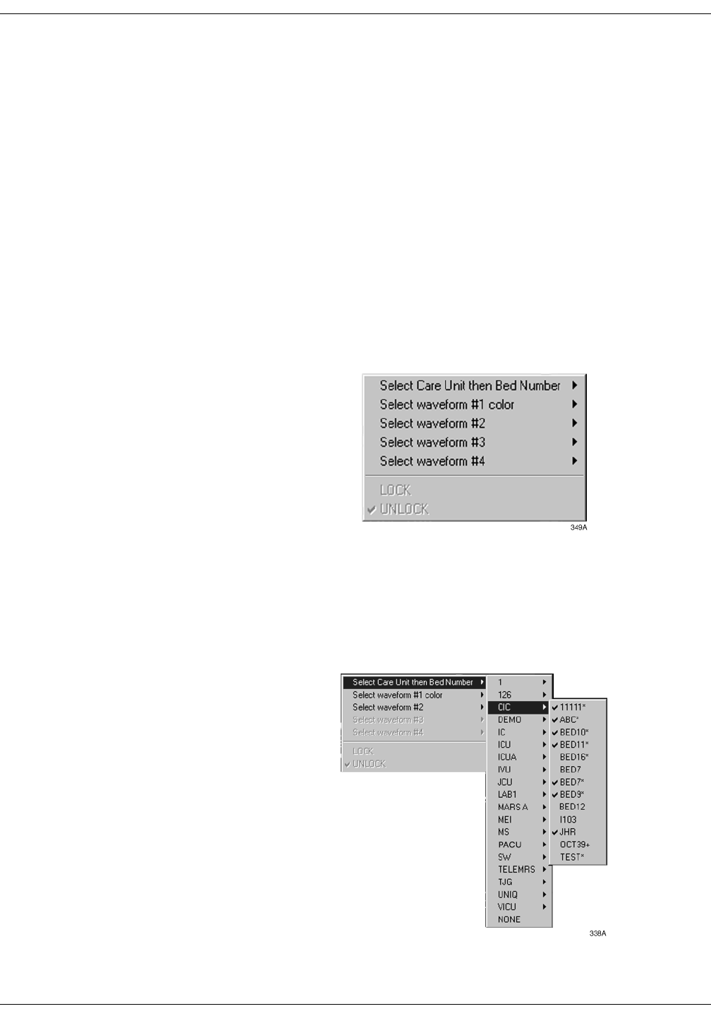
Revision A ApexPro Telemetry System 7-11
2001989-002
Admit/View a Patient: Viewing Another Patient
Viewing in the Multiple Patient Viewer
When in the multiple patient viewer, you can replace the data in any bed
window with the data from another patient on the network who is not
currently displayed on your clinical information center.
127(The data for the patient who was originally displayed in the bed
window you select will not be visible on your clinical information
center once you use that patient’s bed window to view another
patient.
To view another patient in the multiple patient viewer, follow the steps
below.
1. Use the right mouse button to click anywhere inside a bed window.
The right-click menu appears.
127(You must use the right mouse button to access the right-click
menu.
2. Slide the mouse over the Select Care Unit then Bed Number text,
without pressing either mouse button. The text highlights, and a list
of units on the network pops up.
3. Without pressing either mouse button, slide the mouse pointer to the
unit name you wish to select a bed from. The unit name highlights,
and a list of beds on that unit pops up.

7-12 ApexPro Telemetry System Revision A
2001989-002
Admit/View a Patient: Viewing Another Patient
4. Without pressing either mouse button, slide the mouse pointer to the
bed you wish to view. The bed name becomes highlighted.
127(A check mark next to a bed name means that the bed is
already being viewed at this clinical information center.
5. Once you have chosen the bed you wish to view, and its bed name is
highlighted on this list, use the left mouse button to click on the bed
name.
6. The popup lists close, and the viewed patient’s data appears in the
bed window.
For more detailed patient information, use the left mouse button to
click in the bed window. The single patient viewer will open at the
bottom of the display, allowing you to view all the patient’s data.

Revision A ApexPro Telemetry System 7-13
2001989-002
Admit/View a Patient: Alarm Condition Indicators
Alarm Condition Indicators
You can open the single patient viewer for any patient in your care unit
who is experiencing an alarm condition.
When a patient experiences an alarm condition, a red button appears at
the bottom of the clinical information center display. The button contains
the unit name and bed number, as well as the cause of alarm.
To access the single patient viewer for the alarming patient, simply click
on the red button at the bottom of the display. The display rearranges to
accommodate the single patient viewer at the bottom of the display, and
all the patient’s information will be available to you.

7-14 ApexPro Telemetry System Revision A
2001989-002
Admit/View a Patient: Alarm Condition Indicators
For your notes

Revision A ApexPro Telemetry System 8-1
2001989-002
8Alarm Control
Alarm Structure . . . . . . . . . . . . . . . . . . . . . . . . . . . . . . . . . . . . . . . . . . . . . . . . . . . . . 8-3
Patient Status Alarms . . . . . . . . . . . . . . . . . . . . . . . . . . . . . . . . . . . . . . . . . . . . . .8-3
Colored Window Borders . . . . . . . . . . . . . . . . . . . . . . . . . . . . . . . . . . . . . . . .8-4
Automatic Alarm Graphs . . . . . . . . . . . . . . . . . . . . . . . . . . . . . . . . . . . . . . . .8-4
System Status Alarms . . . . . . . . . . . . . . . . . . . . . . . . . . . . . . . . . . . . . . . . . . . . . .8-4
Alarm Control Tab . . . . . . . . . . . . . . . . . . . . . . . . . . . . . . . . . . . . . . . . . . . . . . . . . . . 8-5
Accessing the Alarm Control Tab . . . . . . . . . . . . . . . . . . . . . . . . . . . . . . . . . . . . .8-5
Parameter Limits . . . . . . . . . . . . . . . . . . . . . . . . . . . . . . . . . . . . . . . . . . . . . . . . . 8-6
Parameter Alarm Levels . . . . . . . . . . . . . . . . . . . . . . . . . . . . . . . . . . . . . . . . . . . .8-6
Arrhythmia Alarm Levels . . . . . . . . . . . . . . . . . . . . . . . . . . . . . . . . . . . . . . . . . . . 8-7
Alarms On/Off . . . . . . . . . . . . . . . . . . . . . . . . . . . . . . . . . . . . . . . . . . . . . . . . . . . 8-8
Alarm Off Reason . . . . . . . . . . . . . . . . . . . . . . . . . . . . . . . . . . . . . . . . . . . . .8-9
Enable Transmitter Pause . . . . . . . . . . . . . . . . . . . . . . . . . . . . . . . . . . . . . .8-10
Alarm Pause Breakthrough Enabled/Disabled . . . . . . . . . . . . . . . . . . . . . . .8-10
Recalling Unit Defaults . . . . . . . . . . . . . . . . . . . . . . . . . . . . . . . . . . . . . . . . . . . . .8-10
Alarm Help . . . . . . . . . . . . . . . . . . . . . . . . . . . . . . . . . . . . . . . . . . . . . . . . . . . . . 8-11
Printing Alarm Settings . . . . . . . . . . . . . . . . . . . . . . . . . . . . . . . . . . . . . . . . . . . .8-11
Alarm Pause Breakthrough . . . . . . . . . . . . . . . . . . . . . . . . . . . . . . . . . . . . . . . . . . 8-12
Factory Alarm Default Settings . . . . . . . . . . . . . . . . . . . . . . . . . . . . . . . . . . . . . . . 8-14
Patient Status Alarms . . . . . . . . . . . . . . . . . . . . . . . . . . . . . . . . . . . . . . . . . . . . .8-14
Crisis Alarms . . . . . . . . . . . . . . . . . . . . . . . . . . . . . . . . . . . . . . . . . . . . . . . .8-14
Warning Alarms . . . . . . . . . . . . . . . . . . . . . . . . . . . . . . . . . . . . . . . . . . . . . .8-14
System Status Alarms . . . . . . . . . . . . . . . . . . . . . . . . . . . . . . . . . . . . . . . . . . . . 8-15
System Warning Alarms . . . . . . . . . . . . . . . . . . . . . . . . . . . . . . . . . . . . . . .8-15
System Advisory Alarms . . . . . . . . . . . . . . . . . . . . . . . . . . . . . . . . . . . . . . .8-15
Unit Default Settings for Alarms . . . . . . . . . . . . . . . . . . . . . . . . . . . . . . . . . . . . . . 8-16
Telemetry Alarm Control Defaults . . . . . . . . . . . . . . . . . . . . . . . . . . . . . . . . . . . .8-16
Parameter Limits . . . . . . . . . . . . . . . . . . . . . . . . . . . . . . . . . . . . . . . . . . . . .8-17
Parameter Alarm Levels . . . . . . . . . . . . . . . . . . . . . . . . . . . . . . . . . . . . . . .8-18
Arrhythmia Alarm Levels . . . . . . . . . . . . . . . . . . . . . . . . . . . . . . . . . . . . . . .8-19

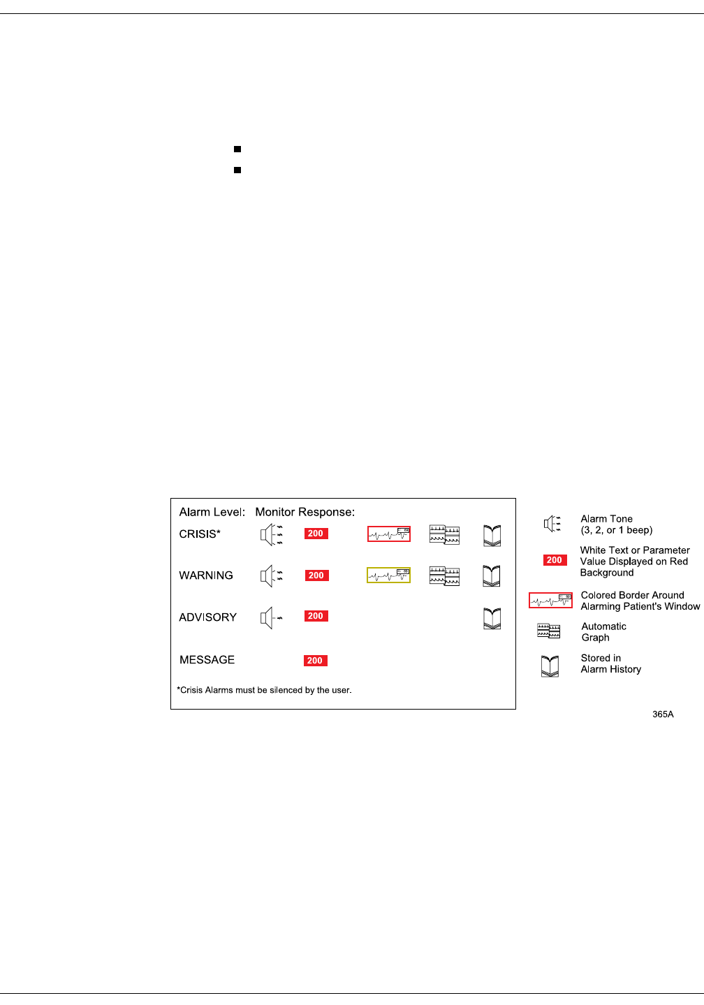
Revision A ApexPro Telemetry System 8-3
2001989-002
Alarm Control: Alarm Structure
Alarm Structure
The alarm structure of the clinical information center is divided into two
classifications:
Patient status alarms
System status alarms
Within each classification there are levels that correlate to the severity of
the condition that is causing the alarm. The levels and how the clinical
information center responds to each are described below.
Patient Status Alarms
Patient status alarms are triggered by a patient condition that exceeds
parameter limits, or by an arrhythmia condition. Patient status alarms
provide the highest priority information.
The levels within the patient status alarm category and how the clinical
information center responds to each are shown in the following chart.
The chart begins with the most critical type of alarm (Crisis) and ends
with the least critical type of alarm (Message).
127(Only arrhythmia alarm conditions are stored in alarm histories.
Patient Status Alarms Chart
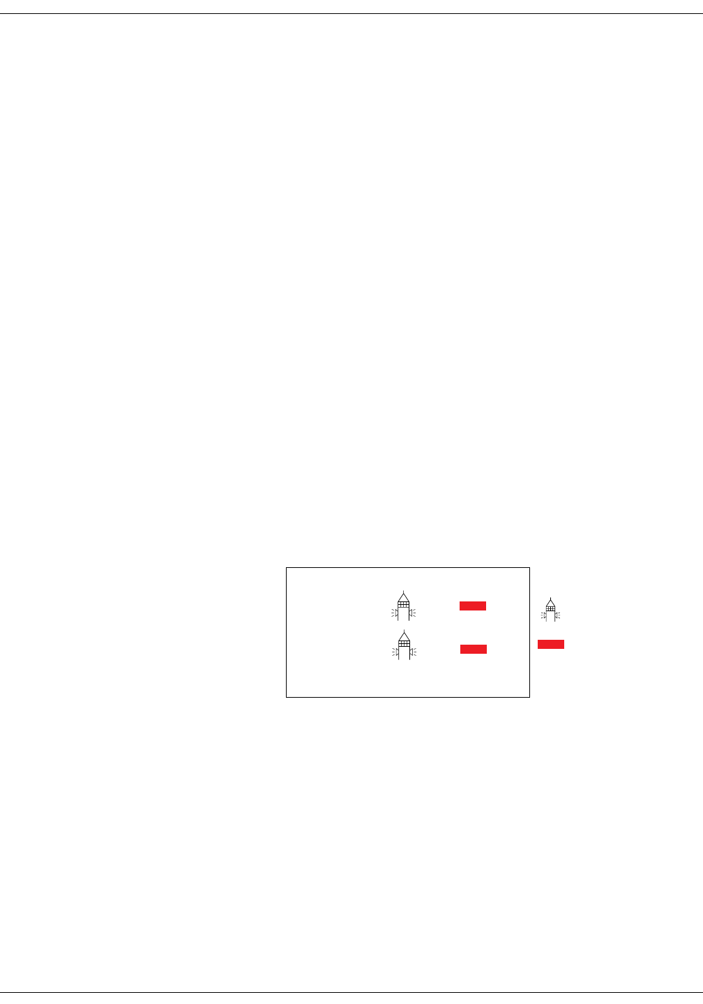
8-4 ApexPro Telemetry System Revision A
2001989-002
Alarm Control: Alarm Structure
Colored Window Borders Crisis and Warning alarms are indicated with a large border around the
individual patient’s bed window in the multiple patient viewer. This
border flashes on and off several times when the alarm occurs before
staying on. The color of the border indicates the severity of the alarm —
red for a Crisis alarm and yellow for a Warning alarm. When the alarm
is silenced, the colored border reverts to the black background.
127(Only Crisis and Warning alarms activate the colored border.
Patients selected for single patient view have a white border in
the multiple patient viewer.
Automatic Alarm Graphs A graph prints automatically when a patient experiences a Crisis or
Warning alarm. Arrhythmia alarm graphs run until the end of the alarm
event. The printer prints the 10 seconds of data that occurred
immediately before the event, and prints for the duration of the event.
The printer stops printing when the patient returns to a normal rhythm.
If a printer is not available at the time of the alarm event, a 20-second
graph is saved. This saved graph will print when a printer becomes
available.
System Status Alarms
System status alarms are triggered by mechanical or electrical problems
and are of lesser priority than patient status alarms. The levels within
the system status alarm category and how the clinical information center
responds to each are shown in the following chart.
System Status Alarms Chart
Unlike patient status alarms, system status alarms cannot be moved
from one level to another.
Fog-horn
Tone
WARNING
ADVISORY
Alarm Level: Monitor Response:
Warning sounds continuously. Advisory sounds only once. 366A
TEXT
TEXT
TEXT White Text
Displayed on
Red Background
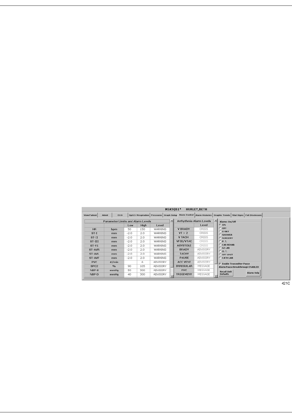
Revision A ApexPro Telemetry System 8-5
2001989-002
Alarm Control: Alarm Control Tab
Alarm Control Tab
Parameter and arrhythmia alarm levels are, from most critical to least
critical, Crisis, Warning, Advisory, and Message.
Each alarm level elicits a specific response from the clinical information
center. The four alarm levels are configurable. This means that an alarm
can be moved from one category to another if the default is not
satisfactory to your situation. This is done in the Alarm Control tab sheet
for the patient whose alarm settings you wish to adjust.
127(ASYSTOLE and VFIB/VTAC alarms cannot be moved from the
Crisis level.
For neonatal patients, BRADY, ASYSTOLE, and VFIB/VTAC
alarms cannot be moved from the Crisis level.
Accessing the Alarm Control Tab
1. Use the mouse to click in the window of the telemetry patient whose
alarm settings you wish to view or change.
2. The clinical information center display rearranges as the single
patient viewer opens at the bottom of the display. Click on the
patient’s Alarm Control tab to bring the tab sheet to the front.
The telemetry patient Alarm Control tab sheet is divided into three
sections: Parameter Limits and Alarm Levels, Arrhythmia Alarm Levels,
and Alarms On/Off. The options on this tab sheet are detailed on the
following pages.
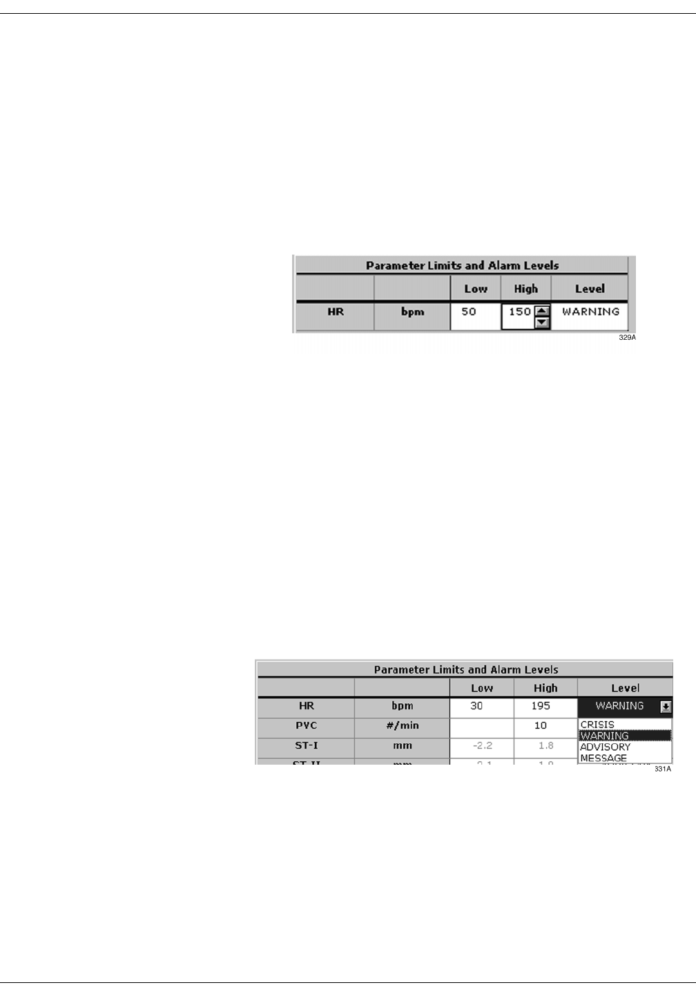
8-6 ApexPro Telemetry System Revision A
2001989-002
Alarm Control: Alarm Control Tab
Parameter Limits
1. To change the individual patient’s settings for Parameter Limits and
Alarm Levels, click in the Low or High field for the parameter you
wish to change.
127(The alarm limits for some parameters cannot be changed. To
indicate that they cannot be changed, the text in the Low and
High fields for these parameters always appears dimmed.
Once you click in the field, it is framed by a rectangle, and up and
down arrow buttons appear in the field.
127(Alarms generated by
parameter limit violations are not
stored in Alarm Histories.
2. To increase or decrease the limit by 5, click on the up or down arrow
button.
To increase or decrease the limit in increments other than 5, use the
keyboard to enter a new limit value.
3. If you are finished making changes in the Alarm Control tab sheet,
click on the Close button in the bottom right corner of the display to
close the single patient viewer.
Parameter Alarm Levels
1. Click in the Level field for the parameter whose alarm level is to be
changed. A down arrow button appears in the field.
2. Click on the down arrow button. A popup list of alarm level selections
appears.
127(Alarms are always sorted
from top to bottom in highest to
lowest priority. When you change a
level, the list is re-sorted to reflect
the change in alarm priority.
3. Click on the desired alarm level to select it.
4. If you are finished making changes in the Alarm Control tab sheet,
click on the Close button in the bottom right corner of the display to
close the single patient viewer.
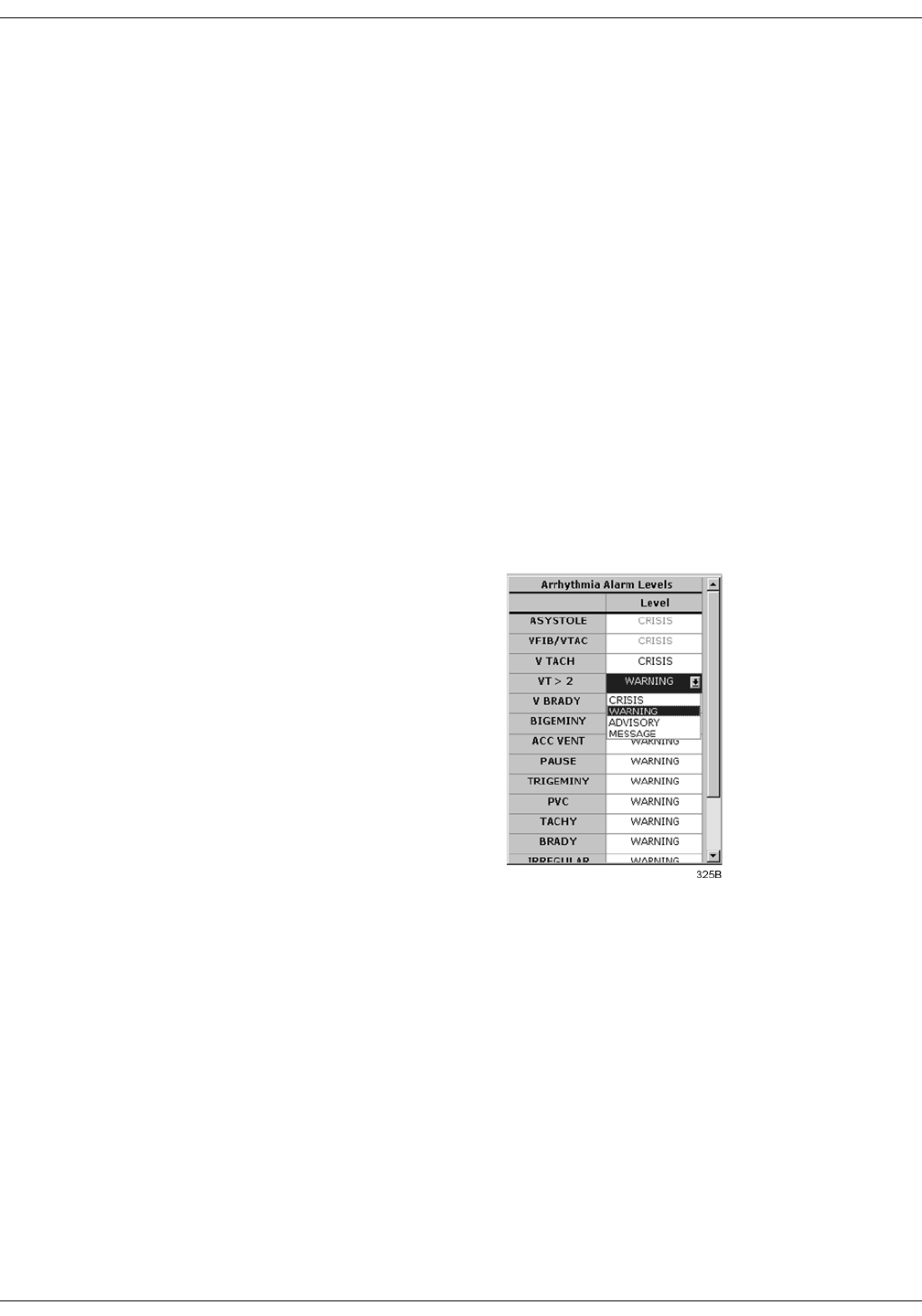
Revision A ApexPro Telemetry System 8-7
2001989-002
Alarm Control: Alarm Control Tab
Arrhythmia Alarm Levels
1. To change the Arrhythmia Alarm Levels, click in the Level field of the
arrhythmia alarm you wish to change. A down arrow button appears
in the field.
127(The Arrhythmia Alarm Levels for ASYSTOLE and VFIB/
VTAC cannot be changed. Therefore, the text in the Level
field for these alarms always appears dimmed.
For neonatal patients, the Arrhythmia Alarm Levels for
BRADY, ASYSTOLE and VFIB/VTAC cannot be changed.
Therefore, the text in the Level field for these alarms always
appears dimmed.
127(You may need to use the scroll bar on the right side of the
Arrhythmia Alarm Levels section in order to view the
arrhythmia alarm that you wish to modify.
127(Alarm levels are usually shown in black type. An alarm level
shown in blue indicates that it is not the default level.
2. Click on the down arrow button. A popup list of alarm level selections
appears.
3. Click on your choice to select it.
4. If you are finished making changes in the Alarm Control tab sheet,
click on the Close button in the bottom right corner of the display to
close the single patient viewer.
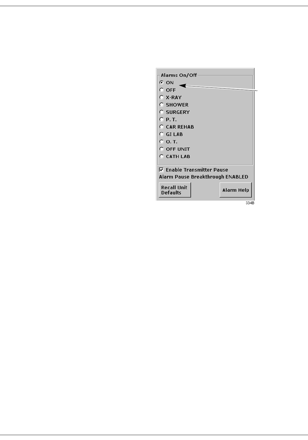
8-8 ApexPro Telemetry System Revision A
2001989-002
Alarm Control: Alarm Control Tab
Alarms On/Off
To turn a telemetry patient’s alarms on or off, click on the appropriate
radio button or on the text itself in the Alarms On/Off section of the
Alarm Control tab.
Selecting Off turns all alarms off until you turn them back on by
selecting On.
127(Refer to the Alarm Pause Breakthrough section in this chapter
for important information about turning alarms off.
ON
and
OFF
buttons

Revision A ApexPro Telemetry System 8-9
2001989-002
Alarm Control: Alarm Control Tab
Alarm Off Reason Selecting from a list of reasons, you can define why alarms have been
turned off. This text is displayed in addition to the ALARMS OFF
message in the patient’s window at the clinical information center.
The following are the options for alarms off reasons.
Selecting OFF turns all alarms off until you turn them back on.
Selecting any reason establishes an alarm pause state for 5 minutes
in the presence of a valid waveform. After 5 minutes, alarms will
reactivate if the patient is within range of the antenna system for 15
seconds or longer. If the patient remains out of antenna range, the
alarm pause state will continue until the patient re-enters antenna
range for 15 seconds or longer.
127(The patient must be in antenna range for the alarm pause
state to cease.
:$51,1*
Alarms do not sound, alarm histories are not stored, and
alarm graphs do not print during an alarms off with
reason condition.
The alarms off reason appears in the event trend for graphic trends.
If the patient is in LEADS FAIL or NO TELEM and an alarms off
reason is selected, the reason is displayed in the waveform window.
127(Refer to the Alarm Pause Breakthrough section in this chapter
for important alarm pause information.
Alarms Off Reason Text Displayed At Clinical
Information Center Text Printed On Graph
On (no text) (no text)
Off ALARMS OFF OFF
X-ray XRAY XRA
Shower SHOWER SHW
Surgery SURGERY OR
Physical therapy P.T. PT
Cardiac rehab CAR REHAB CR
GI Lab GI LAB GI
Occupational therapy O.T. OT
Off unit OFF UNIT UNT
Cath Lab CATH LAB CL

8-10 ApexPro Telemetry System Revision A
2001989-002
Alarm Control: Alarm Control Tab
Enable Transmitter Pause The Enable Transmitter Pause check box, when checked, allows the
telemetry patient to pause alarms by pressing both ApexPro transmitter
buttons simultaneously.
To enable the transmitter pause option for a telemetry patient admitted
to the clinical information center, click in the Enable Transmitter Pause
check box. A check mark appears in the check box.
To disable the transmitter pause option, click in the Enable Transmitter
Pause checkbox. The check mark is removed from the check box and the
option is disabled.
127(This option is shown as “Transmitter Pause DISABLED” and no
check box is available if Always Off is selected for the
Transmitter Alarm Pause option in the Telemetry Unit Defaults
tab sheet.
To make the Enable Transmitter Pause option active (check box
available), either Enabled or Disabled must be selected for the
Transmitter Alarm Pause option in the Telemetry Unit Defaults
tab sheet. Refer to Chapter 6, Telemetry Setup, for information
about setting the Transmitter Alarm Pause option.
Alarm Pause Breakthrough Enabled/Disabled
Refer to the Alarm Pause Breakthrough section in this chapter for
information about this alarm pause breakthrough status message.
Recalling Unit Defaults
To recall the preset telemetry patient unit defaults for all options in the
Alarm Control tab, simply click on the Recall Unit Defaults button on the
bottom right side of the Alarm Control tab sheet. All data on the tab
sheet will clear, and after a moment the preset unit defaults will appear.
In addition, clicking on the Recall Unit Defaults button also restores the
default graph locations and settings on the patient’s ECG tab sheet.
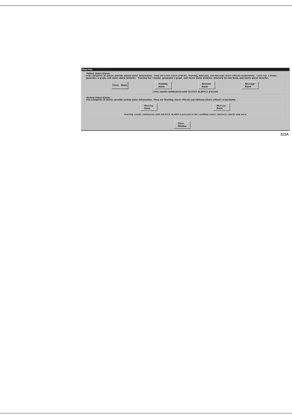
Revision A ApexPro Telemetry System 8-11
2001989-002
Alarm Control: Alarm Control Tab
Alarm Help
For additional information about alarms, click on the Alarm Help button
at the bottom right side of the Alarm Control tab sheet. An Alarm Help
window appears.
You can click on the buttons in this window to hear how each type of
alarm sounds. When you are finished browsing the window, click on the
Close Window button to close the window and return to the single patient
viewer.
Printing Alarm Settings
A telemetry patient’s Alarm Control tab sheet can be printed, showing all
current alarm settings and limits. Click on the Print button in the main
menu to start a printout of the Alarm Control tab sheet.
The Alarm Control tab sheet prints at the Print Window location. For
more information about setting the Print Window location, refer to
Chapter 9, Printing, in this manual.
127(The Alarm Control tab sheet must be the front tab of the single
patient viewer in order to print it. Click on the Alarm Control tab
to bring it to the front if necessary.

8-12 ApexPro Telemetry System Revision A
2001989-002
Alarm Control: Alarm Pause Breakthrough
Alarm Pause Breakthrough
The alarm pause breakthrough feature allows any crisis level alarm to
“break through” (interrupt) an alarm pause and sound at the clinical
information center.
In other words, when this feature is turned on in the Telemetry Unit
Defaults tab sheet, Crisis level alarms will sound at the clinical
information center, even if an alarm pause is in effect.
127(The Alarm Pause Breakthrough feature defaults to Always Off.
It must be set to Always On in the Telemetry Unit Defaults tab
sheet before admitting a telemetry patient if you wish to have
Crisis level alarms break through alarm pauses.
This feature cannot be set on an individual patient basis. It is
either on or off for all telemetry patients admitted to the CIC. A
status message on each patient’s Alarm Control tab sheet
indicates whether it is enabled (on) or disabled (off).
The chart below illustrates the function of the alarm pause breakthrough
feature during the various alarm states.
After a Crisis level alarm has broken through an alarm pause, the
telemetry system does not return to an alarm pause state. All alarms at
any alarm level will sound at the clinical information center.
Alarm State Alarm Pause Breakthrough Function
Alarms on No alarm pause breakthrough; all alarms are on.
Alarms off No alarm pause breakthrough; all alarms are off.
Alarm off reason (X-ray,
shower, etc.) Alarms are paused; Crisis level alarms will break through
the alarm off reason if the patient is in antenna range.
Alarms paused from the
ApexPro transmitter Alarms are paused; Crisis level alarms will break through
the alarm pause.

Revision A ApexPro Telemetry System 8-13
2001989-002
Alarm Control: Alarm Pause Breakthrough
If you wish to continue pausing alarms after an alarm pause
breakthrough occurs, you must re-initiate the alarm pause:
1. To re-initiate an alarms off with reason condition, select the alarms
off reason in the telemetry patient’s Alarm Control tab sheet.
2. To re-initiate an alarm pause from the ApexPro transmitter, press
both transmitter buttons simultaneously twice.
127(The transmitter buttons must be pressed once to “end” the
alarm pause at the transmitter, then a second time to start a
new alarm pause at the transmitter (see below).
The Pause Alarm LED on the ApexPro transmitter continues to flash
after an alarm pause breakthrough occurs. This is because there is no
communication from the clinical information center back to the ApexPro
transmitter to indicate that the alarm pause has ended. After an alarm
pause breakthrough occurs, you can turn off the flashing Pause Alarm
LED by pressing both transmitter buttons simultaneously.

8-14 ApexPro Telemetry System Revision A
2001989-002
Alarm Control: Factory Alarm Default Settings
Factory Alarm Default Settings
Patient Status Alarms
The factory default conditions for each category of alarms are listed
below.
Crisis Alarms Asystole
VFIB/VTAC
Ventricular Tachycardia (V-Tach)
VT > 2
V Brady
Bradycardia (applies only to 0-2 year and 3-10 year age selections)
Warning Alarms Heart rate limits
ST deviation limits
Advisory Alarms Pause
PVC
ACC Vent (accelerated ventricular rhythm)
Tachycardia
Bradycardia (applies only to Adult and 11-13 year age selections)
SPO2
NBP
Message Alarms R-on-T phenomenon
Couplet
Bigeminy
Trigeminy
PVC
Irregular
SPO2 rate

Revision A ApexPro Telemetry System 8-15
2001989-002
Alarm Control: Factory Alarm Default Settings
System Status Alarms
System Warning Alarms
System warning alarms examples:
ARR SUSPEND/ARTIFACT (refer to the appendices)
LEADS FAIL (refer to the appendices)
NO TELEM (refer to the appendices)
System Advisory Alarms System advisory alarms example:
CHANGE BATTERY (refer to the appendices)
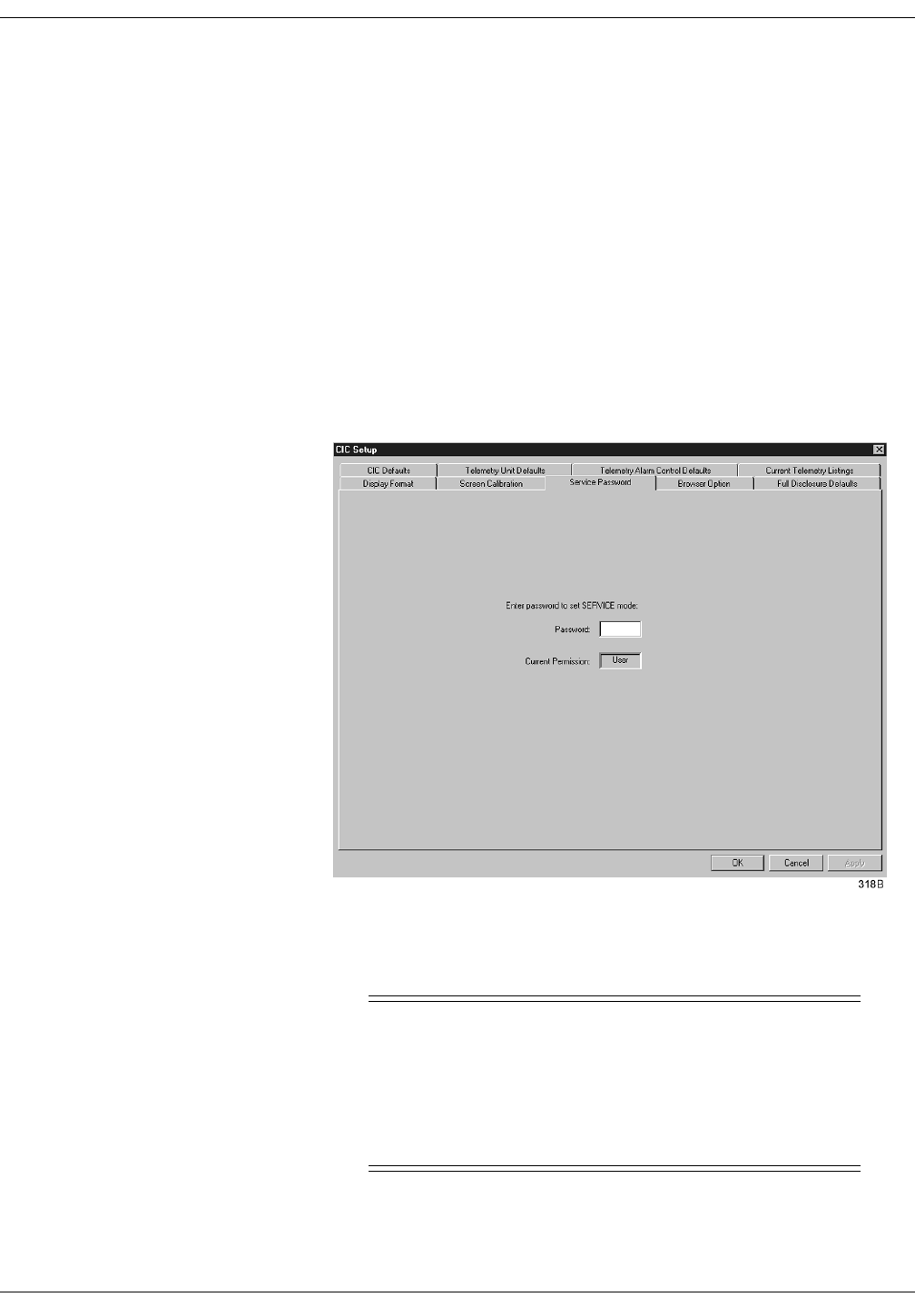
8-16 ApexPro Telemetry System Revision A
2001989-002
Alarm Control: Unit Default Settings for Alarms
Unit Default Settings for Alarms
Telemetry Alarm Control Defaults
You can set Telemetry Unit Defaults for parameter limits and alarm
levels, as well as for arrhythmia alarm levels. These defaults are in effect
for all telemetry patients admitted to your unit, unless they are modified
in an individual patient’s Alarm Control tab sheet (for more information,
see the Alarm Control Tab section in this chapter).
To set telemetry alarm control defaults, follow the steps below:
1. Click on the Setup CIC button at the bottom of the clinical
information center display. A set of tabs appears.
2. Click on the Service Password tab to bring it to the front.
3. Use the keyboard to enter the service password, then click the Apply
button. The Current Permission entry changes from User to Service.
&$87,21
The service mode is intended for use only by qualified
personnel with training and experience in its use. The
consequences of misuse include loss of patient data,
corruption of the clinical information center operating
system software, or disruption of the entire Unity
network.
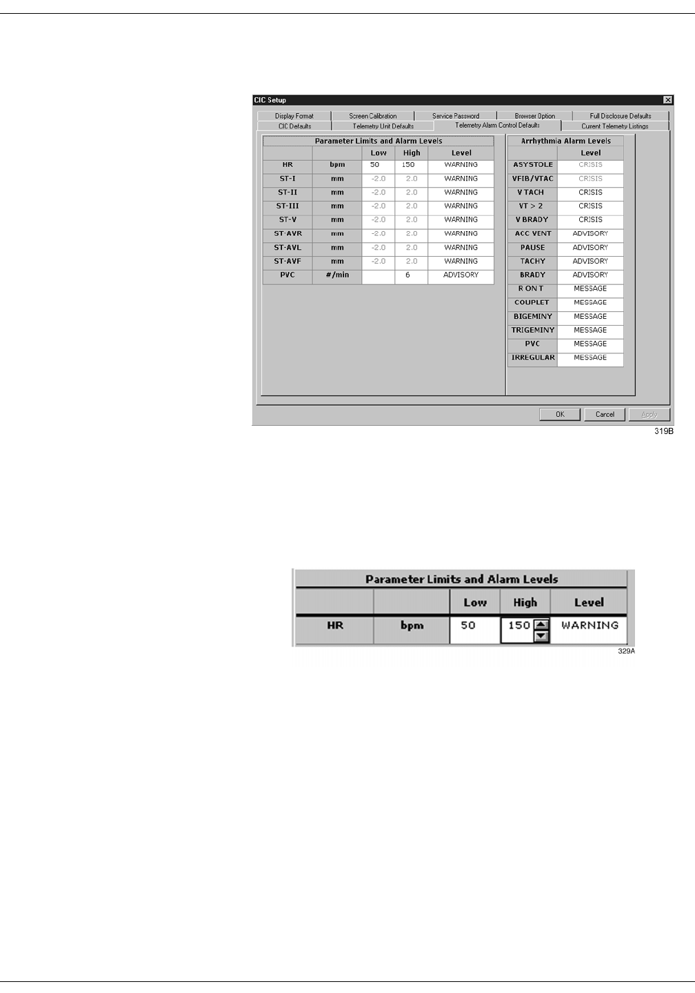
Revision A ApexPro Telemetry System 8-17
2001989-002
Alarm Control: Unit Default Settings for Alarms
4. Click on the Telemetry Alarm Control Defaults tab to bring it to the
front.
Parameter Limits 5. To change the unit defaults for Parameter Limits and Alarm Levels,
use the mouse to click in the Low or High field for the parameter you
wish to edit. The field is framed by a rectangle, and up and down
arrow buttons appear in the field.
6. To increase or decrease the limit by 5, click on the up or down arrow
button.
To increase or decrease the limit in increments other than 5, use the
keyboard to enter a new limit value.
7. Once you have set the desired limit, click on the Apply button for the
changes to take effect.
127(If you make only one change, you do not need to click on the
Apply button. The change will take effect automatically, and
the Apply button will appear dimmed.
8. If you are finished making changes to the Telemetry Alarm Control
Defaults tab sheet, click the OK button.
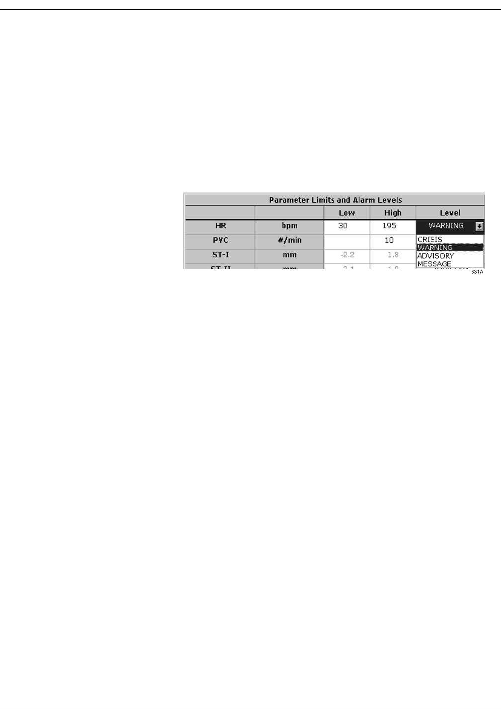
8-18 ApexPro Telemetry System Revision A
2001989-002
Alarm Control: Unit Default Settings for Alarms
Parameter Alarm Levels
To make a change in the telemetry unit default alarm level for a
parameter, first access the Telemetry Alarm Control Defaults tab as
described in the Telemetry Alarm Control Defaults section in this
chapter. Then follow the procedure below.
1. In Telemetry Alarm Control Defaults tab, use the mouse to click in
the Level field of the parameter for which the alarm level is to be
changed. A down arrow button appears in the field.
2. Click on the down arrow button. A popup list of alarm level selections
appears.
3. Click on the desired alarm level to select it.
4. Once you have set the desired level, click the Apply button for the
changes to take effect.
5. If you are finished making changes to the Telemetry Alarm Control
Defaults tab sheet, click the OK button.
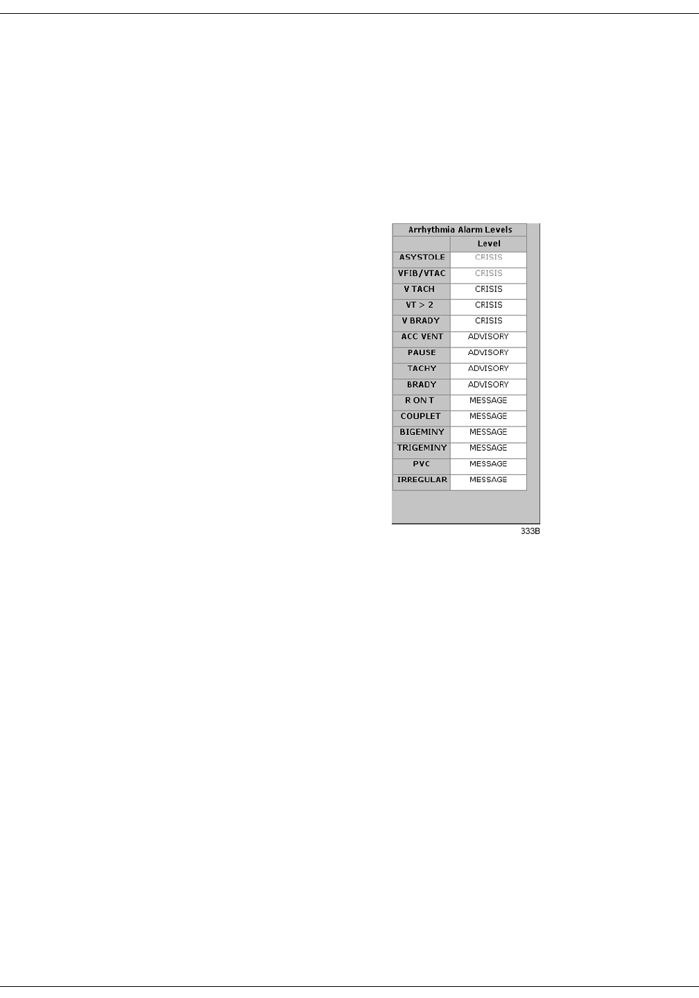
Revision A ApexPro Telemetry System 8-19
2001989-002
Alarm Control: Unit Default Settings for Alarms
Arrhythmia Alarm Levels
To make a change in the telemetry unit default alarm level for
arrhythmia alarms, first access the Telemetry Alarm Control Defaults
tab as described in the Telemetry Alarm Control Defaults section in this
chapter. Then follow the procedure below.
1. In the Telemetry Alarm Control Defaults tab, the arrhythmia alarm
levels for which unit defaults can be set appear on the right side of
the window:
2. Click in the Level field of the arrhythmia alarm you wish to modify. A
down arrow button appears in the field.
127(The arrhythmia alarm levels for ASYSTOLE and VFIB/
VTAC cannot be changed. Therefore, the text in the Level
field for these alarms always appears dimmed.
3. Click on the down arrow button. A popup list of alarm level selections
appears.
4. Click on your choice to select it.
5. Once you have set the desired level, click the Apply button for the
changes to take effect.
If you are finished making changes to the Telemetry Alarm Control
Defaults tab sheet, click the OK button.

8-20 ApexPro Telemetry System Revision A
2001989-002
Alarm Control: Unit Default Settings for Alarms
For your notes

Revision A ApexPro Telemetry System 9-1
2001989-002
9Printing
Initiating a Graph . . . . . . . . . . . . . . . . . . . . . . . . . . . . . . . . . . . . . . . . . . . . . . . . . . . . 9-3
Automatic Alarm Graphs . . . . . . . . . . . . . . . . . . . . . . . . . . . . . . . . . . . . . . . . . . . .9-3
Transmitter Initiated Graphs (Manual Graphs) . . . . . . . . . . . . . . . . . . . . . . . . . . 9-4
Graph Messages . . . . . . . . . . . . . . . . . . . . . . . . . . . . . . . . . . . . . . . . . . . . . . . . . 9-5
Graph All Patients . . . . . . . . . . . . . . . . . . . . . . . . . . . . . . . . . . . . . . . . . . . . . . . . . . . 9-6
Initiating a Graph All Patients Request . . . . . . . . . . . . . . . . . . . . . . . . . . . . . . . . 9-7
Graph Location Defaults . . . . . . . . . . . . . . . . . . . . . . . . . . . . . . . . . . . . . . . . . . . . . . 9-8
Stopping a Graph . . . . . . . . . . . . . . . . . . . . . . . . . . . . . . . . . . . . . . . . . . . . . . . . . . . . 9-9
Graph Paper Out Indicator . . . . . . . . . . . . . . . . . . . . . . . . . . . . . . . . . . . . . . . . . . . 9-10
Graph Setup Tab Sheet . . . . . . . . . . . . . . . . . . . . . . . . . . . . . . . . . . . . . . . . . . . . . . 9-11
Graph Waveforms Controls . . . . . . . . . . . . . . . . . . . . . . . . . . . . . . . . . . . . . . . . .9-11
ECG 1 Control . . . . . . . . . . . . . . . . . . . . . . . . . . . . . . . . . . . . . . . . . . . . . . .9-11
Waveform 2, Waveform 3, and Waveform 4 . . . . . . . . . . . . . . . . . . . . . . . .9-12
Graph Location Controls . . . . . . . . . . . . . . . . . . . . . . . . . . . . . . . . . . . . . . . . . . .9-12
Manual Graph Location . . . . . . . . . . . . . . . . . . . . . . . . . . . . . . . . . . . . . . . .9-12
Alarm Graph Location . . . . . . . . . . . . . . . . . . . . . . . . . . . . . . . . . . . . . . . . .9-12
Print Window Location . . . . . . . . . . . . . . . . . . . . . . . . . . . . . . . . . . . . . . . . .9-12
Enable Transmitter Graph . . . . . . . . . . . . . . . . . . . . . . . . . . . . . . . . . . . . . .9-13
Alarm Graphs Enabled/Disabled . . . . . . . . . . . . . . . . . . . . . . . . . . . . . . . . .9-13
Graph Speed Controls . . . . . . . . . . . . . . . . . . . . . . . . . . . . . . . . . . . . . . . . . . . . .9-14
Laser Printer . . . . . . . . . . . . . . . . . . . . . . . . . . . . . . . . . . . . . . . . . . . . . . . . . . . . . . . 9-15


Revision A ApexPro Telemetry System 9-3
2001989-002
Printing: Initiating a Graph
Initiating a Graph
If you click on a patient’s ECG parameter window, a continuous graph is
initiated for the patient. Clicking on the ECG parameter window again
will stop the graph.
The PRN 50 digital writer and the Direct Digital Writers (DDW) print
patient data (generally referred to as a graph or graph strip). Data can
also be printed on a laser printer.
The waveforms graphed and graph speed are controlled in the individual
patient’s Graph Setup tab sheet. Unit defaults for telemetry patients can
be set in the CIC Defaults tab sheet and the Telemetry Unit Defaults tab
sheet. Refer to Chapter 6, Telemetry Setup, for more information on
setting telemetry unit defaults.
Automatic Alarm Graphs
A graph prints automatically when a patient experiences a Crisis or
Warning alarm condition. Arrhythmia alarm graphs run until the end of
the alarm event. The printer prints up to 10 seconds of data that
occurred immediately before the event, and prints for the duration of the
event. The printer stops printing when the patient returns to a normal
rhythm.
If a printer is not available at the time of the alarm event, a 20-second
graph is saved. This saved graph will print when a printer becomes
available.
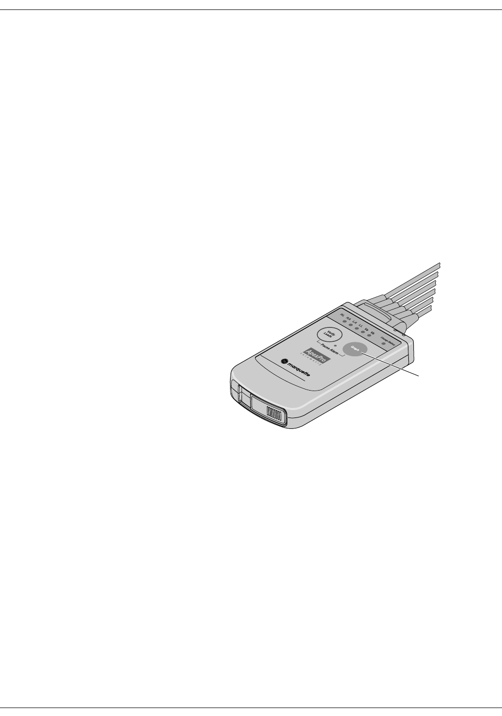
9-4 ApexPro Telemetry System Revision A
2001989-002
Printing: Initiating a Graph
Transmitter Initiated Graphs (Manual Graphs)
When the Graph button on the ApexPro transmitter is pressed, a 20-
second graph strip is printed at a speed of 25 millimeters per second.
When an IMPACT.wf paging system (version II or later) is also available
in the same care unit, pressing the Graph button enables the View on
Demand feature (also called the Apex Graph Button Push feature). The
IMPACT.wf server generates a manually initiated sample page or
snapshot of the patient’s ECG waveform and any other enabled/
monitored non-arrhythmia parameters.
When you press the Graph button on the ApexPro transmitter, it
generates both an IMPACT.wf update page as well as a standard ECG
waveform graph at the clinical information center. The IMPACT.wf page
is labeled “Sample” when this data is displayed on the IMPACT.wf
receiver and stored in history. Additionally, all pagers assigned to the
patient receive a page.
309B
Graph button

Revision A ApexPro Telemetry System 9-5
2001989-002
Printing: Initiating a Graph
Graph Messages
One of the following messages is displayed on the clinical information
center screen during graphing:
GRAPH ALARM—An alarm graph was initiated and is running.
GRAPH MANUAL—A manual graph was requested and is running.
GRAPH TTX—The Graph button on the transmitter was pressed and a
20-second graph strip is running.
PRINTING—A non-real time graph is currently being printed.
SAVING—An alarm or a manual graph has been requested but the
writer is in use; the writer door is open; or the writer is out of paper. The
graph is being saved until the writer is available. (The most recent 20-
second alarm or manual graph will be saved.)

9-6 ApexPro Telemetry System Revision A
2001989-002
Printing: Graph All Patients
Graph All Patients
Clicking on the Print button at the bottom of the clinical information
center display sends a Graph All Patients request to all beds displayed
on the clinical information center, initiating a 10-second graph for each
admitted telemetry patient. When this option is selected for telemetry
patients, graph requests always print at a speed of 25 millimeters per
second.
127(This Graph All Patients function is only available when the
single patient viewer is closed. If a single patient viewer is open,
selecting Print from the main menu initiates a printout of
whichever tab sheet is in front.
The print process stops automatically. If the Graph Stop control key is
pressed on the external DDW, the current patient’s graph stops and the
writer begins to print a 10-second graph for the next patient.
If a patient’s data is currently printing or is being saved to print when a
Graph All Patients request is initiated, this patient’s data will not be
included in the Graph All Patients graph. This patient’s data will print
independently of the Graph All Patients graph.
Clicking on the ECG parameter window for a patient whose data is
saving will cancel the Graph All Patients request for that patient.
If, while a Graph All Patients request is in progress, an arrhythmia
alarm occurs for a patient, the alarm data will replace the data that was
saved for the Graph All Patients request. The alarm data will then
appear on the graph printout.
If, while a Graph All Patients request is running, a telemetry patient
initiates a graph from his or her telemetry transmitter, the saved data
for the Graph All Patients graph will be replaced by data from the
patient’s telemetry transmitter. The data from the telemetry transmitter
will then appear on the graph printout.
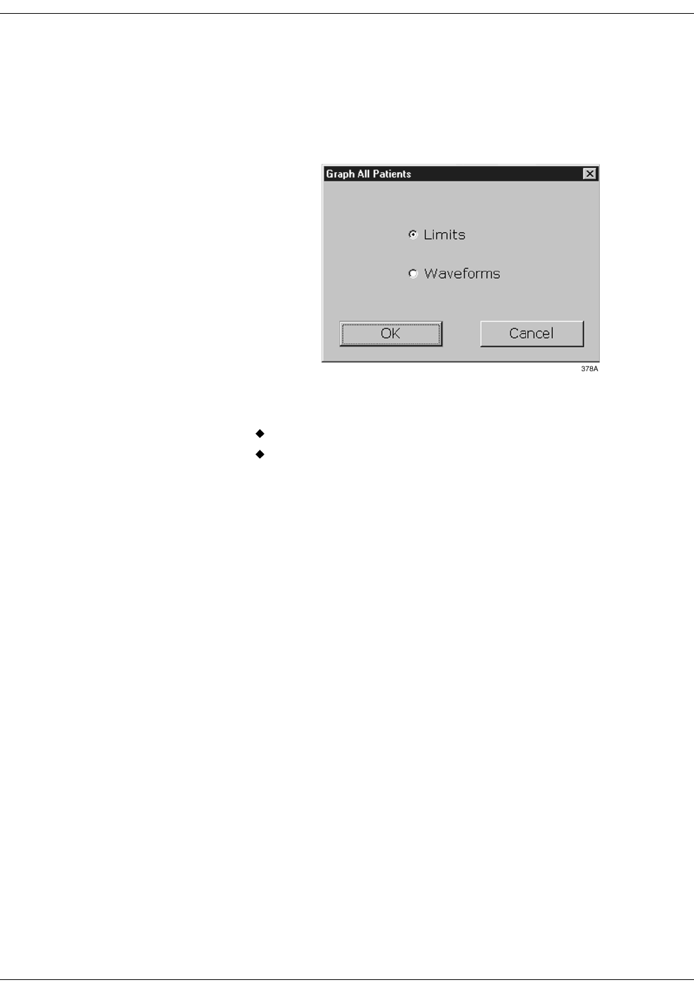
Revision A ApexPro Telemetry System 9-7
2001989-002
Printing: Graph All Patients
Initiating a Graph All Patients Request
To initiate a Graph All Patients request, follow these steps.
1. Click on the Print button at the bottom of the CIC display. The
Graph All Patients window opens.
2. Click on Limits or Waveforms.
Selecting Limits graphs all patient limits.
Selecting Waveforms graphs all patient waveforms.
3. Click on the OK button to complete the Graph All Patients request.

9-8 ApexPro Telemetry System Revision A
2001989-002
Printing: Graph Location Defaults
Graph Location Defaults
Graphs print at the graph locations specified in the patient’s Graph
Setup tab sheet. Upon admission of a patient, these locations are set
from the unit defaults, but they can be modified if desired.
When the patient is no longer displayed at the original clinical
information center (the Admit button is displayed in the waveform
window), the graph default changes to where the patient is
displayed, provided the patient has been moved to another clinical
information center.
If a printer cannot be found at the time of admission for a telemetry
patient, the message Saving No Writer is displayed when a graph is
requested because graphs are not sent to printers outside the unit.
Alarm graphs always print at the patient’s designated alarm graph
location.
Manual graphs and print window requests print at the clinical
information center where the graph was requested, provided that
clinical information center has the same type of writer or printer as
the patient’s set location for that type of graph. If the clinical
information center where the graph was requested does not have the
same type of writer or printer, the graph then prints to the patient’s
specified graph location.
For more information on designating graph locations, refer to the Graph
Location Controls section in this chapter.

Revision A ApexPro Telemetry System 9-9
2001989-002
Printing: Stopping a Graph
Stopping a Graph
To stop a graph request that has been sent to an external writer, press
its Graph Stop control key. This stops any graph already in process. If
this key is pressed when no graph is in process, it advances the paper in
the writer.
127(Because the clinical information center can communicate with
many laser printers, the specific procedure for stopping a graph
sent to a laser printer is not documented in this manual. Refer to
the laser printer manufacturer’s instructions.

9-10 ApexPro Telemetry System Revision A
2001989-002
Printing: Graph Paper Out Indicator
Graph Paper Out Indicator
When there is no graph paper in the writer (or the door is open), the
message Graph Paper Out/Door Open is displayed at the top of the
screen.
When printing to a laser printer, a similar status message is displayed if
the printer is unable to print.
127(Because the clinical information center can communicate with
many laser printers, specific status messages are not
documented in this manual.
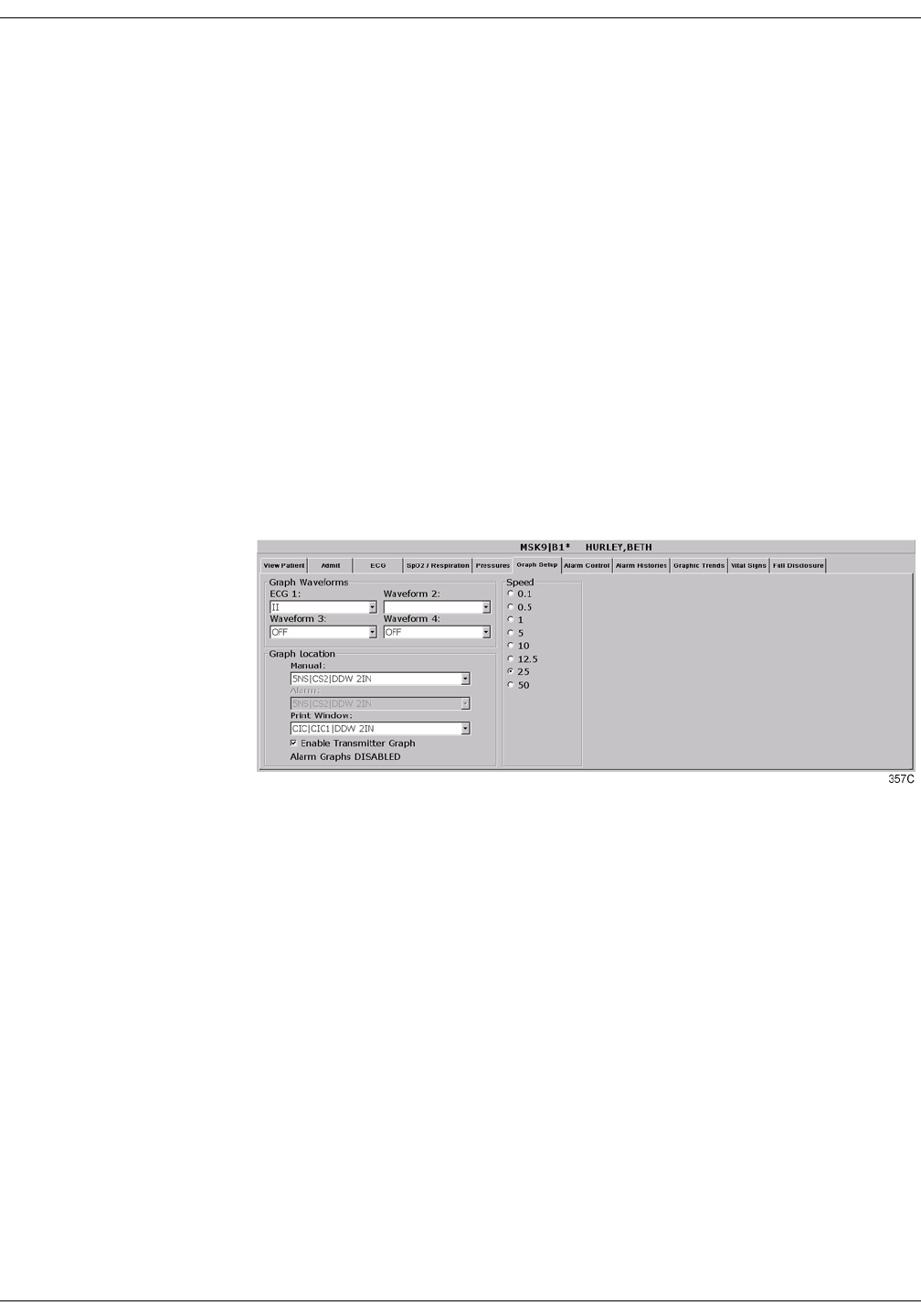
Revision A ApexPro Telemetry System 9-11
2001989-002
Printing: Graph Setup Tab Sheet
Graph Setup Tab Sheet
The Graph Setup tab sheet allows you to define the waveforms to be
graphed, change the graph location and speed, and turn the telemetry
transmitter graph on and off.
127(Changes made in the Graph Setup tab sheet affect only the
patient currently being viewed.
To make changes to graph information for all telemetry patients
in the unit, you must use the CIC Setup and the Telemetry Unit
Defaults tab sheets (refer to Chapter 6, Telemetry Setup, in this
manual).
To view a patient’s Graph Setup tab sheet, follow these steps.
1. Click on the desired patient’s information in the multiple patient
viewer. The single patient viewer for that patient opens.
2. Click on the Graph Setup tab. The Graph Setup tab sheet moves to
the front.
Graph Waveforms Controls
The Graph Waveforms controls allow you designate which waveforms
should print in which positions on a patient’s graph printout.
ECG 1 Control
1. Click in the ECG 1 field. A down arrow button is displayed next to
the waveform currently in the ECG 1 position.
2. Click on the down arrow to display a list of available ECG
waveforms.
3. Click on the desired ECG waveform. The ECG 1 menu closes, with
the selected ECG waveform name remaining visible.

9-12 ApexPro Telemetry System Revision A
2001989-002
Printing: Graph Setup Tab Sheet
Waveform 2, Waveform 3, and Waveform 4
1. Click in the field for the waveform you wish to designate. A down
arrow icon is displayed next to the waveform currently in the
Waveform X position.
127(Waveform X refers to
Waveform 2, Waveform 3, or
Waveform 4, depending on which
field you are in.
2. Click on the down arrow to display a list of available waveforms.
3. Click on the desired waveform. The waveforms menu closes, with the
selected waveform name remaining visible.
Graph Location Controls
The Graph Location controls allow you to set the print destinations for
manual, alarm, and print window graphs.
Manual Graph Location To designate where manual graph requests will print, follow these steps.
1. Click in the Manual field. A down arrow icon is displayed next to the
printer currently designated for printing manual graphs.
2. Click on the down arrow to display a list of available printers.
3. Click on the desired printer. The printers menu closes, with the
selected printer name remaining visible.
Alarm Graph Location
To designate where alarm graphs will print, follow these steps.
1. Click in the Alarm field. A down arrow icon is displayed next to the
printer currently designated for printing alarm graphs.
2. Click on the down arrow to display a list of available printers.
3. Click on the desired printer. The printers menu closes, with the
selected printer name remaining visible.
Print Window Location
To designate where print window requests will print, follow these steps.
1. Click in the Print Window field. A down arrow icon is displayed next
to the printer currently designated for printing alarm graphs.
2. Click on the down arrow to display a list of available printers.
3. Click on the desired printer. The printers menu closes, with the
selected printer name remaining visible.
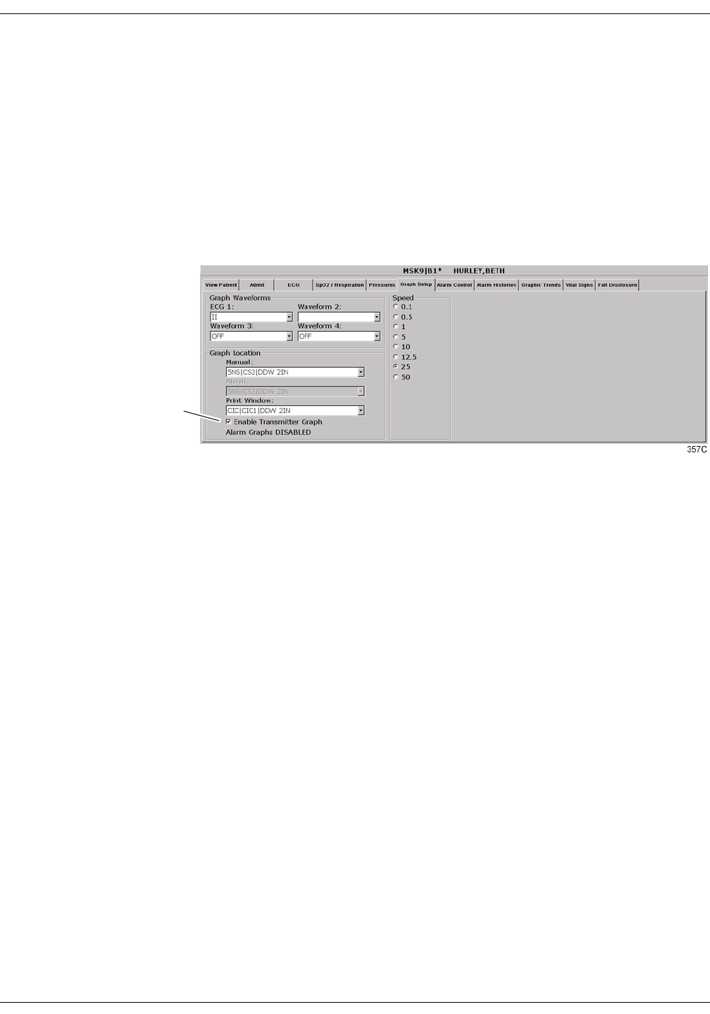
Revision A ApexPro Telemetry System 9-13
2001989-002
Printing: Graph Setup Tab Sheet
Enable Transmitter Graph
The Enable Transmitter Graph option allows you to turn off/on the
transmitter graph function for telemetry patients. When this option is
enabled, a telemetry patient can initiate a graph by pressing the Graph
button on the ApexPro transmitter. When this option is disabled, no
graph can be initiated. To enable or disable this option, follow this
procedure:
1. To enable the transmitter graph option, point and click with the
mouse to place a check mark in the Enable Transmitter Graph check
box.
2. To disable the transmitter graph option, point and click with the
mouse to remove the check mark in the Enable Transmitter Graph
check box.
Alarm Graphs Enabled/Disabled
This message line indicates whether the graph on alarm feature is on
(Alarm Graph ENABLED) or off (Alarm Graph DISABLED). This
feature cannot be set on an individual patient basis. Use the Alarm
Graph option in the Telemetry Unit Defaults tab sheet to set it for all
patients admitted to the CIC.
Enable Transmitter
Graph
Check Box

9-14 ApexPro Telemetry System Revision A
2001989-002
Printing: Graph Setup Tab Sheet
Graph Speed Controls
The graph Speed controls allow you to adjust the speed at which a graph
prints (mm/s). Simply click on the desired speed.

Revision A ApexPro Telemetry System 9-15
2001989-002
Printing: Laser Printer
Laser Printer
A laser printer can be connected to the back of the clinical information
center. (Refer to the service manual for more information on printer
connections.) The clinical information center must be formatted for a
laser printer upon installation in order for a laser printer to function
with it. Refer to the service manual for the clinical information center for
more information.
Printing to a laser printer for a telemetry patient may be configured on
an individual basis or set up as a unit default. For more information,
refer to the Graph Setup Tab Sheet section in this chapter, and to
Chapter 6, Telemetry Setup, in this manual.
You can send all information that can currently be formatted for a writer
to a laser printer at the clinical information center.
To graph information to a laser printer at the clinical information center,
select the laser printer under the Graph Location controls in the Graph
Setup tab sheet.

9-16 ApexPro Telemetry System Revision A
2001989-002
Printing: Laser Printer
For your notes

Revision A ApexPro Telemetry System 10-1
2001989-002
10 Patient Data
Introduction . . . . . . . . . . . . . . . . . . . . . . . . . . . . . . . . . . . . . . . . . . . . . . . . . . . . . . . 10-3
Alarm Histories . . . . . . . . . . . . . . . . . . . . . . . . . . . . . . . . . . . . . . . . . . . . . . . . . . . . 10-4
Event Directory . . . . . . . . . . . . . . . . . . . . . . . . . . . . . . . . . . . . . . . . . . . . . . . . . .10-4
Event Window . . . . . . . . . . . . . . . . . . . . . . . . . . . . . . . . . . . . . . . . . . . . . . . . . . .10-5
Alarm Histories Buttons . . . . . . . . . . . . . . . . . . . . . . . . . . . . . . . . . . . . . . . . . . . .10-5
Scan Newer Events . . . . . . . . . . . . . . . . . . . . . . . . . . . . . . . . . . . . . . . . . . .10-5
Scan Older Events . . . . . . . . . . . . . . . . . . . . . . . . . . . . . . . . . . . . . . . . . . . .10-5
Print Directory . . . . . . . . . . . . . . . . . . . . . . . . . . . . . . . . . . . . . . . . . . . . . . .10-5
View Newer Event . . . . . . . . . . . . . . . . . . . . . . . . . . . . . . . . . . . . . . . . . . . .10-5
View Older Event . . . . . . . . . . . . . . . . . . . . . . . . . . . . . . . . . . . . . . . . . . . . .10-6
Delete Event . . . . . . . . . . . . . . . . . . . . . . . . . . . . . . . . . . . . . . . . . . . . . . . .10-6
Learn As . . . . . . . . . . . . . . . . . . . . . . . . . . . . . . . . . . . . . . . . . . . . . . . . . . . .10-6
Relearn . . . . . . . . . . . . . . . . . . . . . . . . . . . . . . . . . . . . . . . . . . . . . . . . . . . .10-7
Graphic Trends . . . . . . . . . . . . . . . . . . . . . . . . . . . . . . . . . . . . . . . . . . . . . . . . . . . . 10-8
Trend Directory Window . . . . . . . . . . . . . . . . . . . . . . . . . . . . . . . . . . . . . . . . . . .10-9
Cursor . . . . . . . . . . . . . . . . . . . . . . . . . . . . . . . . . . . . . . . . . . . . . . . . . . . . . . . . .10-9
Time Resolution Menu . . . . . . . . . . . . . . . . . . . . . . . . . . . . . . . . . . . . . . . . . . . 10-10
Graphic Trends Buttons . . . . . . . . . . . . . . . . . . . . . . . . . . . . . . . . . . . . . . . . . . .10-10
Deselect All . . . . . . . . . . . . . . . . . . . . . . . . . . . . . . . . . . . . . . . . . . . . . . . .10-10
Scan Older . . . . . . . . . . . . . . . . . . . . . . . . . . . . . . . . . . . . . . . . . . . . . . . . .10-10
Scan Newer . . . . . . . . . . . . . . . . . . . . . . . . . . . . . . . . . . . . . . . . . . . . . . . .10-10
Arrow Keys . . . . . . . . . . . . . . . . . . . . . . . . . . . . . . . . . . . . . . . . . . . . . . . . .10-11
Printing Graphic Trends . . . . . . . . . . . . . . . . . . . . . . . . . . . . . . . . . . . . . . . . . . .10-11
Vital Signs . . . . . . . . . . . . . . . . . . . . . . . . . . . . . . . . . . . . . . . . . . . . . . . . . . . . . . . 10-12
Sort Mode . . . . . . . . . . . . . . . . . . . . . . . . . . . . . . . . . . . . . . . . . . . . . . . . . . . . .10-12
Increment . . . . . . . . . . . . . . . . . . . . . . . . . . . . . . . . . . . . . . . . . . . . . . . . . . . . . .10-13
Scroll Bars . . . . . . . . . . . . . . . . . . . . . . . . . . . . . . . . . . . . . . . . . . . . . . . . . . . . .10-13
Printing Vital Signs . . . . . . . . . . . . . . . . . . . . . . . . . . . . . . . . . . . . . . . . . . . . . . .10-13
Full Disclosure . . . . . . . . . . . . . . . . . . . . . . . . . . . . . . . . . . . . . . . . . . . . . . . . . . . . 10-14
Full Disclosure Options . . . . . . . . . . . . . . . . . . . . . . . . . . . . . . . . . . . . . . . . . . .10-14
Speed . . . . . . . . . . . . . . . . . . . . . . . . . . . . . . . . . . . . . . . . . . . . . . . . . . . . .10-14
Scan Older . . . . . . . . . . . . . . . . . . . . . . . . . . . . . . . . . . . . . . . . . . . . . . . . .10-14
Scan Newer . . . . . . . . . . . . . . . . . . . . . . . . . . . . . . . . . . . . . . . . . . . . . . . .10-15
Older Event . . . . . . . . . . . . . . . . . . . . . . . . . . . . . . . . . . . . . . . . . . . . . . . .10-15
Newer Event . . . . . . . . . . . . . . . . . . . . . . . . . . . . . . . . . . . . . . . . . . . . . . .10-15
View All ECG/Monitor . . . . . . . . . . . . . . . . . . . . . . . . . . . . . . . . . . . . . . . .10-15
Print Report . . . . . . . . . . . . . . . . . . . . . . . . . . . . . . . . . . . . . . . . . . . . . . . .10-15
Time Focus . . . . . . . . . . . . . . . . . . . . . . . . . . . . . . . . . . . . . . . . . . . . . . . . . . . . . . . 10-16


Revision A ApexPro Telemetry System 10-3
2001989-002
Patient Data: Introduction
Introduction
For the purposes of this manual, patient data consists of the information
presented within these tab sheets:
Alarm Histories
Graphic Trends
Vital Signs
Full Disclosure
Once a patient is admitted to the clinical information center, a history of
the patient’s vital signs is continually collected. The most recent 24 hours
of data can be viewed in a tabular format (vital signs) or in a graphic
format (graphic trends).
Every non-episodic parameter is sampled every two seconds. A median
value is determined, and that value is stored for display at one-minute
resolution. Episodic parameters (NBP, etc.) are stored every time one
occurs. If more than one episodic event occurred during the same minute,
the more recent event will overwrite the earlier one.
Alarm histories for arrhythmia events are recorded and stored, up to a
maximum of 100 events (36 events in Combo mode) per patient.
When full disclosure is turned on, complete ECG data for each patient is
recorded and stored for viewing.
You cannot change any patient data values, but you can use the controls
to view all the data collected.
Patient data can be viewed in varying time scales and can be printed to a
connected laser printer or a writer.
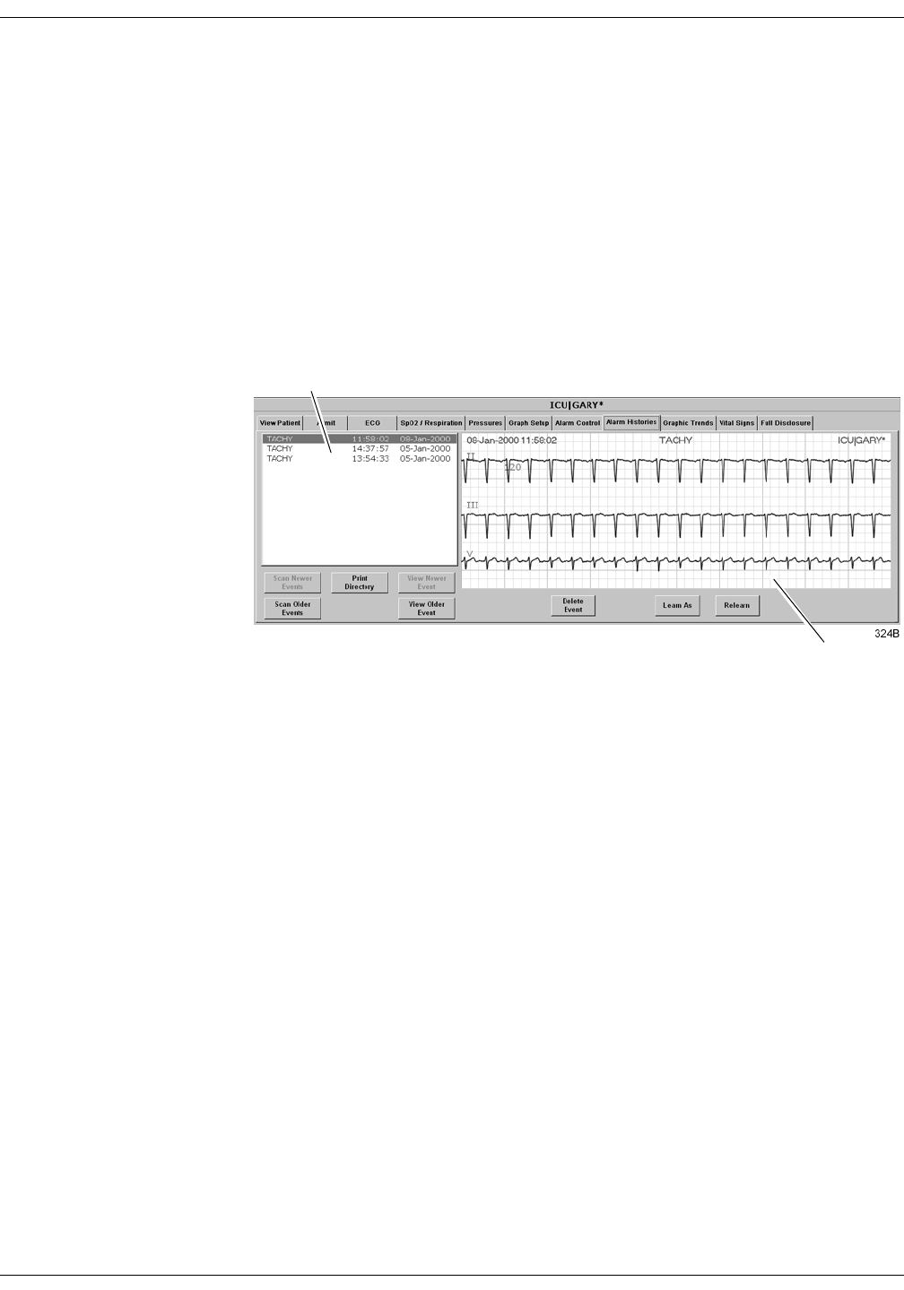
10-4 ApexPro Telemetry System Revision A
2001989-002
Patient Data: Alarm Histories
Alarm Histories
A patient’s arrhythmia events are stored in Alarm Histories, and can be
reviewed, printed, and deleted at the clinical information center. To
access a patient’s Alarm Histories tab sheet, follow the instructions
below.
1. Click in the bed window of the patient whose Alarm Histories you
wish to view. The clinical information center display rearranges to
accommodate the single patient viewer at the bottom of the display.
2. In the single patient viewer, click on the Alarm Histories tab,
bringing it to the front.
The Alarm Histories tab sheet contains an event directory (a list of
arrhythmia events recorded) for the patient, and an event window for
viewing individual events. It also contains several buttons, which control
the functions available in Alarm Histories. These functions are described
in this chapter.
Event Directory
An event directory appears on the left side of the Alarm Histories tab.
This directory is a list of all arrhythmia events that have occurred for
this particular patient.
A maximum of 100 events is stored for each patient (36 events in the
Combo monitoring mode). After 100 events have been stored, the oldest
event is deleted to make room for any new event that occurs.
Approximately 10 events can be seen in the event directory at one time.
There are two ways to access events that are not currently visible in the
event directory. You can use the mouse and the scroll bar on the right
side of the event directory to scroll up and down through all the events,
or you can use the Scan Newer Events and/or Scan Older Events buttons.
How to use these two buttons is discussed later in this chapter.
Event Directory
Event Window

Revision A ApexPro Telemetry System 10-5
2001989-002
Patient Data: Alarm Histories
Event Window
The event window appears on the right side of the Alarm Histories tab
sheet. The event shown in the event window corresponds to the event
that is highlighted in the event directory. The date, time, and name of
the event are shown in the event window header.
The event window displays 10 seconds of the patient’s ECG waveform
that was recorded when the event occurred. It displays up to three leads
that were being monitored at the time the event occurred. For an ST
event, the alarm ST event is displayed, along with a superimposed ST
template for reference purposes.
To print an event shown in the event window, use the mouse to click on
the Print button in the Main Menu at the bottom of the clinical
information center. One event is printed per page.
Alarm Histories Buttons
There are eight buttons that perform various functions in the Alarm
Histories tab. They are described below.
Scan Newer Events Click on the Scan Newer Events button to move through all events in the
event directory that are newer than the event that is currently
highlighted. If there are no events newer than the highlighted event, this
button is dimmed and does not function. This button changes to STOP
when a scan is in process. To stop a scan, click on the button again. While
the scan is in progress, you can also select Scan Older Events to reverse
the scanning direction.
Scan Older Events Click on the Scan Older Events button to move through all events in the
event directory that are older than the event that is currently
highlighted. If there are no events older than the highlighted event, this
button is dimmed and does not function. This button changes to STOP
when a scan is in process. To stop a scan, click on the button again. While
the scan is in progress, you can also select Scan Newer Events to reverse
the scanning direction.
Print Directory Click on the Print Directory button to print a list of all events currently
stored in the event directory. The list prints at the Print Window graph
default location.
View Newer Event Click on the View Newer Event button to view the next newer event
waveforms, if any. If there are no events newer than the highlighted
event, this button is dimmed and does not function.

10-6 ApexPro Telemetry System Revision A
2001989-002
Patient Data: Alarm Histories
View Older Event Click on the View Older Event button to view the next older event
waveforms, if any. If there are no events older than the highlighted
event, this button is dimmed and does not function.
Delete Event Click on the Delete Event button to delete the event that is currently
highlighted in the event directory. This cannot be undone.
If more than one event is highlighted (using Shift or Ctrl and the mouse),
a message appears when you press the Delete Event button, asking if you
are sure you wish to delete the events. Click on Ok to continue the delete.
Learn As The Learn As button is used to indicate to the clinical information center
that the arrhythmia algorithm the telemetry patient is in is a “normal”
rhythm for this patient.
This changes the name of the arrhythmia call on the template in the
alarm history. The new name is displayed with an “*---*” to indicate it
has been renamed.
127(If a call name is changed via this option, it only applies to
subsequent occurrences of this call. It will not change the names
of calls stored in history before the change was made.
Once Learn As is used for an active template, the arrhythmia
algorithm will adhere to that change.
:$51,1*
Do not use the Learn As feature for rhythms that include
true ventricular beats in the 10 second history. This
could affect the ventricular template, depending on its
relation to the beats involved in the arrhythmia call.
The following rhythm categories allow user feedback to reclassify
arrhythmia calls:
127(This feature does not correct noise-related arrhythmia calls.
Address noise-related arrhythmia calls with proper skin
preparation and electrode placement.
Category Description Limitations
NORMAL Used when the patient is normally in a paced rhythm and
then has an early and wide beat or rhythm that is the
patient’s normal rhythm.
Disallowed when the heart rate of the ventricular
beats exceeds the high heart rate limit.
ABERRANT Used when the system is alarming as a VTach or
Accelerated Ventricular arrhythmia.
The rhythm is most likely a bundle branch block.
Disallowed when the heart rate of the ventricular
beats exceeds the high heart rate limit.
AFIB (Atrial Fibrillation) Used when the system is alarming for an irregular rhythm,
for example.
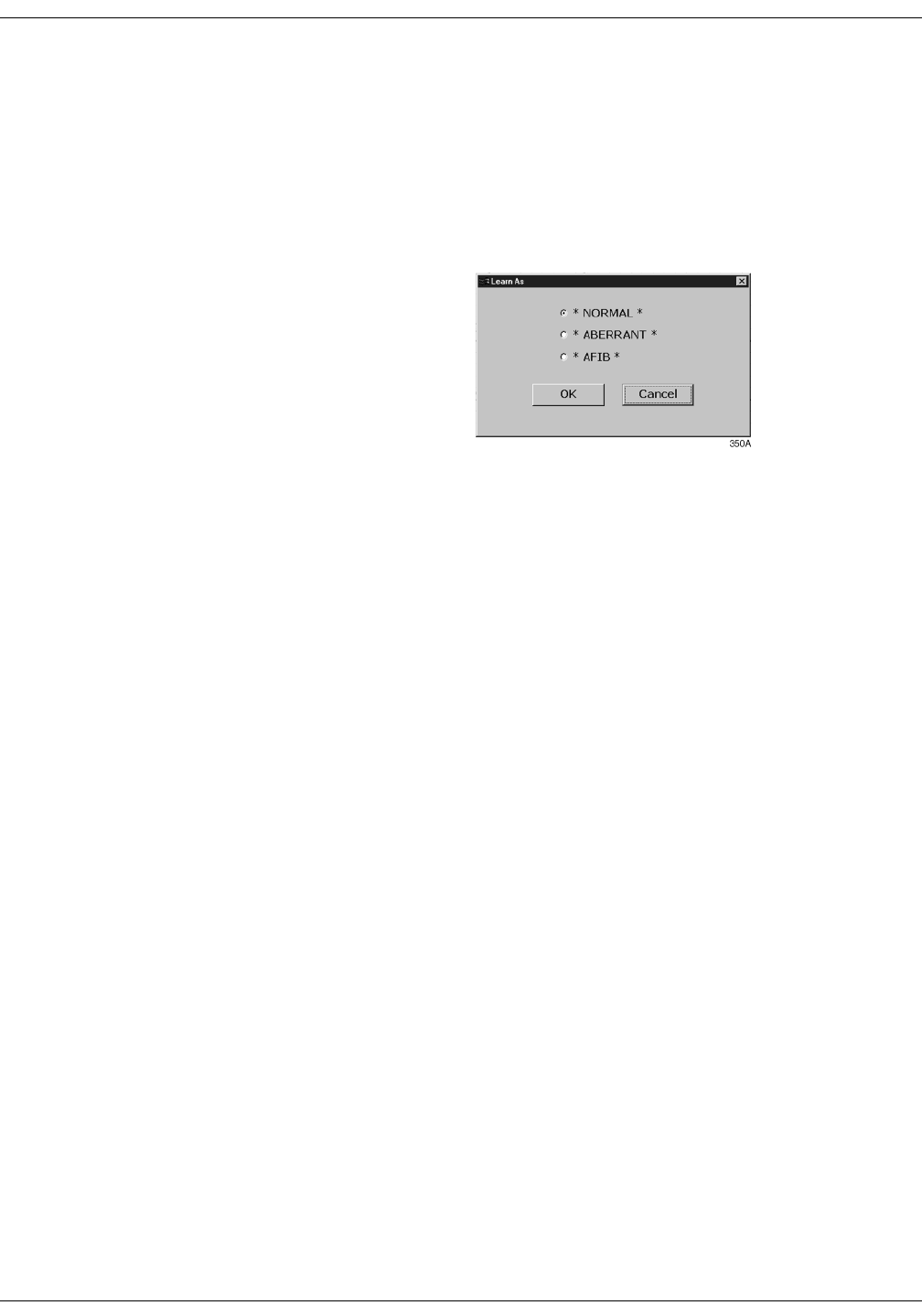
Revision A ApexPro Telemetry System 10-7
2001989-002
Patient Data: Alarm Histories
Changing the Name of an Arrhythmia Call
1. To change the name of an arrhythmia call, display the alarm history
for the event that is in question by clicking on that event in the event
directory.
2. Click on the Learn As button in the Alarm Histories tab.
3. The Learn As dialog box opens, providing the list of new names to
apply to the rhythm.
4. Click on the radio button to select the new name choice for the call.
The alarm history will be updated, and the new name for the call is
marked with “*---*” to indicate that it has been renamed.
127(The Relearn option is available in the Alarm Histories tab, the
ECG tab, and the View Patient tab. If selected, it will clear the
patient’s waveforms and all templates. When all of the templates
are cleared, all renamed calls will revert to their original names,
and the Learn As intervention is nullified.
If you try to apply a template that is no longer active, a
“Template Inactive” message will be displayed, and the
arrhythmia call in question will not be renamed.
Relearn Select the Relearn button to initiate a relearn procedure. A relearn will
clear the patient’s waveforms and templates, and learn the patient’s
current rhythm as the dominant, “normal” rhythm.
Relearn is useful when you have changed a patient’s electrodes or
leadwires, or when it appears that false alarm calls are being made by
the arrhythmia program. The relearn takes only a few seconds.
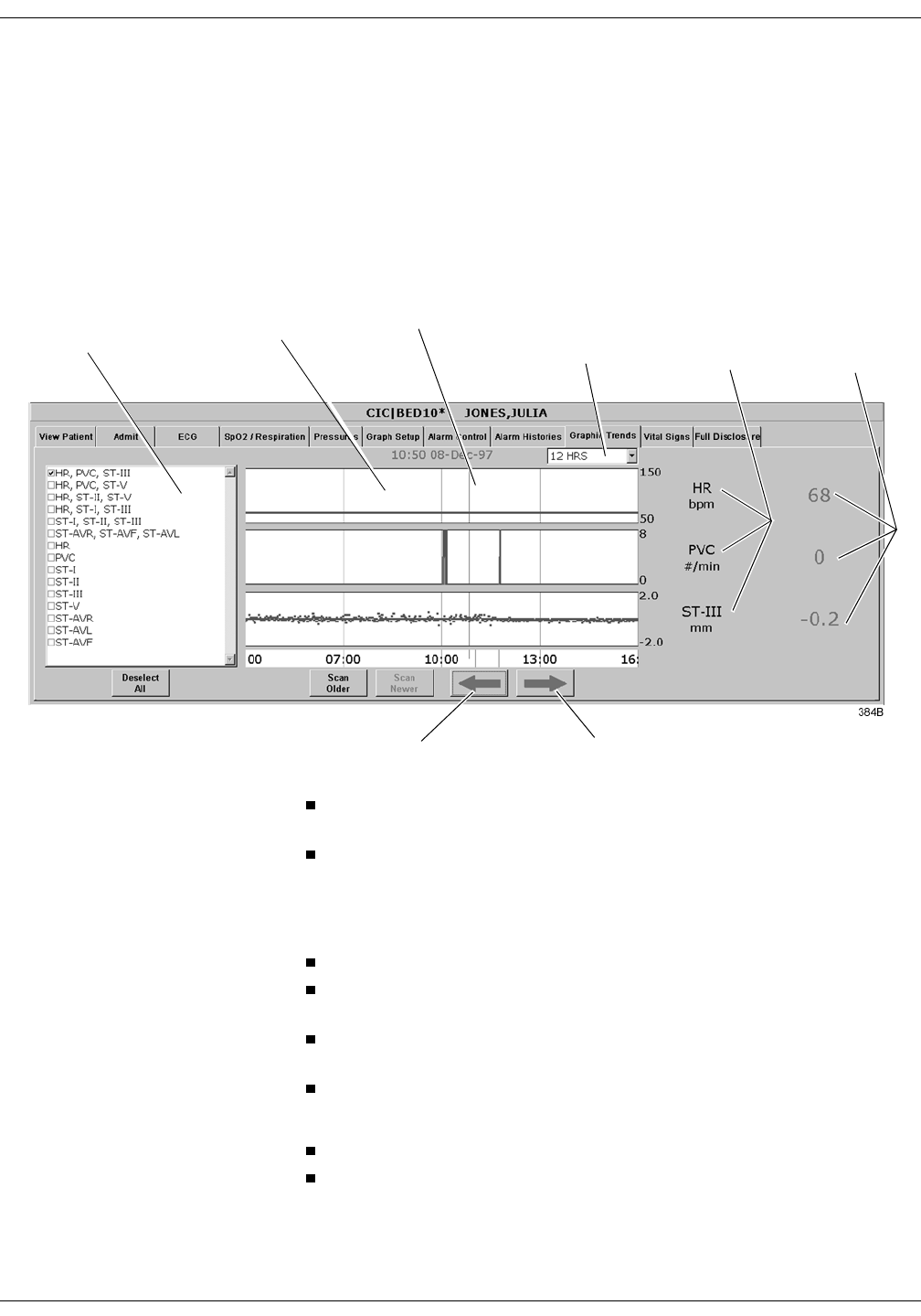
10-8 ApexPro Telemetry System Revision A
2001989-002
Patient Data: Graphic Trends
Graphic Trends
To view a patient’s graphic trends, follow these steps.
1. Click on the desired patient’s bed window in the multiple patient
viewer. The single patient viewer for that patient opens.
2. Click on the Graphic Trends tab in the single patient viewer. The
Graphic Trends tab sheet moves to the front.
The Trend Directory window lists trends and preset trend
combinations for display.
The Graphic Trends window displays the selected graphic trends in
blue.
127(Data points that go off the scale are shown at the graticule
limit in red, not in the usual blue.
Deselect All “turns off” all currently selected graphic trends.
The cursor shows the locations on the graphic trend corresponding
with numeric values.
Arrow keys move the cursor right or left, showing older or newer
trend values.
The Time Resolution menu is a popup menu to adjust the time
resolution for displayed trend data.
127(After either Scan Older or
Scan Newer is selected, the button
label changes to STOP.
Scan Older scans older data.
Scan Newer scans newer data.
Trend Directory
Window Graphic Trends
Window
Graphic
Trend Labels Numeric
Values at the
Cursor
Time
Resolution
Menu
Shows Newer
Graphic Trends
Shows Older
Graphic Trends
Cursor
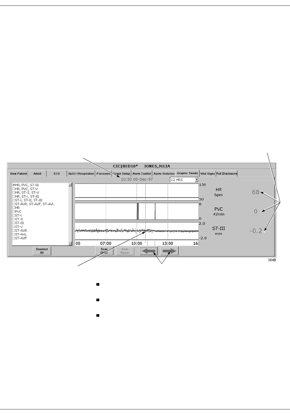
Revision A ApexPro Telemetry System 10-9
2001989-002
Patient Data: Graphic Trends
Trend Directory Window
Up to three graphic trend plots can be displayed in the Graphic Trends
window at one time. You can select from preset groupings of trends or
individual trends.
To select the trends for display in the Graphic Trends window, click on a
preset trend grouping or individual trends (up to three). When selected, a
check appears in the box to the left of the label.
Cursor
One-minute median values can be accessed through the use of a cursor at
the clinical information center.
The default cursor location is at the current time when entering the
Graphic Trends tab sheet.
You can move the cursor to any median value and review the actual
numeric data.
The cursor is not printed with the graphic trend data.
Cursor
Time and Date
Corresponding to
Cursor Position
Arrow Keys Move Cursor
Numeric Values at
the Cursor

10-10 ApexPro Telemetry System Revision A
2001989-002
Patient Data: Graphic Trends
Time Resolution Menu
In the Graphic Trends tab sheet, you can define the amount of trend data
(resolution) to display in the trend window. This is done with the popup
menu located to the right of the time and date.
1. Click on the down arrow to display the time options.
2. Click on the desired time resolution. The time resolution menu
closes, with the selected resolution remaining visible. The selected
time resolution is also reflected immediately in the Graphic Trends
window.
Graphic Trends Buttons
There are five buttons that perform various functions in the Graphic
Trends tab. The function of each button is described below.
Deselect All Click on the Deselect All button to clear all trends from the Graphic
Trends window. Selecting this option also removes any checks from the
Trend Directory window.
Scan Older Click on the Scan Older button to initiate a scan of older trend data.
When clicked, the scan begins and older trend data scrolls across the
display. While the scan is in progress, you can select Scan Newer to
reverse the scanning direction.
This button changes to STOP when a scan is in process. Click on the
STOP button to stop a scan in process. When the oldest event is
displayed, the scan automatically stops, and the label on this button will
be dimmed.
Scan Newer Click on the Scan Newer button to initiate a scan of newer trend data.
When clicked, the scan begins and newer trend data scrolls across the
display. While the scan is in progress, you can select Scan Older to
reverse the scanning direction.
This button changes to STOP when a scan is in process. Click on the
STOP button to stop a scan in process. When the most recent event is
displayed, the scan automatically stops, and the label on this button will
be dimmed.

Revision A ApexPro Telemetry System 10-11
2001989-002
Patient Data: Graphic Trends
Arrow Keys Clicking the left arrow moves the cursor one minute in the “older”
direction. When the oldest (least recent) event is displayed, the left arrow
is dimmed.
Clicking the right arrow moves the cursor one minute in the “newer”
direction. When the newest (most recent) event is displayed, the right
arrow is dimmed.
Printing Graphic Trends
Trends can be printed using the same time scale as the display. To print
a graphic trend, click on the Print button at the bottom of the CIC
display.
Graphic trend printouts for telemetry patients can be printed to a laser
printer or to a writer. Graphic trends print to the Print Window default
printer location.
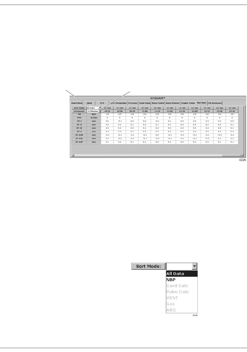
10-12 ApexPro Telemetry System Revision A
2001989-002
Patient Data: Vital Signs
Vital Signs
To view a patient’s vital signs, follow these steps.
1. Click in the desired patient’s bed window in the multiple patient
viewer. The single patient viewer for that patient opens.
2. Click on the Vital Signs tab in the single patient viewer. The Vital
Signs tab sheet moves to the front. The Vital Signs tab sheet displays
periodic and episodic trend data in tabular, or spreadsheet, form.
127(When a telemetry patient’s vital signs are printed to a Direct
Digital Writer, the anchor column (the column closest to the time
interval selected) and four additional columns print, based on the
time interval selected.
Printed data may be delayed by one minute from the displayed
data due to time of request and update of trend files.
Sort Mode
The Sort Mode popup menu provides options for sorting the way vital
signs data is viewed. If the telemetry patient is being monitored for NBP,
the sort options are All Data and NBP. If the patient is not being
monitored for NBP, the only option available is All Data. All other sort
options appear dimmed.
Sort Mode
Menu
Increment
Menu

Revision A ApexPro Telemetry System 10-13
2001989-002
Patient Data: Vital Signs
Increment
In the Vital Signs tab sheet, you can define the amount of data
(resolution) to display in the Vital Signs window. This is done with the
Increment popup menu.
1. Click on the down arrow to display all of the Increment options.
2. Click on the desired increment. The Increment menu closes, with the
selected increment remaining visible. The selected increment is also
reflected immediately in the Vital Signs window.
Scroll Bars
If all of the Vital Signs data does not fit into the available display space,
use the scroll bars to navigate among columns and rows of data. For
more information on using scroll bars, refer to the Clinical Information
Center Operator’s Manual.
Printing Vital Signs
Displayed trends can be printed using the same time scale as the display.
To print a graphic trend, click on the Print button at the bottom of the
CIC display.
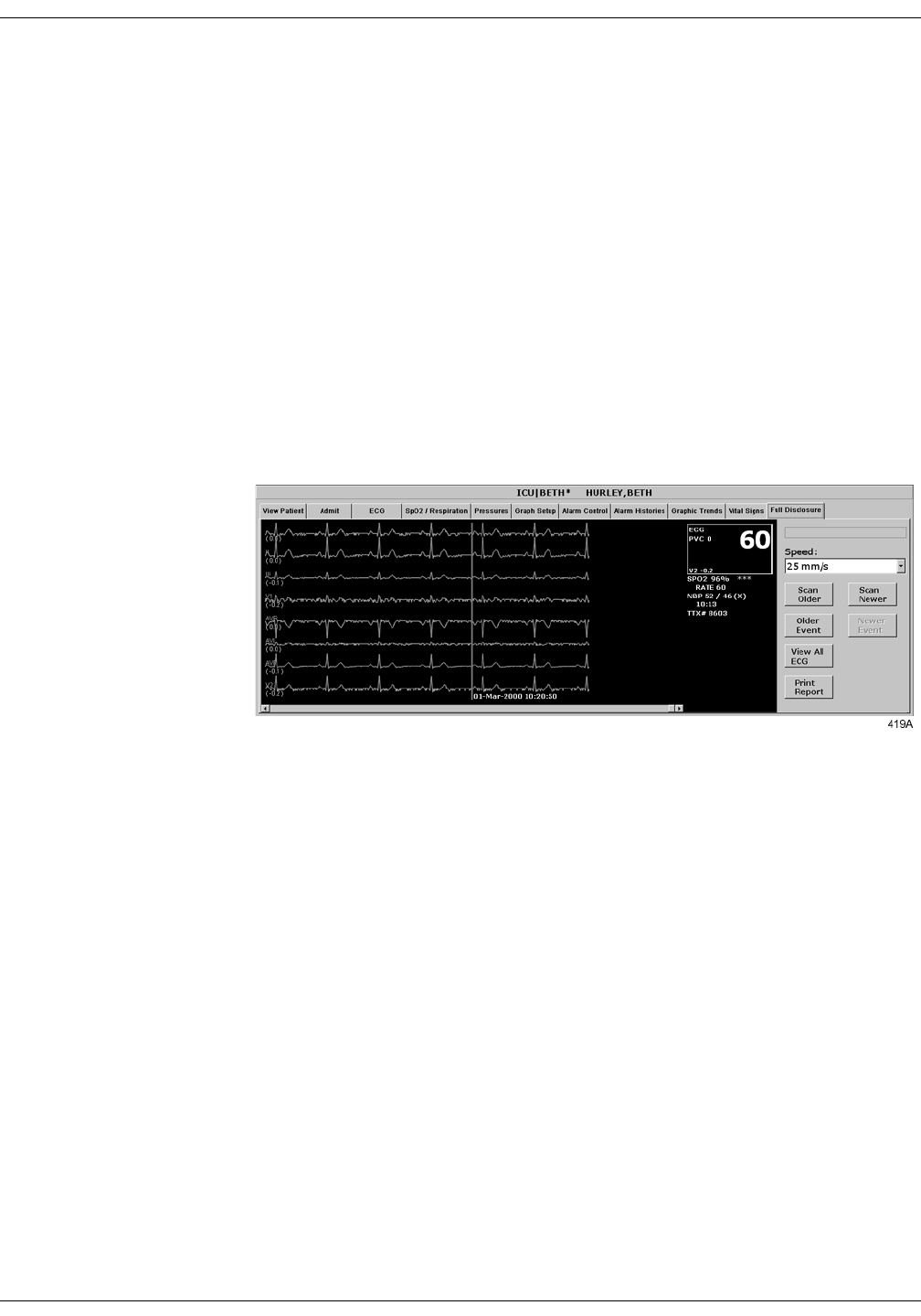
10-14 ApexPro Telemetry System Revision A
2001989-002
Patient Data: Full Disclosure
Full Disclosure
127(This section provides a brief overview of the Full Disclosure
function. Refer to the Clinical Information Center Operator’s
Manual for detailed information.
The full disclosure feature must be enabled in the Full Disclosure
Defaults tab sheet. Refer to the Clinical Information Center operator’s
manual for details on enabling this feature.
When full disclosure is enabled, follow these steps to view a patient’s Full
Disclosure window.
1. Click in the desired patient’s bed window in the multiple patient
viewer. The single patient viewer for that patient opens.
2. Click on the Full Disclosure tab in the single patient viewer. The Full
Disclosure tab sheet moves to the front.
Full Disclosure Options
Speed The Speed popup list allows you to set the waveform compression for the
full disclosure waveform display.
Scan Older Clicking on the Scan Older button initiates a scan of older full disclosure
data. When the button is clicked, the scan begins and older trend data
scrolls across the display. While the scan is in progress, you can select
Scan Newer to reverse the scanning direction.
This button changes to STOP when a scan is in process. Click on the
STOP button to stop a scan in process. When the oldest data is displayed,
the scan automatically stops and the label on this button will be dimmed.

Revision A ApexPro Telemetry System 10-15
2001989-002
Patient Data: Full Disclosure
Scan Newer Clicking on the Scan Newer button initiates a scan of newer full
disclosure data. When the button is clicked, the scan begins and newer
data scrolls across the display. While the scan is in progress, you can
select Scan Older to reverse the scanning direction.
This button changes to STOP when a scan is in process. Click on the
STOP button to stop a scan in process. When the newest data is
displayed, the scan automatically stops and the label on this button will
be dimmed.
Older Event Clicking on the Older Event button moves the cursor to the next older
alarm history event.
Newer Event Clicking on the Newer Event button moves the cursor to the next most
recent alarm history event.
View All ECG/Monitor This option switches between View All ECG and Monitor. The View All
ECG option displays all ECG waveforms. The Monitor option displays all
waveforms that are displayed at the bedside at the time of full disclosure.
In the case of telemetry patients, these are the same, since only ECG
waveforms are displayed for telemetry patients.
Print Report Clicking on the Print Report button initiates a full disclosure report
printout. This report prints at the printer designated in the Full
Disclosure Defaults tab sheet.

10-16 ApexPro Telemetry System Revision A
2001989-002
Patient Data: Time Focus
Time Focus
The clinical information center has a feature called time focus. When you
are viewing one of the four types of patient data (alarm histories, vital
signs, graphic trends, or full disclosure), time focus allows you to view
the other three types of patient data that were recorded at that same
time.
For example, if you are viewing an arrhythmia event in the Alarm
Histories tab that occurred at 1:00 pm, clicking on the Vital Signs tab
would move that tab sheet to the front, with data corresponding to the
time focus (1:00 pm) highlighted. Likewise, if you click on any of the
other patient data tabs, that tab sheet will move to the front, with data
corresponding to the time focus (1:00 pm) at the cursor location.
Since graphic trends are only visible for the period of time specified in
the Graphic Trends tab (refer to the Graphic Trends section in this
chapter for more details), it is possible to view vital signs data, full
disclosure data, or an alarm history event for which the corresponding
graphic trend is no longer stored in the clinical information center. In
this case, clicking on the Graphic Trends tab takes you to the most recent
graphic trend, not the trend that corresponds to the alarm history, vital
signs, or full disclosure you were viewing.
Alarm histories are episodic events. Therefore, clicking on the Alarm
Histories tab in a time focus situation displays the alarm history event
that occurred closest to the time focus.

Revision A ApexPro Telemetry System 11-1
2001989-002
11 ECG Monitoring
Introduction . . . . . . . . . . . . . . . . . . . . . . . . . . . . . . . . . . . . . . . . . . . . . . . . . . . . . . . 11-3
Data Synchronization . . . . . . . . . . . . . . . . . . . . . . . . . . . . . . . . . . . . . . . . . . . . . .11-3
Patient Preparation . . . . . . . . . . . . . . . . . . . . . . . . . . . . . . . . . . . . . . . . . . . . . . . . . 11-4
Skin Preparation . . . . . . . . . . . . . . . . . . . . . . . . . . . . . . . . . . . . . . . . . . . . . . . . .11-4
Electrode Placement . . . . . . . . . . . . . . . . . . . . . . . . . . . . . . . . . . . . . . . . . . . . . .11-4
5-Leadwire (Einthoven + V Lead) and 6-Leadwire Electrode Placement . .11-5
3-Leadwire Electrode Placement . . . . . . . . . . . . . . . . . . . . . . . . . . . . . . . . .11-6
Electrode Placement for Pediatric Patients . . . . . . . . . . . . . . . . . . . . . . . . .11-6
Modified Chest Lead (MCL) Electrode Placement . . . . . . . . . . . . . . . . . . . .11-7
Electrode Placement for Pacemaker Patients . . . . . . . . . . . . . . . . . . . . . . .11-8
Maintaining Quality ECG Signal . . . . . . . . . . . . . . . . . . . . . . . . . . . . . . . . . .11-8
Special Considerations for 6-Lead Monitoring . . . . . . . . . . . . . . . . . . . . . . . . . . . 11-9
V FAIL Message . . . . . . . . . . . . . . . . . . . . . . . . . . . . . . . . . . . . . . . . . . . . . . . . .11-9
Relearn . . . . . . . . . . . . . . . . . . . . . . . . . . . . . . . . . . . . . . . . . . . . . . . . . . . . . . . .11-9
ECG Monitoring . . . . . . . . . . . . . . . . . . . . . . . . . . . . . . . . . . . . . . . . . . . . . . . . . . . 11-10
ECG in the Multiple Patient Viewer . . . . . . . . . . . . . . . . . . . . . . . . . . . . . . . . . .11-10
ECG in the Single Patient Viewer . . . . . . . . . . . . . . . . . . . . . . . . . . . . . . . . . . 11-11
View Patient Tab Sheet . . . . . . . . . . . . . . . . . . . . . . . . . . . . . . . . . . . . . . .11-11
Full Disclosure Tab Sheet . . . . . . . . . . . . . . . . . . . . . . . . . . . . . . . . . . . . .11-11
ECG Limits . . . . . . . . . . . . . . . . . . . . . . . . . . . . . . . . . . . . . . . . . . . . . . . . . . . . 11-12
ECG Artifact . . . . . . . . . . . . . . . . . . . . . . . . . . . . . . . . . . . . . . . . . . . . . . . . . . . .11-12
ECG Tab Sheet . . . . . . . . . . . . . . . . . . . . . . . . . . . . . . . . . . . . . . . . . . . . . . . . . . . . 11-13
Accessing the ECG Tab Sheet . . . . . . . . . . . . . . . . . . . . . . . . . . . . . . . . . . . . .11-13
Display Lead . . . . . . . . . . . . . . . . . . . . . . . . . . . . . . . . . . . . . . . . . . . . . . . . . . .11-13
Relearn . . . . . . . . . . . . . . . . . . . . . . . . . . . . . . . . . . . . . . . . . . . . . . . . . . . . . . .11-13
Size . . . . . . . . . . . . . . . . . . . . . . . . . . . . . . . . . . . . . . . . . . . . . . . . . . . . . . . . . 11-14
Detect Pace . . . . . . . . . . . . . . . . . . . . . . . . . . . . . . . . . . . . . . . . . . . . . . . . . . . 11-15
Safety Considerations . . . . . . . . . . . . . . . . . . . . . . . . . . . . . . . . . . . . . . . .11-15
Monitoring Pacemaker Patients . . . . . . . . . . . . . . . . . . . . . . . . . . . . . . . . .11-16
Lead Analysis . . . . . . . . . . . . . . . . . . . . . . . . . . . . . . . . . . . . . . . . . . . . . . . . . . 11-18
Arrhythmia . . . . . . . . . . . . . . . . . . . . . . . . . . . . . . . . . . . . . . . . . . . . . . . . . . . . 11-19
Full Arrhythmia Conditions . . . . . . . . . . . . . . . . . . . . . . . . . . . . . . . . . . . . . . . . 11-20
Lethal Arrhythmia Conditions . . . . . . . . . . . . . . . . . . . . . . . . . . . . . . . . . . . . . . .11-22
PVC Limit . . . . . . . . . . . . . . . . . . . . . . . . . . . . . . . . . . . . . . . . . . . . . . . . . . . . . .11-22
ST . . . . . . . . . . . . . . . . . . . . . . . . . . . . . . . . . . . . . . . . . . . . . . . . . . . . . . . . . . .11-22
Va Lead and Vb Lead . . . . . . . . . . . . . . . . . . . . . . . . . . . . . . . . . . . . . . . . . . . .11-23

11-2 ApexPro Telemetry System Revision A
2001989-002
ST Analysis . . . . . . . . . . . . . . . . . . . . . . . . . . . . . . . . . . . . . . . . . . . . . . . . . . . . . . 11-24
ST Deviation Alarm . . . . . . . . . . . . . . . . . . . . . . . . . . . . . . . . . . . . . . . . . . . . . .11-24
Arrhythmia Troubleshooting . . . . . . . . . . . . . . . . . . . . . . . . . . . . . . . . . . . . . . . . 11-25
Pacemaker Troubleshooting . . . . . . . . . . . . . . . . . . . . . . . . . . . . . . . . . . . . . . . . 11-26
ST Troubleshooting . . . . . . . . . . . . . . . . . . . . . . . . . . . . . . . . . . . . . . . . . . . . . . . . 11-28

Revision A ApexPro Telemetry System 11-3
2001989-002
ECG Monitoring: Introduction
Introduction
This chapter describes how a telemetry patient’s ECG monitoring
information is displayed at the clinical information center.
Data Synchronization
Information displayed on the ECG tab sheet is synchronized with the
source (ApexPro transmitter) every two seconds. If differences are
detected, the display is refreshed with new information.

11-4 ApexPro Telemetry System Revision A
2001989-002
ECG Monitoring: Patient Preparation
Patient Preparation
The quality of ECG information received and displayed is a direct result
of the quality of the electrical signal at the electrode.
Skin Preparation
Proper skin preparation is necessary for good signal quality at the
electrode.
Choose flat, non-muscular areas to place electrodes, then follow the
established prep protocol for your unit. Following is a suggested
guideline for skin preparation:
1. Shave hair from skin at chosen sites.
2. Gently rub skin surface at sites to remove dead skin cells.
3. Thoroughly cleanse site with a mild soap and water solution. Be sure
to remove all oily residue, dead skin cells, and abrasives. Leftover
abrasion particles can be a source of noise.
4. Allow the skin to dry completely before applying the electrodes.
Electrode Placement
Following is a chart identifying each lead and its associated color code—
AHA and IEC.
Leadwire (Software
Label) AHA
Color AHA
Label IEC
Color IEC
Label
V (precordial) brown V white C
LL (left leg) red LL green F
RL (right leg) green RL black N
LA (left arm) black LA yellow L
RA (right arm) white RA red R
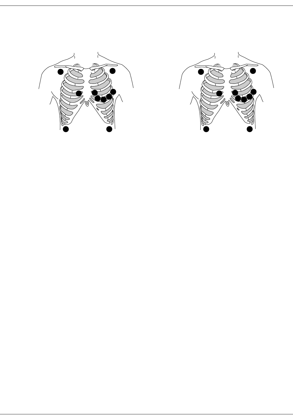
Revision A ApexPro Telemetry System 11-5
2001989-002
ECG Monitoring: Patient Preparation
5-Leadwire (Einthoven + V Lead) and 6-Leadwire Electrode Placement
Following are the standard 5- and 6-leadwire electrode configurations for
AHA and IEC:
Right arm and left arm electrodes should be placed just below the right
and left clavicle.
Right leg and left leg electrodes should be placed on a flat non-muscular
surface on the lower edge of the rib cage.
For standard 5-leadwire electrode placement, the chest electrode should
be placed according to the physician’s preference.
For standard 6-leadwire electrode placement, any two V leads (chest
electrodes) may be placed according to the physician’s preference.
C1
CL
NF
372B
C2
C3 C4C5
C6
V1
RA LA
RL LL
368B
V2
V3 V4 V5
V6
AHA Configuration IEC Configuration
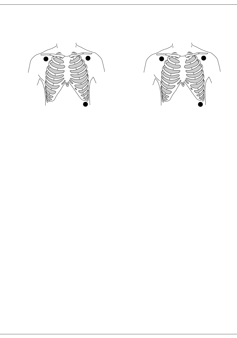
11-6 ApexPro Telemetry System Revision A
2001989-002
ECG Monitoring: Patient Preparation
3-Leadwire Electrode Placement
When a 5-leadwire electrode configuration is not desirable, a 3-leadwire
cable can be used.
127(Electrode configuration will vary depending on the type of
leadwire set you are using.
Right arm and left arm electrodes should be placed just below the right
and left clavicle.
Left leg electrode should be placed on a non-muscular surface on the
lower edge of the rib cage.
Electrode Placement for Pediatric Patients
Typically, pediatric patients are large enough for a 5- or 6-leadwire
electrode configuration. This is the preferred monitoring setup for
receiving the benefits of multi-lead analysis. However, if the patient is
too small for five or six electrodes, the 3-leadwire electrode configuration
can be used. The right arm and left arm electrodes are positioned on the
right and left sides of the chest. The right leg electrode can be placed on
either the right or left side of the abdomen. Refer to the illustrations in
the 3-Leadwire Electrode Placement section above.
RL
F
373A
RA LA
LL
370A
3-Leadwire AHA Configuration 3-Leadwire IEC Configuration
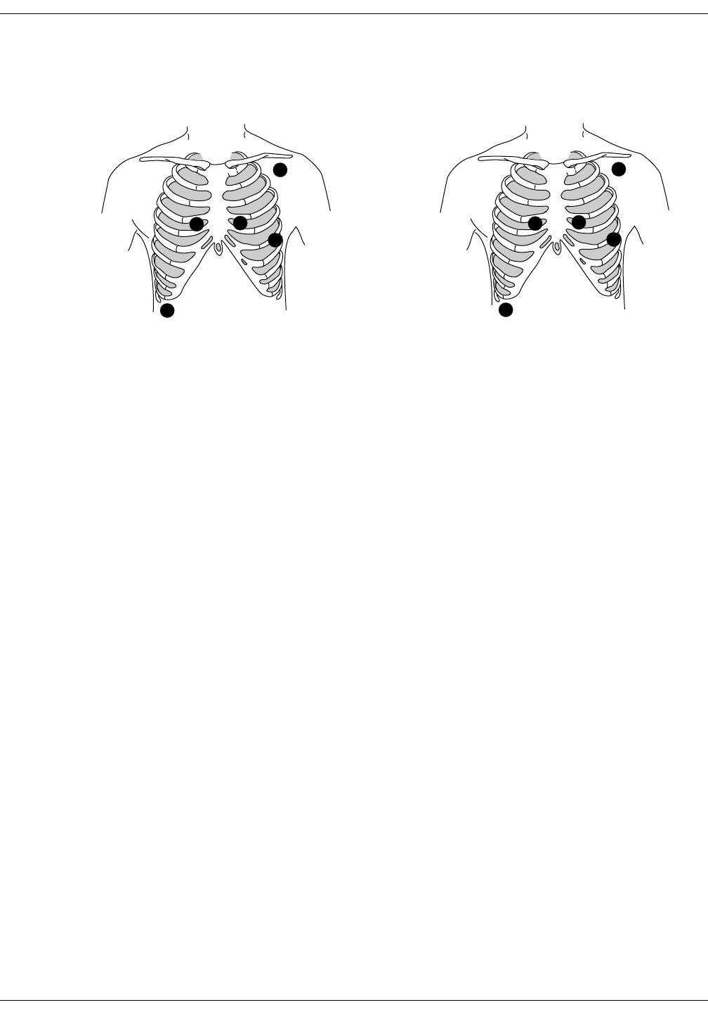
Revision A ApexPro Telemetry System 11-7
2001989-002
ECG Monitoring: Patient Preparation
Modified Chest Lead (MCL) Electrode Placement
Following is the modified chest lead (MCL) electrode configuration with
the associated location:
Right arm electrode should be placed in the fourth intercostal space to
the right of the sternum.
Left arm electrode should be placed just below the left clavicle.
Left leg electrode should be placed in the sixth intercostal space along
the mid-axillary line.
Right leg electrode should be placed on a flat non-muscular surface on
the lower edge of the rib cage.
R
L
C1
F
N
375A
RA
LA
V1
LL
RL
371A
AHA Configuration
MCL Electrode Placement IEC Configuration
MCL Electrode Placement
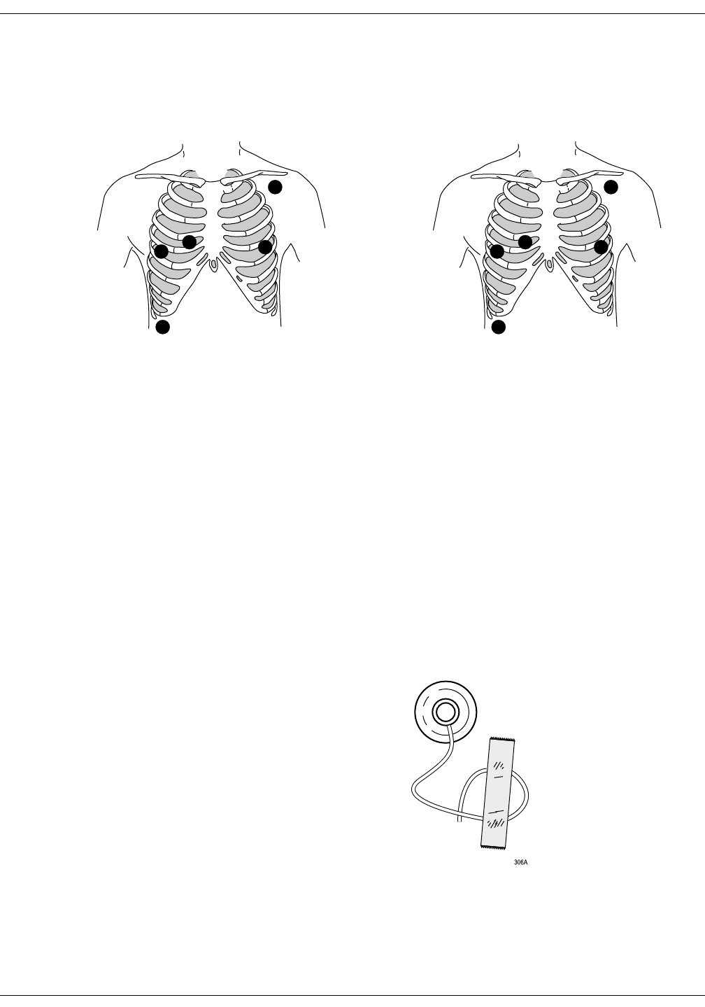
11-8 ApexPro Telemetry System Revision A
2001989-002
ECG Monitoring: Patient Preparation
Electrode Placement for Pacemaker Patients
Electrodes need to be repositioned to modify detection of the electrical
signals generated by the pacemaker. Following is a suggested
configuration:
The right arm electrode is moved down to the fifth intercostal space, and
the left leg electrode is moved up to the fifth intercostal space.
127(After all electrodes are in place, ensure that a minimum of 1/2
mV of signal is present on each lead (I, II, III, V).
Maintaining Quality ECG Signal
Regardless of patient type, electrodes should be replaced at least every
48 hours to maintain quality signals during long-term monitoring. Over
the course of 48 hours, the electrode gel will start to dry out and the
adhesive will age. This may irritate the patient’s skin.
Stabilize the electrode and leadwire with a leadwire stress loop near the
electrode. Tape the stress loop to the patient. A secured stress loop
prevents leadwire rotation about the electrode snap, leadwire tugging at
the electrode, and ECG artifact.
Stress Loop
L
C1
RF
N
374A
RA
LA
V1 LL
RL
369A
AHA Configuration
Pacemaker Electrode Configuration IEC Configuration
Pacemaker Electrode Configuration

Revision A ApexPro Telemetry System 11-9
2001989-002
ECG Monitoring: Special Considerations for 6-Lead Monitoring
Special Considerations for 6-Lead Monitoring
V FAIL
Message
&$87,21
The clinical information center does not detect 6-lead
monitoring until a signal from the sixth lead is received
at the clinical information center. Therefore, if the sixth
lead on the ApexPro transmitter has failed before the
telemetry patient is admitted to the clinical information
center, the clinical information center will not generate a
V FAIL message for the sixth lead.
At the patient’s ApexPro transmitter, verify that the sixth lead on the
ApexPro transmitter is good. Press the Verify Leads button on the
ApexPro transmitter and ensure that all the good lead LEDs illuminate.
(Refer to Chapter 3, Equipment Overview, for button and LED locations.)
Relearn
If a telemetry patient is switched from 6-lead monitoring to 5-lead
monitoring while admitted to the clinical information center, a V FAIL
message will appear. The clinical information center “assumes” that the
telemetry patient is being monitored for six leads and that the sixth lead
has failed.
In situations where the admitted telemetry patient has been switched
from 6- to 5-lead monitoring, the associated V FAIL message can be
cleared by clicking on the Relearn button in the telemetry patient’s ECG
tab sheet. (Refer to the ECG Tab Sheet section in this chapter for
information about the Relearn button.)
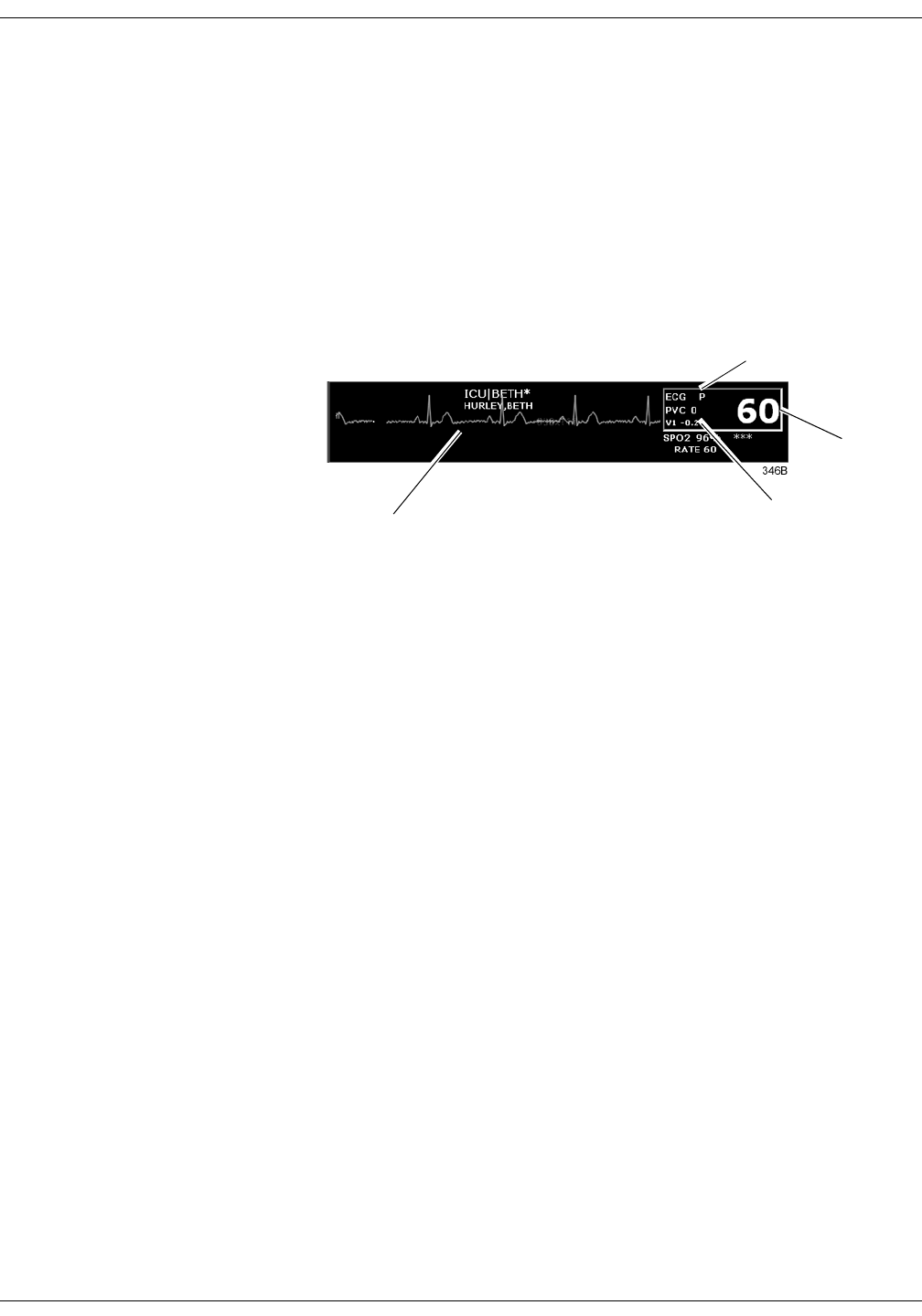
11-10 ApexPro Telemetry System Revision A
2001989-002
ECG Monitoring: ECG Monitoring
ECG Monitoring
ECG in the Multiple Patient Viewer
For telemetry patients, up to four leads of ECG can be displayed in the
bed window of the multiple patient viewer. Also displayed are the
patient’s heart rate, current PVC per minute value, ST analysis, and a
“P” if pace detection is turned on. Below is an example of a telemetry
patient’s bed window in the multiple patient viewer.
Heart rate
Indicates pace
detection is on
ST analysisECG
waveform

Revision A ApexPro Telemetry System 11-11
2001989-002
ECG Monitoring: ECG Monitoring
ECG in the Single Patient Viewer
View Patient Tab Sheet For telemetry patients, up to eight leads of ECG can be seen in the View
Patient tab sheet. It is also possible to sample ten seconds of ECG data
for storage in Alarm Histories, and to initiate a relearn of the patient’s
rhythm. The patient’s heart rate, current PVC per minute value, ST
information, and “P” for pace detection (if turned on) are also displayed.
To access the View Patient tab sheet, follow the steps below.
1. Click in the desired patient’s bed window in the multiple patient
viewer. The display rearranges to accommodate the single patient
viewer for that patient.
2. If it is not already visible at the front of the tabs, click on the View
Patient tab to bring the tab sheet to the front.
For more details about the features and functions of the View Patient tab
sheet, refer to Chapter 7, Admit/View a Patient, in this manual.
Full Disclosure Tab Sheet If full disclosure is turned on, 72 hours of ECG data can be viewed in the
Full Disclosure tab sheet.
To access the Full Disclosure tab sheet, follow the steps below.
1. Click in the desired patient’s bed window in the multiple patient
viewer. The display rearranges to accommodate the single patient
viewer for that patient.
2. Click on the Full Disclosure tab to bring the tab sheet to the front.
For more details about the features and functions of the Full Disclosure
tab sheet, refer to the Clinical Information Center Operator’s Manual.

11-12 ApexPro Telemetry System Revision A
2001989-002
ECG Monitoring: ECG Monitoring
ECG Limits
You can adjust the alarm limits for ECG (such as HR, ST, etc.) in the
Telemetry Alarm Control Defaults tab and in the patient’s Alarm Control
tab. For more information on how to set the alarm limits, refer to
Chapter 8, Alarm Control, in this manual.
ECG Artifact
The clinical information center has two levels for artifact alarms.
Level 1 artifact displays the ARTIFACT message, but continues to
display a heart rate.
The ARTIFACT message does not flash or generate an audible
alarm.
The ARTIFACT message will be relocated to the lead fail area of
the display.
If the patient is in a lead fail, the lead fail message has priority
over the ARTIFACT message on the display.
Level 2 artifact displays the ARTIFACT message, but the heart rate
values are removed from the display.
The ARR SUSPEND message is a system warning alarm.
The clinical information center supports the ARR SUSPEND
message when it is determined that the arrhythmia is in the
level 2 ARTIFACT state.
The ARR SUSPEND message is displayed in the Arrhythmia
event line and is sent to the ADU line for alarm notification at
the level 2 state.
For more information about alarms, refer to Chapter 8, Alarm Control, in
this manual.
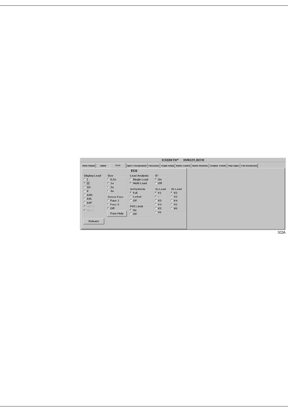
Revision A ApexPro Telemetry System 11-13
2001989-002
ECG Monitoring: ECG Tab Sheet
ECG Tab Sheet
The ECG tab sheet allows you to view and modify settings specific to the
viewed patient’s ECG display. Settings may be viewed for any patient.
However, you can only modify settings for patients who are admitted to a
bed in your care unit.
Accessing the ECG Tab Sheet
To access a patient’s ECG tab sheet in the single patient viewer, follow
this procedure:
1. Click in the desired patient’s bed window in the multiple patient
viewer. The display rearranges to accommodate the single patient
viewer for that patient.
2. Click on the ECG tab in the single patient viewer. The ECG tab sheet
moves to the front.
Display Lead
This option allows you to change the lead currently displayed as the
primary lead. Use the mouse to click on your Display Lead selection.
Relearn
Clicking on the Relearn button initiates a relearn of the patient’s ECG
rhythm. The relearn takes only a few seconds. The patient’s heart rate
reading is momentarily replaced by Xs. Numerics return once the relearn
is complete.
You should use the relearn function whenever there has been a
significant change in the patient’s rhythm.

11-14 ApexPro Telemetry System Revision A
2001989-002
ECG Monitoring: ECG Tab Sheet
Size
This option allows you to change the size of the ECG waveforms
displayed at the clinical information center. This may be necessary when
diagnosing or problem solving. Normal size (1x) is recommended unless
circumstances require otherwise.
To change the waveform display size, use the mouse to click on an option.
127(If a size other than 1x is used, the size is displayed on the left
side of the screen next to the ECG waveform.

Revision A ApexPro Telemetry System 11-15
2001989-002
ECG Monitoring: ECG Tab Sheet
Detect Pace
Safety Considerations Be aware of the following when monitoring a patient with a pacemaker.
:$51,1*6
FALSE CALLS—False low heart rate indicators or false
asystole calls may result with certain pacemakers
because of electrical overshoot.
MONITORING PACEMAKER PATIENTS—Monitoring
of pacemaker patients can only occur with the pace
program activated.
PACEMAKER SPIKE—An artificial pacemaker spike is
displayed in place of the actual pacemaker spike. All
pacemaker spikes appear uniform. Do not diagnostically
interpret pacemaker spike size and shape.
PATIENT HAZARD—A pacemaker pulse can be counted
as a QRS during asystole in either pace mode. Keep
pacemaker patients under close observation.
RATE METERS—Keep pacemaker patients under close
observation. Rate meters may continue to count the
pacemaker rate during cardiac arrest and some
arrhythmias. Therefore, do not rely entirely on rate
meter alarms.
&$87,21
FDA POSTMARKET SAFETY ALERT—The United
States FDA Center for Devices and Radiological Health
issued a safety bulletin October 14, 1998. This bulletin
states “that minute ventilation rate-adaptive
implantable pacemakers can occasionally interact with
certain cardiac monitoring and diagnostic equipment,
causing the pacemakers to pace at their maximum
programmed rate.”
The FDA further recommends precautions to take into
consideration for patients with these types of
pacemakers. These precautions include disabling the rate
responsive mode and enabling an alternate pace mode.
For more information contact:
Office of Surveillance and Biometrics, CDRH, FDA
1350 Piccard Drive, Mail Stop HFZ-510
Rockville, MD 20850
U.S.A.

11-16 ApexPro Telemetry System Revision A
2001989-002
ECG Monitoring: ECG Tab Sheet
127(ECG monitoring with patients on non-invasive transcutaneous
pacemakers may not be possible due to large amounts of energy
produced by these devices. Monitoring ECG with an external
device may be needed.
Monitoring Pacemaker Patients
The Detect Pace option enables/disables the pacemaker detection
program. It must be used whenever the monitored patient has a
pacemaker. Pace detection choices are Pace 1, Pace 2, and Off. Use the
mouse to click on a Detect Pace selection.
There are two pacemaker processing modes, Pace 1 and Pace 2. The Pace
1 and Pace 2 modes use different algorithms for pacemaker artifact
rejection. The clinician must be the judge as to which mode is better for
each patient. The pacemaker detection program defaults off so if you
have a patient with a pacemaker, you will have to turn the program on.
The Pace 2 mode is much more conservative in recognizing paced QRS
morphologies and is recommended for use whenever possible. It is
designed to minimize the possibility of counting pacemaker artifact as
QRS complexes during ASYSTOLE. If the monitor does not adequately
detect paced beats in the Pace 2 mode, then the user may wish to try the
Pace 1 mode. Please observe all cautions as described when
choosing the Pace 1 mode of operation.
The Pace 1 mode allows successful detection of the largest variety of
paced QRS morphologies. As a direct consequence, this mode does have a
higher risk of counting pacemaker artifact as QRS complexes during
ASYSTOLE. For this reason, it is imperative that the user keep patients
with pacemakers under close observation. It is also recommended that
the user set the low heart rate limit on the monitor close to the minimum
pacing rate, and that the BRADY arrhythmia alarm level be elevated to a
WARNING or CRISIS level.
When either pace mode is enabled, the software places an artificial spike
on the waveform whenever the pacemaker triggers. When pacemaker
detection is on, it is indicated by a “P” in the patient’s ECG parameter
window.
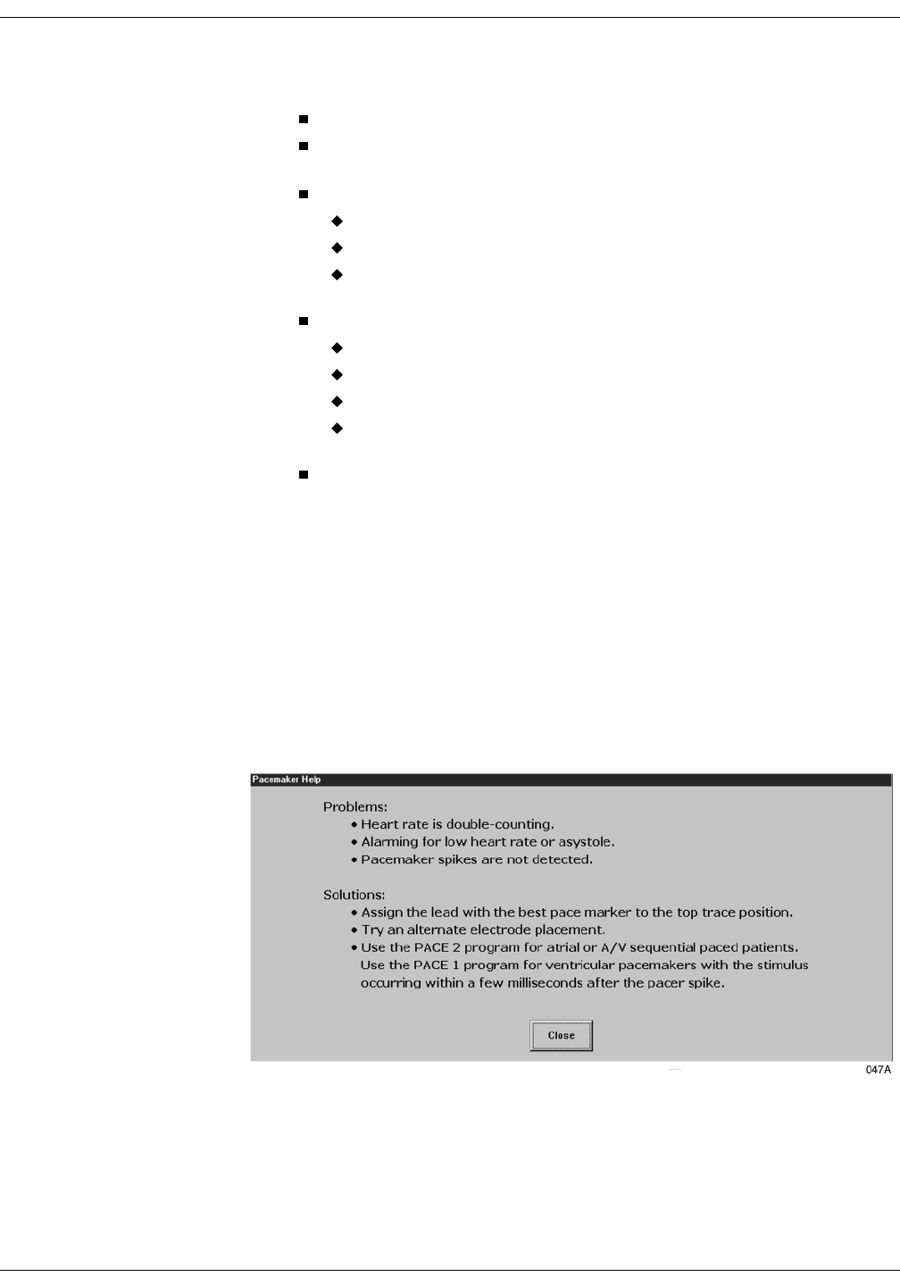
Revision A ApexPro Telemetry System 11-17
2001989-002
ECG Monitoring: ECG Tab Sheet
For successful monitoring of pacemaker patients follow these
suggestions:
Use recommended electrode placement.
Brady, Pause, and Low Heart Rate are additional alarms available
for use when monitoring pacemaker patients.
Problems you may experience are:
heart rate double counting;
inaccurate alarms for low heart rate or asystole;
pacemaker spikes not recognized by the software.
Possible solutions to above problems are:
relearn arrhythmia;
try an alternate electrode placement;
try single-lead analysis;
try switching to the other pace detection mode.
Pacemaker mode:
In most cases, Pace 2 mode will effectively monitor a pacemaker
patient. However, if you are experiencing problems, select the Pace 1
mode as an option, and observe all cautions as described for the
Pace 1 mode of operation.
For more information, refer to the Pacemaker Troubleshooting section in
this chapter.
Pace Help
Clicking on the Pace Help button opens a window that shows common
problems and solutions in regard to pacemaker detection. This window is
shown below.

11-18 ApexPro Telemetry System Revision A
2001989-002
ECG Monitoring: ECG Tab Sheet
Lead Analysis
The Lead Analysis control signals the ApexPro transmitter to process the
ECG in Single Lead or Multi-Lead mode. Use the mouse to click on your
selection. Multi-lead analysis is the default setting for adults.
Multi-Lead Analysis
Multi-lead analysis simultaneously examines ECG leads I, II, III, and V
(whether they are displayed or not) to help eliminate false alarms and
improve the ability of the system to:
Detect beats which occur isoelectric to a single chest lead.
Discriminate artifact that appears in one lead compared to the other
lead vectors.
Provide a “smart-lead fail” feature, where the failed lead is identified,
and if available, another lead is provided for display.
Continue arrhythmia processing even after a lead change.
Single Lead Analysis
Single lead analysis uses only the lead displayed on the clinical
information center screen to process ECG and arrhythmia information.
To change the lead used for single lead analysis, you must change the
displayed lead.
Single lead analysis is beneficial when troubleshooting pacemaker
detection and/or arrhythmia detection. Single lead analysis must always
be used when monitoring with a 3-lead cable. Single lead analysis can be
set up as a unit default. Refer to Chapter 6, Telemetry Setup, for more
information.

Revision A ApexPro Telemetry System 11-19
2001989-002
ECG Monitoring: ECG Tab Sheet
Arrhythmia
127(Full arrhythmia
processing is suspended when the
level 1 “ARTIFACT” message is
displayed. Lethal arrhythmia is
still active but its accuracy may be
hindered by the artifact.
:$51,1*6
SUSPENDED ANALYSIS—Certain conditions suspend
arrhythmia analysis. When suspended, arrhythmia
conditions are not detected and alarms associated with
arrhythmias do not occur. The messages which alert you
to the conditions causing suspended arrhythmia analysis
are: ALL ALARMS OFF, ALARM PAUSE, ARR OFF,
ARR SUSPEND, DISCHARGED, LEADS FAIL, and NO
TELEM. Additionally, the alarms off with reason options
and disabling the alarm pause breakthrough feature also
suspend arrhythmia analysis.
VENTRICULAR ARRHYTHMIAS—The arrhythmia
analysis program is intended to detect ventricular
arrhythmias. It is not designed to detect atrial or
supraventricular arrhythmias. Occasionally it may
incorrectly identify the presence or absence of an
arrhythmia. Therefore, a physician must analyze the
arrhythmia information in conjunction with other clinical
findings.
The arrhythmia control signals the clinical information center to ignore
or accept arrhythmia calls. To modify arrhythmia settings, use the
mouse to click on Full, Lethal, or Off.
127(When arrhythmia program is in Full mode, the program counts
the number of PVCs that occur within a minute.
Turning arrhythmia on automatically starts a relearn procedure.
When arrhythmia is turned off, ARR OFF appears in the ECG
parameter window.

11-20 ApexPro Telemetry System Revision A
2001989-002
ECG Monitoring: ECG Tab Sheet
Full Arrhythmia Conditions
Below is an alphabetical list of the arrhythmia messages that are
displayed when full arrhythmia is selected and the condition occurs.
Definitions of each condition are included. The CIC’s response to each
condition is determined by the alarm level to which the arrhythmia has
been assigned.
ACC VENT Adult—Accelerated ventricular occurs when six or more
ventricular beats are detected with an average heart rate for
the ventricular beat between 50 and 100 beats per minute.
0-2 years—Occurs when six or more ventricular beats are
detected with an average heart rate for the ventricular beat
between 60 and 160 beats per minute.
3-10 years—Occurs when six or more ventricular beats are
detected with an average heart rate for the ventricular beat
between 60 and 140 beats per minute.
11-13 years—Occurs when six or more ventricular beats are
detected with an average heart rate for the ventricular beat
between 60 and 130 beats per minute.
ASYSTOLE Ventricular asystole occurs whenever the displayed heart rate
drops to zero.
BIGEMINY Occurs when three or more bigeminal cycles (a ventricular
beat followed by a non-ventricular beat) are detected.
BRADY Bradycardia is the average of the most recent eight R-to-R
intervals at a heart rate less than the set low heart rate limit.
127(The Brady limit matches the low heart
rate limit. If the low heart rate limit is
changed, the Brady limit changes.
COUPLET Occurs when two ventricular beats are detected and have non-
ventricular beats before and after the couplet. The coupling
interval must be less than 600 milliseconds.
IRREGULAR Occurs when six consecutive normal R-to-R intervals vary by
100 milliseconds or more.
PAUSE Occurs when a 3-second interval without a QRS complex is
detected.
PVC Isolated premature ventricular complexes occur when a
premature ventricular beat is detected and has non-ventricular
beats before and after.
R ON T Occurs when a ventricular complex is detected within the
repolarization period of a non-ventricular beat.

Revision A ApexPro Telemetry System 11-21
2001989-002
ECG Monitoring: ECG Tab Sheet
:$51,1*
VFIB/VTAC should not be considered a substitute for
the V TACH arrhythmia call. Efforts to lower the V
TACH alarm level can result in missed ventricular
tachycardia alarms.
TACHY Tachycardia is four R-to-R intervals at a heart rate greater than
the set high heart rate limit.
127(The Tachy limit matches the high heart
rate limit. If the high heart rate limit is
changed, the Tachy limit changes.
TRIGEMINY Occurs when three or more trigeminal cycles (a ventricular
beat followed by two non-ventricular beats) are detected.
V BRADY Adult—Ventricular bradycardia occurs when a run of three or
more ventricular beats is detected with an average heart rate
that is less than or equal to 50 beats per minute.
0-2, 3-10, and 11-13 years—Occurs when a run of three or
more ventricular beats is detected with an average heart rate
that is less than or equal to 60 beats per minute.
VFIB/ VTAC Ventricular fibrillation occurs when the ECG waveform
indicates a chaotic ventricular rhythm.
V TACH Adult—Ventricular tachycardia occurs when a run of six or
more ventricular beats is detected with an average heart rate
greater than or equal to 100 beats per minute.
0-2 years—Occurs when a run of six or more ventricular beats
is detected with an average heart rate greater than or equal to
160 beats per minute.
3-10 years—Occurs when a run of six or more ventricular
beats is detected with an average heart rate greater than or
equal to 140 beats per minute.
11-13 years—Occurs when a run of six or more ventricular
beats is detected with an average heart rate greater than or
equal to 130 beats per minute.

11-22 ApexPro Telemetry System Revision A
2001989-002
ECG Monitoring: ECG Tab Sheet
Lethal Arrhythmia Conditions
When Lethal arrhythmia is selected, the following conditions (as defined
for Full arrhythmia) are detected:
ASYSTOLE
VFIB/VTAC
V TACH (defaults to the Crisis level, but can be moved to a different
level)
BRADY (if the patient age range selected is 0-2 years or 3-10 years)
PVC Limit
When on, the PVC Limit control displays a PVC counter in the ECG
parameter window. When off, the PVC counter is not displayed. Use the
mouse to turn the PVC Limit control On or Off.
The PVC limits are preset in Alarm Control defaults. For more
information on setting the limits, refer to Chapter 8, Alarm Control, in
this manual.
ST
The ST control turns the display of ST segment analysis data on and off.
Use the mouse to turn ST segment analysis On or Off. For more
information about ST analysis, refer to the ST Analysis section in this
chapter.
VT > 2 Adult—Ventricular tachycardia >2 occurs when a run of
ventricular beats is detected with a duration of less than six
beats but longer than two beats and with an average heart rate
that is greater than or equal to 100 beats per minute.
0-2 years—Occurs when a run of ventricular beats is detected
with a duration of less than six beats but longer than two beats
and with an average heart rate that is greater than or equal to
160 beats per minute.
3-10 years—Occurs when a run of ventricular beats is
detected with a duration of less than six beats but longer than
two beats and with an average heart rate that is greater than or
equal to 140 beats per minute.
11-13 years—Occurs when a run of ventricular beats is
detected with a duration of less than six beats but longer than
two beats and with an average heart rate that is greater than or
equal to 130 beats per minute.

Revision A ApexPro Telemetry System 11-23
2001989-002
ECG Monitoring: ECG Tab Sheet
Va Lead and Vb Lead
These two option lists allows you to label the V leads. Use the mouse to
click on your Va Lead and Vb Lead selections.
127(Vb Lead selections are only available with 6-lead monitoring.

11-24 ApexPro Telemetry System Revision A
2001989-002
ECG Monitoring: ST Analysis
ST Analysis
The patient’s most dominant, normal beat is used for ST measurement.
This beat is identified by the arrhythmia analysis program. Turn ST on
to display the numerics calculated for ST at the clinical information
center.
GE Marquette identifies the ST segment of the QRS complex as
beginning at the J point and ending 60 milliseconds following the J point.
The ST numeric displayed (millimeters) indicates either a positive or
negative elevation in relation to the isoelectric reference point (which is
also determined by the arrhythmia program and the patient’s age).
When ST is on, numerics are displayed under each ECG lead label on the
screen. (A negative deflection is preceded by a minus sign.) These
numerics are updated about every 15 seconds.
The ST value shown in the ECG parameter window is the lead with the
greatest ST deviation. This may or may not be the lead that is in alarm,
since a lead with a lesser deviation from the isoelectric line may have
changed more than the lead with the greatest deviation.
127(ST numerics are always calculated with reference to 1X size.
Displaying the ECG waveform at a different size does not affect
the ST values.
127(When a new dominant beat is detected or a relearn occurs, the
arrhythmia program calculates ST based on the new beat. This
could affect the ST values displayed. This may not necessarily
represent a change in the patient’s condition. The clinician needs
to assess the patient any time there is an ST change.
ST Deviation Alarm
When any individual ST value is beyond the limit, an ST deviation alarm
occurs. It is considered a parameter alarm, and the default alarm level is
warning. This can be modified in the parameter alarm level setup.
127(ST is not stored in alarm history since it is treated as a
parameter alarm.
When the ST program is turned on, or a relearn is done with ST on,
the ST deviation values are set for all leads of ST.
+/- 2 mm absolute limits are automatically set around the ST value
during a Relearn.
The current ST value is determined in all eight leads.
The ST value in the ECG parameter window flashes to indicate an
alarm.
To reset the limits for ST after an alarm violation, select Relearn.
ST limits can also be adjusted individually in the patient’s Alarm
Control tab.

Revision A ApexPro Telemetry System 11-25
2001989-002
ECG Monitoring: Arrhythmia Troubleshooting
Arrhythmia Troubleshooting
Problem: Inaccurate heart rate
and/or false asystole Solution: Check ECG signal from patient:
1. Check/adjust lead placement.
2. Check/perform skin preparation.
3. Check/replace electrodes.
Check amplitude of ECG waveform:
1. Click on the patient’s ECG tab.
2. Click on all ECG leads in the Display section and check for 0.5 mV
amplitude at normal (1X) size. (At least 0.5 mV amplitude is required
for QRS detection.) For borderline signals, validate on a graph.
3. If amplitudes are low, electrodes may need to be repositioned or
replaced.
Relearn arrhythmia:
1. Click on the patient’s ECG tab.
2. Click on the Relearn button.
IF PROBLEM CONTINUES: Change to single lead ECG detection and
processing:
1. Click on the patient’s ECG tab.
2. Click on Single Lead in the Lead Analysis section.
3. Click on the ECG leads in the Display section and change top ECG
waveform to display the lead with the greatest amplitude. (At least
0.5 mV amplitude is required for QRS detection.)
Problem: False ventricular calls Solution: Check ECG signal from patient: (V leads may exhibit polarity
changes which may occasionally cause an inaccurate call.)
1. Check/adjust lead placement.
2. Check/perform skin preparation.
3. Check/replace electrodes. (If V lead is a problem, move the V lead to
another V position.)
4. Relearn ECG:
a. Click on the patient’s ECG tab.
b. Click on the Relearn button.
IF PROBLEM CONTINUES:
1. Remove the V lead(s).
2. Click on the patient’s ECG tab.
3. Click on the Relearn button.

11-26 ApexPro Telemetry System Revision A
2001989-002
ECG Monitoring: Pacemaker Troubleshooting
Pacemaker Troubleshooting
There are two general things that occur when the pace mode is activated
for pacemaker patients:
1. Beats that would otherwise be classified as ventricular are instead
classified as V-paced if a ventricular pacemaker event is detected.
2. Residual pacemaker energy that might otherwise appear in the ECG
is removed, and a “pacemaker enhancement spike” (shown in an
offset color from the ECG waveform) is artificially placed in the ECG.
Pace detection is indicated visually in the ECG parameter box. When
watching the ECG waveform, pace detection is indicated by uniform,
upright pacemaker enhancement spikes in the ECG data (both displayed
and graphed).
During telemetry monitoring, the pacemaker signal is acquired from lead
II. Changing the displayed lead has no effect on pacemaker detection.
127(With all leads connected, pacemaker signal acquisition occurs on
lead II. In a lead fail condition, signal acquisition occurs on any
available lead. Single channel acquisition occurs on the
programmed lead.
To improve pacemaker detection, reposition the electrodes and assure a
good skin preparation to maximize R-wave detection.

Revision A ApexPro Telemetry System 11-27
2001989-002
ECG Monitoring: Pacemaker Troubleshooting
Problem: Inaccurate pacemaker
detection Solution: Use pacemaker processing:
1. Click on the patient’s ECG tab.
2. In the Detect Pace section, select either Pace 1 or Pace 2.
Notes:
In general, be aware that a pacemaker pulse could be falsely
counted as a QRS during asystole.
Pace 1 mode analyzes the presence of a pacer spike, assesses the
waveform for residual pacemaker energy, and determines the
presence of an R wave following the pacer spike. If an event occurs
during the first few milliseconds following the pacer spike, it will be
counted.
Pace 2 mode analyzes waveforms with the added capability of
minimizing the chance of counting severe residual pacemaker energy
as QRS complexes. In relation to the event rejection capability of
Pace 2 pace mode, certain morphologies may not be detected.
Arrhythmia calls like asystole or pause may be made with heart rate
identified as less than actual.
Again, pacemaker patients should be kept under close observation.
The appropriate pace mode may be determined at the time the
pacemaker patient is admitted to the monitoring system. The Pace 2
mode is recommended for use whenever possible.
Check ECG signal from patient:
1. Check/adjust lead placement.
2. Check/perform skin preparation.
3. Check/replace electrodes.

11-28 ApexPro Telemetry System Revision A
2001989-002
ECG Monitoring: ST Troubleshooting
ST Troubleshooting
Problem: ST numerics changed to
Xs Solution: An ST value changes to Xs when the patient’s dominant
morphology has not been detected 16 times in the last 30 seconds. The
program waits one minute and then automatically relearns. ST numerics
will be displayed after the relearn.
IF PROBLEM CONTINUES:
1. Check for morphology change.
2. Check for noise on ECG.
3. Relearn:
a. Click on the patient’s ECG tab.
b. Click on the Relearn button.

Revision A ApexPro Telemetry System 12-1
2001989-002
12 SpO2 Monitoring
Introduction . . . . . . . . . . . . . . . . . . . . . . . . . . . . . . . . . . . . . . . . . . . . . . . . . . . . . . . 12-3
SpO2 Probe Safety . . . . . . . . . . . . . . . . . . . . . . . . . . . . . . . . . . . . . . . . . . . . . . .12-3
Infants and Pulse Oximetry . . . . . . . . . . . . . . . . . . . . . . . . . . . . . . . . . . . . . . . . . . 12-4
Signal and Data Validity . . . . . . . . . . . . . . . . . . . . . . . . . . . . . . . . . . . . . . . . . . . . . 12-5
Signal Strength Indicator . . . . . . . . . . . . . . . . . . . . . . . . . . . . . . . . . . . . . . . . . . .12-5
Error Messages . . . . . . . . . . . . . . . . . . . . . . . . . . . . . . . . . . . . . . . . . . . . . . . . . .12-5
SPO2 Monitoring . . . . . . . . . . . . . . . . . . . . . . . . . . . . . . . . . . . . . . . . . . . . . . . . . . . 12-6
SPO2 in the Multiple Patient Viewer . . . . . . . . . . . . . . . . . . . . . . . . . . . . . . . . . .12-6
SPO2 in the Single Patient Viewer . . . . . . . . . . . . . . . . . . . . . . . . . . . . . . . . . . .12-6
SPO2 Limits . . . . . . . . . . . . . . . . . . . . . . . . . . . . . . . . . . . . . . . . . . . . . . . . . . . . 12-7
SPO2 Tab Sheet . . . . . . . . . . . . . . . . . . . . . . . . . . . . . . . . . . . . . . . . . . . . . . . . . . . . 12-8
Accessing the SPO2 Tab Sheet . . . . . . . . . . . . . . . . . . . . . . . . . . . . . . . . . . . . .12-8
Rate . . . . . . . . . . . . . . . . . . . . . . . . . . . . . . . . . . . . . . . . . . . . . . . . . . . . . . . . . . .12-8
Size . . . . . . . . . . . . . . . . . . . . . . . . . . . . . . . . . . . . . . . . . . . . . . . . . . . . . . . . . . .12-8
Troubleshooting . . . . . . . . . . . . . . . . . . . . . . . . . . . . . . . . . . . . . . . . . . . . . . . . . . . 12-9
SpO2 Messages . . . . . . . . . . . . . . . . . . . . . . . . . . . . . . . . . . . . . . . . . . . . . . . . .12-9


Revision A ApexPro Telemetry System 12-3
2001989-002
SpO2 Monitoring: Introduction
Introduction
127(SpO2 and SPO2 are used interchangeably throughout this
manual to refer to pulse oximetry.
The Apex Oximeter functions as a stand-alone device, and displays
digital values for SpO2 and pulse rate. When the Apex Oximeter is
connected to the ApexPro transmitter, digital values for SpO2 and pulse
rate are also displayed at the clinical information center.
127(When monitoring SpO2 via telemetry, an SpO2 waveform is
neither generated nor displayed on the Apex Oximeter or clinical
information center. Additionally, no alarm histories are
generated or stored.
SpO2 Probe Safety
Be sure to read all literature accompanying probes for specific safety
information. Be aware of the following safety precautions when using
SpO2 probes.
:$51,1*6
DATA VALIDITY—Do not expose probe detector to
strong ambient light while monitoring a patient. A poor
signal may result.
DATA VALIDITY—Do not allow tape to block the probe
light detector.
PATIENT SAFETY—Prolonged monitoring may require
changing the probe site periodically. Move the probe if
there is any sign of skin irritation or impaired
circulation. Change the probe site at least every four hours
to prevent ischemic skin necrosis. If required, reduce the
application periods to half the times recommended above.
PATIENT SAFETY—If a probe is damaged in any way,
discontinue use immediately.
&$87,21
Use only Nonin SpO2 probes with the Apex Oximeter.
The reliability of SpO2 data obtained with any other
probe has not been verified.

12-4 ApexPro Telemetry System Revision A
2001989-002
SpO2 Monitoring: Infants and Pulse Oximetry
Infants and Pulse Oximetry
:$51,1*
The display of inaccurate pulse oximetry (SPO2) values
has been linked to the presence of poor signal strength or
artifact due to patient motion during signal analysis.
This condition is most likely to be encountered when the
equipment is used on infants. These same conditions in
adults do not impact the SPO2 values to the same extent.
When using pulse oximetry on infants, always observe the
following precautions.
Precautions
We recommend the application of the following criteria when using the
pulse oximetry function on infants:
1. The peripheral pulse rate (PPR) as determined by the SPO2 function
must be within 10% of the heart rate, and
2. the SPO2 signal strength indicator must have 2 or 3 asterisks
displayed, and
3. stable SPO2 values are displayed for six seconds.
Procedures or devices previously applied in your facility for SPO2
monitoring should be used in the event that the SPO2 value from the
equipment cannot be validated by the above criteria.
&$87,21
Do not use the Apex Oximeter on neonatal patients. It is
not designed for use on neonates.

Revision A ApexPro Telemetry System 12-5
2001989-002
SpO2 Monitoring: Signal and Data Validity
Signal and Data Validity
It is extremely important to determine that the probe is attached to the
patient correctly and the data is verifiable. To make this determination,
the signal strength indicators on the Apex Oximeter and the clinical
information center are of assistance.
Signal Strength Indicator
A signal strength (perfusion) indicator is displayed on the Apex Oximeter
display and at the clinical information center in the appropriate patient
window.
On the Apex Oximeter, this indicator is a perfusion LED that blinks with
each SpO2 pulse detected. The LED blinks green for each acceptable
strength pulse. It blinks yellow for SpO2 signals of marginal quality, and
blinks red when the SpO2 signal is too weak or the quality is very poor.
When the perfusion LED blinks red, the numeric data displayed on the
Apex Oximeter will be replaced by dashes within 10 seconds.
At the clinical information center, the signal strength indicator consists
of 0, 1, 2, or 3 (strongest) asterisks, depending on the strength of the
signal.
Proper environmental conditions and probe attachment help ensure a
strong signal.
:$51,1*
In the monitoring of patients the coincidence of adverse
conditions may lead to a disturbed signal going
unnoticed. In this situation artifacts are capable of
simulating a plausible parameter reading, so that the
monitor fails to sound an alarm. In order to ensure
reliable patient monitoring, the proper application of the
probe and the signal quality must be checked at regular
intervals.
Error Messages
If the probe is not correctly attached to the patient and data is not
verifiable, one of the following error messages may appear in the
patient’s bed window at the clinical information center:
SPO2 PROBE OFF
SPO2 PROBE
If either of the above messages appears, check the position of the probe or
replace the probe. If the problem persists, call GE Marquette Service or
contact your sales/service representative.
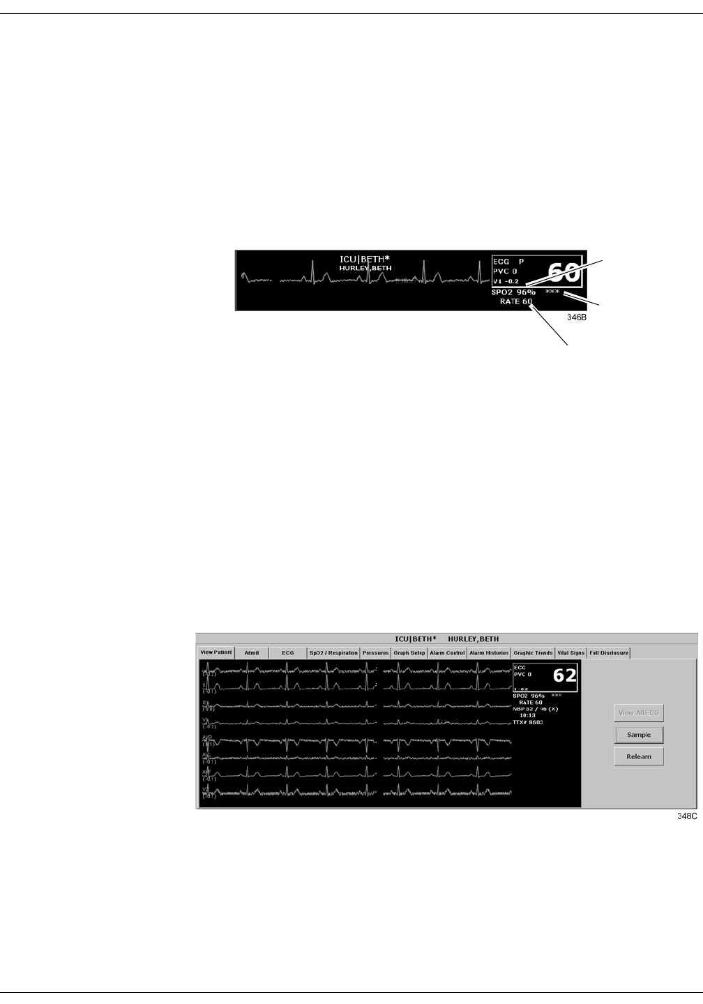
12-6 ApexPro Telemetry System Revision A
2001989-002
SpO2 Monitoring: SPO2 Monitoring
SPO2 Monitoring
SPO2 in the Multiple Patient Viewer
In the multiple patient viewer, the bed window for a telemetry patient
being monitored for SpO2 displays the current SPO2 value; one, two, or
three asterisks indicating signal strength; and, if turned on, the derived
pulse rate for the patient. Below is an example of a telemetry patient’s
bed window in the multiple patient viewer.
SPO2 in the Single Patient Viewer
In the single patient viewer, SpO2 data appears in the View Patient tab
sheet in the same format and location as it does in the multiple patient
viewer.
To access the View Patient tab sheet, follow the steps below.
1. Click in the desired patient’s bed window in the multiple patient
viewer. The display rearranges to accommodate the single patient
viewer for that patient.
2. If it is not already visible at the front of the tabs, click on the View
Patient tab to bring the tab sheet to the front.
For more information about the View Patient tab sheet, refer to Chapter
7, Admit/View a Patient, in this manual.
Signal Strength
Indicator
SPO2 Value
Pulse Rate Value

Revision A ApexPro Telemetry System 12-7
2001989-002
SpO2 Monitoring: SPO2 Monitoring
SPO2 Limits
You can adjust alarm limits for SPO2 and rate in the Alarm Control tab
sheet for each patient. SPO2 alarm limits cannot be set as unit defaults.
For more information on how to set the alarm limits, refer to Chapter 8,
Alarm Control, in this manual.
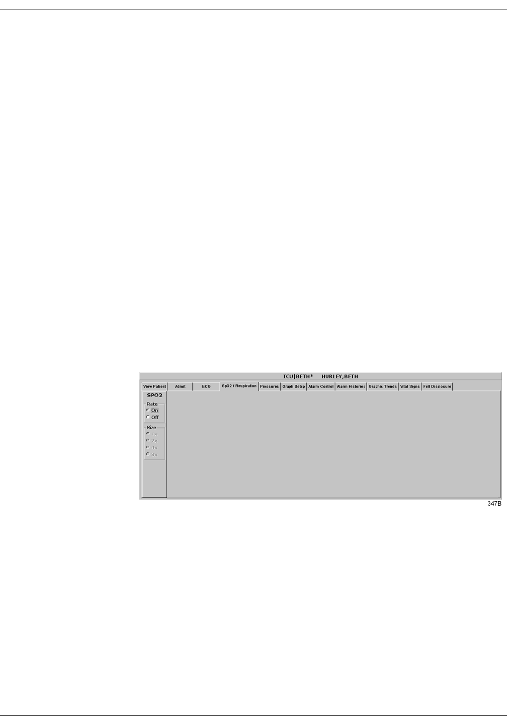
12-8 ApexPro Telemetry System Revision A
2001989-002
SpO2 Monitoring: SPO2 Tab Sheet
SPO2 Tab Sheet
The SpO2/Respiration tab sheet allows you to view and modify settings
specific to the viewed patient’s SpO2 display. Settings may be viewed for
any patient. However, you can only modify settings for patients who are
admitted to a bed in your unit.
127(The SPO2 tab is labeled SpO2/Respiration because respiration
monitoring settings are available on this tab sheet for bedside
monitored patients only.
Respiration monitoring is not an option for telemetry patients.
Therefore only SpO2 information appears on this tab sheet when
monitoring a telemetry patient.
Accessing the SPO2 Tab Sheet
To access a patient’s SpO2 tab sheet in the single patient viewer, follow
this procedure.
1. Click in the desired patient’s bed window in the multiple patient
viewer. The display rearranges to accommodate the single patient
viewer for that patient.
2. Click on the SpO2/Respiration tab in the single patient viewer. The
SpO2 tab sheet moves to the front.
Rate
A pulse rate is derived from the SPO2 signal and is displayed in the
parameter window. You can turn this displayed rate off and on. Simply
click On to turn rate on, or Off to turn rate off.
Size
Because no waveform is displayed when SpO2 is monitored via
telemetry, the Size option does not function for telemetry patients. Size
and its selections appear dimmed when monitoring telemetry patients.

Revision A ApexPro Telemetry System 12-9
2001989-002
SpO2 Monitoring: Troubleshooting
Troubleshooting
SpO2 Messages
Below is a list of system status alarm messages that may be displayed in
the patient’s bed window during monitoring. SpO2 messages appear in
abbreviated form in graph headers. If you are unable to resume SpO2
monitoring, contact your sales/service representative.
CHANGE BATTERY
Message displayed with SPO2 data displayed—The batteries in the Apex
Oximeter are low. There is approximately 1 hour of reserve power left in
the batteries. Change the batteries. Refer to Chapter 4, Connection, for
information about changing batteries.
Message displayed, no SPO2 data displayed—The batteries in the Apex
Oximeter are depleted. Replace the batteries. Refer to Chapter 4,
Connection, for information about changing batteries. This is a system
advisory alarm. The alarm will sound, and a red alarm button will
appear on the clinical information center display. If the batteries are not
replaced within 20 minutes, all SPO2 parameter information will be
removed from the display. If the batteries are replaced within 20
minutes, SpO2 monitoring will resume.
SPO2 PROBE
The probe has been disconnected from the Apex Oximeter (no data is
displayed).
SIGNAL
SpO2 data continues to be displayed, but the quality of the signal is
questionable. Check the patient and the probe.
NO DATA
The Apex Oximeter is still connected, but no valid data is being
transmitted to the receiver. Check that the patient is within antenna
range. If the problem persists, contact GE Marquette Service.
SPO2 PROBE OFF
The probe is off the patient. Check the probe.
The saturation value is X
The Apex Oximeter is still connected, but no valid data is being received
at the receiver. The patient may be in an area of poor antenna reception,
where some, but not all data is being transmitted.
This message remains on the clinical information center for three
minutes. If no data is detected after three minutes, the message changes
to NO DATA.

12-10 ApexPro Telemetry System Revision A
2001989-002
SpO2 Monitoring: Troubleshooting
For your notes

Revision A ApexPro Telemetry System 13-1
2001989-002
13 NBP Monitoring
Introduction . . . . . . . . . . . . . . . . . . . . . . . . . . . . . . . . . . . . . . . . . . . . . . . . . . . . . . . 13-3
Safety Considerations . . . . . . . . . . . . . . . . . . . . . . . . . . . . . . . . . . . . . . . . . . . . . . . 13-4
Programming the Blood Pressure Monitor . . . . . . . . . . . . . . . . . . . . . . . . . . . . . . 13-5
Setting the Measurement Interval . . . . . . . . . . . . . . . . . . . . . . . . . . . . . . . . . . . .13-5
Setting Test Parameters . . . . . . . . . . . . . . . . . . . . . . . . . . . . . . . . . . . . . . . . . . .13-6
Setting Limits . . . . . . . . . . . . . . . . . . . . . . . . . . . . . . . . . . . . . . . . . . . . . . . . . . . .13-7
Software and Hardware Versions . . . . . . . . . . . . . . . . . . . . . . . . . . . . . . . . . . . .13-7
Patient Preparation . . . . . . . . . . . . . . . . . . . . . . . . . . . . . . . . . . . . . . . . . . . . . . . . . 13-8
Microphone Placement . . . . . . . . . . . . . . . . . . . . . . . . . . . . . . . . . . . . . . . . . . . .13-9
Placement in the Microphone Pad . . . . . . . . . . . . . . . . . . . . . . . . . . . . . . . .13-9
Placement in the Blood Pressure Cuff . . . . . . . . . . . . . . . . . . . . . . . . . . . .13-10
NBP Monitoring . . . . . . . . . . . . . . . . . . . . . . . . . . . . . . . . . . . . . . . . . . . . . . . . . . . 13-11
NBP in the Multiple Patient Viewer . . . . . . . . . . . . . . . . . . . . . . . . . . . . . . . . . .13-11
NBP in the Single Patient Viewer . . . . . . . . . . . . . . . . . . . . . . . . . . . . . . . . . . . .13-11
NBP Limits . . . . . . . . . . . . . . . . . . . . . . . . . . . . . . . . . . . . . . . . . . . . . . . . . . . . .13-11
Pressures Tab Sheet . . . . . . . . . . . . . . . . . . . . . . . . . . . . . . . . . . . . . . . . . . . . . . . 13-12
Accessing the Pressures Tab Sheet . . . . . . . . . . . . . . . . . . . . . . . . . . . . . . . . .13-12
Auto . . . . . . . . . . . . . . . . . . . . . . . . . . . . . . . . . . . . . . . . . . . . . . . . . . . . . . . . . 13-13
Cuff Size . . . . . . . . . . . . . . . . . . . . . . . . . . . . . . . . . . . . . . . . . . . . . . . . . . . . . .13-13
Clear Message . . . . . . . . . . . . . . . . . . . . . . . . . . . . . . . . . . . . . . . . . . . . . . . . . .13-13
Troubleshooting . . . . . . . . . . . . . . . . . . . . . . . . . . . . . . . . . . . . . . . . . . . . . . . . . . 13-14
NBP Status Messages . . . . . . . . . . . . . . . . . . . . . . . . . . . . . . . . . . . . . . . . . . . .13-14


Revision A ApexPro Telemetry System 13-3
2001989-002
NBP Monitoring: Introduction
Introduction
127(The Accutracker DX noninvasive blood pressure monitor is
available in the United States only. This model, available from
GE Marquette, has been modified by SunTech Medical
Instruments to operate with the ApexPro telemetry system.
NBP monitoring via telemetry is done with an Accutracker DX
noninvasive blood pressure monitor connected to the ApexPro
transmitter. The blood pressure cuff is connected to the Accutracker DX
blood pressure monitor, which measures and displays systolic and
diastolic blood pressures using the auscultatory method. When the blood
pressure monitor is connected to an ApexPro transmitter, digital values
are also displayed at the clinical information center.
:$51,1*
The following conditions may affect the accuracy of
noninvasive blood pressure readings: seizures, tremors,
extreme hypotension or hypertension, arrhythmias, or
extremely high or low heart rate.

13-4 ApexPro Telemetry System Revision A
2001989-002
NBP Monitoring: Safety Considerations
Safety Considerations
Keep the following warnings and cautions in mind when using the
Accutracker DX noninvasive blood pressure monitor.
:$51,1*6
The Accutracker DX noninvasive blood pressure monitor
is designed for use with adult patients only. Do not use
on neonates or on patients known to be susceptible to
bruising.
Do not attach the blood pressure cuff to a limb being
used for IV infusions as the cuff inflation can block the
infusion, causing harm to the patient.
&$87,216
The blood pressure monitor’s safety and effectiveness in
neonates has not been established.
Blood pressure measurements may be affected by the
patient’s position, physical condition, and other factors.
Do not use the blood pressure monitor if it has failed its
diagnostic self test or if it displays a pressure greater
than zero with no cuff attached. The values displayed by
such a unit may be inaccurate.
If you must ship the Accutracker DX noninvasive blood
pressure monitor for service or other reasons, place it in a
sealable plastic bag, seal it tightly, then package it in a
cardboard box. Label the shipping container “–20 to +50
Deg. C” and ship appropriately. Failure to follow these
instructions can result in device failure due to improper
shipping/storage conditions.

Revision A ApexPro Telemetry System 13-5
2001989-002
NBP Monitoring: Programming the Blood Pressure Monitor
Programming the Blood Pressure Monitor
The blood pressure measurement interval, the maximum and minimum
inflation pressures, dynamic or fixed inflate, and the deflate rate can all
be adjusted on the Accutracker DX blood pressure monitor. Follow the
instructions below to set these options.
Setting the Measurement Interval
When the blood pressure monitor is turned on, it performs a battery
voltage check, then the display shows the following:
INT= 5 (***)
INCR DECR START?
127(The number 5 above represents any measurement interval,
including MAN (manual). When the blood pressure monitor is
turned on, the number displayed is the last measurement
interval set as the default.
Use the YES + button or the NO – button on the blood pressure monitor
to increase or decrease the interval (INT) at which the blood pressure
readings are taken.
The available measurement intervals are: MAN (manual), or 5, 6, 7, 8, 9,
10, 15, 20, 25, 30, 35, 40, 45, 50, 55, 60, 90, 120, or 240 minute intervals.
When the desired measurement interval is reached, press the START/
STOP button. The blood pressure monitor immediately begins a
measurement cycle. It will attempt one retry if the first measurement
cycle fails.
Measurements are taken at the selected interval. A measurement may
be initiated in between intervals by pressing the START/STOP button.
This “wakes up” the blood pressure monitor from sleep mode, and offers
the option to change the measurement interval as described above, as
well as the option to view the time left until the next measurement. A
manual measurement is initiated by pressing the START/STOP button
a second time. The next measurement will then be taken at the
scheduled interval (X number of minutes) after the manual
measurement is complete.
The patient’s blood pressure is displayed for one minute on the blood
pressure monitor and for two hours on the clinical information center.
The blood pressure reading is updated each time a measurement is
successfully completed.
Measurements are taken at the selected interval until the blood pressure
monitor is turned off, or until the monitor determines that the batteries
are too weak for additional measurements.
A measurement may be stopped by pressing the START/STOP button
while the measurement is in progress.

13-6 ApexPro Telemetry System Revision A
2001989-002
NBP Monitoring: Programming the Blood Pressure Monitor
Setting Test Parameters
The maximum and minimum inflation pressures, dynamic or fixed
inflate, and deflate rate can be adjusted. Follow these steps:
1. Turn the blood pressure monitor on while holding down the NO –
button. The display shows:
CHANGE TEST
PARAMETERS?
2. Press the YES + button to change the parameters.
3. The MAXIMUM PRESSURE can be set to: 250, 240, 230, 220, 210,
200, 190, 180, 170, 160, 150, 140, 130, 120, 110, or 100 mmHg using
the YES + and NO – buttons. A setting of 200 to 250 mmHg is
recommended for the maximum cuff inflation pressure.
4. When the maximum pressure has been set, press the NEXT button to
set the MINIMUM PRESSURE. It can be set to: 100, 90, 80, 70, 60,
50, 40, 30, 20, or 10 mmHg using the YES + and NO – buttons. A
setting of 40 mmHg is recommended for the minimum cuff deflate
pressure.
5. When the minimum pressure has been set, press the NEXT button to
select DYNAMIC INFLATE or FIXED INFLATE. Press the YES +
button to turn dynamic inflate on, or press the NO – button for fixed
inflate.
When dynamic inflate is turned on, the blood pressure cuff inflation
pressure automatically ranges 30 mmHg above the most recent
systolic reading.
Fixed inflate always inflates the blood pressure cuff to the set
maximum inflation pressure.
Dynamic inflate is recommended for most patients. However, if a
patient’s systolic pressure readings vary by 25 mmHg or more, fixed
inflate may be more comfortable for the patient. In all likelihood,
dynamic inflate would not inflate the cuff high enough for such a
patient, prompting the blood pressure monitor to retry, and causing
the patient to endure two inflations for each reading. A fixed
inflation to the set maximum pressure eliminates the double
inflation and increases the patient’s comfort. Reducing the maximum
cuff inflation pressure setting for a patient being monitored with
fixed inflate will also increase the patient’s comfort.

Revision A ApexPro Telemetry System 13-7
2001989-002
NBP Monitoring: Programming the Blood Pressure Monitor
6. After selecting dynamic or fixed inflate, the DEFLATE RATE can be
set. It can be set to: 6, 5, 4, 3, or 2 mmHg, using the YES + and NO –
buttons. A deflate rate of 3 mmHg per second is recommended.
127(A patient with a slow heart rate requires a slower deflation
rate than a patient with a faster heart rate. If the cuff
deflates too quickly, it may not be possible to determine a
blood pressure. If the cuff deflates too slowly, it may be
uncomfortable for the patient. The recommended deflate rate
of 3 mmHg per second meets most patients’ requirements,
but it can be adjusted when needed.
7. Press the NEXT button to return to the CHANGE TEST
PARAMETERS? prompt, then press the NO – button to return to:
INT= 5 (***)
INCR DECR START?
Setting Limits
It is possible to set the maximum and minimum values, as well as the
change (delta) limit, at which the blood pressure monitor will reject a
systolic, diastolic, or pulse pressure reading and attempt a new
measurement. Contact technical support (refer to “How to Reach Us” at
the beginning of this manual) for more information about setting these
limits.
Software and Hardware Versions
To verify what software and hardware versions your Accutracker DX
blood pressure monitor has, turn on the blood pressure monitor while
holding down the LAST button. A display similar to the following
appears:
Vsn: XX/ZZ
K3: 0 PR: 0
Your hardware version appears in place of the XX in the above example;
your software version appears in place of the ZZ in the above example.
127(Although it is not shown on the Accutracker DX display, both the
software and hardware version have a period in them. For
example, if the hardware version reads 11 on the display, this
actually indicates that it is hardware version 1.1.

13-8 ApexPro Telemetry System Revision A
2001989-002
NBP Monitoring: Patient Preparation
Patient Preparation
Blood pressure cuff selection and application are important.
Inappropriate selection or improper application of the cuff will result in
erroneous measurements.
Most people use their non-dominant arm for acquiring ambulatory
noninvasive blood pressure readings.
Follow these steps to prepare the patient for NBP monitoring:
1. Place the K-sound microphone in the microphone pad (or blood
pressure cuff). For more information on microphone placement, refer
to the Microphone Placement section in this chapter.
2. Locate the patient’s brachial artery on the inside of the arm, just
above the elbow. Mark the location with a pen for easy microphone
placement.
3. Remove the backing from the microphone pad and adhere it in the
location marked on the patient’s arm. Do not bend or squeeze the
microphone. Route the microphone cable up, toward the patient’s
shoulder.
4. Wrap the blood pressure cuff around the arm. Be sure that the artery
marker is aligned over the brachial artery.
5. Drape the cuff hose over the patient’s shoulder and attach an
adhesive cuff anchor to the snap on the cuff hose. Do not adhere the
cuff anchor to the patient at this time.
6. Place the blood pressure monitor in its pouch and attach it to the
patient using the belt or shoulder strap provided.
7. Adhere the cuff anchor to the patient’s upper arm by removing the
adhesive backing and pressing firmly.
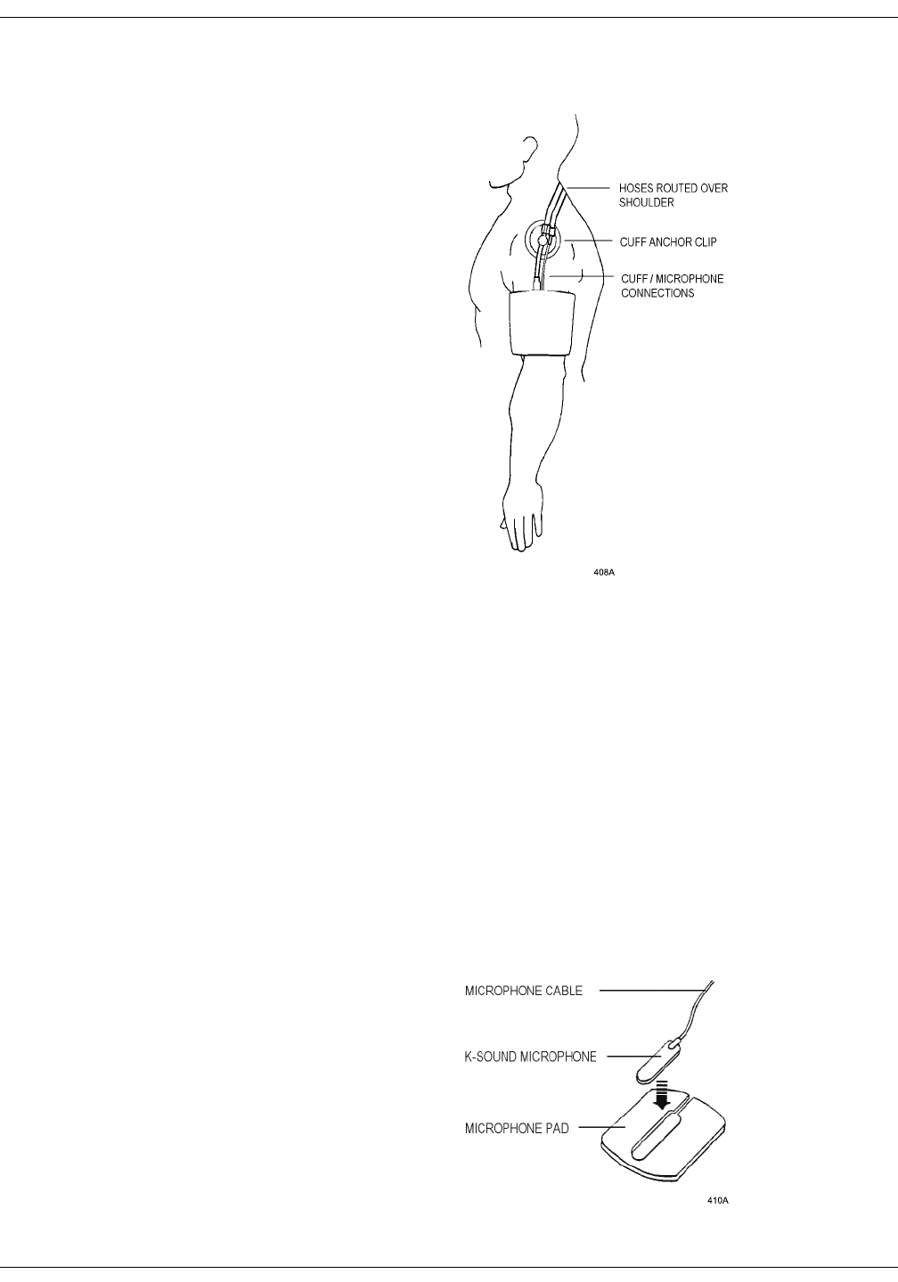
Revision A ApexPro Telemetry System 13-9
2001989-002
NBP Monitoring: Patient Preparation
When attached, the blood pressure cuff and hoses should be positioned
like those in the following illustration.
Patient with Cuff and Hoses Attached
Microphone Placement
A microphone is used to “hear” the Korotkoff sounds (K-sounds) that the
blood pressure monitor uses to determine the systolic and diastolic
pressure readings. The microphone can be placed in a microphone pad
and adhered to the patient’s arm under the blood pressure cuff, or
alternatively, it can be placed directly into the microphone pocket inside
the blood pressure cuff.
Placement in the Microphone Pad
Using a microphone pad is recommended. Place the microphone in the
pad as illustrated below. Do not bend or squeeze the microphone when
placing it in the pad, or when adhering the pad to the patient’s arm.
Placing the Microphone in the Microphone Pad

13-10 ApexPro Telemetry System Revision A
2001989-002
NBP Monitoring: Patient Preparation
Placement in the Blood Pressure Cuff
As already stated, using the microphone pad is recommended, especially
in the case of ambulatory patients or patients with weak K-sounds.
However, as an alternative, the microphone can also be placed directly in
the blood pressure cuff. Follow the directions below.
127(Blood pressure readings taken with the microphone in the blood
pressure cuff may not be as accurate as readings obtained when
using the microphone pad.
1. Remove the bladder from the cuff.
2. Turn the cuff bladder pouch inside out to expose the microphone
pocket.
3. Open the Velcro pocket flap and gently insert the microphone into
the pocket.
4. When the microphone is completely inserted, close the Velcro flap
over the microphone cable and turn the cuff right side out.
5. Replace the bladder and exit the bladder hose and microphone cable
out of the same exit site, either right arm or left arm, as marked on
the cuff.
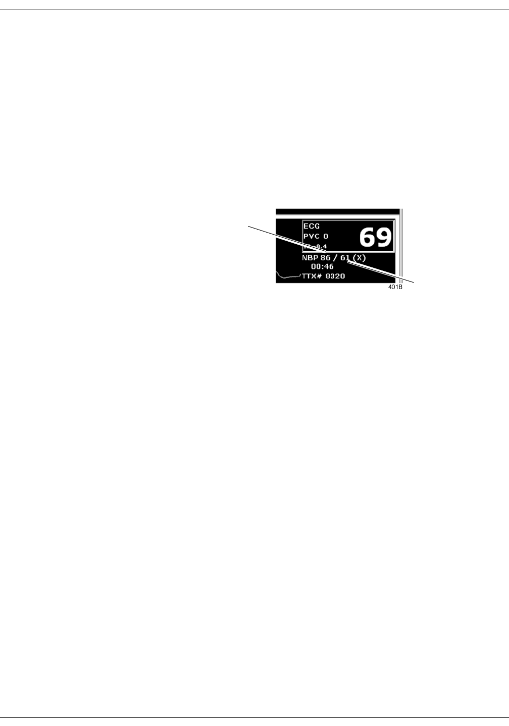
Revision A ApexPro Telemetry System 13-11
2001989-002
NBP Monitoring: NBP Monitoring
NBP Monitoring
NBP in the Multiple Patient Viewer
In the multiple patient viewer, the bed window for a telemetry patient
being monitored for NBP displays an NBP label, along with the systolic
and diastolic values from the most recent measurement.
127(The mean blood pressure value is not measured or calculated
when monitoring blood pressure via telemetry. Therefore, an X
always remains on the display in place of a mean value when a
telemetry patient’s blood pressure is being monitored.
NBP in the Single Patient Viewer
In the single patient viewer, NBP data appears in the View Patient tab
sheet in the same format and location as it does in multiple patient
viewer.
To access the View Patient tab sheet, follow the steps below.
1. Click in the desired patient’s bed window in the multiple patient
viewer. The display rearranges to accommodate the single patient
viewer for that patient.
2. If it is not already visible at the front of the tabs, click on the View
Patient tab to bring the tab sheet to the front.
For more information about the View Patient tab sheet, refer to
Chapter 7, Admit/View a Patient, in this manual.
NBP Limits
You can adjust alarm limits for NBP in the Alarm Control tab sheet for
each patient. For more information on how to set the alarm limits, refer
to Chapter 8, Alarm Control, in this manual.
127(The mean pressure limits can be changed, but there will be no
effect on alarms for telemetry patients because the mean
pressure is not measured or calculated for telemetry patients.
Systolic Value
Diastolic Value
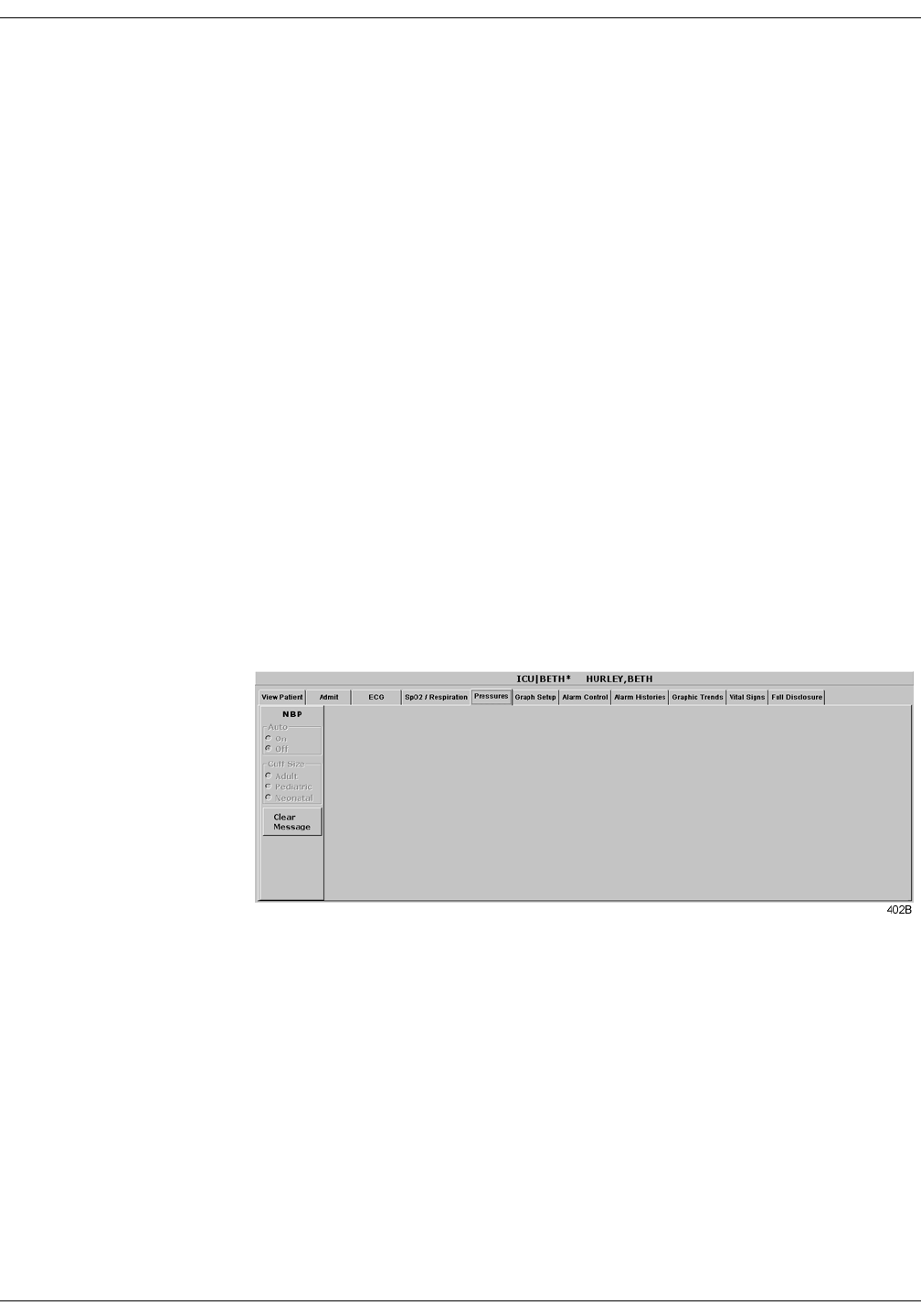
13-12 ApexPro Telemetry System Revision A
2001989-002
NBP Monitoring: Pressures Tab Sheet
Pressures Tab Sheet
The Pressures tab sheet allows you to view and modify settings specific
to the viewed telemetry patient’s NBP display. Settings may be viewed
for any patient. However, you can only modify settings for patients who
are admitted to a bed in your unit.
127(The NBP tab is labeled Pressures because other invasive
pressures settings are available on this tab sheet for bedside
monitored patients only.
Invasive pressure monitoring is not an option for telemetry
patients. Therefore, only NBP information appears on this tab
sheet when monitoring a telemetry patient.
Accessing the Pressures Tab Sheet
To access a patient’s Pressures tab sheet in the single patient viewer,
follow this procedure.
1. Click in the desired patient’s bed window in the multiple patient
viewer. The display rearranges to accommodate the single patient
viewer for that patient.
2. Click on the Pressures tab in the single patient viewer. The Pressures
tab sheet moves to the front.

Revision A ApexPro Telemetry System 13-13
2001989-002
NBP Monitoring: Pressures Tab Sheet
Auto
The interval for automatic NBP measurements is controlled at the blood
pressure monitor, not at the clinical information center. Because the
control is in the blood pressure monitor, the Auto option is inactive for
telemetry patients and appears dimmed.
Cuff Size
The Cuff Size option is inactive for telemetry patients and appears
dimmed.
Clear Message
If you want to remove the displayed NBP values, use the mouse to click
on the Clear Message button. The values are replaced with Xs. Any
Message, Advisory, and Warning level NBP alarms are also cleared.

13-14 ApexPro Telemetry System Revision A
2001989-002
NBP Monitoring: Troubleshooting
Troubleshooting
Problem: Erroneous NBP
measurement Solution:
1. Check for proper cuff size:
Too small a cuff can give an erroneously high value.
Too large a cuff can give an erroneously low value.
2. Check for residual air left in the cuff from a previous measurement.
This could indicate a hardware problem that may require service.
3. Make sure the cuff is not too tight or too loose.
4. Make sure the cuff and the heart are at the same level; otherwise
hydrostatic pressure will offset the NBP value.
5. Watch for pulsus paradoxis.
6. Check for leak in cuff or tubing.
7. Patient may have a weak pulse.
8. Calibration may be necessary.
NBP Status Messages
Below is a list of system status alarm messages that may be displayed in
the patient’s bed window during monitoring.
NBP status messages appear in abbreviated form in graph headers,
when applicable.
A message will clear when the next measurement is initiated, or a
message can be cleared manually with the Clear Message option on the
NBP tab sheet.
CHANGE BATTERY
An NBP measurement was attempted with low batteries. Change the
batteries in the blood pressure monitor and try another measurement.
FAIL
A hardware failure has been detected in the blood pressure monitor. In
the United States, contact GE Marquette Service. Outside the United
States, contact your local sales/service representative.
LEAK
The NBP cuff is loose or there is an air leak in the cuff or tubing. Check
that the cuff is on snugly. Check the connection between the cuff and the
tubing. Check the connection between the tubing and the blood pressure
monitor. Try another measurement. If the problem persists, contact your
local sales/service representative.

Revision A ApexPro Telemetry System 13-15
2001989-002
NBP Monitoring: Troubleshooting
LOW INFLATION PRESS
This message appears when K-sounds are detected immediately upon
inflation. The inflation pressure is too low for proper NBP measurement.
Try another measurement or adjust dynamic/fixed inflate. Refer to the
Setting Test Parameters section in this chapter for more information. If
the problem persists, contact your local sales/service representative.
MOVEMENT
This message appears when there is excessive patient arm movement, or
if the patient’s arm was bent during the measurement. Check the patient
and try another measurement.
SENSOR?
This message appears when the K-sounds on the measurement were too
weak, or not enough sounds were detected. Reposition the microphone
and try another measurement. This message can also appear if the
deflate rate is not properly adjusted. Refer to Setting Test Parameters in
this chapter for more information. If the problem persists, contact your
local sales/service representative.
WEAK PULSE
The patient’s heart rate is erratic. Check that the microphone cable is
plugged firmly into the patient cable, and check that the microphone is
positioned correctly on the patient. Try another measurement. If the
problem persists, it could indicate a defective microphone, microphone
cable, or patient cable. Contact your local sales/service representative.

13-16 ApexPro Telemetry System Revision A
2001989-002
NBP Monitoring: Troubleshooting
For your notes

Revision A ApexPro Telemetry System 14-1
2001989-002
14 Appendices
Appendix A — Message Glossary . . . . . . . . . . . . . . . . . . . . . . . . . . . . . . . . . . . . . 14-3
Alarm Messages . . . . . . . . . . . . . . . . . . . . . . . . . . . . . . . . . . . . . . . . . . . . . . . . .14-3
Graph Messages . . . . . . . . . . . . . . . . . . . . . . . . . . . . . . . . . . . . . . . . . . . . . . . . .14-5
Transmitter-Related Messages . . . . . . . . . . . . . . . . . . . . . . . . . . . . . . . . . . . . . .14-5
System Status Messages . . . . . . . . . . . . . . . . . . . . . . . . . . . . . . . . . . . . . . . . . 14-6
Patient Status Messages . . . . . . . . . . . . . . . . . . . . . . . . . . . . . . . . . . . . . . . . . . .14-6
Appendix B — Supplies . . . . . . . . . . . . . . . . . . . . . . . . . . . . . . . . . . . . . . . . . . . . . 14-7
Appendix C — Technical Specifications . . . . . . . . . . . . . . . . . . . . . . . . . . . . . . . . 14-8
ApexPro Transmitter . . . . . . . . . . . . . . . . . . . . . . . . . . . . . . . . . . . . . . . . . . . . . .14-8
Apex Oximeter . . . . . . . . . . . . . . . . . . . . . . . . . . . . . . . . . . . . . . . . . . . . . . . . . 14-12
Accutracker DX Noninvasive Blood Pressure Monitor . . . . . . . . . . . . . . . . . . . 14-13
ApexPro Receiver System . . . . . . . . . . . . . . . . . . . . . . . . . . . . . . . . . . . . . . . . 14-15
ApexPro Antenna System . . . . . . . . . . . . . . . . . . . . . . . . . . . . . . . . . . . . . . . . 14-17
Appendix D — Abbreviations and Symbols . . . . . . . . . . . . . . . . . . . . . . . . . . . . 14-18
Abbreviations . . . . . . . . . . . . . . . . . . . . . . . . . . . . . . . . . . . . . . . . . . . . . . . . . . .14-18
Symbols . . . . . . . . . . . . . . . . . . . . . . . . . . . . . . . . . . . . . . . . . . . . . . . . . . . . . . .14-20


Revision A ApexPro Telemetry System 14-3
2001989-002
Appendices: Appendix A — Message Glossary
Appendix A — Message Glossary
Alarm Messages
The following messages appear in the patient’s bed window at the
clinical information center.
ALARM PAUSE All alarms for this patient have been turned off
for five minutes. This is initiated from the
transmitter. Refer to ALL ALARMS OFF.
ALL ALARMS OFF All alarms for this patient have been turned off.
No graph strips run, arrhythmia events are not
stored, and no audible tones sound if an alarm
condition should occur.
127(Refer to the Arrhythmia
section in Chapter 11, ECG
Monitoring.
ARR OFF The arrhythmia program for a selected patient
has been turned off. No arrhythmia messages
are displayed, no graph strips run, and no
audible tones sound if an arrhythmia alarm
condition occurs.
ARTIFACT
ARR SUSPEND All artifact begins at level 1. Sustained artifact
progresses to level 2 when noise on ECG lasts
for 20 of the last 30 seconds.
Level 1—Upon immediate detection of
artifact, the message ARTIFACT is
displayed. There is no alarm tone.
Level 2—Arrhythmia monitoring is
suspended in this condition. Heart rate and
PVC values change to X, an additional
message, ARR SUSPEND, is displayed, and
a system warning alarm (repeating foghorn
tone) is heard.
LEADS FAIL All leads have failed. A repeating, low-pitched
foghorn tone will sound. This will self-silence if
condition is corrected, or the user can silence for
one minute with the Silence Alarms button at
the bottom of the CIC display.

14-4 ApexPro Telemetry System Revision A
2001989-002
Appendices: Appendix A — Message Glossary
NO TELEM The NO TELEM alarm occurs in two situations:
127(Refer to the Suspended
Analysis warning in the
Arrhythmia section of Chapter 11,
ECG Monitoring.
1. The patient moves out of range.
Transmitter is out of range. A repeating,
low-pitched foghorn tone sounds after
sensing NO TELEM for 30 seconds. The
Silence Alarms button silences this alarm
for 60 seconds. If, after one minute, the NO
TELEM alarm condition is still present, the
alarm sounds again. Use the Alarm Off
Reason option when extended alarm
silencing is desired. Refer to Chapter 8,
Alarm Control, for more information about
this feature. Should a LEADS FAIL
condition occur prior to a NO TELEM
condition, the LEADS FAIL condition takes
priority. The LEADS FAIL message is
displayed along with the NO TELEM
message.
127(Patient must be within
antenna range to receive a
CHANGE BATTERY message.
2. Transmitter batteries are extremely low or
dead.
If batteries are extremely low or completely
dead, the NO TELEM message appears, a
CHANGE BATTERY message appears in
the patient’s bed window, and the audible
alarm sounds. Activating the ALL ALARMS
OFF feature prevents the audible alarm
from sounding.
OFF NETWORK In the Combo mode, telemetry patient data is
provided from the bedside monitor to the clinical
information center. If the bedside monitor is
removed from the network or becomes otherwise
unavailable, the OFF NETWORK alarm is
generated. The clinical information center will
then display patient data directly from the
telemetry bed along with this message in that
clinical information center bed window. This
alarm sounds a one-beep Advisory alarm tone.
Should the bedside monitor reappear on the
network, the Combo monitoring application will
automatically resume and the alarm will be
cleared.
This alarm is also generated if the receiver
system is removed from the network or becomes
otherwise unavailable. The bedside monitor
does not sound alarms, but the alarms must be
turned back on at the bedside monitor if they
were previously paused or off.

Revision A ApexPro Telemetry System 14-5
2001989-002
Appendices: Appendix A — Message Glossary
Graph Messages
The following messages appear in the patient’s bed window on the
clinical information center display. These relate to running graphs at the
printer.
Transmitter-Related Messages
The following messages appear in the patient’s bed window on the
clinical information center display.
GRAPH ALARM An alarm graph was initiated and is running.
GRAPH MANUAL A manual graph was requested and is
running.
GRAPH TTX The Graph button on the transmitter was
pressed and a 20-second graph strip is
running.
PRINTING A non-real time graph is currently being
printed.
SAVING An alarm or a manual graph has been
requested but the writer is in use, the writer
door is open, or the writer is out of paper. The
request is saved and will run as soon as the
writer is available.
CHANGE BATTERY This message flashes when the batteries are
low. There is approximately 1 hour of use left
after this message appears. If the batteries
are extremely low or completely dead, a NO
TELEM message flashes, and an audible
alarm sounds.
LEADS FAIL All leads have failed. A repeating, low-pitched
foghorn tone sounds. This will self-silence if
condition is corrected, or user can silence for
one minute with Silence Alarms button.
RA (LA, LL, V) FAIL One of these may appear, indicating failure of
a lead.
NO TELEM When the receiver can no longer reliably
receive patient signals from the programmed
transmitter, patient waveforms and heart
rate are removed from the display. If this
condition persists, call service.

14-6 ApexPro Telemetry System Revision A
2001989-002
Appendices: Appendix A — Message Glossary
System Status Messages
System status alarms (generated by mechanical conditions) are
displayed in the lower left corner of the clinical information center
screen. Each message is preceded by the receiver system’s name, if it has
been entered, or a name created by using the last six numbers of the
receiver system Ethernet address. If necessary, call service (refer to
“How to Reach Us” at the front of the manual).
Patient Status Messages
Patient status messages are also displayed in the lower left corner of the
clinical information center screen. They are not, however, preceded by
the receiver system name or Ethernet address.
DUPLICATE TOWER
NAME A network problem exists. Restart the system.
Call service to correct this problem.
DUPLICATE NAME A network problem exists. Restart the system.
Call service to correct this problem.
“Unit/Bed” IS
UNMONITORED A telemetry patient is admitted but is not
displayed (and therefore is unmonitored) on
any clinical information center. If an alarm
occurs on an unmonitored bed, the
information will appear in the alarm text line
and an audible tone will sound. You must
view the patient first if you would like to
silence the alarm. To view an unmonitored
bed, click on the View Other button. (Refer to
Chapter 7, Admit/View a Patient for more
information on viewing a patient.)
“Unit/Bed”:
DUPLICATE NAME There is another device on the network with
the same bed name. The duplicate device
must be renamed.

Revision A ApexPro Telemetry System 14-7
2001989-002
Appendices: Appendix B — Supplies
Appendix B — Supplies
To ensure patient safety, use only supplies manufactured or
recommended by GE Marquette Medical Systems, Inc. Your local sales
representative can provide current supplies lists, or you can contact GE
Marquette Supplies. (Refer to “How to Reach Us” at the front of this
manual.)

14-8 ApexPro Telemetry System Revision A
2001989-002
Appendices: Appendix C — Technical Specifications
Appendix C — Technical Specifications
Below are the technical specifications for the ApexPro telemetry system.
Due to continual product innovation, GE Marquette designs and
specifications are subject to change without notice. Contact your sales/
service office for the most current information.
ApexPro Transmitter
Performance Specifications
Battery type: ANSI/NEDA 15A, 1.5 V AA alkaline (2 req.)
Battery life: 40 hours typical
Polarity: Electronic reverse polarity protection
Static withstand: Meets and exceeds IEC 801-2 second edition
Shock withstand: 5 random drops from 4 ft onto tiled concrete floor
Water resistance: IEC 529 IPX3 rating
Cleaning/Sterilization: Isopropyl alcohol, ammonia (diluted), Cidex,
sodium hypochlorite bleach (diluted) or mild soap (diluted).
Alarms and Controls
Battery integrity: Transmitted and indicated via LED
Lead fail indication: Transmitted and indicated via LED
Alarm Pause: Transmitted and indicated via LED
Graph request: Transmitted
Power on/off: Battery insertion/removal
Transmission
Channel spacing: 25 kHz
Frequency stability: ± 0.0001% of assigned channel frequency
Modulation: GMSK
Bit rate: 10 kb/sec
Antenna: Formed by leadwire shield
Frequency range:
(programmable synthesizer) Power output:
Meets FCC requirements
Part 15.242
560.025 – 613.975 MHz Meets FCC requirements
Part 15.242
420 – 460 MHz As per country specifications

Revision A ApexPro Telemetry System 14-9
2001989-002
Appendices: Appendix C — Technical Specifications
ECG
Multi-channel (5- or 6-leadwire) configuration: I, II, III, Va, Vb, aVR,
aVL, aVF
Leads analyzed simultaneously: Four (I, II, III and V)
Single-channel (3-leadwire) configuration: I, II or III, programmable
Heart rate detection range: 3 to 300 beats/minute
QRS detection range: 0.5 to 5 mV
Frequency response: 0.05 Hz to 40 Hz (–3dB)
Dynamic range: ± 5 mV (RTI)
Input offset: ± 400 mV (RTI)
Input impedance: 15 Megohm min differential at 10 Hz
ECG gain selection: 5, 10, 20, 40 mm/mV (RTI)
Gain accuracy: ± 5% at 15 Hz
Common mode rejection: 100 dB min at 60 Hz
Lead fail detection: DC type; indicates leadwire failed (i.e., RA, LA, LL,
Va, or Vb)
Pacemaker detection: ± 2 mV to ± 700 mV (RTI); 100 µsec to 2 msec;
either polarity
Defibrillator protection: ± 5000 VDC, 360 joules into 50 ohm load
Defibrillation recovery time: Limited only by electrode recovery time.
Transmitter recovers within 2 sec.
Analog/Digital
A/D converter resolution: 10 bits, 9.76 µV (RTI)
Sample rate: 240 samples/sec
Serial communications: 2 – 9600 baud asynchronous
Environmental Specifications
Operating conditions
Ambient temperature: 0°C to 50°C (32°F to 122°F)
Relative humidity: 5% to 95% (noncondensing)
Storage conditions
Temperature: –40°C to 70°C (–40°F to 158°F)
Relative humidity: 30% to 95% (noncondensing)
Pressure: 700 hPa to 1060 hPa
Physical Specifications
Height: 13.7 cm (5.4 in)
Width: 7.4 cm (2.9 in)
Depth: 2.3 cm (0.9 in)
Weight: 141.8 g (5 oz) Weight excludes batteries and leadwire assembly.
Certification
560.025 – 613.975 MHz – FCC Part 15.
UL 2601-1.
Warranty
Standard warranty is one year.* Other options are available.
* Unit must be returned to the factory with freight prepaid.

14-10 ApexPro Telemetry System Revision A
2001989-002
Appendices: Appendix C — Technical Specifications
Electromagnetic Compatibility Compliance
Radiated RF Immunity Verification Results
The ApexPro telemetry system meets the requirements of EN60601-1-2
(1993-04) Medical Electrical Equipment, Part 1: General
Requirements for Safety, 2. Collateral Standard: Electromagnetic
compatibility – Requirements and tests, with the following
exceptions.
127(This data was collected December 6 - 8, 1999.
Exceptions:
EN60601-1-2 Second Edition Draft 200X-YY clause 2.210 Exclusion
bands for intentional radiating/receiving devices = +/- 5% of
frequency or frequency band.
EN60601-1-2 Second Edition Draft 200X-YY clause 36.202.3 - a - 4 –
Radiated RF Electromagnetic fields Immunity - Exclusion Band
EN60601-1-2 Second Edition Draft 200X-YY clause 36.202.6 - a - 4 –
Conducted RF Electromagnetic fields Immunity - Exclusion Band
The antenna system tested operates in a frequency band of 560 - 614
MHz. The allowable exclusion band would then be 532 - 645 MHz.
The level of compliance is not 1 V/m in the ranges of 520 - 534 MHz
and 645 - 660 MHz.
The transmitter tested operates at a frequency of 614 MHz. The
allowable exclusion band would then be 583 - 645 MHz. The level of
compliance is 1 V/m.
If operating under the conditions defined in EMC Standard EN60601-1-2
(Radiated Immunity 3 V/m), field strengths above 1 V/m may cause
waveform distortions and erroneous numeric data at various
electromagnetic interference (EMI) frequencies.
Recommendations:
Review the AAMI EMC Committee technical information report
(TIR-18) titled Guidance on electromagnetic compatibility of medical
devices for clinical/biomedical engineers - Part 1: Radiated radio-
frequency electromagnetic energy. This TIR provides a means to
evaluate and manage the EMI environment in the hospital.
The following actions can be taken:
Manage (increase) distance between sources of EMI and
susceptible devices.
Manage (remove) devices that are highly susceptible to EMI.
Reduce power from internal EMI sources under hospital control
(i.e., paging systems).
Label devices susceptible to EMI.
Educate staff (nurses and doctors) to be aware of and to recognize
potential EMI-related problems.

Revision A ApexPro Telemetry System 14-11
2001989-002
Appendices: Appendix C — Technical Specifications
FCC Compliance Information Statement
This device complies with Part 15 of the FCC Rules and with RSS-210 of
Industry Canada.
Operation is subject to the following two conditions:
1. This device may not cause harmful interference, and
2. This device must accept any interference received, including
interference that may cause undesired operation.
:$51,1*
Changes or modifications not expressly approved by the
party responsible for compliance could void the user’s
authority to operate the equipment.

14-12 ApexPro Telemetry System Revision A
2001989-002
Appendices: Appendix C — Technical Specifications
Apex Oximeter
Performance Specifications
Battery Type: ANSI/NEDA 15A, 1.5V AA alkaline (2 required)
Battery Life: 30 hrs. typical with display on continuously; 60 hrs. typical
with display off
Polarity: Electronic reverse polarity protection
Static withstand: Meets and exceeds IEC 802.2 second edition
Shock withstand: 5 random drops from 4 ft onto tiled concrete floor
Water resistant with sensor in place
Cleaning/Sterilization: Isopropyl alcohol, ammonia (diluted), Cidex,
sodium hypochlorite bleach (diluted) or mild soap (diluted).
Controls and Indicators
Power on/off: Button switch
Display on/off: Button switch
LED indicator: Numerical SPO2 value; numerical HR value; signal
quality indicator
SPO2 sensors: Full line of Nonin qualified reusable and disposable
sensors
Processing
Saturation range: 0 to 100%
Saturation accuracy: 70 to 100% ± 3 digits (± 1 S.D.)
Pulse rate range: 18 to 300 BPM
Pulse rate accuracy: ± 3 % or 1 BPM, whichever is greater
Central Display
Messages: Check probe, Low signal quality, Probe off patient
Numerical display: SPO2 (% value), HR (bpm)
Alarms: SPO2 high/low, HR high/low
Physical Specifications
Height: 12.7 cm (5.0 in)
Depth: 2.0 cm (0.8 in)
Width: 6.9 cm (2.7 in)
Weight: 113.4 g (4.0 oz)
Weight excludes batteries and SPO2 probe
Certification
UL 2601-1
CE marking for the 93/42/EEC Medical Device Directive.
Warranty
Standard warranty is one year.* Other options are available.
* Unit must be returned to the factory with freight prepaid.
The Apex Oximeter is manufactured for GE Marquette Medical Systems
by Nonin Medical, Inc. It is recommended for use with Nonin sensors
only.

Revision A ApexPro Telemetry System 14-13
2001989-002
Appendices: Appendix C — Technical Specifications
Accutracker DX Noninvasive Blood Pressure Monitor
Performance Specifications
Technique: Ausculatory. Diastolic pressure is determined from Phase 5
Korotkoff sounds.
Accuracy: Blood pressure measurements determined with this device are
equivalent to those obtained by a trained observer using the cuff/
stethoscope auscultation method, within the limits prescribed by the
American National Standard, Electronic or automated
sphygmomanometers.
Pressure: Dynamic or fixed programmable. Dynamic pressure
configuration maximizes patient comfort by limiting cuff inflation to
30 mmHg greater than the previous systolic pressure, without
exceeding configurable limits.
Pressure Range: 0 to 250 mmHg
Maximum pressure programmable limits: 100 to 250 mmHg,
increments of 10 mmHg
Minimum pressure programmable limits: 10 to 100 mmHg,
increments of 10 mmHg
Auto retry: Automatically initiates an additional reading in the event a
reading fails to satisfy any of the programmable criteria.
127(Contact technical support
for information on setting these
limits.
Blood Pressure Range:
Systolic: 10 to 250 mmHg
Upper auto-retry programmable limits: 50 to 240 mmHg,
increments of 10 mmHg*
Lower auto-retry programmable limits: 50 to 150 mmHg,
increments of 10 mmHg*
Systolic change (delta) limits: 30 to 100 mmHg, increments of 10
mmHg*
Diastolic: 10 to 250 mmHg
Upper auto-retry programmable limits: 50 to 150 mmHg,
increments of 10 mmHg*
Lower auto-retry programmable limits: 30 to 100 mmHg,
increments of 10 mmHg*
Diastolic change (delta) limits: 20 to 100 mmHg, increments of 10
mmHg*
Pulse Pressure
Upper auto-retry programmable limits: 40 to 150 mmHg,
increments of 10 mmHg*
Lower auto-retry programmable limits: 10 to 100 mmHg,
increments of 10 mmHg*
Pulse pressure change (delta) limits: 30 to 100 mmHg,
increments of 10 mmHg*
Deflation rate: True linear deflation according to AHA guidelines.
Programmable for 2, 3, 4, 5, or 6 mmHg per second.
Display: 32 character LCD (16 characters per row) provides a clear view
of data and message prompts.
Sample quantity: Over 250 samples per set of 4 new batteries.

14-14 ApexPro Telemetry System Revision A
2001989-002
Appendices: Appendix C — Technical Specifications
Sample periods: Manual and interval programmable. Intervals of 5, 6, 7,
8, 9, 10, 15, 20, 25, 30, 35, 40, 45, 50, 55, 60, 90, 120 or 240 minutes
can be selected/programmed.
Start key: Allows the patient or caregiver to initiate readings on demand.
Power source: Four 1.5 (AA) alkaline batteries. Rechargeable batteries
are not recommended (sample quantity with rechargeable batteries
typically limited to 25 samples/measurements vs. 250 samples/
measurements with new alkaline batteries).
Environmental Specifications
Operating temperature: +10ºC to 40ºC (50ºF to 104ºF)
Relative Humidity: <95%
Storage temperature: -20ºC to +50ºC (-4ºF to +122ºF)
Relative Humidity: <95%
Power: 6 Vdc, four 1.5V “AA” Alkaline batteries.
Electromagnetic Compatibility Compliance
The Accutracker DX noninvasive blood pressure monitor complies with
EN60601-1-2 (1993-04) Medical Electrical Equipment, Part 1:
General Requirements for Safety, 2. Collateral Standard:
Electromagnetic compatibility - Requirements and tests.
Exception: IEC 60601-1-2 clause 36.202.1 - Immunity: ESD
The level of compliance is ± 2, 4, 6 kV Contact discharge and ± 2, 4, 6
kV Air discharge.
Air discharges of ± 8 kV or greater may cause the cuff to deflate and the
unit to lock up. By turning the power switch off, then back on (manual
reset), the unit will be restored to the user-defined settings and normal
operation.
Recommendations:
The Accutracker DX blood pressure monitor should be kept in the
carrying pouch supplied with each unit.
Care should be taken to minimize the ESD potential when the
Accutracker DX blood pressure monitor is removed from the pouch.
This includes:
Handling the unit in an ESD-protected area.
Maintaining humidity levels of 50% relative humidity or greater.
Discharging ESD potential on human hands prior to handling
the unit out of the pouch.
Physical Specifications
Length: 12.7 cm (5.0 in)
Width: 8.25 cm (3.25 in)
Thickness: 3.3 cm (1.30 in)
Weight: 357.2 g (12.6 oz)
Accutracker Dx Certification
UL2601
Warranty
1 year

Revision A ApexPro Telemetry System 14-15
2001989-002
Appendices: Appendix C — Technical Specifications
ApexPro Receiver System
Performance Specifications
Quad Receiver Module
Type: GMSK digitally demodulated
Frequency range: 560.025 MHz to 613.975 MHz (U.S.)
420 MHz to 460 MHz (international)
Frequency step resolution: Frequency synthesized tuning to any
transmitter. 25 KHz spacing.
Frequency stability: ±0.00015% of assigned channel frequency
Demodulation: GMSK
Bit rate: 10 kb/sec
Sensitivity: 0.8 µV (–95 dBm) minimum for 1 bit error/1 million bits
received
Receiver Subsystem
Capacity: 1 to 4 quad receiver modules (4 to 16 receivers)
System status indicators: 7 bicolor LEDs
Network
IEEE 802.3 compatible, physical connector via 10 Base T
Serial diagnostics: 19200 baud, 1 stop bit, 8 data bits, no parity, XON/
XOFF flow control
Environmental Specifications
Power requirements: 85 to 264 VAC, 47 to 63 Hz
Power consumption: 25 watts max with 4 quad receiver units
Cooling: Free convection
Operating conditions
Ambient temperature: 0°C to 40° C (32°F to 104°F)
Relative humidity: 10% to 90% (noncondensing)
Storage conditions
Temperature: –40°C to 70°C (–40°F to 158°F)
Relative humidity: 15% to 95% (noncondensing)

14-16 ApexPro Telemetry System Revision A
2001989-002
Appendices: Appendix C — Technical Specifications
Physical Specifications
Subsystem
Height: 170 mm (6.7 in)
Width: 325 mm (12.8 in)
Depth: 250 mm (9.8 in)
Weight: 6.4 kg (14 lb)
Certification
Receiver Unit: FCC Part 15, Subpart B Class B (U.S. only)
Subsystem: UL 2601-1 Listed. IEC 60601-1 Certified.
Warranty
Standard warranty is one year. Other options are available.

Revision A ApexPro Telemetry System 14-17
2001989-002
Appendices: Appendix C — Technical Specifications
ApexPro Antenna System
Performance Specifications
Antenna
Style: Omni-directional
Fields: Four (A, B, C, D)
Diversity: Based on received signal level
Environmental Specifications
Power requirements: 85 to 264 VAC, 47 to 63 Hz
Power consumption: 25 watts max with 4 quad receiver units
Cooling: Free convection
Operating Conditions
Ambient temperature: 10°C to 35°C (50°F to 95°F)
Relative humidity: 25% to 85% (noncondensing)
Storage Conditions
Temperature: –40°C to 70°C (–40°F to 158°F)
Relative humidity: 15% to 95% (noncondensing)
Pressure: 500 hPa to 1060 hPa
Electromagnetic Compatibility Compliance
For important compliance information, refer to the Electromagnetic
Compatibility Compliance information in the ApexPro Transmitter
section of these technical specifications.
Warranty
Standard warranty is one year. Other options are available.

14-18 ApexPro Telemetry System Revision A
2001989-002
Appendices: Appendix D — Abbreviations and Symbols
Appendix D — Abbreviations and Symbols
Abbreviations and symbols you may encounter while reading this
manual or using the ApexPro telemetry system or the clinical
information center are listed below, along with their meanings.
Abbreviations
A
AO2 arterial oxygen saturation
ARRY arrhythmia
ART arterial
Auto, AUTO automatic
AVF left foot augmented lead
AVL left arm augmented lead
AVR right arm augmented lead
B
BP blood pressure
BT blood temperature
C
C Celsius, centigrade
CALCS calculations
cc, CC cubic centimeter
CCU critical care unit
COMM communication
CPP cerebral perfusion pressure
CVP central venous pressure
D
D diastolic
DDW Direct Digital Writer
DIA diastolic
E
ECG electrocardiograph
F
F Fahrenheit

Revision A ApexPro Telemetry System 14-19
2001989-002
Appendices: Appendix D — Abbreviations and Symbols
H
HR heart rate
I
ICP intracranial pressure
ICU intensive care unit
IEEE Institute of Electrical and Electronics Engineers
Inc. incorporated
INT interface
L
LA left arm
LAN Local Area Network
LL left leg
M
M mean
mm/S millimeters per second
mmHg millimeters of mercury
N
NBP noninvasive blood pressure
No. number
NRT non-real time
O
OR operating room
P
PA pulmonary artery
PPR peripheral pulse rate
Q
QRS interval of ventricular depolarization
R
RA right arm
RESP respiration
RL right leg
RR respiration rate

14-20 ApexPro Telemetry System Revision A
2001989-002
Appendices: Appendix D — Abbreviations and Symbols
Symbols
S
S systolic
SpO2, SPO2 arterial oxygen saturation
SP special
SYS systolic
T
T1 temperature site 1
T2 temperature site 2
Temp, TMP temperature
TTX # identification number on back of transmitter
V
V precordial lead
V-Fib, V-FIB ventricular fibrillation
V-Tach, V-TACH ventricular tachycardia
°degrees
% percent
# number

Revision A ApexPro Telemetry System Index-1
2001989-002
Index
Numerics
6-lead monitoring 11-9
A
Aberrant rhythm 10-6
Accutracker DX noninvasive blood pressure
monitor 3-9, 13-3
Battery installation 4-8
Buttons and switches 3-10
Connections 4-10
Setup 13-5
Admitting 7-4–7-6
AFIB (atrial fibrillation) rhythm 10-6
Alarm condition indicators 7-13
Alarm control 8-5–8-11
Alarm defaults 8-16
Alarm help 8-11
Alarm history
Deleting events 10-6
Learn as 10-6
Print directory 10-5
Scanning events 10-5
Viewing events 10-5
Alarm off reason 8-9
Alarm pause 3-7
Alarm pause breakthrough 8-12
Alarm volume 6-14
Apex Oximeter 4-6
Apex Oximeter connections 4-7
Battery installation 4-6
Buttons and LEDs 3-8
ApexPro telemetry system 3-4
ApexPro transmitter
Battery installation 4-3
Buttons and LEDs 3-6
Dust covers 3-7
Pausing alarms 3-7
Arrhythmia 11-19–11-22
Full arrhythmia conditions 11-20
Lethal arrhythmia conditions 11-22
Asystole 11-22
Brady 11-22
V Tach 11-22
VFib/VTach 11-22
Troubleshooting 11-25
Arrhythmia calls
Changing names of 10-7
Artifact 11-12
B
Battery installation
Accutracker DX noninvasive blood pressure
monitor 4-8
Apex Oximeter 4-6
ApexPro transmitter 4-3
Blood pressure monitor 3-9, 13-3
C
CE marking information Notices-1
Compliance Notices-1
Check box controls 1-7
CIC defaults 6-12
CIC setup 6-3
Cleaning
General 5-5
Leadwires 5-7
Transmitters 5-6
Click 1-6
Controls
check boxes 1-7
radio buttons 1-6
scroll bars 1-7
Conventions
Buttons 1-4
Messages/Prompts 1-4
Multiple patient viewer 1-4
Single patient viewer 1-5
Tab options 1-5
Tab sheets 1-5
Tabs 1-5
Current telemetry listings 6-15
D
Default settings 6-4
Unit defaults worksheet 1-9
Discharge instructions 7-7
E
ECG
Electrode placement 11-4
In the multiple patient viewer 11-10
In the single patient viewer 11-11
Patient preparation 11-4
Signal quality 11-8
Skin preparation 11-4
ECG tab sheet
Accessing 11-13
Detect pace 11-15–11-17

Index
Index-2 ApexPro Telemetry System Revision A
2001989-002
Einthoven + V lead electrode placement 11-5
Electrode placement 11-4
3-leadwire 11-6
5-leadwire 11-5
6-leadwire 11-5
Einthoven + V lead electrode 11-5
Modified chest lead (MCL) 11-7
Pacemaker patients 11-8
Pediatric patients 11-6
Equipment inspection 5-4
F
False asystole 11-25
False ventricular calls 11-25
FCC compliance statement 14-11
Full arrhythmia 11-20
G
Graph all patients 9-6
Graph button
IMPACT.wf paging system 3-6, 9-4
Graph control menu 9-11
Graph location defaults 9-8
Graph on alarm 9-13
Graphic trends
Scanning 10-10
Select parameters for graphic trends 10-10
Time resolution 10-10
Trend directory 10-9
Graphing 9-3–9-10
Automatic alarm graphs 9-3
Graph all patients 9-6
Graph location defaults 9-8
Graph messages 9-5
Graph paper out 9-10
Manual graphs 9-4
Stopping a graph 9-9
Transmitter initiated graphs 9-4
I
IMPACT.wf paging system
View on demand 3-6, 9-4
Inaccurate pacemaker detection 11-27
L
Laser printer 9-15
Lead analysis 11-18
Multi-lead analysis 11-18
Single lead analysis 11-18
Leadwires
Cleaning 5-7
Multi-Link leadwire sets 4-5
Storage 5-9
Learn as 10-6
Lethal arrhythmia 11-22
M
Manual graphs 9-4
N
NBP monitoring
In the multiple patient viewer 13-11
In the single patient viewer 13-11
Patient preparation 13-8
Microphone placement 13-9
Normal rhythm 10-6
P
Pacemaker pulse detection 11-16
False calls 11-15
Pace 1 11-16
Pace 2 11-16
Pace help 11-17
Rate meters 11-15
Pacemaker spike 11-15
Pacemaker troubleshooting 11-26
Patient preparation 11-4
Patient status alarms 8-3
Telemetry defaults 8-14
Popup lists 1-8
Pressures tab sheet
Accessing 13-12
Clear message 13-13
R
Radio button control 1-6
Relearn 7-9, 10-7, 11-13
S
Scroll bar controls 1-7
Service password 6-5
Six lead monitoring 11-9
SpO2 monitoring
In the multiple patient viewer 12-6
In the single patient viewer 12-6
Signal strength 12-5
SPO2 tab sheet
Accessing 12-8
Rate 12-8
Size 12-8
ST analysis 11-24
ST deviation alarm 11-24
ST measurement 11-24
ST troubleshooting 11-28
Sterilization
Leadwires 5-7
Telemetry transmitter 5-6
Supplies 14-7
Symbols 14-20
System status alarms 8-4
Telemetry defaults 8-15

Revision A ApexPro Telemetry System Index-3
2001989-002
Index
T
Technical maintenance 5-10
Technical specifications 14-8
Accutracker DX noninvasive blood pressure
monitor 14-13
Apex Oximeter 14-12
ApexPro antenna system 14-17
ApexPro receiver subsystem 14-15
ApexPro transmitter 14-8
Telemetry transmitters
Apex transmitter battery installation 4-4
Setup 3-5
Storage 5-9
Telemetry unit defaults
Changing 6-7
Viewing 6-6
Time focus 10-16
Transmitter graph 9-13
Troubleshooting
NBP 13-14
Pacemaker 11-26
SpO2 messages 12-9
ST 11-28
U
Unit defaults worksheet 1-9
User mode 6-3
V
Ventricular arrhythmia 11-19
View on demand 3-6, 9-4
Viewing a patient 7-9
Viewing another patient 7-10
In the multiple patient viewer 7-11
In the single patient viewer 7-10
Vital signs
Printing 10-13
W
Warnings 2-4


World Headquarters
GE Marquette Medical Systems
8200 West Tower Avenue
Milwaukee, WI 53223 USA
Tel: +414.355.5000
800.558.5120 (US only)
Fax: +414.355.3790
Europe Region
GE Marquette Hellige GmbH
A GE Medical Systems Company
Postfach 60 02 65
D-79032 Freiburg Germany
Tel: +49.761.45.43.0
Fax: +49.761.45.43.233
Asia Pacific
GE Medical Systems Hong Kong Limited
11th Floor, The Lee Gardens
33 Hysan Avenue
Causeway Bay Hong Kong
Tel: +852.2100.6300
Fax: +852.2100.6292