GE Medical Systems Information Technologies SHU-WMTS EA-WMTS-SHU-4 User Manual 2001989 134B
GE Medical Systems Information Technologies Inc. EA-WMTS-SHU-4 2001989 134B
Contents
- 1. System Operators Manual Part 1
- 2. System Operators Manual Part 2
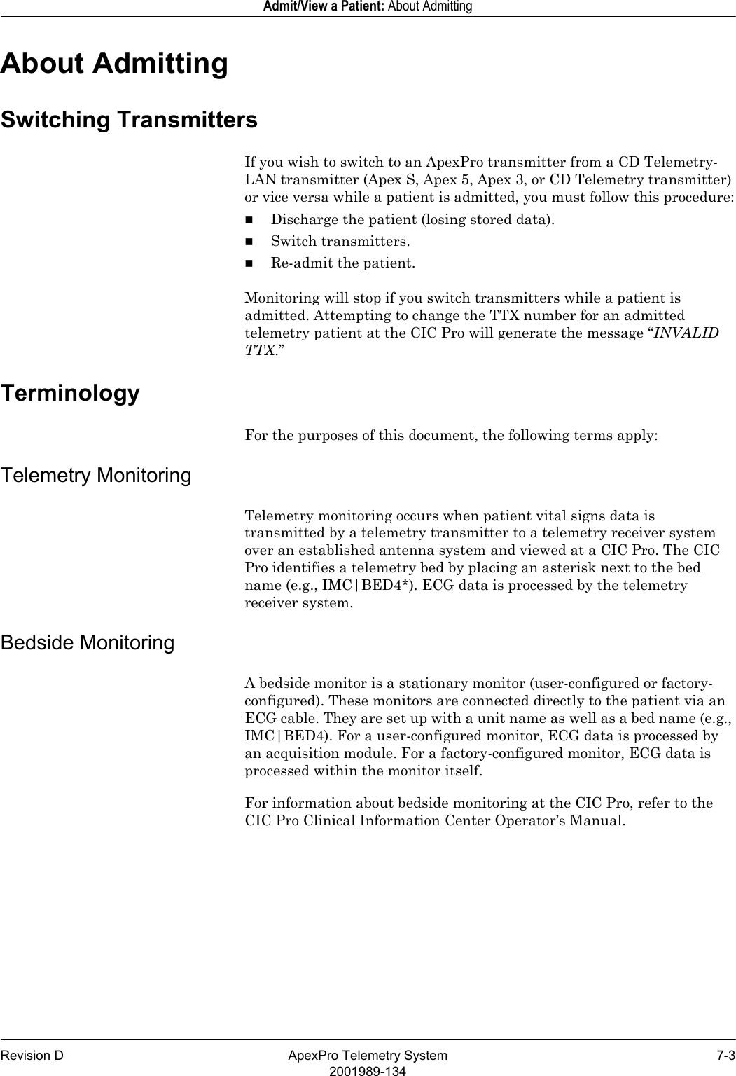
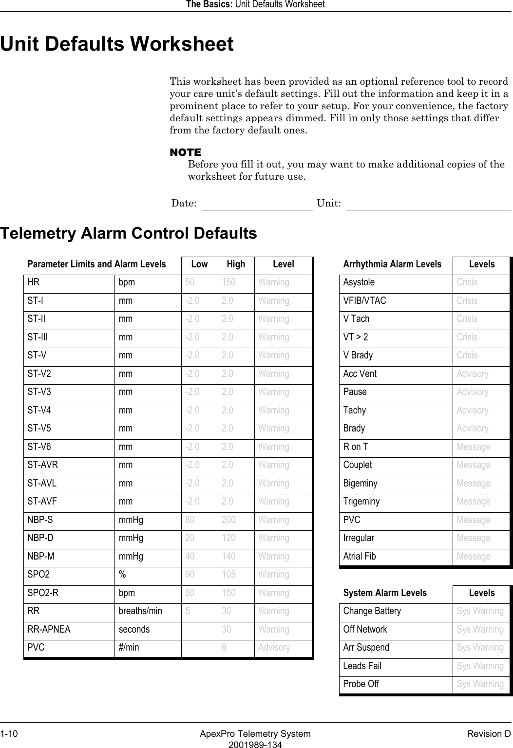
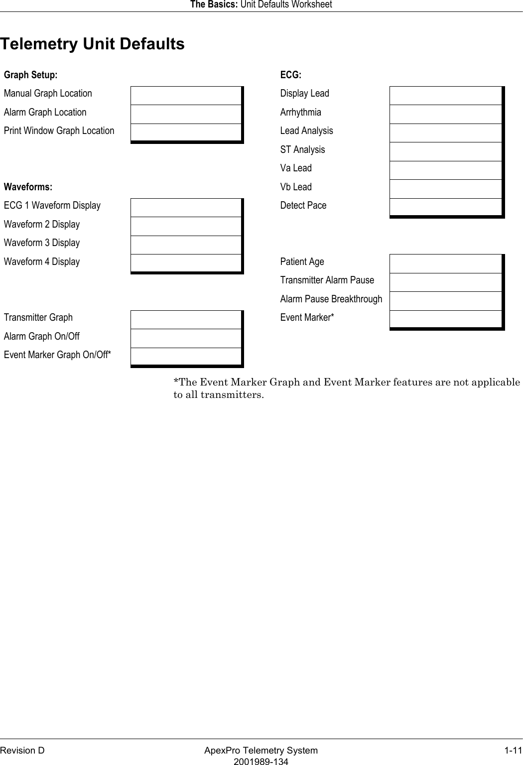
System Operators Manual Part 1
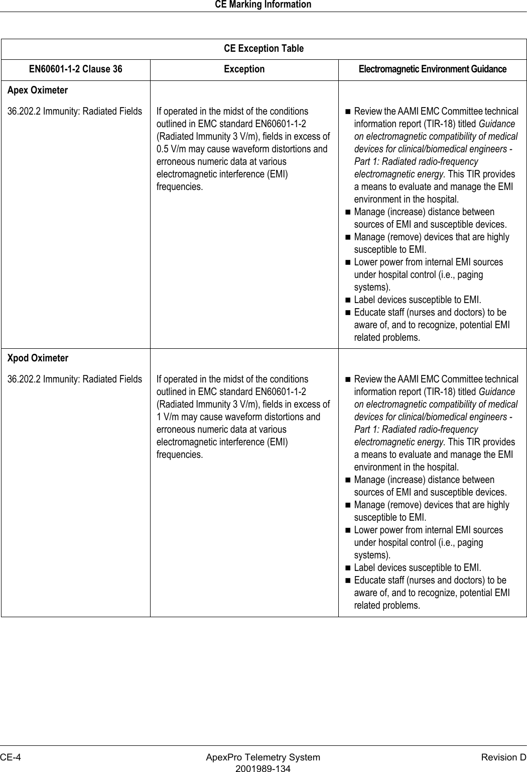
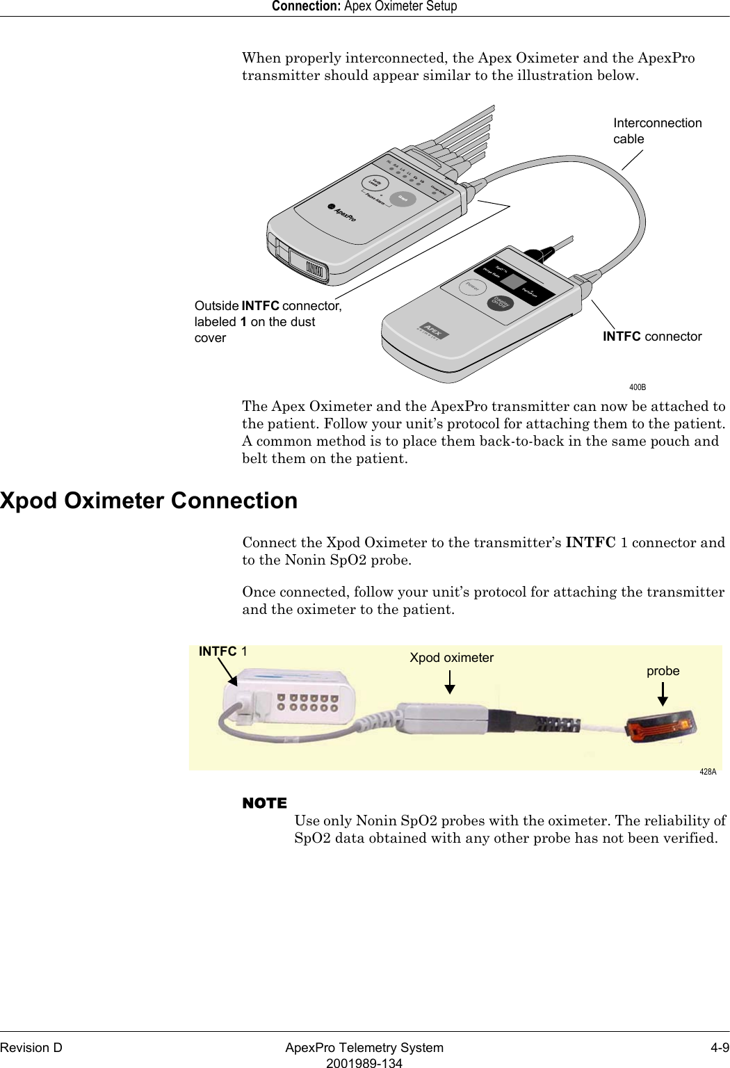
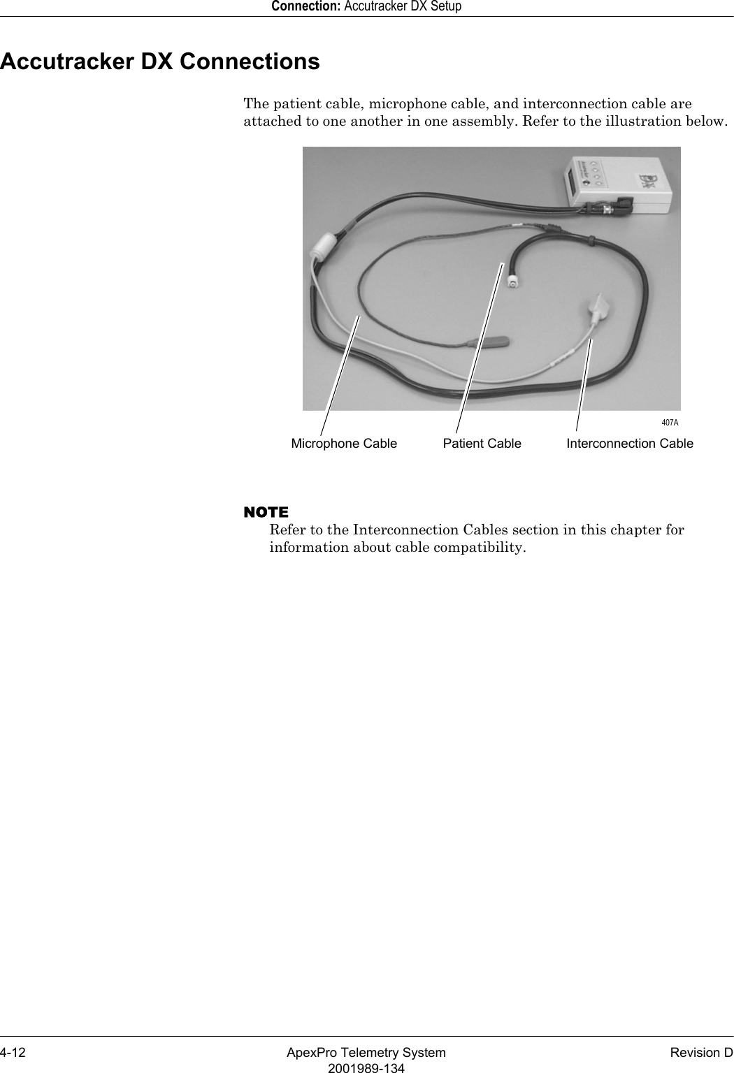
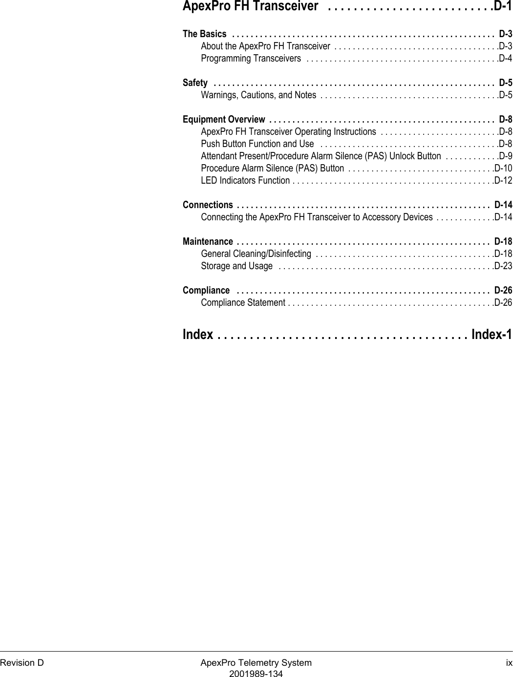
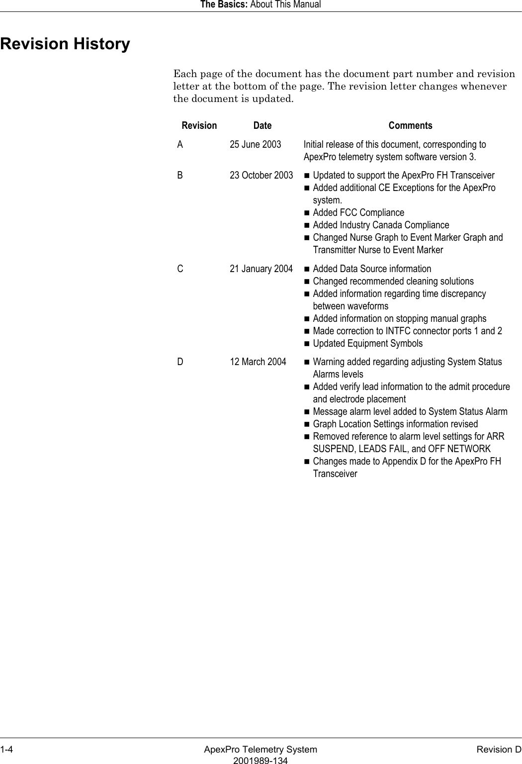
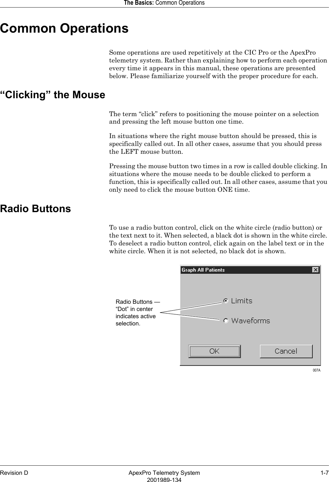
![Revision D ApexPro Telemetry System CE-52001989-134CE Marking InformationRadio and Telecommunication Terminal Equipment DirectiveThe ApexPro telemetry system transmitters bear the CE mark CE 0123 indicating conformity with the provisions of the Council Directive 1999/5/EC of 9 March 1999 concerning R&TTE as tested by MKES BABT Services GmbH Notified Body TUV (0123).The product complies with the requirements of standard EN 300 220-1 [ETSI 300 220-1 v1.3.1]: “Electromagnetic Compatibility and Radio Spectrum Matters (ERM); Short Range Devices (SRD); Part 1: Technical Characteristics and Test Methods”.Accutracker DX NBP Monitor36.202.1 Immunity: ESD Air — Discharges in excess of ±6 Kv may cause the cuff to deflate and the unit to lock up. By turning the power switch off, then back on (manual reset), the unit will be restored to the user-defined settings and normal operation.The Accutracker DX blood pressure monitor should be kept in the carrying pouch supplied with each unit.Care should be taken to minimize the ESD potential when the Accutracker DX blood pressure monitor is removed from the pouch. This includes:Handling the unit in an ESD-protected area.Maintaining humidity levels of 50% relative humidity or greater.Discharging ESD potentials on human hands prior to handling the unit out of the pouch.CE Exception TableEN60601-1-2 Clause 36 Exception Electromagnetic Environment Guidance](https://usermanual.wiki/GE-Medical-Systems-Information-Technologies/SHU-WMTS.System-Operators-Manual-Part-1/User-Guide-840760-Page-7.png)
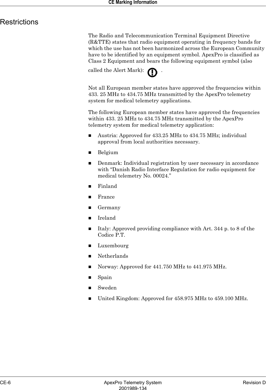
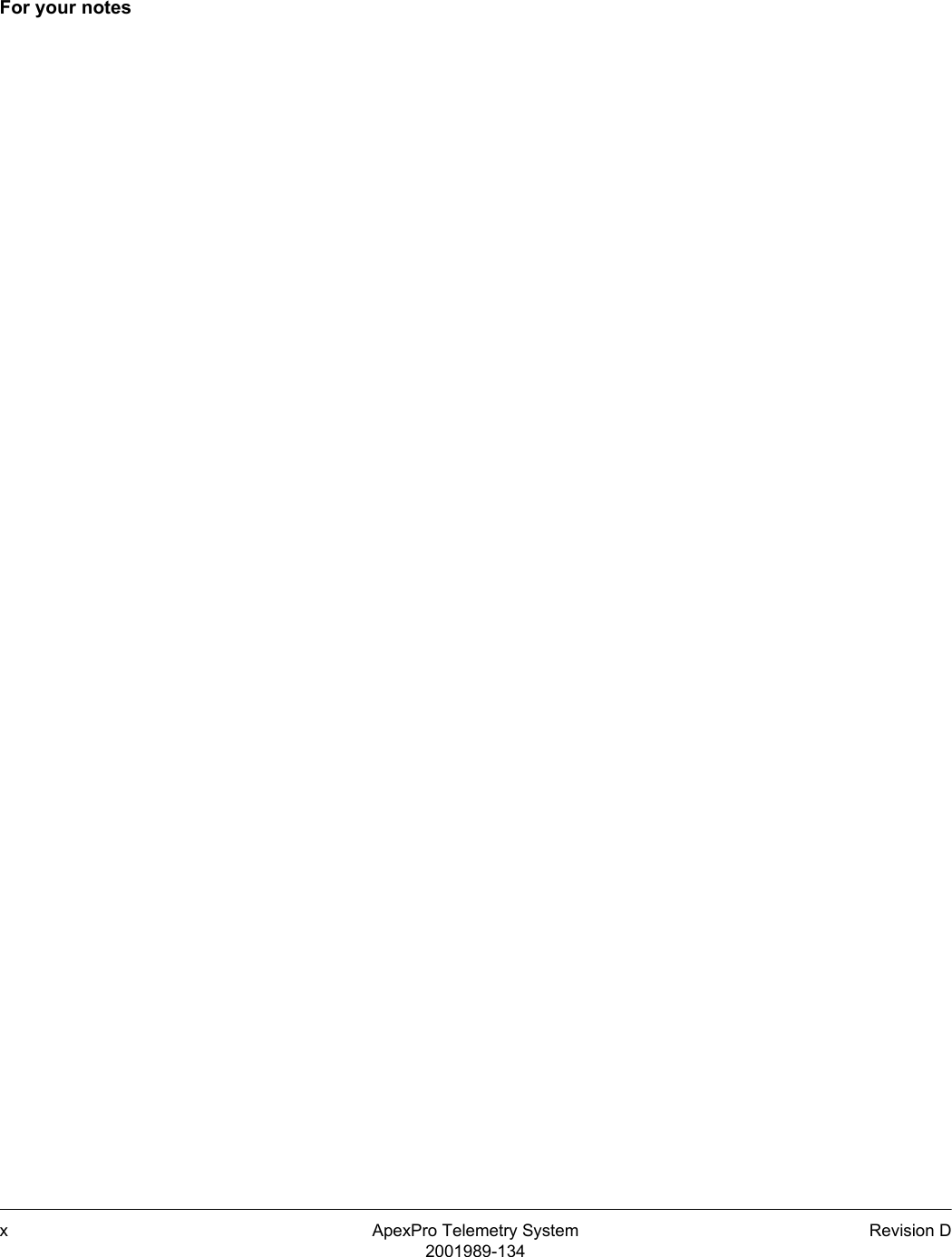

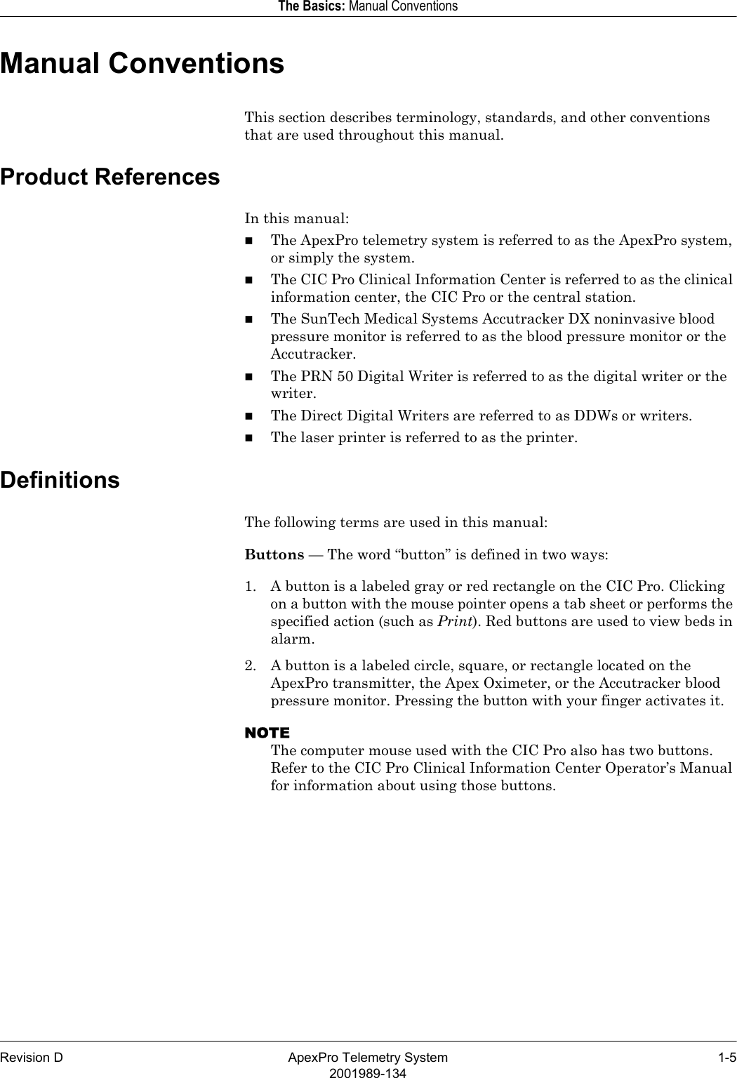
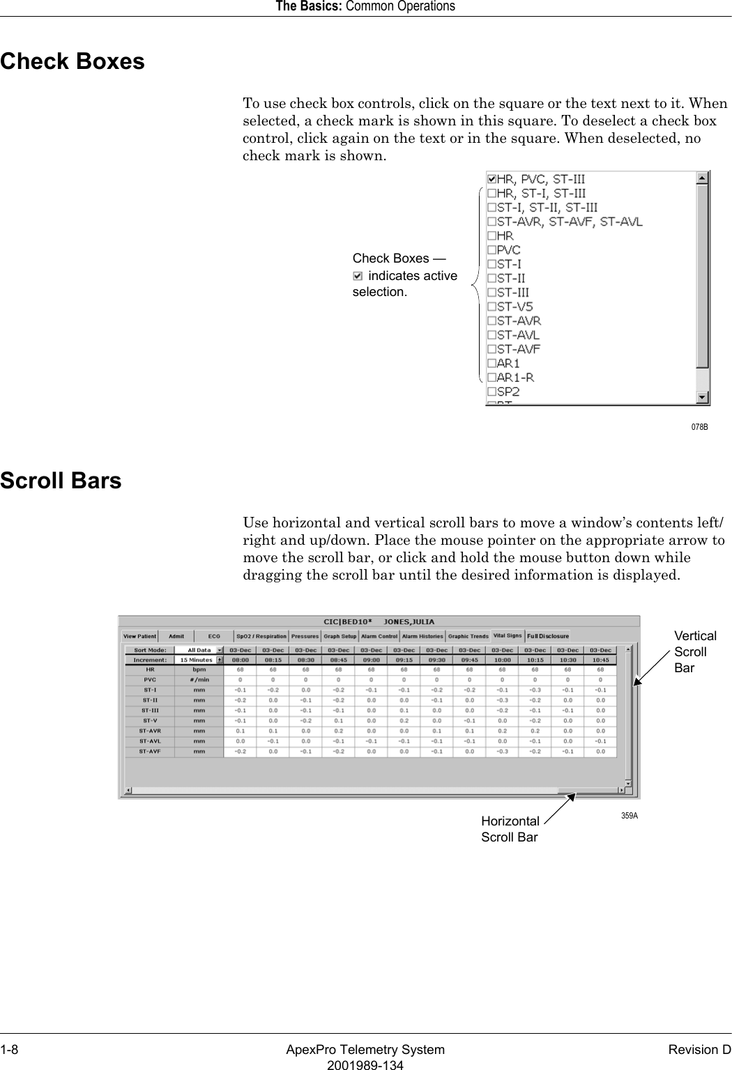


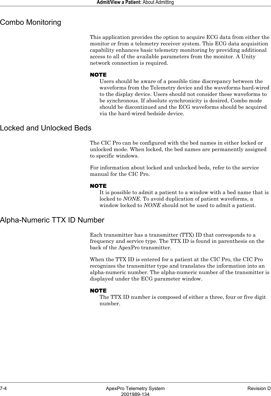
![Revision D ApexPro Telemetry System 2-152001989-134Safety: For Your SafetyEquipment SymbolsNOTESome symbols may not appear on all equipment.ATTENTION: Consult accompanying documents.CAUTION: To reduce the risk of electric shock, do NOT remove cover. Refer servicing to qualified service personnel.TYPE CF APPLIED PART: Isolated (floating) applied part suitable for intentional external and internal application to the patient including direct cardiac application. “Paddles” outside the box indicate the applied part is defibrillator proof.[Medical Standard Definition:] F-type applied part (floating/isolated) complying with the specified requirements of IEC 60601-1/UL 2601-1/CSA 601.1 Medical Standards to provide a higher degree of protection against electric shock than that provided by type BF applied parts.TYPE BF APPLIED PART: Isolated (floating) applied part suitable for intentional external and internal application to the patient excluding direct cardiac application. “Paddles” outside the box indicate the applied part is defibrillator proof.[Medical Standard Definition:] F-type applied part (floating/isolated) complying with the specified requirements of IEC 60601-1/UL 2601-1/CSA 601.1 Medical Standards to provide a higher degree of protection against electric shock than that provided by type B applied parts.NOTEThe rating of protection against electric shock (indicated by symbol for CF or BF) is achieved only when used with patient applied parts recommended by GE Medical Systems Information Technologies.TYPE B APPLIED PART: Non-isolated applied part suitable for intentional external and internal application to the patient excluding direct cardiac application.[Medical Standard Definition:] Applied part complying with the specified requirements of IEC 60601-1/UL 2601-1/CSA 601.1 Medical Standards to provide protection against electric shock, particularly regarding allowable leakage current.FuseEquipotential Stud: A ground wire from another device can be tied here to ensure the devices share a common reference.](https://usermanual.wiki/GE-Medical-Systems-Information-Technologies/SHU-WMTS.System-Operators-Manual-Part-1/User-Guide-840760-Page-47.png)