GE Medical Systems Information Technologies SHU-WMTS EA-WMTS-SHU-4 User Manual 2001989 134B

GE Medical Systems Information Technologies Inc. EA-WMTS-SHU-4 2001989 134B

Contents

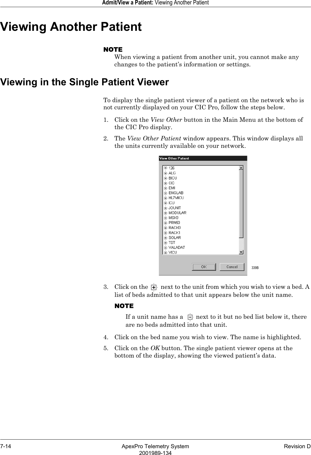
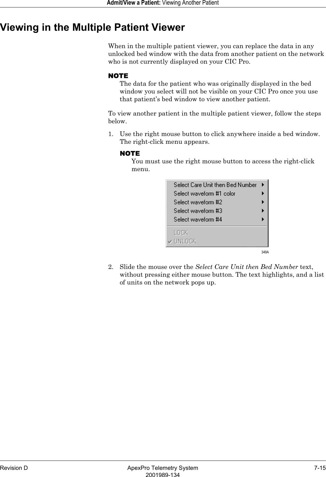
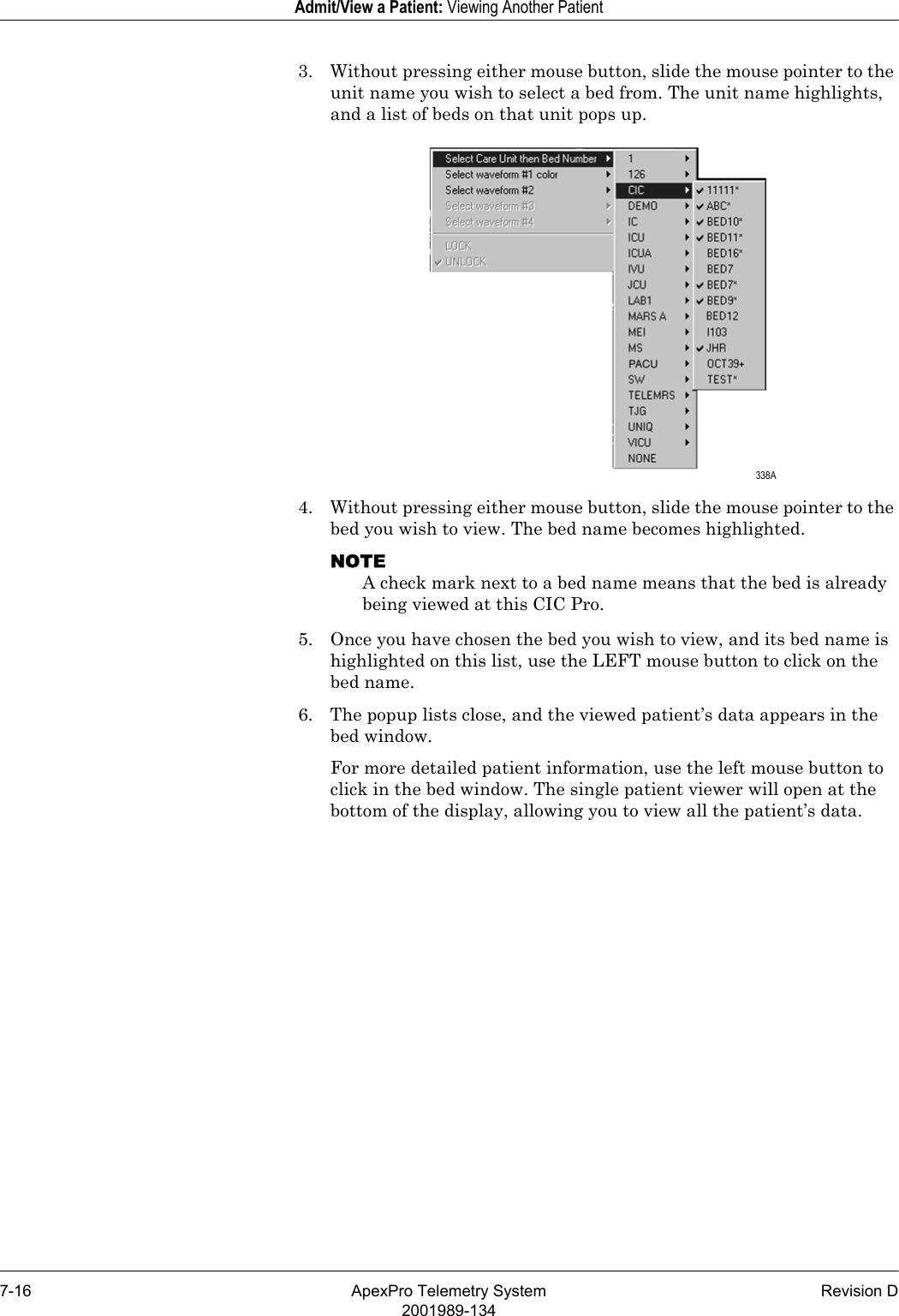
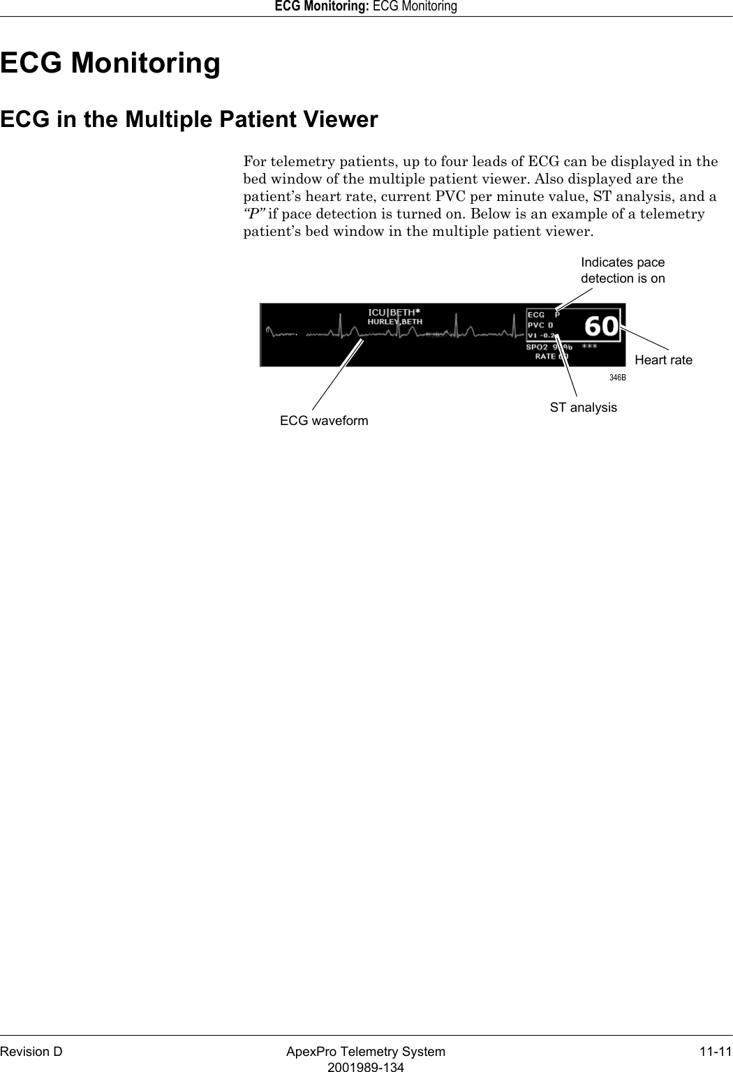
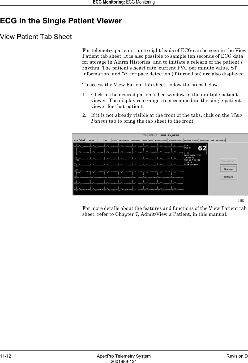
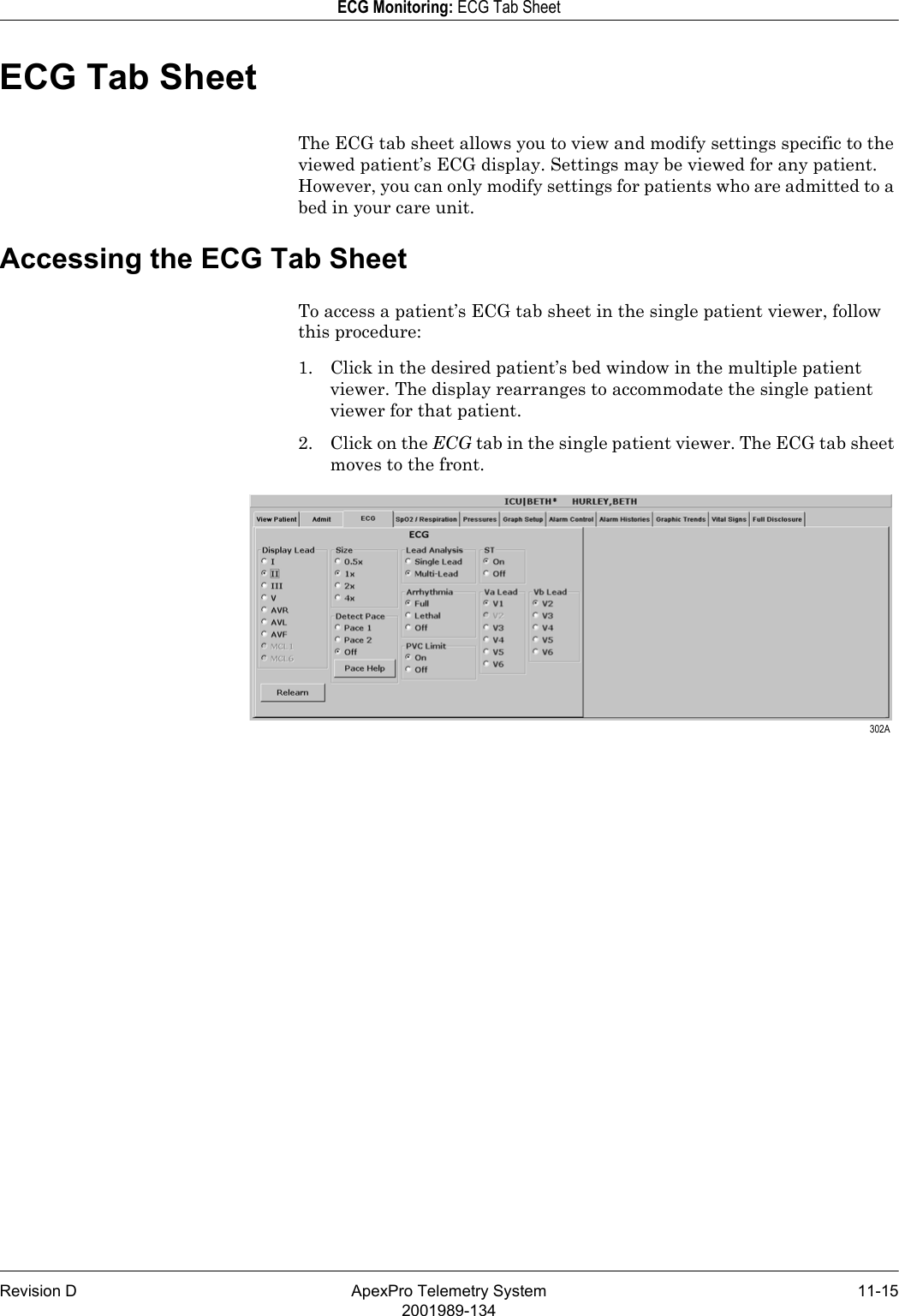
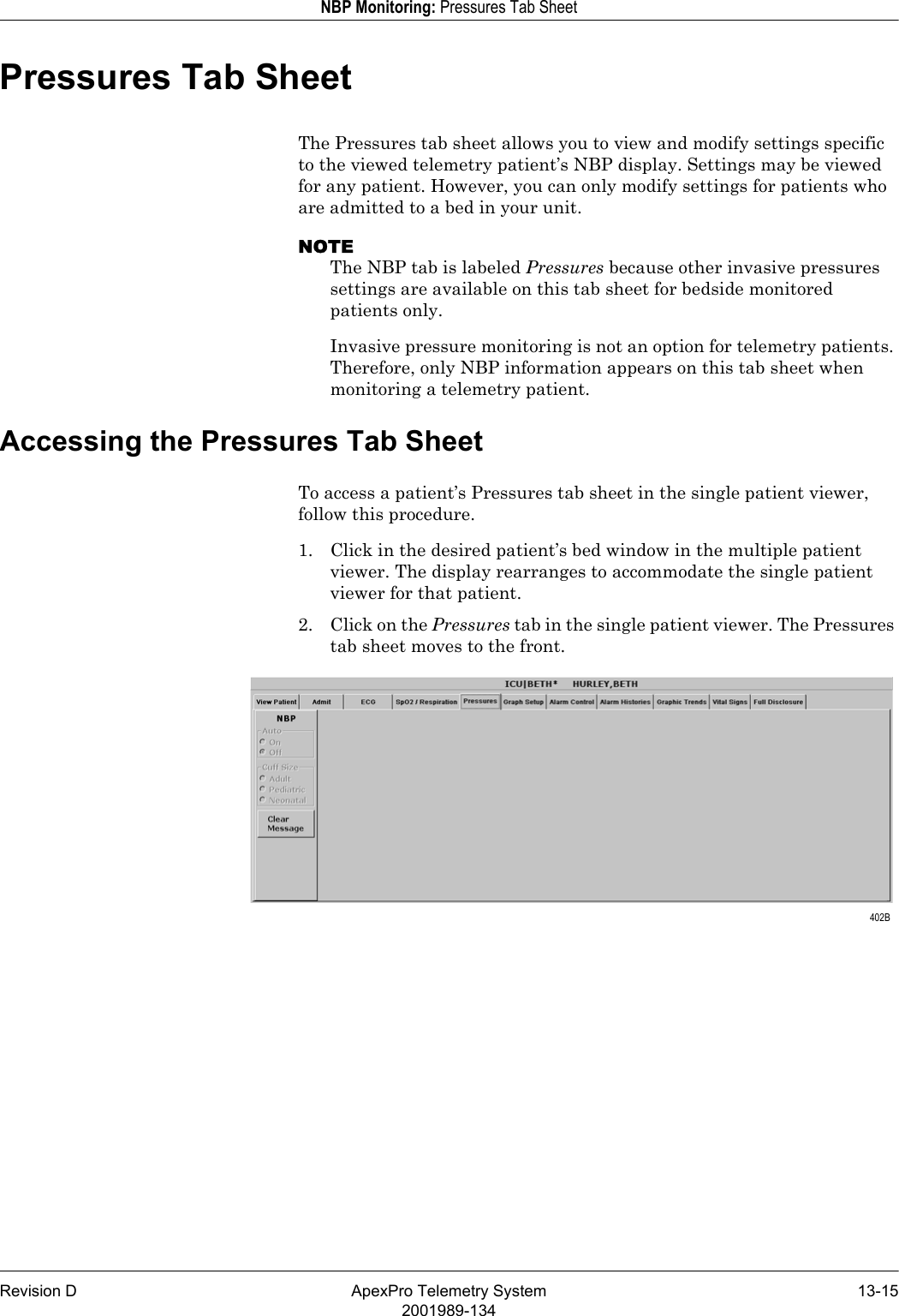
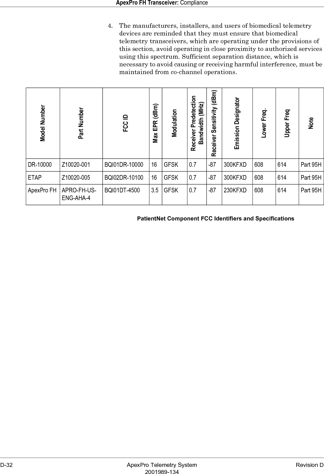
System Operators Manual Part 2

7-10 ApexPro Telemetry System Revision D2001989-134Admit/View a Patient: Discharge InstructionsClearing a Patient WindowTo clear discharged patient information from the window and bring up the Admit button, use the right-click menu.1. Use the RIGHT mouse button to click anywhere inside a discharged bed window. The right-click menu appears.2. Slide the mouse over the Select Care Unit, then Bed Number text, without pressing either mouse button. The text highlights, and a list of units on the network pops up.3. Without pressing either mouse button, slide the mouse pointer to None at the bottom of the list. Click the left mouse button on None.4. The popup list closes, and the patient window will now be empty, except for an Admit button.NOTEOn a locked bed, None is not an option. When beds are locked, you must discharge from the single patient viewer. 387A
Revision D ApexPro Telemetry System 7-112001989-134Admit/View a Patient: Move Telemetry PatientsMove Telemetry PatientsThis option allows you to move a telemetry patient to a new bed within the same care unit or to move Combo patients in and out of combo mode. The Move feature is located on the Admit tab sheet on the CIC Pro.To move a patient within the same care unit, follow this procedure:1. At the CIC Pro, select the bed window of the patient you wish to move.2. Click on the Admit tab to bring the tab sheet to the front.3. Select a new bed from the Location Bed: list.4. The Save button changes to Move, click Move to move the patient to the bed you selected from the bed list.5. Select Yes when the Patient Move dialog is displayed.Admit Patient Tab SheetA patient can not be moved to an unlocked bed if no bed slot is available. A dialog window appears indicating that the change is disallowed because the patient would be unmonitored.Moving Locked/Unlocked BedsThe following guide lines apply when moving locked and unlocked beds.A patient can be moved from an unlocked bed to another available unlocked bed.A patient can be moved from a locked bed to another available locked bed.A patient can be moved from an unlocked bed to an available locked bed. 126A
7-12 ApexPro Telemetry System Revision D2001989-134Admit/View a Patient: Viewing a PatientViewing a PatientWhen you wish to see detailed information about a patient’s status, you can use the View Patient tab in the single patient viewer.1. Click in the bed window of the patient you wish to view. The display rearranges to accommodate the single patient viewer at the bottom.2. Click on the View Patient tab to bring it to the front.The View Patient tab sheet shows all the information that normally appears in patient’s bed window in the multiple patient viewer, and also displays up to eight leads of ECG waveforms.There are two buttons in the View Patient tab sheet that can be used for telemetry patients. Their functions are described below.NOTEThe third button, View All ECG, is dimmed when viewing telemetry patients because all the ECG waveforms available for telemetry patients are normally displayed.SampleClicking on the Sample button records a sample of the patient’s real-time ECG data. This sample is then stored in alarm histories, and can be viewed in the Alarm Histories tab sheet under the title of Sample. For more information about viewing alarm histories, refer to Chapter 10, Patient Data, in this manual. 348D
Revision D ApexPro Telemetry System 7-132001989-134Admit/View a Patient: Viewing a PatientRelearnClicking on the Relearn button initiates a relearn of the patient’s ECG rhythm. The relearn takes only a few seconds. The patient’s heart rate reading will appear as Xs momentarily, and then be replaced by numerics once the relearn is complete.Use the relearn function whenever there has been a significant change in the patient’s normal rhythm.
7-14 ApexPro Telemetry System Revision D2001989-134Admit/View a Patient: Viewing Another PatientViewing Another PatientNOTEWhen viewing a patient from another unit, you cannot make any changes to the patient’s information or settings.Viewing in the Single Patient ViewerTo display the single patient viewer of a patient on the network who is not currently displayed on your CIC Pro, follow the steps below.1. Click on the View Other button in the Main Menu at the bottom of the CIC Pro display.2. The View Other Patient window appears. This window displays all the units currently available on your network.3. Click on the  next to the unit from which you wish to view a bed. A list of beds admitted to that unit appears below the unit name.NOTEIf a unit name has a  next to it but no bed list below it, there are no beds admitted into that unit.4. Click on the bed name you wish to view. The name is highlighted.5. Click on the OK button. The single patient viewer opens at the bottom of the display, showing the viewed patient’s data. 339B
Revision D ApexPro Telemetry System 7-152001989-134Admit/View a Patient: Viewing Another PatientViewing in the Multiple Patient ViewerWhen in the multiple patient viewer, you can replace the data in any unlocked bed window with the data from another patient on the network who is not currently displayed on your CIC Pro. NOTEThe data for the patient who was originally displayed in the bed window you select will not be visible on your CIC Pro once you use that patient’s bed window to view another patient.To view another patient in the multiple patient viewer, follow the steps below.1. Use the right mouse button to click anywhere inside a bed window. The right-click menu appears.NOTEYou must use the right mouse button to access the right-click menu.2. Slide the mouse over the Select Care Unit then Bed Number text, without pressing either mouse button. The text highlights, and a list of units on the network pops up. 349A
7-16 ApexPro Telemetry System Revision D2001989-134Admit/View a Patient: Viewing Another Patient3. Without pressing either mouse button, slide the mouse pointer to the unit name you wish to select a bed from. The unit name highlights, and a list of beds on that unit pops up.4. Without pressing either mouse button, slide the mouse pointer to the bed you wish to view. The bed name becomes highlighted.NOTEA check mark next to a bed name means that the bed is already being viewed at this CIC Pro.5. Once you have chosen the bed you wish to view, and its bed name is highlighted on this list, use the LEFT mouse button to click on the bed name. 6. The popup lists close, and the viewed patient’s data appears in the bed window. For more detailed patient information, use the left mouse button to click in the bed window. The single patient viewer will open at the bottom of the display, allowing you to view all the patient’s data. 338A
Revision D ApexPro Telemetry System 7-172001989-134Admit/View a Patient: Viewing Patients Through Alarm Condition IndicatorsViewing Patients Through Alarm Condition IndicatorsYou can open the single patient viewer for any patient in your care unit who is experiencing an alarm condition.When a patient experiences an alarm condition, a red button appears at the bottom of the CIC Pro display. The button contains the unit name and bed number, as well as the cause of alarm.NOTEUp to four of these red buttons display at one time, so only the four highest-level alarms are indicated in this way.To access the single patient viewer for the alarming patient, simply click on the red button at the bottom of the display. The display rearranges to accommodate the single patient viewer at the bottom of the display, and all the patient’s information will be available to you.
7-18 ApexPro Telemetry System Revision D2001989-134Admit/View a Patient: Viewing Patients Through Alarm Condition Indicators
Revision D ApexPro Telemetry System 8-12001989-1348Alarm Control
8-2 ApexPro Telemetry System Revision D2001989-134For your notes
Revision D ApexPro Telemetry System 8-32001989-134Alarm Control: Alarm StructureAlarm StructureThe alarm structure of the CIC Pro is divided into two classifications:Patient status alarmsSystem status alarmsWithin each classification there are levels that correlate to the severity of the condition that is causing the alarm. The levels and how the CIC Pro responds to each are described below.Patient Status AlarmsPatient status alarms are triggered by a patient condition that exceeds parameter limits, or by an arrhythmia condition. Patient status alarms provide the highest priority information.The levels within the patient status alarm category and how the CIC Pro responds to each are shown in the following chart. The chart begins with the most critical type of alarm (Crisis) and ends with the least critical type of alarm (Message).NOTEOnly arrhythmia alarm conditions are stored in alarm histories.Patient Status Alarms Chart 365A
8-4 ApexPro Telemetry System Revision D2001989-134Alarm Control: Alarm StructureColored Window BordersCrisis and Warning alarms are indicated with a large border around the individual patient’s bed window in the multiple patient viewer. This border flashes on and off several times when the alarm occurs before staying on. The color of the border indicates the severity of the alarm —red for a Crisis alarm and yellow for a Warning alarm. When the alarm is silenced, the colored border reverts to the black background.NOTEOnly Crisis and Warning alarms activate the colored border. Patients selected for single patient view have a white border in the multiple patient viewer.Automatic Alarm GraphsA graph prints automatically when a patient experiences a Crisis or Warning alarm. Arrhythmia alarm graphs run until the end of the alarm event. The printer prints the 10 seconds of data that occurred immediately before the event, and prints for the duration of the event. The printer stops printing when the patient returns to a normal rhythm. If a printer is not available at the time of the alarm event, a 20-second graph is saved. This saved graph will print when a printer becomes available.System Status AlarmsSystem status alarms are triggered by mechanical or electrical problems and are of lesser priority than patient status alarms. The levels within the system status alarm category and how the CIC Pro responds to each are shown in the following chart.System Status Alarms ChartSystem status alarms cannot, in most cases, be moved from one level to another. However, the CIC Pro allows you to set default alarm levels for the following system alarms: CHANGE BATTERY, OFF NETWORK, ARR SUSPEND, LEADS FAIL, PROBE OFF.The System Alarm Levels are configurable in Telemetry Alarm Control Defaults.TEXTTEXTTEXTTEXT366BFog-horn ToneWarning sounds continuouslyAdvisory sounds only onceWhite Text Displayed on Red BackgroundAlarm Level: Monitor Response:WARNINGADVISORYMESSAGE
Revision D ApexPro Telemetry System 8-52001989-134Alarm Control: Alarm Control TabAlarm Control TabParameter and arrhythmia alarm levels are, from most critical to least critical, Crisis, Warning, Advisory, and Message.Each alarm level elicits a specific response from the CIC Pro. The four alarm levels are configurable. This means that an alarm can be moved from one category to another if the default is not satisfactory to your situation. This is done in the Alarm Control tab sheet for the patient whose alarm settings you wish to adjust.NOTEASYSTOLE and VFIB/VTAC alarms cannot be moved from the Crisis level.Accessing the Alarm Control Tab1. Use the mouse to click in the window of the telemetry patient whose alarm settings you wish to view or change.2. The CIC Pro display rearranges as the single patient viewer opens at the bottom of the display. Click on the patient’s Alarm Control tab to bring the tab sheet to the front.The telemetry patient Alarm Control tab sheet is divided into three sections: Parameter Limits and Alarm Levels, Arrhythmia Alarm Levels, and Alarms On/Off. The options on this tab sheet are detailed on the following pages. 421C
8-6 ApexPro Telemetry System Revision D2001989-134Alarm Control: Alarm Control TabParameter Limits1. To change the individual patient’s settings for Parameter Limits and Alarm Levels, click in the Low or High field for the parameter you wish to change.NOTEThe alarm limits for some parameters cannot be changed. To indicate that they cannot be changed, the text in the Low and High fields for these parameters always appears dimmed.Once you click in the field, it is framed by a rectangle, and up and down arrow buttons appear in the field.NOTEAlarms generated by parameter limit violations are not stored in Alarm Histories.2. To increase or decrease the limit by 5, click on the up or down arrow button.To increase or decrease the limit in increments other than 5, use the keyboard to enter a new limit value.3. If you are finished making changes in the Alarm Control tab sheet, click on the Close button in the bottom right corner of the display to close the single patient viewer. 329A
Revision D ApexPro Telemetry System 8-72001989-134Alarm Control: Alarm Control TabParameter Alarm Levels1. Click in the Level field for the parameter whose alarm level is to be changed. A down arrow button appears in the field.2. Click on the down arrow button. A popup list of alarm level selections appears.NOTEAlarms are always sorted from top to bottom in highest to lowest priority. When you change a level, the list is re-sorted to reflect the change in alarm priority.3. Click on the desired alarm level to select it.4. If you are finished making changes in the Alarm Control tab sheet, click on the Close button in the bottom right corner of the display to close the single patient viewer. 331A
8-8 ApexPro Telemetry System Revision D2001989-134Alarm Control: Alarm Control TabArrhythmia Alarm Levels1. To change the Arrhythmia Alarm Levels, click in the Level field of the arrhythmia alarm you wish to change. A down arrow button appears in the field.NOTEThe Arrhythmia Alarm Levels for ASYSTOLE and VFIB/VTAC cannot be changed. Therefore, the text in the Level field for these alarms always appears dimmed.NOTEYou may need to use the scroll bar on the right side of the Arrhythmia Alarm Levels section in order to view the arrhythmia alarm that you wish to modify.NOTEAlarm levels are usually shown in black type. An alarm level shown in blue indicates that it is NOT the default level.2. Click on the down arrow button. A popup list of alarm level selections appears.3. Click on your choice to select it.4. If you are finished making changes in the Alarm Control tab sheet, click on the Close button in the bottom right corner of the display to close the single patient viewer. 325B
Revision D ApexPro Telemetry System 8-92001989-134Alarm Control: Alarm Control TabAlarms On/OffTo turn a telemetry patient’s alarms on or off, click on the appropriate radio button or on the text itself in the Alarms On/Off section of the Alarm Control tab.Selecting Off turns all alarms off until you turn them back on by selecting On.NOTERefer to the Alarm Pause Breakthrough section in this chapter for important information about turning alarms off.ON and OFF buttons 334B
8-10 ApexPro Telemetry System Revision D2001989-134Alarm Control: Alarm Control TabAlarm Off ReasonSelecting from a list of reasons, you can define why alarms have been turned off. This text is displayed in addition to the ALARMS OFF message in the patient’s window at the CIC Pro.The following are the options for alarms off reasons.Selecting OFF turns all alarms off until you turn them back on.Selecting any reason establishes an alarm pause state for 5 minutes in the presence of a valid waveform. After 5 minutes, alarms will reactivate if the patient is within range of the antenna system for 15 seconds or longer. If the patient remains out of antenna range, the alarm pause state will continue until the patient re-enters antenna range for 15 seconds or longer. NOTEThe patient must be in antenna range for the alarm pause state to cease.WARNINGAlarms do not sound, alarm histories are not stored, and alarm graphs do not print during an alarms off with reason condition.Alarms Off Reason Text Displayed At CIC Pro Text Printed On GraphOn (no text) (no text)Off ALARMS OFF OFFX-ray XRAY X-RAYShower SHOWER SHOWERSurgery SURGERY SURGERYPhysical therapy P.T. PHYSICAL THERAPYCardiac rehab CAR REHAB CARDIAC REHABGI Lab GI LAB GI LABOccupational therapy O.T. OCCUPATIONAL THERAPYOff unit OFF UNIT OFF UNTCath Lab CATH LAB CARDIAC CATH LAB
Revision D ApexPro Telemetry System 8-112001989-134Alarm Control: Alarm Control TabThe alarms off reason appears in the event trend for graphic trends.If the patient is in LEADS FAIL or NO TELEM and an alarms off reason is selected, the reason is displayed in the waveform window.NOTEAfter the patient has returned to antenna range and/or alarms have been turned back on, verify that the patient’s waveforms are displayed at the CIC Pro or bedside monitor.NOTERefer to the Alarm Pause Breakthrough section in this chapter for important alarm pause information.Enable Transmitter PauseThe Enable Transmitter Pause check box, when checked, allows alarms to be paused by pressing both ApexPro transmitter buttons simultaneously. To enable the transmitter pause option for a telemetry patient admitted to the CIC Pro, click in the Enable Transmitter Pause check box. A check mark appears in the check box.To disable the transmitter pause option, click in the Enable Transmitter Pause checkbox. The check mark is removed from the check box and the option is disabled.NOTEIf Off is selected for the Transmitter Alarm Pause option in the Telemetry Unit Defaults tab sheet, no check box appears on the tab.To make the Enable Transmitter Pause option active (check box available), either Enabled or Disabled must be selected for the Transmitter Alarm Pause option in the Telemetry Unit Defaults tab sheet. Refer to Chapter 6, Telemetry Setup, for information about setting the Transmitter Alarm Pause option.Alarm Pause Breakthrough Enabled/DisabledRefer to the Alarm Pause Breakthrough section in this chapter for information about this alarm pause breakthrough status message.
8-12 ApexPro Telemetry System Revision D2001989-134Alarm Control: Alarm Control TabRecalling Unit DefaultsTo recall the preset telemetry patient unit defaults for all options in the Alarm Control tab, simply click on the Recall Unit Defaults button on the bottom right side of the Alarm Control tab sheet. All data on the tab sheet will clear, and after a moment the preset unit defaults will appear.In addition, clicking on the Recall Unit Defaults button also restores the default graph locations and settings on the patient’s ECG tab sheet.Alarm HelpFor additional information about alarms, click on the Alarm Help button at the bottom right side of the Alarm Control tab sheet. An Alarm Help window appears.You can click on the buttons in this window to hear how each type of alarm sounds. When you are finished browsing the window, click on the Close Window button to close the window and return to the single patient viewer. 323A
Revision D ApexPro Telemetry System 8-132001989-134Alarm Control: Alarm Control TabPrinting Alarm SettingsA telemetry patient’s Alarm Control tab sheet can be printed, showing all current alarm settings and limits. Click on the Print button in the main menu to start a printout of the Alarm Control tab sheet.The Alarm Control tab sheet prints at the Print Window location. For more information about setting the Print Window location, refer to Chapter 9, Printing, in this manual.NOTEThe Alarm Control tab sheet must be the front tab of the single patient viewer in order to print it. Click on the Alarm Control tab to bring it to the front if necessary.Silencing AlarmsWARNINGDo NOT continuously press the silence key. You may inadvertently silence new patient alarms.You can silence the audible alarm tones in one of two ways:Use the mouse and click on the Silence Alarms button located on the display monitor’s screen.Press the Silence Alarms key located on the keyboard.Alarm Silence IconWhen an alarm is silenced, a visual indication (Alarm Icon) of the silenced alarm is displayed at the CIC Pro. The alarm silence icon is displayed in the ECG parameter window next to the ECG heart rate. The alarm silence icon remains on the display for one minute unless a new alarm occurs.NOTEIf you are monitoring telemetry patients, new alarms of equal or greater priority level break the alarm silence condition. 427A 426AAlarm Silence Icon
8-14 ApexPro Telemetry System Revision D2001989-134Alarm Control: Alarm Pause BreakthroughAlarm Pause BreakthroughThe alarm pause breakthrough feature allows any crisis level alarm to “break through” (interrupt) an alarm pause and sound at the CIC Pro.In other words, when this feature is turned on in the Telemetry Unit Defaults tab sheet, Crisis level alarms will sound at the CIC Pro, even if an alarm pause is in effect.NOTEThe Alarm Pause Breakthrough feature defaults to Always On. It must be set to Always Off in the Telemetry Unit Defaults tab sheet BEFORE admitting a telemetry patient if you do not wish to have Crisis level alarms break through alarm pauses.This feature cannot be set on an individual patient basis. It is either on or off for all telemetry patients admitted to the CIC Pro. A status message on each patient’s Alarm Control tab sheet indicates whether it is enabled (on) or disabled (off). The chart below illustrates the function of the alarm pause breakthrough feature during the various alarm states.After a Crisis level alarm has broken through an alarm pause, the telemetry system does NOT return to an alarm pause state. All alarms at any alarm level will sound at the CIC Pro.Alarm State Alarm Pause Breakthrough FunctionAlarms on No alarm pause breakthrough; all alarms are on.Alarms off No alarm pause breakthrough; all alarms are off.Alarm off reason (X-ray, shower, etc.)Alarms are paused; Crisis level alarms will break through the alarm off reason if the patient is in antenna range.Alarms paused from the ApexPro transmitterAlarms are paused; Crisis level alarms will break through the alarm pause.
Revision D ApexPro Telemetry System 8-152001989-134Alarm Control: Alarm Pause BreakthroughIf you wish to continue pausing alarms after an alarm pause breakthrough occurs, you must re-initiate the alarm pause:1. To re-initiate an alarms off with reason condition, select the alarms off reason in the telemetry patient’s Alarm Control tab sheet.2. To re-initiate an alarm pause from the ApexPro transmitter, press both transmitter buttons simultaneously twice.NOTEThe transmitter buttons must be pressed once to “end” the alarm pause at the transmitter, then a second time to start a new alarm pause at the transmitter (see below).The Pause Alarm LED on the ApexPro transmitter continues to flash after an alarm pause breakthrough occurs. This is because there is no communication from the CIC Pro back to the ApexPro transmitter to indicate that the alarm pause has ended. After an alarm pause breakthrough occurs, you can turn off the flashing Pause Alarm LED by pressing both transmitter buttons simultaneously.
8-16 ApexPro Telemetry System Revision D2001989-134Alarm Control: Unit Default Settings for AlarmsUnit Default Settings for AlarmsTelemetry Alarm Control DefaultsYou can set Telemetry Unit Defaults for parameter limits and alarm levels, as well as for arrhythmia alarm levels. These defaults are in effect for all telemetry patients admitted to your unit, unless they are modified in an individual patient’s Alarm Control tab sheet (for more information, see the Alarm Control Tab section in this chapter).To set telemetry alarm control defaults, follow the steps below:1. Click on the Setup CIC button at the bottom of the CIC Pro display. A set of tabs appears.2. Click on the Service Password tab to bring it to the front. 318B
Revision D ApexPro Telemetry System 8-172001989-134Alarm Control: Unit Default Settings for Alarms3. Use the keyboard to enter the service password, then click the Apply button. The Current Permission entry changes from User to Service.CAUTIONThe service mode is intended for use only by qualified personnel with training and experience in its use. The consequences of misuse include loss of patient data, corruption of the CIC Pro operating system software, or disruption of the entire Unity network.4. Click on the Telemetry Alarm Control Defaults tab to bring it to the front. 319D
8-18 ApexPro Telemetry System Revision D2001989-134Alarm Control: Unit Default Settings for AlarmsParameter Limits5. To change the unit defaults for Parameter Limits and Alarm Levels, use the mouse to click in the Low or High field for the parameter you wish to edit. The field is framed by a rectangle, and up and down arrow buttons appear in the field.6. To increase or decrease the limit by 5, click on the up or down arrow button.To increase or decrease the limit in increments other than 5, use the keyboard to enter a new limit value.7. Once you have set the desired limit, click on the Apply button for the changes to take effect.NOTEIf you make only one change, you do not need to click on the Apply button. The change will take effect automatically, and the Apply button will appear dimmed.8. If you are finished making changes to the Telemetry Alarm Control Defaults tab sheet, click the OK button. 329A
Revision D ApexPro Telemetry System 8-192001989-134Alarm Control: Unit Default Settings for AlarmsParameter Alarm LevelsTo make a change in the telemetry unit default alarm level for a parameter, first access the Telemetry Alarm Control Defaults tab as described in the Telemetry Alarm Control Defaults section in this chapter. Then follow the procedure below.1. In Telemetry Alarm Control Defaults tab, use the mouse to click in the Level field of the parameter for which the alarm level is to be changed. A down arrow button appears in the field.2. Click on the down arrow button. A popup list of alarm level selections appears.3. Click on the desired alarm level to select it.4. Once you have set the desired level, click the Apply button for the changes to take effect.5. If you are finished making changes to the Telemetry Alarm Control Defaults tab sheet, click the OK button. 331A
8-20 ApexPro Telemetry System Revision D2001989-134Alarm Control: Unit Default Settings for AlarmsArrhythmia Alarm LevelsTo make a change in the telemetry unit default alarm level for arrhythmia alarms, first access the Telemetry Alarm Control Defaults tab as described in the Telemetry Alarm Control Defaults section in this chapter. Then follow the procedure below.1. In the Telemetry Alarm Control Defaults tab, the arrhythmia alarm levels for which unit defaults can be set appears on the right side of the window:2. Click in the Level field of the arrhythmia alarm you wish to modify. A down arrow button appears in the field.NOTEThe arrhythmia alarm levels for ASYSTOLE and VFIB/VTAC cannot be changed. Therefore, the text in the Level field for these alarms always appears dimmed.3. Click on the down arrow button. A popup list of alarm level selections appears.4. Click on your choice to select it.5. Once you have set the desired level, click the Apply button for the changes to take effect.If you are finished making changes to the Telemetry Alarm Control Defaults tab sheet, click the OK button. 333C
Revision D ApexPro Telemetry System 8-212001989-134Alarm Control: Unit Default Settings for AlarmsSystem Alarm LevelsWARNINGADJUSTING SYSTEM ALARM LEVELS — The LEADS FAIL alarm indicates that one or more electrodes are not connected to the patient and, as a result, there is loss of all waveforms and arrhythmia analysis. The ARR SUSPEND alarm indicates that arrhythmia conditions are not being detected and therefore alarms associated with arrhythmias will not occur. The LEADS FAIL and ARR SUSPEND alarms should be adjusted to a lower priority level only by experienced qualified personnel and with great caution. Adjusting these alarms to a lower priority level may result in reduced awareness of conditions that indicate the loss of patient monitoring. To make a change in the telemetry unit default alarm level for system alarms, first access the Telemetry Alarm Control Defaults tab as described in the Telemetry Alarm Control Defaults section in this chapter. Then follow the procedure below.1. In the Telemetry Alarm Control Defaults tab, the system alarm levels for which unit defaults can be set appears on the right side of the window:2. Click in the Level field of the system alarm you wish to modify. A down arrow button appears in the field.3. Click on the down arrow button. A popup list of alarm level selections appears.4. Click on your choice to select it.5. Once you have set the desired level, click the Apply button for the changes to take effect.If you are finished making changes to the Telemetry Alarm Control Defaults tab sheet, click the OK button. 430A
8-22 ApexPro Telemetry System Revision D2001989-134Alarm Control: Unit Default Settings for AlarmsFor your notes
Revision D ApexPro Telemetry System 9-12001989-1349Printing
9-2 ApexPro Telemetry System Revision D2001989-134For your notes
Revision D ApexPro Telemetry System 9-32001989-134Printing: Initiating a Manual GraphInitiating a Manual GraphIf you click on a patient’s ECG parameter window, a continuous graph is initiated for the patient. Clicking on the ECG parameter window again will stop the graph.The PRN 50 digital writer and the Direct Digital Writers (DDW) print patient data (generally referred to as a graph or graph strip). Data can also be printed on a laser printer. The waveforms graphed and graph speed are controlled in the individual patient’s Graph Setup tab sheet. Unit defaults for telemetry patients can be set in the CIC Defaults tab sheet and the Telemetry Unit Defaults tab sheet. Refer to Chapter 6, Telemetry Setup, for more information on setting telemetry unit defaults.Automatic Alarm GraphsA graph prints automatically when a patient experiences a Crisis or Warning alarm condition. Arrhythmia alarm graphs run until the end of the alarm event. The printer prints up to 10 seconds of data that occurred immediately before the event, and prints for the duration of the event. The printer stops printing when the patient returns to a normal rhythm. If a printer is not available at the time of the alarm event, a 20-second graph is saved. This saved graph will print when a printer becomes available.
9-4 ApexPro Telemetry System Revision D2001989-134Printing: Initiating a Manual GraphTransmitter Initiated Graphs (Manual Graphs) When the Graph button on the ApexPro transmitter is pressed, a 20-second graph strip is printed at a speed of 25 millimeters per second.When an IMPACT.wf paging system (version II or later) is also available in the same care unit, pressing the Graph button enables the View on Demand feature (also called the Apex Graph Button Push feature). The IMPACT.wf server generates a manually initiated sample page or snapshot of the patient’s ECG waveform and any other enabled/monitored non-arrhythmia parameters. When you press the Graph button on the ApexPro transmitter, it generates both an IMPACT.wf update page as well as a standard ECG waveform graph at the CIC Pro. The IMPACT.wf page is labeled “Sample” when this data is displayed on the IMPACT.wf receiver and stored in history. Additionally, all pagers assigned to the patient receive a page.Graph button 309B
Revision D ApexPro Telemetry System 9-52001989-134Printing: Initiating a Manual GraphGraph MessagesOne of the following messages is displayed on the CIC Pro screen during graphing:GRAPH ALARM—An alarm graph was initiated and is running.GRAPH MANUAL—A manual graph was requested and is running.GRAPH TTX—The Graph button on the transmitter was pressed and a 20-second graph strip is running.PRINTING—A non-real time graph is currently being printed.SAVING—An alarm or a manual graph has been requested but the writer is in use; the writer door is open; or the writer is out of paper. The graph is being saved until the writer is available. (The most recent 20-second alarm or manual graph will be saved.)
9-6 ApexPro Telemetry System Revision D2001989-134Printing: Graph All PatientsGraph All PatientsClicking on the Print button at the bottom of the CIC Pro display sends a Graph All Patients request to all beds displayed on the CIC Pro, initiating a 10-second graph for each admitted telemetry patient. When this option is selected for telemetry patients, graph requests always print at a speed of 25 millimeters per second.NOTEThis Graph All Patients function is only available when the single patient viewer is closed. If a single patient viewer is open, selecting Print from the main menu initiates a printout of whichever tab sheet is in front.The print process stops automatically. If the Graph Stop control key is pressed on the external DDW, the current patient’s graph stops and the writer begins to print a 10-second graph for the next patient.If a patient’s data is currently printing or is being saved to print when a Graph All Patients request is initiated, this patient’s data will not be included in the Graph All Patients graph. This patient’s data will print independently of the Graph All Patients graph. Clicking on the ECG parameter window for a patient whose data is saving will cancel the Graph All Patients request for that patient.If, while a Graph All Patients request is in progress, an arrhythmia alarm occurs for a patient, the alarm data will replace the data that was saved for the Graph All Patients request. The alarm data will then appear on the graph printout.If, while a Graph All Patients request is running, a telemetry patient initiates a graph from his or her telemetry transmitter, the saved data for the Graph All Patients graph will be replaced by data from the patient’s telemetry transmitter. The data from the telemetry transmitter will then appear on the graph printout.
Revision D ApexPro Telemetry System 9-72001989-134Printing: Graph All PatientsInitiating a Graph All Patients RequestTo initiate a Graph All Patients request, follow these steps.1. Click on the Print button at the bottom of the CIC Pro display. The Graph All Patients window opens.2. Click on Limits or Waveforms.Selecting Limits graphs all patient limits.Selecting Waveforms graphs all patient waveforms.3. Click on the OK button to complete the Graph All Patients request. 378A
9-8 ApexPro Telemetry System Revision D2001989-134Printing: Graph Location SettingsGraph Location SettingsGraphs print at the graph locations specified in the patient’s Graph Setup tab sheet. Upon admission of a patient, these locations are set from the unit defaults, but they can be modified if desired. Following are guidelines for Graph Location:Manual graphs and print window requests print at the CIC Pro where the graph was requested, provided that CIC Pro has the same type of writer or printer as the graph location set for the patient for that type of graph. If the CIC Pro where the graph was requested does not have the same type of writer or printer, the graph prints to the patient’s specified graph location.If a telemetry patient is duplicated on another CIC Pro, alarm graphs continue to print at the clinical information center where the patient was first displayed (admitted).If using the move feature, the patient’s graph settings are retained as set on the original clinical information center. If a patient displays on a clinical information center that is not connected to a printer, the graph settings default to the graph location designated in the unit defaults. See “Telemetry Unit Defaults” on page 6-7.If no graph location is defined for a telemetry patient at the time of admission, the message “Saving” displays. Graphs are not sent to printers outside the unit.For more information on designating graph locations, refer to the Graph Location Controls section in this chapter.
Revision D ApexPro Telemetry System 9-92001989-134Printing: Stopping a GraphStopping a GraphTo stop a graph request that has been sent to an external writer, press its Graph Stop control key. This stops any graph already in process. If this key is pressed when no graph is in process, it advances the paper in the writer.A manual graph may also be stopped by clicking on the patient's ECG parameter window. An Automatic Alarm Graph may be stopped by clicking on the patient's ECG window twice, once to change the graph to a manual graph, and then a second time to stop the graph.NOTEBecause the CIC Pro can communicate with many laser printers, the specific procedure for stopping a graph sent to a laser printer is not documented in this manual. Refer to the laser printer manufacturer’s instructions.
9-10 ApexPro Telemetry System Revision D2001989-134Printing: Graph Paper Out IndicatorGraph Paper Out IndicatorWhen there is no graph paper in the writer (or the door is open), the message Graph Paper Out/Door Open is displayed at the top of the screen.When printing to a laser printer, a similar status message is displayed if the printer is unable to print.NOTEBecause the CIC Pro can communicate with many laser printers, specific status messages are not documented in this manual.
Revision D ApexPro Telemetry System 9-112001989-134Printing: Graph Setup Tab SheetGraph Setup Tab SheetThe Graph Setup tab sheet allows you to define the waveforms to be graphed, change the graph location and speed, and turn the telemetry transmitter graph on and off. NOTEChanges made in the Graph Setup tab sheet affect only the patient currently being viewed. To make changes to graph information for all telemetry patients in the unit, you must use the CIC Setup and the Telemetry Unit Defaults tab sheets (refer to Chapter 6, Telemetry Setup, in this manual).To view a patient’s Graph Setup tab sheet, follow these steps.1. Click on the desired patient’s information in the multiple patient viewer. The single patient viewer for that patient opens.2. Click on the Graph Setup tab. The Graph Setup tab sheet moves to the front. 357C
9-12 ApexPro Telemetry System Revision D2001989-134Printing: Graph Setup Tab SheetGraph Waveforms ControlsThe Graph Waveforms controls allow you designate which waveforms should print in which positions on a patient’s graph printout.ECG 1 Control1. Click in the ECG 1 field. A down arrow button is displayed next to the waveform currently in the ECG 1 position.2. Click on the down arrow to display a list of available ECG waveforms.3. Click on the desired ECG waveform. The ECG 1 menu closes, with the selected ECG waveform name remaining visible.NOTEThis action also changes displayed waveforms in the multiple patient viewer.Waveform 2, Waveform 3, and Waveform 41. Click in the field for the waveform you wish to designate. A down arrow icon is displayed next to the waveform currently in the Waveform X position.NOTEWaveform X refers to Waveform 2, Waveform 3, or Waveform 4, depending on which field you are in.2. Click on the down arrow to display a list of available waveforms.3. Click on the desired waveform. The waveforms menu closes, with the selected waveform name remaining visible.
Revision D ApexPro Telemetry System 9-132001989-134Printing: Graph Setup Tab SheetGraph Location ControlsThe Graph Location controls allow you to set the print destinations for manual, alarm, and print window graphs. Manual Graph LocationTo designate where manual graph requests will print, follow these steps. 1. Click in the Manual field. A down arrow icon is displayed next to the printer currently designated for printing manual graphs.2. Click on the down arrow to display a list of available printers.3. Click on the desired printer. The printers menu closes, with the selected printer name remaining visible. Alarm Graph LocationTo designate where alarm graphs will print, follow these steps. 1. Click in the Alarm field. A down arrow icon is displayed next to the printer currently designated for printing alarm graphs.2. Click on the down arrow to display a list of available printers.3. Click on the desired printer. The printers menu closes, with the selected printer name remaining visible.Print Window LocationTo designate where print window requests will print, follow these steps. 1. Click in the Print Window field. A down arrow icon is displayed next to the printer currently designated for printing alarm graphs.2. Click on the down arrow to display a list of available printers.3. Click on the desired printer. The printers menu closes, with the selected printer name remaining visible.
9-14 ApexPro Telemetry System Revision D2001989-134Printing: Graph Setup Tab SheetEnable Transmitter GraphThe Enable Transmitter Graph option allows you to turn off/on the transmitter graph function for telemetry patients. When this option is enabled, a telemetry patient can initiate a graph by pressing the Graph button on the ApexPro transmitter. When this option is disabled, no graph can be initiated. To enable or disable this option, follow this procedure:1. To enable the transmitter graph option, point and click with the mouse to place a check mark in the Enable Transmitter Graph check box.2. To disable the transmitter graph option, point and click with the mouse to remove the check mark in the Enable Transmitter Graph check box.Alarm Graphs Enabled/DisabledThis message line indicates whether the graph on alarm feature is on (Alarm Graph ENABLED) or off (Alarm Graph DISABLED). This feature cannot be set on an individual patient basis. Use the Alarm Graph option in the Telemetry Unit Defaults tab sheet to set it for all patients admitted to the CIC Pro.Enable Transmitter Graph Check Box 357C
Revision D ApexPro Telemetry System 9-152001989-134Printing: Graph Setup Tab SheetGraph Speed ControlsThe graph Speed controls allow you to adjust the speed at which a graph prints (mm/s). Simply click on the desired speed. 382A
9-16 ApexPro Telemetry System Revision D2001989-134Printing: Laser PrinterLaser PrinterA laser printer can be connected to the back of the CIC Pro. (Refer to the service manual for more information on printer connections.) The CIC Pro must be formatted for a laser printer upon installation in order for a laser printer to function with it. Refer to the service manual for the CIC Pro for more information.Printing to a laser printer for a telemetry patient may be configured on an individual basis or set up as a unit default. For more information, refer to the Graph Setup Tab Sheet section in this chapter, and to Chapter 6, Telemetry Setup, in this manual.You can send all information that can currently be formatted for a writer to a laser printer at the CIC Pro.To graph information to a laser printer at the CIC Pro, select the laser printer under the Graph Location controls in the Graph Setup tab sheet.
Revision D ApexPro Telemetry System 10-12001989-13410 Patient Data
10-2 ApexPro Telemetry System Revision D2001989-134For your notes
Revision D ApexPro Telemetry System 10-32001989-134Patient Data: IntroductionIntroductionFor the purposes of this manual, patient data consists of the information presented within these tab sheets:Alarm HistoriesGraphic TrendsVital SignsFull DisclosureOnce a patient is admitted to the CIC Pro, a history of the patient’s vital signs is continually collected. The most recent 24 hours of data can be viewed in a tabular format (vital signs) or in a graphic format (graphic trends). Every non-episodic parameter is sampled every two seconds. A median value is determined, and that value is stored for display at one-minute resolution. Episodic parameters (NBP, etc.) are stored every time one occurs. If more than one episodic event occurred during the same minute, the more recent event will overwrite the earlier one.Alarm histories for arrhythmia events are recorded and stored, up to a maximum of 100 events (36 events in Combo mode) per patient.When full disclosure is turned on, complete ECG data for each patient is recorded and stored for viewing.You cannot change any patient data values, but you can use the controls to view all the data collected.Patient data can be viewed in varying time scales and can be printed to a connected laser printer or a writer.
10-4 ApexPro Telemetry System Revision D2001989-134Patient Data: Alarm HistoriesAlarm HistoriesA patient’s arrhythmia events are stored in Alarm Histories, and can be reviewed, printed, and deleted at the CIC Pro. To access a patient’s Alarm Histories tab sheet, follow the instructions below.1. Click in the bed window of the patient whose Alarm Histories you wish to view. The CIC Pro display rearranges to accommodate the single patient viewer at the bottom of the display.2. In the single patient viewer, click on the Alarm Histories tab, bringing it to the front.The Alarm Histories tab sheet contains an event directory (a list of arrhythmia events recorded) for the patient, and an event window for viewing individual events. It also contains several buttons, which control the functions available in Alarm Histories. These functions are described in this chapter.Event DirectoryEvent Window 324D
Revision D ApexPro Telemetry System 10-52001989-134Patient Data: Alarm HistoriesEvent DirectoryAn event directory appears on the left side of the Alarm Histories tab. This directory is a list of all arrhythmia events that have occurred for this particular patient. A maximum of 100 events is stored for each patient (36 events in the Combo monitoring mode). Following are the numbers for each type of event that can be stored.20 ST Alarm Histories1 ST Reference10 Sample Events (user stored)100 Arrhythmia EventsAfter 100 events have been stored, the oldest event is deleted to make room for any new event that occurs.Approximately 10 events can be seen in the event directory at one time. There are two ways to access events that are not currently visible in the event directory. You can use the mouse and the scroll bar on the right side of the event directory to scroll up and down through all the events, or you can use the Scan Newer Events and/or Scan Older Events buttons. How to use these two buttons is discussed later in this chapter.Event WindowThe event window appears on the right side of the Alarm Histories tab sheet. The event shown in the event window corresponds to the event that is highlighted in the event directory. The date, time, and name of the event are shown in the event window header.The event window displays 10 seconds of the patient’s ECG waveform that was recorded when the event occurred. It displays up to three leads that were being monitored at the time the event occurred. For an ST event, the alarm ST event is displayed, along with a superimposed ST template for reference purposes.To print an event shown in the event window, use the mouse to click on the Print button in the Main Menu at the bottom of the CIC Pro. One event is printed per page.
10-6 ApexPro Telemetry System Revision D2001989-134Patient Data: Alarm HistoriesAlarm Histories ButtonsThere are nine buttons that perform various functions in the Alarm Histories tab. They are described below.Data SourceThis option allows the user to select the specific data source from which historical patient data can be retrieved (option not  shown on figure). Refer to “Data Source” on page 10-16 for additional information.Scan Newer EventsClick on the Scan Newer Events button to move through all events in the event directory that are newer than the event that is currently highlighted. If there are no events newer than the highlighted event, this button is dimmed and does not function. This button changes to STOP when a scan is in process. To stop a scan, click on the button again. While the scan is in progress, you can also select Scan Older Events to reverse the scanning direction.Scan Older EventsClick on the Scan Older Events button to move through all events in the event directory that are older than the event that is currently highlighted. If there are no events older than the highlighted event, this button is dimmed and does not function. This button changes to STOP when a scan is in process. To stop a scan, click on the button again. While the scan is in progress, you can also select Scan Newer Events to reverse the scanning direction.Print DirectoryClick on the Print Directory button to print a list of all events currently stored in the event directory. The list prints at the Print Window graph default location.View Newer EventClick on the View Newer Event button to view the next newer event waveforms, if any. If there are no events newer than the highlighted event, this button is dimmed and does not function.
Revision D ApexPro Telemetry System 10-72001989-134Patient Data: Alarm HistoriesView Older EventClick on the View Older Event button to view the next older event waveforms, if any. If there are no events older than the highlighted event, this button is dimmed and does not function.Delete EventClick on the Delete Event button to delete the event that is currently highlighted in the event directory. This cannot be undone.If more than one event is highlighted (using Shift or Ctrl and the mouse), a message appears when you press the Delete Event button, asking if you are sure you wish to delete the events. Click on Ok to continue the delete.Learn AsThe Learn As button is inactive for telemetry patients and appears dimmed.RelearnSelect the Relearn button to initiate a relearn procedure. A relearn will clear the patient’s waveforms and templates, and learn the patient’s current rhythm as the dominant, “normal” rhythm. Relearn is useful when you have changed a patient’s electrodes or leadwires, or when it appears that false alarm calls are being made by the arrhythmia program. The relearn takes only a few seconds.CaliperSelect the Caliper button to perform caliper measurements on the ECG waveform. When selected, the Caliper window opens displaying default ECG waveform and Calipers which allow you to measure time intervals for the following waveform measurements: PR, QRS, QT, R-R, and ST.
10-8 ApexPro Telemetry System Revision D2001989-134Patient Data: Graphic TrendsGraphic TrendsTo view a patient’s graphic trends, follow these steps.1. Click on the desired patient’s bed window in the multiple patient viewer. The single patient viewer for that patient opens.2. Click on the Graphic Trends tab in the single patient viewer. The Graphic Trends tab sheet moves to the front.Trend Directory WindowUp to three graphic trend plots can be displayed in the Graphic Trends window at one time. You can select from preset groupings of trends or individual trends.To select the trends for display in the Graphic Trends window, click on a preset trend grouping or individual trends (up to three). When selected, a check appears in the box to the left of the label.Trend Directory WindowGraphic Trends Window Graphic Trend LabelsNumeric Values at the CursorTime Resolution MenuScans Older/Newer Graphic TrendsCursor 384CIndicates PDS Information is Being DisplayedScales Trends
Revision D ApexPro Telemetry System 10-92001989-134Patient Data: Graphic TrendsCursorOne-minute median values can be accessed through the use of a cursor at the CIC Pro.The default cursor location is at the current time when entering the Graphic Trends tab sheet.You can move the cursor to any median value and review the actual numeric data.The cursor is not printed with the graphic trend data. 384CCursorTime and Date Corresponding to Cursor PositionArrow Keys Move CursorNumeric Values at the Cursor
10-10 ApexPro Telemetry System Revision D2001989-134Patient Data: Graphic TrendsTime Resolution MenuIn the Graphic Trends tab sheet, you can define the amount of trend data (resolution) to display in the trend window. This is done with the popup menu located to the right of the time and date.1. Click on the down arrow to display the time options.2. Click on the desired time resolution. The time resolution menu closes, with the selected resolution remaining visible. The selected time resolution is also reflected immediately in the Graphic Trends window.Graphic Trends ButtonsThere are six buttons that perform various functions in the Graphic Trends tab. The function of each button is described below.Data SourceThis option allows the user to select the specific data source from which historical patient data can be retrieved (option not  shown on figure). Refer to “Data Source” on page 10-16 for additional information.Deselect AllClick on the Deselect All button to clear all trends from the Graphic Trends window. Selecting this option also removes any checks from the Trend Directory window. 385A
Revision D ApexPro Telemetry System 10-112001989-134Patient Data: Graphic TrendsScan OlderClick on the Scan Older button to initiate a scan of older trend data. When clicked, the scan begins and older trend data scrolls across the display. While the scan is in progress, you can select Scan Newer to reverse the scanning direction.This button changes to STOP when a scan is in process. Click on the STOP button to stop a scan in process. When the oldest event is displayed, the scan automatically stops, and the label on this button will be dimmed.Scan NewerClick on the Scan Newer button to initiate a scan of newer trend data. When clicked, the scan begins and newer trend data scrolls across the display. While the scan is in progress, you can select Scan Older to reverse the scanning direction.This button changes to STOP when a scan is in process. Click on the STOP button to stop a scan in process. When the most recent event is displayed, the scan automatically stops, and the label on this button will be dimmed.Arrow KeysThe arrow buttons on the Graphic Trends tab sheet allow you to move the cursor one minute to the left or right.Using the left arrow moves the cursor one minute in the “older” direction. When the oldest (least recent) event is displayed, the left arrow is dimmed.Using the right arrow moves the cursor one minute in the “newer” direction. When the newest (most recent) event is displayed, the right arrow is dimmed.040A
10-12 ApexPro Telemetry System Revision D2001989-134Patient Data: Graphic TrendsScalable Trends KeyThe Scalable Trends keys allow you to adjust the graphic trend plots. Selecting this key will scale the trend up or down in preset increments. For example, the preset scales for HR are: 50–1500–100100–2000–250PDS IconThe PDS (Patient Data Server) icon indicates that information has been archived to the PDS server and is available to be viewed on the Graphic Trends tab sheet. If this icon does not appear in the lower right corner of the Graphic Trends tab sheet, it could mean two things:The PDS server is not available for retrieving patient information, orNo PDS information has been archived to the PDS server for this patient.Printing Graphic TrendsTrends can be printed using the same time scale as the display. To print a graphic trend, click on the Print button at the bottom of the CIC Pro display.Graphic trend printouts for telemetry patients can be printed to a laser printer or to a writer. Graphic trends print to the Print Window default printer location.431A087A
Revision D ApexPro Telemetry System 10-132001989-134Patient Data: Vital SignsVital SignsTo view a patient’s vital signs, follow these steps.1. Click in the desired patient’s bed window in the multiple patient viewer. The single patient viewer for that patient opens.2. Click on the Vital Signs tab in the single patient viewer. The Vital Signs tab sheet moves to the front. The Vital Signs tab sheet displays periodic and episodic trend data in tabular, or spreadsheet, form.NOTEWhen a telemetry patient’s vital signs are printed to a Direct Digital Writer, the anchor column (the column closest to the time interval selected) and four additional columns print, based on the time interval selected.Printed data may be delayed by one minute from the displayed data due to time of request and update of trend files.Data SourceThis option allows the user to select the specific data source from which historical patient data can be retrieved (option not  shown on figure). Refer to “Data Source” on page 10-16 for additional information.Sort Mode Menu Increment Menu 422A
10-14 ApexPro Telemetry System Revision D2001989-134Patient Data: Vital SignsSort ModeThe Sort Mode popup menu provides options for sorting the way vital signs data is viewed. If the telemetry patient is being monitored for NBP, the sort options are All Data and NBP. If the patient is not being monitored for NBP, the only option available is All Data. All other sort options appear dimmed.IncrementIn the Vital Signs tab sheet, you can define the amount of data (resolution) to display in the Vital Signs window. This is done with the Increment popup menu.1. Click on the down arrow to display all of the Increment options.2. Click on the desired increment. The Increment menu closes, with the selected increment remaining visible. The selected increment is also reflected immediately in the Vital Signs window. 360A 386A
Revision D ApexPro Telemetry System 10-152001989-134Patient Data: Vital SignsScroll BarsIf all of the Vital Signs data does not fit into the available display space, use the scroll bars to navigate among columns and rows of data. For more information on using scroll bars, refer to the CIC Pro Clinical Information Center Operator’s Manual.Printing Vital SignsDisplayed trends can be printed using the same time scale as the display. To print a set of vital signs, click on the Print button at the bottom of the CIC Pro display. Trends for telemetry patients can be printed to a laser printer or to a writer. Printing to a writer can only be done in Combo monitoring mode and must be done from a bedside monitor.
10-16 ApexPro Telemetry System Revision D2001989-134Patient Data: Data SourceData SourceThe Data Source option allows the user to select the specific data source from which historical patient data (Alarm Histories, Graphic Trends, and Vital Signs) can be retrieved. The Data Source option is only available when PDS is Enabled (refer to “Telemetry Unit Defaults” on page 6-7). The Data Source option is labeled Data Source and exists on the left side of the screen, between the Multi-patient viewer and the Single view window. Next to this label are two radio buttons that indicate the possible data sources:Bedside — This can be either a telemetry or a hardwire bedside. The amount of historical data is limited to the specific data source. For most hardwire bedsides, there is a limit of around 32 history events and 24 hours of trend data.PDS — This server gathers and stores trend and history events from hardwire bedsides and telemetry transmitters (refer to the compatibility list in the Unity Network Patient Data Server (PDS) Operator’s Manual. Patient data recorded during previous (72 hours) bedside or telemetry device admissions can be viewed as a single “patient centric” session. Up to 72 hours of trend data and 500 history events can be stored for a single patient. The radio button for PDS data source will be disabled in the Alarm Histories, Graphic Trends and Vital Signs tab sheets for a bedside that is not being monitored by PDS.Once the user makes a data source selection for a specific patient, the setting remains in effect, allowing the user to interact with the data from the selected data source. Data for printing will be consistent with the currently selected data source. Selecting a different patient in the multi-viewer or re-selecting the same patient will automatically change the data source to be the bedside device.NOTEIf the operator is on a tab sheet other than Alarm Histories, Graphic Trends, or Vital Signs, no selection of the data source is possible. For any application where information needs to be retrieved, such as patient name, patient ID and alarm control information, the bedside device will be used.Data Source:   ~Bedside {  PDS
Revision D ApexPro Telemetry System 10-172001989-134Patient Data: Time FocusTime FocusThe CIC Pro has a feature called time focus. When you are viewing one of the four types of patient data (alarm histories, vital signs, graphic trends, or full disclosure), time focus allows you to view the other three types of patient data that were recorded at that same time.For example, if you are viewing an arrhythmia event in the Alarm Histories tab that occurred at 1:00 pm, clicking on the Vital Signs tab would move that tab sheet to the front, with data corresponding to the time focus (1:00 pm) highlighted. Likewise, if you click on any of the other patient data tabs, that tab sheet will move to the front, with data corresponding to the time focus (1:00 pm) at the cursor location.Since graphic trends are only visible for the period of time specified in the Graphic Trends tab (refer to the Graphic Trends section in this chapter for more details), it is possible to view vital signs data, full disclosure data, or an alarm history event for which the corresponding graphic trend is no longer stored in the CIC Pro. In this case, clicking on the Graphic Trends tab takes you to the most recent graphic trend, not the trend that corresponds to the alarm history, vital signs, or full disclosure you were viewing.Alarm histories are episodic events. Therefore, clicking on the Alarm Histories tab in a time focus situation displays the alarm history event that occurred closest to the time focus.
10-18 ApexPro Telemetry System Revision D2001989-134Patient Data: Full DisclosureFull DisclosureNOTEThis section provides a brief overview of the Full Disclosure function. Refer to the CIC Pro Clinical Information Center Operator’s Manual for detailed information.The full disclosure feature must be enabled in the Full Disclosure Defaults tab sheet. Refer to the CIC Pro Clinical Information Center Operator’s Manual for details on enabling this feature.When full disclosure is enabled, follow these steps to view a patient’s Full Disclosure window.1. Click in the desired patient’s bed window in the multiple patient viewer. The single patient viewer for that patient opens.2. Click on the Full Disclosure tab in the single patient viewer. The Full Disclosure tab sheet moves to the front. 419D
Revision D ApexPro Telemetry System 10-192001989-134Patient Data: Full DisclosureFull Disclosure OptionsSpeedThe Speed popup list allows you to set the waveform compression for the full disclosure waveform display.CaliperSelect the Caliper button to perform caliper measurements on the ECG waveform. When selected, the Caliper window opens displaying default ECG waveform and Calipers which allow you to measure time intervals for the following waveform measurements: PR, QRS, QT, R-R, and ST. Stop/Start FDWhen Full Disclosure is set for manual mode, this option stops or starts the Full Disclosure process. If Stop FD is selected, the user is prompted, "Are you sure you want to stop Full Disclosure?" before Full Disclosure is stopped. NOTEWhen the Full Disclosure mode is set for automatically if listed or automatically for all beds, the Stop/Start FD button is hidden.Scan OlderClicking on the Scan Older button initiates a scan of older full disclosure data. When the button is clicked, the scan begins and older trend data scrolls across the display.This button changes to STOP when a scan is in process. Click on the STOP button to stop a scan in process. When the oldest data is displayed, the scan automatically stops and the label on this button will be dimmed.
10-20 ApexPro Telemetry System Revision D2001989-134Patient Data: Full DisclosureScan NewerClicking on the Scan Newer button initiates a scan of newer full disclosure data. When the button is clicked, the scan begins and newer data scrolls across the display.This button changes to STOP when a scan is in process. Click on the STOP button to stop a scan in process. When the newest data is displayed, the scan automatically stops and the label on this button will be dimmed.Older EventClicking on the Older Event button moves the cursor to the next older alarm history event.Newer EventClicking on the Newer Event button moves the cursor to the next most recent alarm history event.View All ECG/MonitorThis option switches between View All ECG and Monitor. The View All ECG option displays all ECG waveforms. The Monitor option displays all waveforms that are displayed at the bedside at the time of full disclosure. In the case of telemetry patients, these are the same, since only ECG waveforms are displayed for telemetry patients.Print ReportClicking on the Print Report button allows you to set up a report for printing. In the Print Report window, clicking on Print initiates a full disclosure report printout. This report prints at the printer designated in the Full Disclosure Defaults tab sheet.
Revision D ApexPro Telemetry System 11-12001989-13411 ECG Monitoring
11-2 ApexPro Telemetry System Revision D2001989-134For your notes
Revision D ApexPro Telemetry System 11-32001989-134ECG Monitoring: IntroductionIntroductionThis chapter describes how a telemetry patient’s ECG monitoring information is displayed at the clinical information center.Data SynchronizationInformation displayed on the ECG tab sheet is synchronized with the source (ApexPro transmitter) every two seconds. If differences are detected, the display is refreshed with new information.
11-4 ApexPro Telemetry System Revision D2001989-134ECG Monitoring: Patient PreparationPatient PreparationThe quality of ECG information received and displayed is a direct result of the quality of the electrical signal at the electrode.Skin PreparationProper skin preparation is necessary for good signal quality at the electrode.Choose flat, non-muscular areas to place electrodes, then follow the established prep protocol for your unit. Following is a suggested guideline for skin preparation:1. Shave hair from skin at chosen sites.2. Gently rub skin surface at sites to remove dead skin cells.3. Thoroughly cleanse site with a mild soap and water solution. Be sure to remove all oily residue, dead skin cells, and abrasives. Leftover abrasion particles can be a source of noise.4. Allow the skin to dry completely before applying the electrodes.Electrode PlacementFollowing is a chart identifying each lead and its associated color code—AHA and IEC.Verify Lead Quality and Electrode StatusAfter the transmitter leads have been properly attached to the patient's electrodes, verify lead quality and electrode status. Refer to “ApexPro Transmitter Buttons and LEDs” on page 3-7 for the ApexPro and ApexPro CH transmitter. Refer to “LED Indicators Function” on page D-12 for the ApexPro FH transceiver. Leadwire(Software Label) AHA Color AHA Label IEC Color IEC LabelV (precordial) brown V white CLL (left leg) red LL green  FRL (right leg) green RL black NLA (left arm) black LA yellow LRA (right arm) white RA red R
Revision D ApexPro Telemetry System 11-52001989-134ECG Monitoring: Patient Preparation5-Leadwire (Einthoven + V Lead) and 6-Leadwire Electrode Placement Following are the standard 5- and 6-leadwire electrode configurations for AHA and IEC: Right arm and left arm electrodes should be placed just below the right and left clavicle.Right leg and left leg electrodes should be placed on a flat non-muscular surface on the lower edge of the rib cage.For standard 5-leadwire electrode placement, the chest electrode should be placed according to the physician’s preference.For standard 6-leadwire electrode placement, any TWO V leads (chest electrodes) may be placed according to the physician’s preference.NOTEThe V1 lead is recommended for arrhythmia detection, and the V5 lead is recommended for ST depression monitoring.** Barbara J. Drew, RN, PhD, FAAN (2000). Value of Monitoring a Second Precordial Lead for Patients in a Telemetry Unit, GE Medical Systems (order document number M04243ME0).C1CLNF C2C3 C4C5C6V1RA LARL LL V2V3 V4 V5V6AHA Configuration IEC Configuration 368B  372B
11-6 ApexPro Telemetry System Revision D2001989-134ECG Monitoring: Patient Preparation3-Leadwire Electrode PlacementWhen a 5-leadwire electrode configuration is not desirable, a 3-leadwire cable can be used.NOTEElectrode configuration will vary depending on the type of leadwire set you are using.Right arm and left arm electrodes should be placed just below the right and left clavicle.Left leg electrode should be placed on a non-muscular surface on the lower edge of the rib cage.Electrode Placement for Pediatric PatientsTypically, pediatric patients are large enough for a 5- or 6-leadwire electrode configuration. This is the preferred monitoring setup for receiving the benefits of multi-lead analysis. However, if the patient is too small for five or six electrodes, the 3-leadwire electrode configuration can be used. The right arm and left arm electrodes are positioned on the right and left sides of the chest. The right leg electrode can be placed on either the right or left side of the abdomen. Refer to the illustrations in the 3-Leadwire Electrode Placement section above.RLFRA LALL3-Leadwire AHA Configuration 3-Leadwire IEC Configuration 370A  373A
Revision D ApexPro Telemetry System 11-72001989-134ECG Monitoring: Patient PreparationModified Chest Lead (MCL) Electrode PlacementFollowing is the modified chest lead (MCL) electrode configuration with the associated location:Right arm electrode should be placed in the fourth intercostal space to the right of the sternum.Left arm electrode should be placed just below the left clavicle.Left leg electrode should be placed in the sixth intercostal space along the mid-axillary line.Right leg electrode should be placed on a flat non-muscular surface on the lower edge of the rib cage.RLC1F NRALAV1LL RLAHA Configuration MCL Electrode PlacementIEC Configuration MCL Electrode Placement 371A  375A
11-8 ApexPro Telemetry System Revision D2001989-134ECG Monitoring: Patient PreparationElectrode Placement for Pacemaker PatientsElectrodes need to be repositioned to modify detection of the electrical signals generated by the pacemaker. Following is a suggested configuration:The right arm electrode is moved down to the fifth intercostal space, and the left leg electrode is moved up to the fifth intercostal space.NOTEAfter all electrodes are in place, ensure that a minimum of 1/2 mV of signal is present on each lead (I, II, III, V).LC1RFNRALAV1 LL RLAHA Configuration Pacemaker Electrode ConfigurationIEC Configuration Pacemaker Electrode Configuration 369A  374A
Revision D ApexPro Telemetry System 11-92001989-134ECG Monitoring: Patient PreparationMaintaining Quality ECG SignalRegardless of patient type, electrodes should be replaced at least every 48 hours to maintain quality signals during long-term monitoring. Over the course of 48 hours, the electrode gel will start to dry out and the adhesive will age. This may irritate the patient’s skin.Stabilize the electrode and leadwire with a leadwire stress loop near the electrode. Tape the stress loop to the patient. A secured stress loop prevents leadwire rotation about the electrode snap, leadwire tugging at the electrode, and ECG artifact.Stress Loop 306A
11-10 ApexPro Telemetry System Revision D2001989-134ECG Monitoring: Special Considerations for 6-Lead MonitoringSpecial Considerations for 6-Lead MonitoringV FAIL MessageCAUTIONThe clinical information center does not detect 6-lead monitoring until a signal from the sixth lead is received at the clinical information center. Therefore, if the sixth lead on the ApexPro transmitter has failed before the telemetry patient is admitted to the clinical information center, the clinical information center will NOT generate a V FAIL message for the sixth lead.At the patient’s ApexPro transmitter, verify that the sixth lead on the ApexPro transmitter is good. Press the Verify Leads button on the ApexPro transmitter and ensure that all the good lead LEDs illuminate. (Refer to Chapter 3, Equipment Overview, for button and LED locations.)RelearnIf a telemetry patient is switched from 6-lead monitoring to 5-lead monitoring while ADMITTED to the clinical information center, a V FAIL message will appear. The clinical information center “assumes” that the telemetry patient is being monitored for six leads and that the sixth lead has failed.In situations where the admitted telemetry patient has been switched from 6- to 5-lead monitoring, the associated V FAIL message can be cleared by clicking on the Relearn button in the telemetry patient’s ECG tab sheet. (Refer to the ECG Tab Sheet section in this chapter for information about the Relearn button.)
Revision D ApexPro Telemetry System 11-112001989-134ECG Monitoring: ECG MonitoringECG MonitoringECG in the Multiple Patient ViewerFor telemetry patients, up to four leads of ECG can be displayed in the bed window of the multiple patient viewer. Also displayed are the patient’s heart rate, current PVC per minute value, ST analysis, and a “P” if pace detection is turned on. Below is an example of a telemetry patient’s bed window in the multiple patient viewer.Heart rateIndicates pace detection is onST analysisECG waveform 346B
11-12 ApexPro Telemetry System Revision D2001989-134ECG Monitoring: ECG MonitoringECG in the Single Patient ViewerView Patient Tab SheetFor telemetry patients, up to eight leads of ECG can be seen in the View Patient tab sheet. It is also possible to sample ten seconds of ECG data for storage in Alarm Histories, and to initiate a relearn of the patient’s rhythm. The patient’s heart rate, current PVC per minute value, ST information, and “P” for pace detection (if turned on) are also displayed.To access the View Patient tab sheet, follow the steps below.1. Click in the desired patient’s bed window in the multiple patient viewer. The display rearranges to accommodate the single patient viewer for that patient.2. If it is not already visible at the front of the tabs, click on the View Patient tab to bring the tab sheet to the front.For more details about the features and functions of the View Patient tab sheet, refer to Chapter 7, Admit/View a Patient, in this manual. 348D
Revision D ApexPro Telemetry System 11-132001989-134ECG Monitoring: ECG MonitoringFull Disclosure Tab SheetWhen you purchase the appropriate Full Disclosure licenses, you can acquire either 24-hours or 72-hours of Full Disclosure data per bed license. If full disclosure is turned on, data can be viewed in the Full Disclosure tab sheet.To access the Full Disclosure tab sheet, follow the steps below.1. Click in the desired patient’s bed window in the multiple patient viewer. The display rearranges to accommodate the single patient viewer for that patient.2. Click on the Full Disclosure tab to bring the tab sheet to the front.For more details about the features and functions of the Full Disclosure tab sheet, refer to the CIC Pro Clinical Information Center Operator’s Manual.ECG LimitsYou can adjust the alarm limits for ECG (such as HR, ST, etc.) in the Telemetry Alarm Control Defaults tab and in the patient’s Alarm Control tab. For more information on how to set the alarm limits, refer to Chapter 8, Alarm Control, in this manual.
11-14 ApexPro Telemetry System Revision D2001989-134ECG Monitoring: ECG MonitoringECG ArtifactThe clinical information center has two levels for artifact alarms.Level 1 artifact displays the ARTIFACT message, but continues to display a heart rate.The ARTIFACT message does not flash or generate an audible alarm.The ARTIFACT message will be relocated to the lead fail area of the display.If the patient is in a lead fail, the lead fail message has priority over the ARTIFACT message on the display.Level 2 artifact displays the ARTIFACT message, but the heart rate values are removed from the display.The ARR SUSPEND message is a System Status Alarm and can be set at Warning, Advisory, or Message level.The clinical information center displays the ARR SUSPEND message when it is determined that the arrhythmia is in the level 2 ARTIFACT state.The ARR SUSPEND message is displayed in the Arrhythmia event line and, if set at Warning or Advisory level, is sent to the ADU line for alarm notification.For more information about alarms, refer to Chapter 8, Alarm Control, in this manual.
Revision D ApexPro Telemetry System 11-152001989-134ECG Monitoring: ECG Tab SheetECG Tab SheetThe ECG tab sheet allows you to view and modify settings specific to the viewed patient’s ECG display. Settings may be viewed for any patient. However, you can only modify settings for patients who are admitted to a bed in your care unit.Accessing the ECG Tab SheetTo access a patient’s ECG tab sheet in the single patient viewer, follow this procedure:1. Click in the desired patient’s bed window in the multiple patient viewer. The display rearranges to accommodate the single patient viewer for that patient.2. Click on the ECG tab in the single patient viewer. The ECG tab sheet moves to the front. 302A
11-16 ApexPro Telemetry System Revision D2001989-134ECG Monitoring: ECG Tab SheetDisplay LeadThis option allows you to change the lead currently displayed as the primary lead. Use the mouse to click on your Display Lead selection.RelearnClicking on the Relearn button initiates a relearn of the patient’s ECG rhythm. The relearn takes only a few seconds. The patient’s heart rate reading is momentarily replaced by Xs. Numerics return once the relearn is complete. You should use the relearn function whenever there has been a significant change in the patient’s rhythm.SizeThis option allows you to change the size of the ECG waveforms displayed at the clinical information center. This may be necessary when diagnosing or problem solving. Normal size (1x) is recommended unless circumstances require otherwise.To change the waveform display size, use the mouse to click on an option.NOTEIf a size other than 1x is used, the size is displayed on the left side of the screen next to the ECG waveform.
Revision D ApexPro Telemetry System 11-172001989-134ECG Monitoring: ECG Tab SheetDetect PaceSafety ConsiderationsBe aware of the following when monitoring a patient with a pacemaker.WARNINGSFALSE CALLS—False low heart rate indicators or false asystole calls may result with certain pacemakers because of electrical overshoot.MONITORING PACEMAKER PATIENTS—Monitoring of pacemaker patients can only occur with the pace program activated.PACEMAKER SPIKE—An artificial pacemaker spike is displayed in place of the actual pacemaker spike. All pacemaker spikes appear uniform. Do not diagnostically interpret pacemaker spike size and shape.PATIENT HAZARD—A pacemaker pulse can be counted as a QRS during asystole in either pace mode. Keep pacemaker patients under close observation.RATE METERS—Keep pacemaker patients under close observation. Rate meters may continue to count the pacemaker rate during cardiac arrest and some arrhythmias. Therefore, do not rely entirely on rate meter alarms.
11-18 ApexPro Telemetry System Revision D2001989-134ECG Monitoring: ECG Tab SheetCAUTIONFDA POSTMARKET SAFETY ALERT—The United States FDA Center for Devices and Radiological Health issued a safety bulletin October 14, 1998. This bulletin states “that minute ventilation rate-adaptive implantable pacemakers can occasionally interact with certain cardiac monitoring and diagnostic equipment, causing the pacemakers to pace at their maximum programmed rate.”The FDA further recommends precautions to take into consideration for patients with these types of pacemakers. These precautions include disabling the rate responsive mode and enabling an alternate pace mode. For more information contact:Office of Surveillance and Biometrics, CDRH, FDA1350 Piccard Drive, Mail Stop HFZ-510Rockville, MD 20850U.S.A.NOTEECG monitoring with patients on non-invasive transcutaneous pacemakers may not be possible due to large amounts of energy produced by these devices. Monitoring ECG with an external device may be needed.
Revision D ApexPro Telemetry System 11-192001989-134ECG Monitoring: ECG Tab SheetMonitoring Pacemaker PatientsThe Detect Pace option enables/disables the pacemaker detection program. It must be used whenever the monitored patient has a pacemaker. Pace detection choices are Pace 1 and Pace 2. You can also choose to turn pace detection Off. Use the mouse to click on a Detect Pace selection.NOTEThe Off option turns pacemaker detection off. It does NOT perform pacemaker detection. Either the Pace 2 or Pace 1 option MUST be used with patients who have pacemakers.There are two pacemaker processing modes, Pace 1 and Pace 2. The Pace 1 and Pace 2 modes use different algorithms for pacemaker artifact rejection. The clinician must be the judge as to which mode is better for each patient. The pacemaker detection program defaults off so if you have a patient with a pacemaker, you will have to turn the program on.The Pace 2 mode is much more conservative in recognizing paced QRS morphologies and is recommended for use whenever possible. It is designed to minimize the possibility of counting pacemaker artifact as QRS complexes during ASYSTOLE. If the monitor does not adequately detect paced beats in the Pace 2 mode, then the user may wish to try the Pace 1 mode.NOTEPlease observe all cautions as described when choosing the Pace 1 mode of operation.The Pace 1 mode allows successful detection of the largest variety of paced QRS morphologies. As a direct consequence, this mode does have a higher risk of counting pacemaker artifact as QRS complexes during ASYSTOLE. For this reason, it is imperative that the user keep patients with pacemakers under close observation. It is also recommended that the user set the low heart rate limit on the monitor close to the minimum pacing rate, and that the BRADY arrhythmia alarm level be elevated to a WARNING or CRISIS level.When either pace mode is enabled, the software places an artificial spike on the waveform whenever the pacemaker triggers. When pacemaker detection is on, it is indicated by a “P” in the patient’s ECG parameter window.
11-20 ApexPro Telemetry System Revision D2001989-134ECG Monitoring: ECG Tab SheetFor successful monitoring of pacemaker patients follow these suggestions:Use recommended electrode placement.Brady, Pause, and Low Heart Rate are additional alarms available for use when monitoring pacemaker patients.Problems you may experience are:heart rate double counting;inaccurate alarms for low heart rate or asystole;pacemaker spikes not recognized by the software.Possible solutions to above problems are:relearn arrhythmia;try an alternate electrode placement;try single-lead analysis;try switching to the other pace detection mode.Pacemaker mode:In most cases, Pace 2 mode will effectively monitor a pacemaker patient. However, if you are experiencing problems, select the Pace 1 mode as an option, and observe all cautions as described for the Pace 1 mode of operation.Multi-Vector Pace Detection (ApexPro CH only)NOTEThe ApexPro CH transmitter is not for sale outside of the U.S. and Canada.The ApexPro CH transmitter uses multi-vector pace detection. Here are some additional guidelines for successful monitoring pacemaker patients when using the ApexPro CH transmitter.When using the 5 or 6-leadwire patient cable with all the electrodes attached, pace detection occurs on two ECG leads simultaneously. The default leads used for detection are II and V. If these leads are not available, multi-vector pace detection switches to available leads. Pace detection switches to single-lead when using a 3-leadwire patient cable. For more information, refer to the Pacemaker Troubleshooting section in this chapter.
Revision D ApexPro Telemetry System 11-212001989-134ECG Monitoring: ECG Tab SheetPace HelpClicking on the Pace Help button opens a window that shows common problems and solutions in regard to pacemaker detection. This window is shown below. 047A
11-22 ApexPro Telemetry System Revision D2001989-134ECG Monitoring: ECG Tab SheetLead AnalysisThe Lead Analysis control signals the ApexPro transmitter to process the ECG in Single Lead or Multi-Lead mode. Use the mouse to click on your selection. Multi-lead analysis is the default setting for adults.Multi-Lead AnalysisMulti-lead analysis simultaneously examines ECG leads I, II, III, and V (whether they are displayed or not) to help eliminate false alarms and improve the ability of the system to:Detect beats which occur isoelectric to a single chest lead.Discriminate artifact that appears in one lead compared to the other lead vectors.Provide a “smart-lead fail” feature, where the failed lead is identified, and if available, another lead is provided for display.Continue arrhythmia processing even after a lead change.Single Lead AnalysisSingle lead analysis uses only the lead displayed on the clinical information center screen to process ECG and arrhythmia information. To change the lead used for single lead analysis, you must change the displayed lead. Single lead analysis is beneficial when troubleshooting pacemaker detection and/or arrhythmia detection. Single lead analysis must always be used when monitoring with a 3-lead cable. Single lead analysis can be set up as a unit default. Refer to Chapter 6, Telemetry Setup, for more information.
Revision D ApexPro Telemetry System 11-232001989-134ECG Monitoring: ECG Tab SheetSingle Lead ECG Telemetry DataNOTEWhen acquiring Single Lead ECG data using a 5-leadwire or 6-leadwire cable, it is NOT necessary to connect the V leads or the right leg lead to the transmitter or to the patient.The following constraints apply when using Single Lead ECG telemetry data.Function Single Lead Constraintschange the displayed leadThe factory default display lead is lead II. Contact your local service representative to change the default displayed lead.Display Lead appears to be selectable at the CIC Pro. However, your selection is temporary and will revert back to the ApexPro transmitter’s default displayed lead.NOTEWhen the clinical situation dictates monitoring a lead other than the default lead, you can move the leads and/or electrodes to view a different lead. Be aware that the label on the display and on the printout will show the default lead label.lead analysis Multi-Lead analysis may appear to be selectable at the CIC Pro. However, your selection is temporary and will revert back to the Single Lead analysis mode.select a V lead V leads may appear to be selectable at the CIC Pro. However, your selection does not change the ApexPro transmitter’s default displayed lead.select displayed leads from a single viewerLeads other than the default displayed lead may appear to be selectable at the CIC Pro. However, your selection is temporary and will revert back to the ApexPro transmitter’s default displayed lead.select graph waveforms Leads other than the default displayed lead may appear to be selectable at the CIC Pro. However, you must select the ApexPro transmitter’s default displayed lead to obtain a graph of the waveform.
11-24 ApexPro Telemetry System Revision D2001989-134ECG Monitoring: ECG Tab SheetArrhythmiaNOTEFull arrhythmia processing is suspended when the level 1 “ARTIFACT” message is displayed. Lethal arrhythmia is still active but its accuracy may be hindered by the artifact.WARNINGSSUSPENDED ANALYSIS—Certain conditions suspend arrhythmia analysis. When suspended, arrhythmia conditions are not detected and alarms associated with arrhythmias do not occur. The messages which alert you to the conditions causing suspended arrhythmia analysis are: ALL ALARMS OFF, ALARM PAUSE, ARR OFF, ARR SUSPEND, DISCHARGED, LEADS FAIL, and NO TELEM. Additionally, the alarms off with reason options and disabling the alarm pause breakthrough feature also suspend arrhythmia analysis.VENTRICULAR ARRHYTHMIAS—The arrhythmia analysis program is intended to detect ventricular arrhythmias. It is not designed to detect atrial or supraventricular arrhythmias. Occasionally it may incorrectly identify the presence or absence of an arrhythmia. Therefore, a physician must analyze the arrhythmia information in conjunction with other clinical findings.The arrhythmia control signals the clinical information center to ignore or accept arrhythmia calls. To modify arrhythmia settings, use the mouse to click on Full, Lethal, or Off.NOTEWhen arrhythmia program is in Full mode, the program counts the number of PVCs that occur within a minute.Turning arrhythmia on automatically starts a relearn procedure.When arrhythmia is turned off, ARR OFF appears in the ECG parameter window.
Revision D ApexPro Telemetry System 11-252001989-134ECG Monitoring: ECG Tab SheetNo Arrhythmia Detection with Patient Monitors at 7015 Software LevelIf an ApexPro telemetry system patient is admitted to a patient monitor at the 7015 software level (ECG source is telemetry, not the monitor), the following scenario may occur when monitoring in Combo or Rover/Combo monitoring modes:Since the 7015 software level does not support arrhythmia processing, arrhythmia detection for the telemetry patient is reduced from full arrhythmia detection to no arrhythmia detection (arrhythmia OFF). This occurs because the software is designed to take on the attributes of the bedside monitor when in Combo or Rover Combo monitoring modes.CAUTIONUnder these conditions, arrhythmia detection is OFF. There is NO INDICATION of this at the bedside monitor, central station or clinical information center.If the patient is later discharged from the monitor, and monitoring continues from telemetry, the message ARR OFF will then appear at the central station or clinical information center. Arrhythmia monitoring remains OFF.NOTESolar 7000 monitors, Solar 8000 monitors, Dash monitors, and Eagle monitors may include the 7015 software level.
11-26 ApexPro Telemetry System Revision D2001989-134ECG Monitoring: ECG Tab SheetFull Arrhythmia ConditionsBelow is an alphabetical list of the arrhythmia messages that are displayed when full arrhythmia is selected and the condition occurs. Definitions of each condition are included. The CIC Pro’s response to each condition is determined by the alarm level to which the arrhythmia has been assigned.ACC VENT Adult—Accelerated ventricular occurs when six or more ventricular beats are detected with an average heart rate for the ventricular beat between 50 and 100 beats per minute.0-2 years—Occurs when six or more ventricular beats are detected with an average heart rate for the ventricular beat between 60 and 160 beats per minute.3-10 years—Occurs when six or more ventricular beats are detected with an average heart rate for the ventricular beat between 60 and 140 beats per minute.11-13 years—Occurs when six or more ventricular beats are detected with an average heart rate for the ventricular beat between 60 and 130 beats per minute.ASYSTOLE Ventricular asystole occurs whenever the displayed heart rate drops to zero.BIGEMINY Occurs when three or more bigeminal cycles (a ventricular beat followed by a non-ventricular beat) are detected.BRADY Bradycardia is the average of the most recent eight R-to-R intervals at a heart rate less than the set LOW heart rate limit.NOTEThe Brady limit matches the low heart rate limit. If the low heart rate limit is changed, the Brady limit changes.COUPLET Occurs when two ventricular beats are detected and have non-ventricular beats before and after the couplet. The coupling interval must be less than 600 milliseconds.IRREGULAR Occurs when six consecutive normal R-to-R intervals vary by 100 milliseconds or more.
Revision D ApexPro Telemetry System 11-272001989-134ECG Monitoring: ECG Tab SheetWARNINGVFIB/VTAC should not be considered a substitute for the V TACH arrhythmia call. Efforts to lower the V TACH alarm level can result in missed ventricular tachycardia alarms.PAUSE Occurs when a 3-second interval without a QRS complex is detected.PVC Isolated premature ventricular complexes occur when a premature ventricular beat is detected and has non-ventricular beats before and after.R ON T Occurs when a ventricular complex is detected within the repolarization period of a non-ventricular beat.TACHY Tachycardia is four R-to-R intervals at a heart rate greater than the set HIGH heart rate limit.NOTEThe Tachy limit matches the high heart rate limit. If the high heart rate limit is changed, the Tachy limit changes.TRIGEMINY Occurs when three or more trigeminal cycles (a ventricular beat followed by two non-ventricular beats) are detected.V BRADY Adult—Ventricular bradycardia occurs when a run of three or more ventricular beats is detected with an average heart rate that is less than or equal to 50 beats per minute.0-2, 3-10, and 11-13 years—Occurs when a run of three or more ventricular beats is detected with an average heart rate that is less than or equal to 60 beats per minute.VFIB/ VTAC Ventricular fibrillation occurs when the ECG waveform indicates a chaotic ventricular rhythm.
11-28 ApexPro Telemetry System Revision D2001989-134ECG Monitoring: ECG Tab SheetV TACH Adult—Ventricular tachycardia occurs when a run of six or more ventricular beats is detected with an average heart rate greater than or equal to 100 beats per minute.0-2 years—Occurs when a run of six or more ventricular beats is detected with an average heart rate greater than or equal to 160 beats per minute.3-10 years—Occurs when a run of six or more ventricular beats is detected with an average heart rate greater than or equal to 140 beats per minute.11-13 years—Occurs when a run of six or more ventricular beats is detected with an average heart rate greater than or equal to 130 beats per minute.VT > 2 Adult—Ventricular tachycardia >2 occurs when a run of ventricular beats is detected with a duration of less than six beats but longer than two beats and with an average heart rate that is greater than or equal to 100 beats per minute.0-2 years—Occurs when a run of ventricular beats is detected with a duration of less than six beats but longer than two beats and with an average heart rate that is greater than or equal to 160 beats per minute.3-10 years—Occurs when a run of ventricular beats is detected with a duration of less than six beats but longer than two beats and with an average heart rate that is greater than or equal to 140 beats per minute.11-13 years—Occurs when a run of ventricular beats is detected with a duration of less than six beats but longer than two beats and with an average heart rate that is greater than or equal to 130 beats per minute.
Revision D ApexPro Telemetry System 11-292001989-134ECG Monitoring: ECG Tab SheetLethal Arrhythmia ConditionsWhen Lethal arrhythmia is selected, the following conditions (as defined for Full arrhythmia) are detected:ASYSTOLEVFIB/VTACV TACH (defaults to the Crisis level, but can be moved to a different level)BRADY (if the patient age range selected is 0-2 years or 3-10 years)PVC LimitWhen on, the PVC Limit control displays a PVC counter in the ECG parameter window. When off, the PVC counter is not displayed. Use the mouse to turn the PVC Limit control On or Off. The PVC limits are preset in Alarm Control defaults. For more information on setting the limits, refer to Chapter 8, Alarm Control, in this manual.STThe ST control turns the display of ST segment analysis data on and off. Use the mouse to turn ST segment analysis On or Off. For more information about ST analysis, refer to the ST Analysis section in this chapter.Va Lead and Vb LeadCorrectly labelling V leads is important to facilitate correct ECG analysis when viewing real time waveforms, histories or printouts. These two option lists allows you to label the V leads. Use the mouse to click on your Va Lead and Vb Lead selections.NOTEVb Lead selections are only available with 6-lead monitoring.
11-30 ApexPro Telemetry System Revision D2001989-134ECG Monitoring: ECG Tab SheetAFIB IdentificationAtrial fibrillation (AFIB) is characterized by random, chaotic, low-amplitude deflections of the supraventricular component of the ECG waveform, resulting in irregular timing of QRS complexes and an absence of uniform P waves preceding the QRS complex. The AFIB algorithm feature identifies atrial fibrillation arrhythmias for the ApexPro transmitter. When the AFIB arrhythmia detection feature is selected, it replaces the IRREGULAR arrhythmia alarm text with the ATRIAL FIB alarm text.AlarmsA patient status alarm is triggered when an AFIB arrhythmia is detected. The message ATRIAL FIB is displayed in the message area of the display.NOTEThere is approximately a 90 second delay while the AFIB algorithm verifies the AFIB arrhythmia condition.The AFIB alarm defaults to a MESSAGE alarm level but can be changed under Arrhythmia Alarm Level, in the Telemetry Alarm Control Defaults tab sheet on the CIC Pro. How the monitor responds to each condition is determined by the alarm level to which the AFIB arrhythmia detection has been assigned. When set for Advisory or greater, AFIB alarms will be recorded and displayed in the alarm area on the CIC Pro.Alarm LimitationsSome bedside monitors do not support atrial fibrillation. When the ApexPro telemetry system is used in combo monitoring mode with a monitor that does not support atrial fibrillation, there may be alarm limitations. Following is a list of alarm limitations:No AFIB message in the CIC Pro single/multi-viewer window or at the bedside monitor.No alarms broadcasted to other CIC Pro’sNo alarm text on the graph headerInstead of AFIB, a question mark (?) is displayed in Alarm History
Revision D ApexPro Telemetry System 11-312001989-134ECG Monitoring: ST AnalysisST AnalysisThe patient’s most dominant, normal beat is used for ST measurement. This beat is identified by the arrhythmia analysis program. Turn ST on to display the numerics calculated for ST at the clinical information center.GE Medical Systems Information Technologies identifies the ST segment of the QRS complex as beginning at the J point and ending 60 milliseconds following the J point. The ST numeric displayed (millimeters) indicates either a positive or negative elevation in relation to the isoelectric reference point (which is also determined by the arrhythmia program and the patient’s age).When ST is on, numerics are displayed under each ECG lead label on the screen. (A negative deflection is preceded by a minus sign.) These numerics are updated about every 15 seconds.The ST value shown in the ECG parameter window is the lead with the greatest ST deviation. This may or may not be the lead that is in alarm, since a lead with a lesser deviation from the isoelectric line may have changed more than the lead with the greatest deviation.NOTEST numerics are always calculated with reference to 1X size. Displaying the ECG waveform at a different size does NOT affect the ST values.NOTEWhen a new dominant beat is detected or a relearn occurs, the arrhythmia program calculates ST based on the new beat. This could affect the ST values displayed. This may not necessarily represent a change in the patient’s condition. The clinician needs to assess the patient any time there is an ST change.
11-32 ApexPro Telemetry System Revision D2001989-134ECG Monitoring: ST AnalysisST Deviation AlarmWhen any individual ST value is beyond the limit, an ST deviation alarm occurs. It is considered a parameter alarm, and the default alarm level is warning. This can be modified in the parameter alarm level setup.When the ST program is turned on, or a relearn is done with ST on, the ST deviation values are set for all leads of ST.The current ST value is determined in all eight leads.The ST value in the ECG parameter window flashes to indicate an alarm.ST limits can also be adjusted individually in the patient’s Alarm Control tab.
Revision D ApexPro Telemetry System 11-332001989-134ECG Monitoring: Arrhythmia TroubleshootingArrhythmia TroubleshootingProblem: Inaccurate heart rate and/or false asystoleSolution: Check ECG signal from patient:1. Check/adjust lead placement.2. Check/perform skin preparation.3. Check/replace electrodes.Check amplitude of ECG waveform:1. Click on the patient’s ECG tab.2. Click on all ECG leads in the Display section and check for 0.5 mV amplitude at normal (1X) size. (At least 0.5 mV amplitude is required for QRS detection.) For borderline signals, validate on a graph.3. If amplitudes are low, electrodes may need to be repositioned or replaced.Relearn arrhythmia:1. Click on the patient’s ECG tab.2. Click on the Relearn button.IF PROBLEM CONTINUES: Change to single lead ECG detection and processing:1. Click on the patient’s ECG tab.2. Click on Single Lead in the Lead Analysis section.3. Click on the ECG leads in the Display section and change top ECG waveform to display the lead with the greatest amplitude. (At least 0.5 mV amplitude is required for QRS detection.)
11-34 ApexPro Telemetry System Revision D2001989-134ECG Monitoring: Arrhythmia TroubleshootingProblem: False ventricular calls Solution: Check ECG signal from patient: (V leads may exhibit polarity changes which may occasionally cause an inaccurate call.)1. Check/adjust lead placement.2. Check/perform skin preparation.3. Check/replace electrodes. (If V lead is a problem, move the V lead to another V position.)4. Relearn ECG:a. Click on the patient’s ECG tab.b. Click on the Relearn button.IF PROBLEM CONTINUES: 1. Remove the V lead(s).2. Click on the patient’s ECG tab.3. Click on the Relearn button.
Revision D ApexPro Telemetry System 11-352001989-134ECG Monitoring: Pacemaker TroubleshootingPacemaker TroubleshootingThere are two general things that occur when the pace mode is activated for pacemaker patients:1. Beats that would otherwise be classified as ventricular are instead classified as V-paced if a ventricular pacemaker event is detected.2. Residual pacemaker energy that might otherwise appear in the ECG is removed, and a “pacemaker enhancement spike” (shown in an offset color from the ECG waveform) is artificially placed in the ECG.Pace detection is indicated visually in the ECG parameter box. When watching the ECG waveform, pace detection is indicated by uniform, upright pacemaker enhancement spikes in the ECG data (both displayed and graphed). During telemetry monitoring, the pacemaker signal is acquired from lead II or on II and V simultaneously when using the ApexPro CH transmitter. Changing the displayed lead has no effect on pacemaker detection.NOTEWith all leads connected, pacemaker signal acquisition occurs on lead II or on II and V simultaneously when using the ApexPro CH transmitter. In a lead fail condition, signal acquisition occurs on any available lead. When a 3-leadwire patient cable is used, single channel acquisition occurs on the programmed lead.To improve pacemaker detection, reposition the electrodes and assure a good skin preparation to maximize R-wave detection.Interface Connector PortsPace detection performance is optimized with proper lead application and correct use of the serial interface connector ports. If you are experiencing degraded pace detection performance, verify that all leads are properly attached to the patient and verify that any connected serial device(s) are in the appropriate serial interface connector ports.The inside port, labeled 2 on the dust cover, is for use with episodic monitoring serial devices, such as NBP.The outside port, labeled 1 on the dust cover, is for use with continuous monitoring serial devices, such as SpO2.
11-36 ApexPro Telemetry System Revision D2001989-134ECG Monitoring: Pacemaker TroubleshootingProblem: Inaccurate pacemaker detectionSolution: Use pacemaker processing:1. Click on the patient’s ECG tab.2. In the Detect Pace section, select either Pace 1 or Pace 2.Notes:In general, BE AWARE that a pacemaker pulse could be falsely counted as a QRS during asystole.Pace 1 mode analyzes the presence of a pacer spike, assesses the waveform for residual pacemaker energy, and determines the presence of an R wave following the pacer spike. If an event occurs during the first few milliseconds following the pacer spike, it will be counted. Pace 2 mode analyzes waveforms with the added capability of minimizing the chance of counting severe residual pacemaker energy as QRS complexes. In relation to the event rejection capability of Pace 2 pace mode, certain morphologies may not be detected. Arrhythmia calls like asystole or pause may be made with heart rate identified as less than actual.Again, pacemaker patients should be kept UNDER CLOSE OBSERVATION. The appropriate pace mode may be determined at the time the pacemaker patient is admitted to the monitoring system. The Pace 2 mode is recommended for use whenever possible.Check ECG signal from patient:1. Check/adjust lead placement.2. Check/perform skin preparation.3. Check/replace electrodes.
Revision D ApexPro Telemetry System 11-372001989-134ECG Monitoring: ST TroubleshootingST TroubleshootingProblem: ST numerics changed to XsSolution: An ST value changes to Xs when the patient’s dominant morphology has not been detected 16 times in the last 30 seconds. The program waits one minute and then automatically relearns. ST numerics will be displayed after the relearn.IF PROBLEM CONTINUES: 1. Check for morphology change.2. Check for noise on ECG.3. Relearn:a. Click on the patient’s ECG tab.b. Click on the Relearn button.
11-38 ApexPro Telemetry System Revision D2001989-134ECG Monitoring: ST TroubleshootingFor your notes
Revision D ApexPro Telemetry System 12-12001989-13412 SpO2 Monitoring
12-2 ApexPro Telemetry System Revision D2001989-134For your notes
Revision D ApexPro Telemetry System 12-32001989-134SpO2 Monitoring: IntroductionIntroductionNOTESpO2 and SPO2 are used interchangeably throughout this manual to refer to pulse oximetry.The ApexPro transmitter supports the Apex Oximeter and the Xpod Oximeter. Unless specified, “oximeter” refers to both units.The Xpod Oximeter connects to the ApexPro transmitter and provides the following oximetry vital signs for display at the CIC Pro:arterial oxygen saturation (SpO2)peripheral pulse rate (PPR)perfusion quality indicatorThe Apex Oximeter functions as a stand-alone device, and displays digital values for SpO2 and pulse rate. When the Apex Oximeter is connected to the ApexPro transmitter, digital values for SpO2 and pulse rate are also displayed at the CIC Pro.NOTEWhen monitoring SpO2 using an ApexPro transmitter, an SpO2 waveform is neither generated nor displayed on the Apex Oximeter or CIC Pro. Additionally, no alarm histories are generated or stored.
12-4 ApexPro Telemetry System Revision D2001989-134SpO2 Monitoring: IntroductionSpO2 Probe SafetyBe sure to read all literature accompanying probes for specific safety information. Be aware of the following safety precautions when using SpO2 probes.WARNINGSDATA VALIDITY—Do not expose probe detector to strong ambient light while monitoring a patient. A poor signal may result.DATA VALIDITY—Do not allow tape to block the probe light detector.PATIENT SAFETY—Prolonged monitoring may require changing the probe site periodically. Move the probe if there is any sign of skin irritation or impaired circulation. Change the probe site AT LEAST every four hours to prevent ischemic skin necrosis. If required, reduce the application periods to HALF the times recommended above.PATIENT SAFETY—If a probe is damaged in any way, discontinue use immediately.CAUTIONUse only Nonin SpO2 probes with the Apex Oximeter and Xpod Oximeter. The reliability of SpO2 data obtained with any other probe has not been verified.
Revision D ApexPro Telemetry System 12-52001989-134SpO2 Monitoring: Infants and Pulse OximetryInfants and Pulse OximetryWARNINGThe display of inaccurate pulse oximetry (SPO2) values has been linked to the presence of poor signal strength or artifact due to patient motion during signal analysis. This condition is most likely to be encountered when the equipment is used on infants. These same conditions in adults do not impact the SPO2 values to the same extent.When using pulse oximetry on infants, ALWAYS observe the following precautions.PrecautionsWe recommend the application of the following criteria when using the pulse oximetry function on infants:1. The peripheral pulse rate (PPR) as determined by the SPO2 function must be within 10% of the heart rate, and2. the SPO2 signal strength indicator must have 2 or 3 asterisks displayed, and 3. stable SPO2 values are displayed for six seconds.Procedures or devices previously applied in your facility for SPO2 monitoring should be used in the event that the SPO2 value from the equipment cannot be validated by the above criteria.CAUTIONDo not use the Apex Oximeter on neonatal patients. It is not designed for use on neonates.
12-6 ApexPro Telemetry System Revision D2001989-134SpO2 Monitoring: Signal and Data ValiditySignal and Data ValidityIt is extremely important to determine that the probe is attached to the patient correctly and the data is verifiable. To make this determination, the signal strength indicators on the Apex Oximeter and the CIC Pro are of assistance.Signal Strength IndicatorA signal strength (perfusion) indicator is displayed on the Apex Oximeter display and at the CIC Pro in the appropriate patient window. On the Apex Oximeter, this indicator is a perfusion LED that blinks with each SpO2 pulse detected. The LED blinks green for each acceptable strength pulse. It blinks yellow for SpO2 signals of marginal quality, and blinks red when the SpO2 signal is too weak or the quality is very poor. When the perfusion LED blinks red, the numeric data displayed on the Apex Oximeter will be replaced by dashes within 10 seconds.At the CIC Pro, the signal strength indicator consists of 0, 1, 2, or 3 (strongest) asterisks, depending on the strength of the signal. Proper environmental conditions and probe attachment help ensure a strong signal.WARNINGIn the monitoring of patients the coincidence of adverse conditions may lead to a disturbed signal going unnoticed. In this situation artifacts are capable of simulating a plausible parameter reading, so that the monitor fails to sound an alarm. In order to ensure reliable patient monitoring, the proper application of the probe and the signal quality must be checked at regular intervals.
Revision D ApexPro Telemetry System 12-72001989-134SpO2 Monitoring: Signal and Data ValidityError MessagesIf the probe is not correctly attached to the patient and data is not verifiable, one of the following error messages may appear in the patient’s bed window at the CIC Pro:SPO2 PROBE OFFSPO2 PROBEIf either of the above messages appears, check the position of the probe or replace the probe. If the problem persists, call GE Medical Systems Information Technologies Service or contact your sales/service representative.
12-8 ApexPro Telemetry System Revision D2001989-134SpO2 Monitoring: SPO2 MonitoringSPO2 MonitoringSPO2 in the Multiple Patient ViewerIn the multiple patient viewer, the bed window for a telemetry patient being monitored for SpO2 displays the current SPO2 value; one, two, or three asterisks indicating signal strength; and, if turned on, the derived pulse rate for the patient. Below is an example of a telemetry patient’s bed window in the multiple patient viewer.Signal Strength IndicatorSPO2 ValuePulse Rate Value 346B
Revision D ApexPro Telemetry System 12-92001989-134SpO2 Monitoring: SPO2 MonitoringSPO2 in the Single Patient ViewerIn the single patient viewer, SpO2 data appears in the View Patient tab sheet in the same format and location as it does in the multiple patient viewer.To access the View Patient tab sheet, follow the steps below.1. Click in the desired patient’s bed window in the multiple patient viewer. The display rearranges to accommodate the single patient viewer for that patient.2. If it is not already visible at the front of the tabs, click on the View Patient tab to bring the tab sheet to the front.For more information about the View Patient tab sheet, refer to Chapter 7, Admit/View a Patient, in this manual.SPO2 LimitsYou can adjust alarm limits for SPO2 and rate in the Alarm Control tab sheet for each patient. SPO2 alarm limits cannot be set as unit defaults. For more information on how to set the alarm limits, refer to Chapter 8, Alarm Control, in this manual. 348D
12-10 ApexPro Telemetry System Revision D2001989-134SpO2 Monitoring: SPO2 Tab SheetSPO2 Tab SheetThe SpO2/Respiration tab sheet allows you to view and modify settings specific to the viewed patient’s SpO2 display. Settings may be viewed for any patient. However, you can only modify settings for patients who are admitted to a bed in your unit.NOTEThe SPO2 tab is labeled SpO2/Respiration because respiration monitoring settings are available on this tab sheet for bedside monitored patients only.Respiration monitoring is not an option for telemetry patients. Therefore only SpO2 information appears on this tab sheet when monitoring a telemetry patient.Accessing the SPO2 Tab SheetTo access a patient’s SpO2 tab sheet in the single patient viewer, follow this procedure.1. Click in the desired patient’s bed window in the multiple patient viewer. The display rearranges to accommodate the single patient viewer for that patient.2. Click on the SpO2/Respiration tab in the single patient viewer. The SpO2 tab sheet moves to the front. 347B
Revision D ApexPro Telemetry System 12-112001989-134SpO2 Monitoring: SPO2 Tab SheetRateA pulse rate is derived from the SPO2 signal and is displayed in the parameter window. You can turn this displayed rate off and on. Simply click On to turn rate on, or Off to turn rate off.SizeBecause no waveform is displayed when SpO2 is monitored via telemetry, the Size option does not function for telemetry patients. Size and its selections appear dimmed when monitoring telemetry patients.
12-12 ApexPro Telemetry System Revision D2001989-134SpO2 Monitoring: TroubleshootingTroubleshootingSpO2 MessagesBelow is a list of system status alarm messages that may be displayed in the patient’s bed window during monitoring. SpO2 messages appear in abbreviated form in graph headers. If you are unable to resume SpO2 monitoring, contact your sales/service representative.NOTEThe Xpod Oximeter can display the same SpO2 system status messages as the Apex Oximeter, except for the CHANGE BATTERY message. The Xpod Oximeter uses the battery power supplied by the ApexPro transmitter and therefore does not support this message. CHANGE BATTERYMessage displayed with SPO2 data displayed—The batteries in the Apex Oximeter are low. There is approximately 1 hour of reserve power left in the batteries. Change the batteries. Refer to Chapter 4, Connection, for information about changing batteries.Message displayed, no SPO2 data displayed—The batteries in the Apex Oximeter are depleted. Replace the batteries. Refer to Chapter 4, Connection, for information about changing batteries. This is a system advisory alarm. The alarm will sound, and a red alarm button will appear on the CIC Pro display. If the batteries are not replaced within 20 minutes, all SPO2 parameter information will be removed from the display. If the batteries are replaced within 20 minutes, SpO2 monitoring will resume.SPO2 PROBEThe probe has been disconnected from the oximeter (no data is displayed).SIGNALSpO2 data continues to be displayed, but the quality of the signal is questionable. Check the patient and the probe.
Revision D ApexPro Telemetry System 12-132001989-134SpO2 Monitoring: TroubleshootingNO DATAThe oximeter is still connected, but no valid data is being transmitted to the receiver. Check that the patient is within antenna range. If the problem persists, contact GE Medical Systems Information Technologies Service.SPO2 PROBE OFFThe probe is off the patient. Check the probe.The saturation value is XThe oximeter is still connected, but no valid data is being received at the receiver. The patient may be in an area of poor antenna reception, where some, but not all data is being transmitted.This message remains on the CIC Pro for three minutes. If no data is detected after three minutes, the message changes to NO DATA.
12-14 ApexPro Telemetry System Revision D2001989-134SpO2 Monitoring: TroubleshootingFor your notes
Revision D ApexPro Telemetry System 13-12001989-13413 NBP Monitoring
13-2 ApexPro Telemetry System Revision D2001989-134For your notes
Revision D ApexPro Telemetry System 13-32001989-134NBP Monitoring: IntroductionIntroductionNOTEThe Accutracker DX noninvasive blood pressure monitor is available in the United States only. This model, available from GE Medical Systems Information Technologies, has been modified by SunTech Medical Instruments to operate with the ApexPro telemetry system.NBP monitoring via telemetry is done with an Accutracker DX noninvasive blood pressure monitor connected to the ApexPro transmitter. The blood pressure cuff is connected to the Accutracker DX blood pressure monitor, which measures and displays systolic and diastolic blood pressures using the auscultatory method. When the blood pressure monitor is connected to an ApexPro transmitter, digital values are also displayed at the CIC Pro.WARNINGThe following conditions may affect the accuracy of noninvasive blood pressure readings: seizures, tremors, extreme hypotension or hypertension, arrhythmias, or extremely high or low heart rate.
13-4 ApexPro Telemetry System Revision D2001989-134NBP Monitoring: Safety ConsiderationsSafety ConsiderationsKeep the following warnings and cautions in mind when using the Accutracker DX noninvasive blood pressure monitor.WARNINGSThe Accutracker DX noninvasive blood pressure monitor is designed for use with adult patients only. Do not use on neonates or on patients known to be susceptible to bruising.Do NOT attach the blood pressure cuff to a limb being used for IV infusions as the cuff inflation can block the infusion, causing harm to the patient.CAUTIONSThe blood pressure monitor’s safety and effectiveness in neonates has not been established.Blood pressure measurements may be affected by the patient’s position, physical condition, and other factors.Do not use the blood pressure monitor if it has failed its diagnostic self test or if it displays a pressure greater than zero with no cuff attached. The values displayed by such a unit may be inaccurate.If you must ship the Accutracker DX noninvasive blood pressure monitor for service or other reasons, place it in a sealable plastic bag, seal it tightly, then package it in a cardboard box. Label the shipping container “–20 to +50 Deg. C” and ship appropriately. Failure to follow these instructions can result in device failure due to improper shipping/storage conditions.
Revision D ApexPro Telemetry System 13-52001989-134NBP Monitoring: Programming the Blood Pressure MonitorProgramming the Blood Pressure MonitorThe blood pressure measurement interval, the maximum and minimum inflation pressures, dynamic or fixed inflate, and the deflate rate can all be adjusted on the Accutracker DX blood pressure monitor. Follow the instructions below to set these options.Setting the Measurement IntervalWhen the blood pressure monitor is turned on, it performs a battery voltage check, then the display shows the following:INT= 5 (***)INCR DECR START?NOTEThe number 5 above represents any measurement interval, including MAN (manual). When the blood pressure monitor is turned on, the number displayed is the last measurement interval set as the default.Use the YES + button or the NO – button on the blood pressure monitor to increase or decrease the interval (INT) at which the blood pressure readings are taken.The available measurement intervals are: MAN (manual), or 5, 6, 7, 8, 9, 10, 15, 20, 25, 30, 35, 40, 45, 50, 55, 60, 90, 120, or 240 minute intervals.When the desired measurement interval is reached, press the START/STOP button. The blood pressure monitor immediately begins a measurement cycle. It will attempt one retry if the first measurement cycle fails.Measurements are taken at the selected interval. A measurement may be initiated in between intervals by pressing the START/STOP button. This “wakes up” the blood pressure monitor from sleep mode, and offers the option to change the measurement interval as described above, as well as the option to view the time left until the next measurement. A manual measurement is initiated by pressing the START/STOP button a second time. The next measurement will then be taken at the scheduled interval (X number of minutes) after the manual measurement is complete.
13-6 ApexPro Telemetry System Revision D2001989-134NBP Monitoring: Programming the Blood Pressure MonitorThe patient’s blood pressure is displayed for one minute on the blood pressure monitor and for two hours on the CIC Pro. The blood pressure reading is updated each time a measurement is successfully completed.Measurements are taken at the selected interval until the blood pressure monitor is turned off, or until the monitor determines that the batteries are too weak for additional measurements.A measurement may be stopped by pressing the START/STOP button while the measurement is in progress.Setting Test ParametersThe maximum and minimum inflation pressures, dynamic or fixed inflate, and deflate rate can be adjusted. Follow these steps:1. Turn the blood pressure monitor on while holding down the NO – button. The display shows:CHANGE TESTPARAMETERS?2. Press the YES + button to change the parameters.3. The MAXIMUM PRESSURE can be set to: 250, 240, 230, 220, 210, 200, 190, 180, 170, 160, 150, 140, 130, 120, 110, or 100 mmHg using the YES + and NO – buttons. A setting of 200 to 250 mmHg is recommended for the maximum cuff inflation pressure.4. When the maximum pressure has been set, press the NEXT button to set the MINIMUM PRESSURE. It can be set to: 100, 90, 80, 70, 60, 50, 40, 30, 20, or 10 mmHg using the YES + and NO – buttons. A setting of 40 mmHg is recommended for the minimum cuff deflate pressure.
Revision D ApexPro Telemetry System 13-72001989-134NBP Monitoring: Programming the Blood Pressure Monitor5. When the minimum pressure has been set, press the NEXT button to select DYNAMIC INFLATE or FIXED INFLATE. Press the YES + button to turn dynamic inflate on, or press the NO – button for fixed inflate.When dynamic inflate is turned on, the blood pressure cuff inflation pressure automatically ranges 30 mmHg above the most recent systolic reading.Fixed inflate always inflates the blood pressure cuff to the set maximum inflation pressure.Dynamic inflate is recommended for most patients. However, if a patient’s systolic pressure readings vary by 25 mmHg or more, fixed inflate may be more comfortable for the patient. In all likelihood, dynamic inflate would not inflate the cuff high enough for such a patient, prompting the blood pressure monitor to retry, and causing the patient to endure two inflations for each reading. A fixed inflation to the set maximum pressure eliminates the double inflation and increases the patient’s comfort. Reducing the maximum cuff inflation pressure setting for a patient being monitored with fixed inflate will also increase the patient’s comfort.6. After selecting dynamic or fixed inflate, the DEFLATE RATE can be set. It can be set to: 6, 5, 4, 3, or 2 mmHg, using the YES + and NO – buttons. A deflate rate of 3 mmHg per second is recommended.NOTEA patient with a slow heart rate requires a slower deflation rate than a patient with a faster heart rate. If the cuff deflates too quickly, it may not be possible to determine a blood pressure. If the cuff deflates too slowly, it may be uncomfortable for the patient. The recommended deflate rate of 3 mmHg per second meets most patients’ requirements, but it can be adjusted when needed.7. Press the NEXT button to return to the CHANGE TEST PARAMETERS? prompt, then press the NO – button to return to:INT= 5 (***)INCR DECR START?
13-8 ApexPro Telemetry System Revision D2001989-134NBP Monitoring: Programming the Blood Pressure MonitorSetting LimitsIt is possible to set the maximum and minimum values, as well as the change (delta) limit, at which the blood pressure monitor will reject a systolic, diastolic, or pulse pressure reading and attempt a new measurement. Contact technical support (refer to “How to Reach Us” at the beginning of this manual) for more information about setting these limits.Software and Hardware VersionsTo verify what software and hardware versions your Accutracker DX blood pressure monitor has, turn on the blood pressure monitor while holding down the LAST button. A display similar to the following appears:Vsn: XX/ZZK3: 0 PR: 0Your hardware version appears in place of the XX in the above example; your software version appears in place of the ZZ in the above example.NOTEAlthough it is not shown on the Accutracker DX display, both the software and hardware version have a period in them. For example, if the hardware version reads 11 on the display, this actually indicates that it is hardware version 1.1.
Revision D ApexPro Telemetry System 13-92001989-134NBP Monitoring: Patient PreparationPatient PreparationBlood pressure cuff selection and application are important. Inappropriate selection or improper application of the cuff will result in erroneous measurements. Most people use their non-dominant arm for acquiring ambulatory noninvasive blood pressure readings.Follow these steps to prepare the patient for NBP monitoring:1. Place the K-sound microphone in the microphone pad (or blood pressure cuff). For more information on microphone placement, refer to the Microphone Placement section in this chapter.2. Locate the patient’s brachial artery on the inside of the arm, just above the elbow. Mark the location with a pen for easy microphone placement.3. Remove the backing from the microphone pad and adhere it in the location marked on the patient’s arm. Do not bend or squeeze the microphone. Route the microphone cable up, toward the patient’s shoulder.4. Wrap the blood pressure cuff around the arm. Be sure that the artery marker is aligned over the brachial artery.5. Drape the cuff hose over the patient’s shoulder and attach an adhesive cuff anchor to the snap on the cuff hose. Do not adhere the cuff anchor to the patient at this time.6. Place the blood pressure monitor in its pouch and attach it to the patient using the belt or shoulder strap provided.7. Adhere the cuff anchor to the patient’s upper arm by removing the adhesive backing and pressing firmly.
13-10 ApexPro Telemetry System Revision D2001989-134NBP Monitoring: Patient PreparationWhen attached, the blood pressure cuff and hoses should be positioned like those in the following illustration.Patient with Cuff and Hoses AttachedHoses Routed Over ShoulderCuff Anchor ClipCuff/Microphone Connections 408A
Revision D ApexPro Telemetry System 13-112001989-134NBP Monitoring: Patient PreparationMicrophone PlacementA microphone is used to “hear” the Korotkoff sounds (K-sounds) that the blood pressure monitor uses to determine the systolic and diastolic pressure readings. The microphone can be placed in a microphone pad and adhered to the patient’s arm under the blood pressure cuff, or alternatively, it can be placed directly into the microphone pocket inside the blood pressure cuff.Placement in the Microphone PadUsing a microphone pad is recommended. Place the microphone in the pad as illustrated below. Do not bend or squeeze the microphone when placing it in the pad, or when adhering the pad to the patient’s arm.Placing the Microphone in the Microphone PadMicrophone CableK-sound MicrophoneMicrophone Pad 410A
13-12 ApexPro Telemetry System Revision D2001989-134NBP Monitoring: Patient PreparationPlacement in the Blood Pressure CuffAs already stated, using the microphone pad is recommended, especially in the case of ambulatory patients or patients with weak K-sounds. However, as an alternative, the microphone can also be placed directly in the blood pressure cuff. Follow the directions below.NOTEBlood pressure readings taken with the microphone in the blood pressure cuff may not be as accurate as readings obtained when using the microphone pad.1. Remove the bladder from the cuff.2. Turn the cuff bladder pouch inside out to expose the microphone pocket.3. Open the Velcro pocket flap and gently insert the microphone into the pocket.4. When the microphone is completely inserted, close the Velcro flap over the microphone cable and turn the cuff right side out.5. Replace the bladder and exit the bladder hose and microphone cable out of the same exit site, either right arm or left arm, as marked on the cuff.
Revision D ApexPro Telemetry System 13-132001989-134NBP Monitoring: NBP MonitoringNBP MonitoringNBP in the Multiple Patient ViewerIn the multiple patient viewer, the bed window for a telemetry patient being monitored for NBP displays an NBP label, along with the systolic and diastolic values from the most recent measurement.NOTEThe mean blood pressure value is not measured or calculated when monitoring blood pressure via telemetry. Therefore, an X always remains on the display in place of a mean value when a telemetry patient’s blood pressure is being monitored.NBP in the Single Patient ViewerIn the single patient viewer, NBP data appears in the View Patient tab sheet in the same format and location as it does in multiple patient viewer.To access the View Patient tab sheet, follow the steps below.1. Click in the desired patient’s bed window in the multiple patient viewer. The display rearranges to accommodate the single patient viewer for that patient.2. If it is not already visible at the front of the tabs, click on the View Patient tab to bring the tab sheet to the front.For more information about the View Patient tab sheet, refer to Chapter 7, Admit/View a Patient, in this manual.Systolic ValueDiastolic Value 401C
13-14 ApexPro Telemetry System Revision D2001989-134NBP Monitoring: NBP MonitoringNBP LimitsYou can adjust alarm limits for NBP in the Alarm Control tab sheet for each patient. For more information on how to set the alarm limits, refer to Chapter 8, Alarm Control, in this manual.NOTEThe mean pressure limits can be changed, but there will be no effect on alarms for telemetry patients because the mean pressure is not measured or calculated for telemetry patients.
Revision D ApexPro Telemetry System 13-152001989-134NBP Monitoring: Pressures Tab SheetPressures Tab SheetThe Pressures tab sheet allows you to view and modify settings specific to the viewed telemetry patient’s NBP display. Settings may be viewed for any patient. However, you can only modify settings for patients who are admitted to a bed in your unit.NOTEThe NBP tab is labeled Pressures because other invasive pressures settings are available on this tab sheet for bedside monitored patients only.Invasive pressure monitoring is not an option for telemetry patients. Therefore, only NBP information appears on this tab sheet when monitoring a telemetry patient.Accessing the Pressures Tab SheetTo access a patient’s Pressures tab sheet in the single patient viewer, follow this procedure.1. Click in the desired patient’s bed window in the multiple patient viewer. The display rearranges to accommodate the single patient viewer for that patient.2. Click on the Pressures tab in the single patient viewer. The Pressures tab sheet moves to the front. 402B
13-16 ApexPro Telemetry System Revision D2001989-134NBP Monitoring: Pressures Tab SheetAutoThe interval for automatic NBP measurements is controlled at the blood pressure monitor, not at the CIC Pro. Because the control is in the blood pressure monitor, the Auto option is inactive for telemetry patients and appears dimmed.Cuff SizeThe Cuff Size option is inactive for telemetry patients and appears dimmed.Clear MessageIf you want to remove the displayed NBP values, use the mouse to click on the Clear Message button. The values are replaced with Xs. In addition, this action removes those values from vital signs history. Any Message, Advisory, and Warning level NBP alarms are also cleared.
Revision D ApexPro Telemetry System 13-172001989-134NBP Monitoring: TroubleshootingTroubleshootingProblem: Erroneous NBP measurementSolution:1. Check for proper cuff size:Too small a cuff can give an erroneously high value.Too large a cuff can give an erroneously low value.2. Check for residual air left in the cuff from a previous measurement. This could indicate a hardware problem that may require service.3. Make sure the cuff is not too tight or too loose.4. Make sure the cuff and the heart are at the same level; otherwise hydrostatic pressure will offset the NBP value.5. Watch for pulsus paradoxis.6. Check for leak in cuff or tubing.7. Patient may have a weak pulse.8. Calibration may be necessary.NBP Status MessagesBelow is a list of system status alarm messages that may be displayed in the patient’s bed window during monitoring.NBP status messages appear in abbreviated form in graph headers, when applicable.A message will clear when the next measurement is initiated, or a message can be cleared manually with the Clear Message option on the NBP tab sheet.CHANGE BATTERYAn NBP measurement was attempted with low batteries. Change the batteries in the blood pressure monitor and try another measurement.FAILA hardware failure has been detected in the blood pressure monitor. In the United States, contact GE Medical Systems Information Technologies Service. Outside the United States, contact your local sales/service representative.
13-18 ApexPro Telemetry System Revision D2001989-134NBP Monitoring: TroubleshootingLEAKThe NBP cuff is loose or there is an air leak in the cuff or tubing. Check that the cuff is on snugly. Check the connection between the cuff and the tubing. Check the connection between the tubing and the blood pressure monitor. Try another measurement. If the problem persists, contact your local sales/service representative.LOW INFLATION PRESSThis message appears when K-sounds are detected immediately upon inflation. The inflation pressure is too low for proper NBP measurement. Try another measurement or adjust dynamic/fixed inflate. Refer to the Setting Test Parameters section in this chapter for more information. If the problem persists, contact your local sales/service representative.MOVEMENTThis message appears when there is excessive patient arm movement, or if the patient’s arm was bent during the measurement. Check the patient and try another measurement.SENSOR?This message appears when the K-sounds on the measurement were too weak, or not enough sounds were detected. Reposition the microphone and try another measurement. This message can also appear if the deflate rate is not properly adjusted. Refer to Setting Test Parameters in this chapter for more information. If the problem persists, contact your local sales/service representative.WEAK PULSEThe patient’s heart rate is erratic. Check that the microphone cable is plugged firmly into the patient cable, and check that the microphone is positioned correctly on the patient. Try another measurement. If the problem persists, it could indicate a defective microphone, microphone cable, or patient cable. Contact your local sales/service representative.
Revision D ApexPro Telemetry System A-12001989-134AMessage Glossary
A-2 ApexPro Telemetry System Revision D2001989-134For your notes
Revision D ApexPro Telemetry System A-32001989-134Message Glossary: Message GlossaryMessage GlossaryAlarm MessagesThe following messages appear in the patient’s bed window at the Clinical Information Center.ALARM PAUSE All alarms for this patient have been turned off for five minutes. This is initiated from the transmitter. Refer to ALL ALARMS OFF.ALL ALARMS OFF All alarms for this patient have been turned off. No graph strips run, arrhythmia events are not stored, and no audible tones sound if an alarm condition should occur.NOTERefer to the Arrhythmia section in Chapter 11, ECG Monitoring.ARR OFF The arrhythmia program for a selected patient has been turned off. No arrhythmia messages are displayed, no graph strips run, and no audible tones sound if an arrhythmia alarm condition occurs.ARTIFACTARR SUSPENDAll artifact begins at level 1. Sustained artifact progresses to level 2 when noise on ECG lasts for 20 of the last 30 seconds.Level 1—Upon immediate detection of artifact, the message ARTIFACT is displayed. There is no alarm tone.Level 2—Arrhythmia monitoring is suspended in this condition. Heart rate and PVC values change to X, an additional message, ARR SUSPEND, is displayed.LEADS FAIL All leads have failed. If set to Warning or Advisory level, a system alarm is heard. This will self-silence if condition is corrected, or the user can silence for one minute with the Silence Alarms button at the bottom of the CIC Pro display.
A-4 ApexPro Telemetry System Revision D2001989-134Message Glossary: Message GlossaryNO TELEM The NO TELEM alarm occurs in two situations:NOTERefer to the Suspended Analysis warning in the Arrhythmia section of Chapter 11, ECG Monitoring.1. The patient moves out of range.Transmitter is out of range. A repeating, low-pitched foghorn tone sounds after sensing NO TELEM for 30 seconds. The Silence Alarms button silences this alarm for 60 seconds. If, after one minute, the NO TELEM alarm condition is still present, the alarm sounds again. Use the Alarm Off Reason option when extended alarm silencing is desired. Refer to Chapter 8, Alarm Control, for more information about this feature. Should a LEADS FAIL condition occur prior to a NO TELEM condition, the LEADS FAIL condition takes priority. The LEADS FAIL message is displayed along with the NO TELEM message.NOTEPatient must be within antenna range to receive a CHANGE BATTERY message.2. Transmitter batteries are extremely low or dead.If batteries are extremely low or completely dead, the NO TELEM message appears, a CHANGE BATTERY message appears in the patient’s bed window, and the audible alarm sounds. Activating the ALL ALARMS OFF feature prevents the audible alarm from sounding.
Revision D ApexPro Telemetry System A-52001989-134Message Glossary: Message GlossaryGraph MessagesThe following messages appear in the patient’s bed window on the Clinical Information Center display. These relate to running graphs at the printer.OFF NETWORK In the Combo mode, telemetry patient data is provided from the bedside monitor to the Clinical Information Center. If the bedside monitor is removed from the network or becomes otherwise unavailable, the OFF NETWORK alarm is generated. The Clinical Information Center will then display patient data directly from the telemetry bed along with this message in that Clinical Information Center bed window. Should the bedside monitor reappear on the network, the Combo monitoring application will automatically resume and the alarm will be cleared.This alarm is also generated if the receiver system is removed from the network or becomes otherwise unavailable. The bedside monitor does not sound alarms, but the alarms must be turned back on at the bedside monitor if they were previously paused or off.GRAPH ALARM An alarm graph was initiated and is running.GRAPH MANUAL A manual graph was requested and is running.GRAPH TTX The Graph button on the transmitter was pressed and a 20-second graph strip is running.PRINTING A non-real time graph is currently being printed. SAVING An alarm or a manual graph has been requested but the writer is in use, the writer door is open, or the writer is out of paper. The request is saved and will run as soon as the writer is available.
A-6 ApexPro Telemetry System Revision D2001989-134Message Glossary: Message GlossaryTransmitter-Related MessagesThe following messages appear in the patient’s bed window on the Clinical Information Center display.System Status MessagesSystem status alarms (generated by mechanical conditions) are displayed in the lower left corner of the Clinical Information Center screen. Each message is preceded by the receiver system’s name, if it has been entered, or a name created by using the last six numbers of the receiver system Ethernet address. If necessary, call service (refer to “How to Reach Us” at the front of the manual).CHANGE BATTERY This message flashes when the batteries are low. There is approximately 1 hour of use left after this message appears. If the batteries are extremely low or completely dead, a NO TELEM message flashes, and an audible alarm sounds.LEADS FAIL All leads have failed. If set to Warning or Advisory level, a system alarm is heard. This will self-silence if condition is corrected, or user can silence for one minute with Silence Alarms button.RA (LA, LL, V) FAIL One of these may appear, indicating failure of a lead.NO TELEM When the receiver can no longer reliably receive patient signals from the programmed transmitter, patient waveforms and heart rate are removed from the display. If this condition persists, call service.DUPLICATE TOWER NAMEA network problem exists. Restart the system. Call service to correct this problem.DUPLICATE NAME A network problem exists. Restart the system. Call service to correct this problem.
Revision D ApexPro Telemetry System A-72001989-134Message Glossary: Message GlossaryPatient Status MessagesPatient status messages are also displayed in the lower left corner of the Clinical Information Center screen. They are not, however, preceded by the receiver system name or Ethernet address.“Unit/Bed” IS UNMONITOREDA telemetry patient is admitted but is not displayed (and therefore is unmonitored) on any Clinical Information Center. If an alarm occurs on an unmonitored bed, the information will appear in the alarm text line and an audible tone will sound. You must view the patient first if you would like to silence the alarm. To view an unmonitored bed, click on the View Other button. (Refer to Chapter 7, Admit/View a Patient for more information on viewing a patient.)“Unit/Bed”: DUPLICATE NAMEThere is another device on the network with the same bed name. The duplicate device must be renamed.
A-8 ApexPro Telemetry System Revision D2001989-134Message Glossary: Message GlossaryFor your notes
Revision D ApexPro Telemetry System B-12001989-134BSupplies
B-2 ApexPro Telemetry System Revision D2001989-134For your notes
Revision D ApexPro Telemetry System B-32001989-134Supplies: Contact InformationContact InformationTo ensure patient safety, use only supplies manufactured or recommended by GE Medical Systems Information Technologies. Your local sales representative can provide current supplies lists, or you can contact GE Medical Systems Information Technologies Supplies. (Refer to “How to Reach Us” at the front of this manual.)
B-4 ApexPro Telemetry System Revision D2001989-134Supplies: Contact InformationFor your notes
Revision D ApexPro Telemetry System C-12001989-134CAbbreviations and Symbols
C-2 ApexPro Telemetry System Revision D2001989-134For your notes
Revision D ApexPro Telemetry System C-32001989-134Abbreviations and Symbols: Abbreviations and SymbolsAbbreviations and SymbolsAbbreviations and symbols which you may encounter while reading this manual or using the Clinical Information Center are listed below with their meanings.AbbreviationsAABG arterial blood gasAHA American Heart AssociationAPIC Association for Professionals in Infection Control andEpidemiology, Inc.AR arterialARRHY arrhythmiaART arterialAVF left foot augmented leadAVL left arm augmented leadAVR right arm augmented leadBBP blood pressureBtu British thermal unitCCCelsiusCard Calc cardiac calculationsCCU critical care unitCD coherent digitalCD-ROM compact disk-read only memoryCDT coherent digital telemetry
C-4 ApexPro Telemetry System Revision D2001989-134Abbreviations and Symbols: Abbreviations and SymbolsCE Conformité EuropéeneCH channelizedCIC clinical information centerCISPR International Special Committee on Radio Interferencecm centimeterCOMM communicationCPP cerebral perfusion pressureCRT cathode ray tubeCSA Canadian Standards AssociationCV central venousCVP central venous pressureDDDW direct digital writerDIA diastolicEECG electrocardiographEEC European Economic CommunityEN European Norm (European standard)EMC electromagnetic compatibilityFF FahrenheitFE, FEM femoralGGB gigabyte
Revision D ApexPro Telemetry System C-52001989-134Abbreviations and Symbols: Abbreviations and SymbolsHHRS hoursHz hertzIIABP intra-aortic balloon pumpICU intensive care unitIEC International Electrotechnical Commissionin inchISO International Organization for StandardizationLLA left armMMAX maximumMB megabyteMCL modified chest leadMhz megahertzmmHg millimeters of mercurymm/S millimeters per secondMSDS Material Data Safety SpecificationsNNBP noninvasive blood pressureOOEM original equipment manufacturerOR operating room
C-6 ApexPro Telemetry System Revision D2001989-134Abbreviations and Symbols: Abbreviations and SymbolsPPA pulmonary arteryPC personal computerPDS Patient Data ServerPPM parts per millionPulm Calc pulmonary calculationsPVC premature ventricular contractionQQRS interval of ventricular depolarizationRRA right armRAM random access memoryRESP respirationSSP specialSpO2 arterial oxygen saturationST interval of ventricular repolarizationSTD VGA standard graphics arraySYS systolic
Revision D ApexPro Telemetry System C-72001989-134Abbreviations and Symbols: Abbreviations and SymbolsTT1 temperature site 1T2 temperature site 2Temp, TMP temperatureTTX transmitterUUA umbilical arteryUAC umbilical artery catheterUL Underwriters’ LaboratoriesUV umbilical venousVV-Fib, V-FIB ventricular fibrillationVAC voltage alternating currentVENT ventilatorSymbols" inches° degrees±plus or minus–minus% percent
C-8 ApexPro Telemetry System Revision D2001989-134Abbreviations and Symbols: Abbreviations and SymbolsFor your notes
Revision D ApexPro Telemetry System D-12001989-134DApexPro FH Transceiver(Not for sale outside of the United States)
D-2 ApexPro Telemetry System Revision D2001989-134For your notes
Revision D ApexPro Telemetry System D-32001989-134ApexPro FH Transceiver: The BasicsThe BasicsAbout the ApexPro FH TransceiverThe Wireless Medical Telemetry Services (WMTS) ambulatory transceiver provides the link between the patient and the CIC Pro (or other display) through the 608 - 614 MHz Medical Telemetry frequency band. The ambulatory transceiver communicates data to the CIC Pro through the Access Point transceiver. In addition, the ambulatory transceiver is capable of receiving control commands for self-use or connection transfer. The ApexPro FH ambulatory transceiver is worn by the patient and usually carried in a gown pocket or pouch. It is used with a 3, 5, or 6-wire leadset that is connected to the electrodes on the patient. The ApexPro FH transceiver is designed to be IPX7 compliant, so it can survive inadvertent submersion.The Access Point transceiver collects data from the ambulatory transceiver, sends that data to the CIC Pro, and transmits control data to the transceiver device.WARNINGRemove transceivers from patients before MRI, CAT scan, or X-Ray procedures, and store the transceivers outside the room where such equipment is located. Close proximity to MRI, CAT scan, or X-Ray equipment may result in damage to transceivers.
D-4 ApexPro Telemetry System Revision D2001989-134ApexPro FH Transceiver: The BasicsProgramming TransceiversBefore a transceiver can be used with the ApexPro FH Telemetry System, it must first be programmed with a Network Key and TTX ID to match the corresponding CIC Pro. Each ApexPro FH transceiver TTX ID number must be entered at the corresponding CIC Pro. To enter the TTX ID on the CIC Pro, refer to the CIC Pro Clinical Information Center Operator’s Manual.WARNINGWhen connected to a non-patient external device, such as a PC for programming or Diagnostics, the ApexPro FH transceiver must be removed from the patient. The I/O connector must be covered, or used with an approved patient accessory, whenever the ApexPro FH transceiver is connected to the patient. Failure to keep the port covered when in use could lead to excessive voltages and currents being applied to the patient, resulting in cardiac arrest.The transceiver TTX ID is located on the back label of the transceiver.Transceiver TTX IDDeactivate ModeIf two transceivers on the network have the same TTX ID, then the second transceiver to be powered on will enter Deactivate Mode. In Deactivate Mode, all LEDs on the front panel will illuminate and flash in a rotating pattern and the device will not be operational. If the transceiver enters this condition, contact your system administrator immediately.
Revision D ApexPro Telemetry System D-52001989-134ApexPro FH Transceiver: SafetySafetyWarnings, Cautions, and NotesBefore operating the ApexPro FH transceiver, read and follow all warnings and cautions presented in this section.WarningsWARNINGDo not use the output of the ApexPro FH transceiver as a synchronization source for cardiac defibrillation. Delays in presentation of the R-Wave exist.Do not monitor pacer patients with a 3-wire leadset when reliable pacer detection is required. Pacer pulse detection can be erratic when only a single vector is monitored. Always use a 5-wire or 6 leadset when reliable pacer detection is required.The ApexPro FH transceiver is a type CF patient applied device. However it is not suitable for direct cardiac application, for use in the operating room, or during cardiac surgery. Use in these environments could cause hazardous voltages and currents to be applied to the patient’s heart, resulting in cardiac arrest.Only allow approved accessories to be connected to the I/O port of the ApexPro FH transceiver when connected to a patient. Do not have the I/O port connected to a computer for programming or for any other means, while connected to a patient, as it could result in serious injury. Only authorized devices can be plugged into the accessory connector of the ApexPro FH transceiver when it is applied to the patient. The accessory connector must be kept covered when not in use with the supplied accessory connector cover. Failure to follow these instructions could lead to hazardous voltages and currents being applied to the patient resulting in cardiac arrest.The ApexPro FH transceiver should not be intentionally immersed. Total submersion of the patient worn transceiver and/or patient leadset/antenna may severely limit its transmission range causing loss of patient monitoring. When subjecting the patient and transceiver to submersion, he/she should be carefully monitored to ensure that there is no signal loss.
D-6 ApexPro Telemetry System Revision D2001989-134ApexPro FH Transceiver: SafetyWARNINGSOur transceivers have been validated to comply with the requirements of IEC 60601-1-2. To prevent electromagnetic interference, please ensure that any other equipment used within the vicinity of the patient meets the applicable requirements.As with all medical telemetry systems, a single point failure in the infrastructure could result in loss of monitoring.  Therefore, it is vital that the patient displays be monitored by qualified personnel at all times.CautionsCAUTIONAny changes or modifications to the device that are not expressly approved by the party responsible for compliance could void the user’s authority to operate this equipment.Electromagnetic interference or power overload, due to electrosurgical or diathermy instruments, may damage the device. Do not use in the presence of electrosurgical, diathermy, x-ray, or other generator instruments.
Revision D ApexPro Telemetry System D-72001989-134ApexPro FH Transceiver: SafetyNotesThe ApexPro FH transceiver has been tested and found to comply with the limits for a digital device, pursuant to Part 95H of the FCC Rules. These limits are designed to provide reasonable protection against harmful interference. This equipment generates, uses, and radiates radio frequency energy, and, if not installed and used in accordance with the instructions contained in this manual, may cause harmful interference to other devices. However, there is no guarantee that interference will not occur in a particular installation.If this equipment does cause harmful interference, then the user is encouraged to try to correct the interference by one or more of the following measures:Move the ApexPro FH transceiver, or the device being interfered with, to increase the separation between the two.NOTEDo not attempt to move fixed antennas as this can negatively impact the ApexPro FH Telemetry System’s operation.Connect the equipment into an outlet on a different circuit.Contact your technical service representative for assistance.To ensure that the use of this product does not contribute to interference, it is necessary to use only approved cables. Use of non-approved cables could result in harmful interference to radio or television reception.The components of the ApexPro FH Telemetry System (i.e. ApexPro FH transceiver, Access Points, power cables, etc.) should be disposed of per applicable regulations at the end of their useful life.
D-8 ApexPro Telemetry System Revision D2001989-134ApexPro FH Transceiver: Equipment OverviewEquipment OverviewApexPro FH Transceiver Operating InstructionsThe ApexPro FH transceiver is a battery-operated ambulatory transceiver worn by the patient and used with a 3, 5, or 6-wire leadset that is connected to electrodes on the patient.Push Button Function and UseSee “ApexPro FH transceiver Controls and LED Indicators” on page D-11 for an image of the ApexPro FH transceiver controls and LED indicators.External Serial Devices (I/O) ConnectorThe External Serial Device (I/O) connector allows an external serial device or programming cable to connect and maintain a logical communication link between the ApexPro FH transceiver, the CIC Pro, and accessory devices. See “Programming Transceivers” on page D-4 for details on programming the ApexPro FH transceiver through the I/O connector.ECG Leadset ConnectorThe ECG leadset connector allows the ECG leadset to attach to the ApexPro FH transceiver and maintain a logical communication link between the ApexPro FH transceiver and the CIC Pro. See “Attaching and Removing a Leadset from the Transceiver” on page D-23 for details on attaching the ECG leadset to the ApexPro FH transceiver through the ECG leadset connector.Remote RecordWhen depressed, the Remote Record function button will initiate a strip chart recording at the CIC Pro. Event MarkerWhen depressed, the Event Marker button marks a patient event. The CIC Pro responds to an event marker by displaying a blue border around the event bed and sounding an alarm tone. The message Remote Event appears under the ECG parameter window for approximately ten seconds.The event marker will generate a 20-second graph and alarm history will be stored. The graph feature can be turned off in the Setup CIC tab sheet, Event Marker Graph On/Off.
Revision D ApexPro Telemetry System D-92001989-134ApexPro FH Transceiver: Equipment OverviewAttendant Present/Procedure Alarm Silence (PAS) Unlock ButtonThe Attendant Present/PAS Unlock Buttons consists of two buttons that are located on either side of the transceiver. (See “ApexPro FH transceiver Controls and LED Indicators” on page D-11). The Attendant Present push buttons have three functions. Each function is initiated based on how long the buttons are pressed. Lead QualityPressing both Attendant Present buttons simultaneously will illuminate the LED for each lead that has a minimum level of quality. Initiating an Attendant PresentPressing the Attendant Present buttons will activate the Attendant Present function and initiate an event log at the CIC Pro. The Attendant Present event is not displayed on the CIC Pro. The event is logged at the CIC Pro as Check Leads.Unlocking the PAS buttonThe PAS button must be unlocked or enabled prior to initiating the Procedure Alarm Silence button. In the “locked” position, the PAS button is disabled. To “unlock” the PAS button, press and hold (for about two seconds) the Attendant Present buttons until the Procedure Alarm Silence Status Indicator LED begins flashing. Once the LED indicator starts flashing, the PAS button is in the “unlocked mode” and functional. NOTEThe PAS button must be pressed while the LED is still flashing. If it is pressed after the LED has stopped flashing, then the PAS button will automatically be “re-locked”.
D-10 ApexPro Telemetry System Revision D2001989-134ApexPro FH Transceiver: Equipment OverviewProcedure Alarm Silence (PAS) Button Depressing the PAS button, while the PAS Status Indicator LED is flashing, informs the clinicians at the CIC Pro location that the attending nurse will be performing a procedure to the patient that may cause inadvertent false alarms at the CIC Pro (i.e. changing lead wires, electrodes, etc.)Once the PAS button is pressed, the following events occur at the CIC Pro.1. A timer is displayed in the fourth patient block configurable field that displays the length of Procedure Alarm Silence time remaining on the transceiver.CAUTIONAll non-level one alarms are ignored while the PAS alarm is active.2. “Alarm Pause” is denoted in Full Disclosure for the duration of the PAS period.Once the PAS button is pressed, the ApexPro FH transceiver enters the PAS Mode with the following indications:1. The active time is set for 120 seconds and begins counting down.2. The active time is transmitted to the CIC Pro.3. The PAS Status LED indicates the time remaining through its flash speed. The LED flash speed increases as the PAS time remaining decreases from 120 seconds to 0 seconds.4. The attendant can reset the PAS active time to 120 seconds by pressing both Attendant Present buttons again.The Procedure Alarm Silence alarm remains active until one of the following conditions occur:1. The transceiver no longer sends the procedure alarm silence indicator to the CIC Pro.2. A level one alarm is detected and triggered at the CIC Pro.3. The patient tile alarm text area is clicked on. All alarms are set to ON once this area is clicked.4. The attendant presses the PAS button while PAS is active. This will automatically cancel the 120 second PAS at the CIC Pro, and will re-enable the audible alarm tone.NOTEThe PAS feature can be enabled/disabled by the System Administrator.
Revision D ApexPro Telemetry System D-112001989-134ApexPro FH Transceiver: Equipment OverviewApexPro FH transceiver Controls and LED IndicatorsNOTE*When connected to a non-patient external device, such as a PC for programming or Diagnostics, the ApexPro FH transceiver must be removed from the patient. The I/O connector must be covered, or used with an approved patient accessory, whenever the ApexPro FH transceiver is connected to the patient.Battery CompartmentElectrode Status IndicatorsRemote Record buttonBattery Low, RF, and I/OConnector Link Status IndicatorsProcedure Alarm Silence buttonProcedure Alarm Silence Status IndicatorEvent Marker buttonAttendant Present / Procedure Alarm Silence Unlock buttonsECG Leadset and connector cover*External Serial Device (I/O) CableECG Leadset Connector*External Serial Device (I/O) Connector
D-12 ApexPro Telemetry System Revision D2001989-134ApexPro FH Transceiver: Equipment OverviewLED Indicators FunctionUpon Power-On, all LED indicators are illuminated for a brief period. After the specified time period, only those LEDs displaying positive (or negative) transceiver functions, as described in each section below, remain illuminated.Procedure Alarm Silence Status IndicatorThe Procedure Alarm Silence Status Indicator is illuminated when the PAS function is active. The LED flashes while the Procedure Alarm Silence button is unlocked or the PAS active time is running low. The PAS button can only be pressed and activated during this unlocked phase. Refer to the section on “Procedure Alarm Silence (PAS) Button” on page D-10 for more information.External Serial Devices (I/O)The External Serial Device (I/O) LED is illuminated when an external serial device is connected, detected and maintaining a logical communication link.WARNINGOnly allow approved accessories to be connected to the I/O port of the ApexPro FH transceiver when connected to a patient. Do not have the I/O port connected to a computer for programming, or for any other means, while connected to a patient, as it could result in serious injury.Low Battery (BATT)The Low Battery (BATT) LED is illuminated while the battery voltage remains good.The LED flashes will flash when the battery voltage is low. When the battery power falls below a predetermined value, the transceiver will automatically power itself off. NOTEIf the ApexPro FH transceiver is powered on with a battery that contains very low voltage, then all of the LEDs on the device will flash on and off simultaneously. Replace the battery in the transceiver to restore proper transceiver function.
Revision D ApexPro Telemetry System D-132001989-134ApexPro FH Transceiver: Equipment OverviewRF link (RF)The RF link indicator is illuminated while there is RF communication between the ApexPro FH transceiver and the CIC Pro. The LED flashes if there is communication between the ApexPro FH transceiver and the Access point, but not the CIC Pro.Electrode Status Indicators (RA, LA, RL, LL, Va, Vb)Each ECG electrode wire is named, color coded (Table 2), and represented by an LED indicator. Each LED is illuminated with a solid light when the electrode is fully active, and is off when no electrode signal is present. Table 2. Electrode ColorsElectrode Name Wire ColorRA WhiteLA  BlackRL GreenLL RedV1 BrownV2 Violet
D-14 ApexPro Telemetry System Revision D2001989-134ApexPro FH Transceiver: ConnectionsConnectionsConnecting the ApexPro FH Transceiver to Accessory DevicesWARNINGOur transceivers have been validated to comply with the requirements of IEC 60601-1-2. To prevent electromagnetic interference, please ensure that any other equipment used within the vicinity of the patient meets the applicable requirementsThe ApexPro FH transceiver can be connected to external, accessory devices, and will transmit data from those devices to the Central Station. The transceiver can connect to only the following accessory devices:Apex OximeterNonin XPod AssemblyDinamap ProWARNINGSDo not use accessory cables that exhibit signs of wear or damage, such as cracking or degradation of the connectors or cable insulation.Make sure that the accessory cables are not inadvertently pinched in the bed rails. This may cut the cable insulation or break the connectors.
Revision D ApexPro Telemetry System D-152001989-134ApexPro FH Transceiver: ConnectionsApex OximeterTo attach the ApexPro FH transceiver to the Apex Oximeter:1. Plug the ApexPro FH Accessory Cable host connector into the ApexPro FH transceiver I/O port, and the other end into the Apex Oximeter I/O port.2. Plug the Nonin SPO2 Sensor cable connector into the Apex Oximeteraccessory port.Connecting to the Apex Oximeter Accessory DeviceApexPro FH TransceiverApex OximeterNonin SPO2 SensorECG Leadset ConnectorI/O Port ConnectorApexPro FH Accessory CableNonin SPO2 Sensor Cable 434A
D-16 ApexPro Telemetry System Revision D2001989-134ApexPro FH Transceiver: ConnectionsNonin XPod AssemblyTo attach the ApexPro FH transceiver to the Nonin XPod Assembly:1. Plug the Nonin XPod Accessory Cable host connector into the ApexPro FH transceiver I/O port.2. Plug the Nonin SPO2 Sensor cable connector into the Nonin XPod assembly accessory port.Connecting to the Nonin XPod Assembly Accessory DeviceApexPro FH TransceiverECG Leadset ConnectorI/O Port ConnectorNonin SPO2 Sensor CableNonin SPO2 SensorNonin XPod Accessory CableNonin XPod Assembly  435A
Revision D ApexPro Telemetry System D-172001989-134ApexPro FH Transceiver: ConnectionsDinamap ProTo attach the ApexPro FH transceiver to the Dinamap Pro:1. Plug the ApexPro FH Accessory Cable host connector into the ApexPro FH transceiver I/O port, and the other end into the DinaLink device.2. Plug the DinaLink cable connector into the Data Interface Device Connector on the back of the Dinamap Pro device, and the other end into the DinaLink device.ApexPro FH TransceiverDinamap ProECG Leadset ConnectorI/O Port ConnectorApexPro FH Accessory CableData Interface ConnectorDinaLink CableDinaLink 436A
D-18 ApexPro Telemetry System Revision D2001989-134ApexPro FH Transceiver: MaintenanceMaintenanceGeneral Cleaning/DisinfectingThis section provides cleaning and maintenance instructions for ApexPro FH transceivers.Read and follow all precautions when cleaning transceivers.WARNINGNo claims are made concerning the sterility of the ApexPro FH transceiver.CAUTIONDo not sterilize any part of the transceivers. Gas sterilization, autoclaving, liquid immersion, and other sterilization methods can cause serious damage to the devices that may not be obvious to the user. NOTEDo NOT use abrasive cleaners.
Revision D ApexPro Telemetry System D-192001989-134ApexPro FH Transceiver: MaintenanceCleaning the ChassisCAUTIONPrior to cleaning the battery compartment and transceiver chassis, remove the battery from the unit.The following applies to cleaning the ApexPro FH transceiver.The ApexPro FH transceiver can be cleaned with the patient cable attached, however please ensure that the cleaning agents used to clean the ApexPro FH transceiver are compatible with the cleaning agents listed for the ECG cable on “Cleaning the ECG Leadsets” on page D-21, or else ensure that the ECG cable does not come into contact with the cleaning agents for the ApexPro FH transceiver.To clean around the ECG connector, remove the ECG cable from the unit.1. Remove the battery from the transceiver and inspect the battery compartment after each use. Close the battery door.CAUTIONPrior to rinsing the ApexPro FH transceiver, make sure that the battery compartment door is properly closed and sealed.2. Transceivers can be cleaned with a gauze pad or soft, lint-free cloth, using the following solution, as recommended in the APIC Guideline for Selection and Use of Disinfectants (1996):Sodium hypochlorite (5.2% household bleach) 1:500 dilution (100 ppm free chlorine)3. Use a cloth moistened with distilled water to rinse away the cleaning solution.4. Dry thoroughly with a lint-free cloth.NOTEOnce a month, or whenever the ApexPro FH transceiver is submersed or subjected to a stream of liquid, remove the accessory connector cover and remove any moisture that may have collected inside.
D-20 ApexPro Telemetry System Revision D2001989-134ApexPro FH Transceiver: MaintenanceCleaning the Battery CompartmentCAUTIONSThe battery compartment is not waterproof.Make certain fluids do not enter the electronics through the air holes in the batter compartment floor.Cleaning the battery compartment in a manner other than that specified below may cause the unit to malfunction and void the warrantyUnder normal operation, the battery compartment should not require cleaning. If the battery compartment does require cleaning, then use the following instructions.1. Remove the battery from the battery compartment.2. Clean the transceiver with a gauze pad or cloth lightly moistened with one of the following agents:WaterSoap3. Use a cloth lightly moistened with distilled water to rinse away the cleaning solution. Make certain that moisture does not enter the electronics area below the battery compartment floor.4. Dry thoroughly with a lint-free cloth. Allow the battery compartment to air dry completely prior to closing the compartment door.
Revision D ApexPro Telemetry System D-212001989-134ApexPro FH Transceiver: MaintenanceCleaning the ECG LeadsetsThe transceiver ECG Leadsets are manufactured by Affinity Medical. Contact your technical support representative for additional leadsets.WARNINGSECG lead wires must be dressed and secured to the patient to prevent the possibility of them encircling the patient’s neck and causing strangulation.Do not use leadsets which exhibit signs of wear or damage such as cracking or degradation of the connectors or cable insulation.Do not sterilize using steam or gamma radiation. Damage to the leadsets will result.CAUTIONSTo increase the life of the leadsets, do not pull on the leadsets to disconnect. Pull gently by grasping the connectors.Do not immerse the leadsets in water or other liquid to clean. Immersion may cause damage to the leadsets.Repeated exposure to EtO sterilization will shorten the effective life of the leadset. The leadsets should be sterilized only when indicated by specific patient or hospital requirements.Make sure that the wires are not twisted around each other; since, this can interfere with transmission and produce noise.Make sure that the lead wires are not inadvertently pinched in the bed rails. This may cut the insulation or break the leadset.
D-22 ApexPro Telemetry System Revision D2001989-134ApexPro FH Transceiver: MaintenanceGeneral Cleaning1. Wipe the leadset with a solution of soap and water.2. Use a cloth moistened with distilled water to rinse away the cleaning solution.3. Dry thoroughly with a lint-free cloth.DisinfectingRefer to the disinfecting instructions provided by the manufacturer.Cleaning the Accessory CablesGeneral Cleaning1. Wipe the accessory cable with a solution of soap and water.2. Use a cloth moistened with distilled water to rinse away the cleaning solution.3. Dry thoroughly with a lint-free cloth.DisinfectingRefer to the disinfecting instructions provided by the manufacturer.
Revision D ApexPro Telemetry System D-232001989-134ApexPro FH Transceiver: MaintenanceStorage and UsageTransceiver StorageStore the transceiver with the leadset attached and hanging freely. If that is not possible, then wrap the leadset loosely around the transceiver. Wrapping the leadset tightly around the transceiver can damage the wires.NOTEThe ApexPro FH transceiver contains no user-serviceable parts. Thus, maintenance service is not needed.Attaching and Removing a Leadset from the TransceiverTo attach, carefully grasp the leadset connector cover, holding it with the small knob facing upward, and push the leadset into the ECG lead wire connector. Make sure that the leadset is completely inserted into the connector and is flush with the ApexPro FH transceiver chassis.To remove the leadset, grasp hold of the sides of the leadset connector cover and pull straight out. If the leadset is difficult to remove, then you can slightly move the leadset cover side-to-side until it is released.Internal AntennaThe ApexPro FH transceiver transmits in the 608-614 MHz frequency range. The omnidirectional antenna is a part of the leadset system, with each lead wire paired with an antenna wire. Transceiver output power and system operation requirements are defined by the FCC. Therefore, it is essential that the leadset provided not be modified or altered in any way.
D-24 ApexPro Telemetry System Revision D2001989-134ApexPro FH Transceiver: MaintenanceInstalling and Removing a BatteryNOTEBattery service life can be substantially improved by using nine-volt lithium batteries.CAUTIONDo not attempt to insert the 9V battery into the battery compartment in the opposite direction of that which is specified. Incorrect battery insertion may result in additional stress on the door hinge and battery contacts. This may result in hinge breakage, poor battery contact, and a decrease in transceiver performance.To install a 9V battery, first open the transceiver battery compartment by placing your thumb and forefinger on the compartment latch and flipping it open. Inspect the battery compartment and insure that there is no foreign object present that could block the battery contact or short the battery terminals. Next, place a 9V battery inside the compartment with the prongs touching the compartment contacts. The orientation of the battery prongs against the contacts does not matter, so long as the prongs and contacts are touching. Finally, close the battery compartment door by pressing it until the latch clicks into place and the compartment is secure.To remove a battery, simply follow the installation steps listed above and discard the used battery per applicable regulations.NOTEIf a weak battery is inserted into a ApexPro FH transceiver, then all of the LED indicators will continuously flash On and Off. Replace the weak battery with a fully charged battery.CAUTIONPrior to closing the battery compartment door, make sure that the battery compartment latch is in the open position. If the door is closed on the latch, then the increased pressure could cause undue stress on the latch, which may cause latch breakage.
Revision D ApexPro Telemetry System D-252001989-134ApexPro FH Transceiver: MaintenanceWARNINGSWhen installing or replacing the battery, visually inspect the battery compartment and ensure that there are no foreign objects inside. A conductive object making contact with the battery contacts could cause the battery and battery compartment to overheat, resulting in burns to the patient and to the attendant removing the battery.A foreign object blocking battery contact with the ApexPro FH transceiver could prevent its operation resulting in failure to monitor the patient.Always perform a battery check procedure after installing or replacing the battery by pressing the Attendant Present buttons.Lithium Batteries may explode if mistreated. DO NOT recharge, disassemble, or dispose of batteries in fire.
D-26 ApexPro Telemetry System Revision D2001989-134ApexPro FH Transceiver: ComplianceComplianceCompliance StatementTable 3. Device UL and FCC ComplianceApexPro FH Telemetry System equipment complying with part 15 of the FCC rules: Operation is subject to the following conditions: (1) this device may not cause harmful interference, and (2) this device must not accept any interference received, including interference that may cause undesired operation.ApexPro FH Telemetry System equipment complying with Part 95H of the FCC rules: Operation requires the prior coordination with a frequency coordinator designated by the FCC for the Wireless Medical Telemetry Service.WARNINGAccessory equipment connected to the analog or digital interface of the ApexPro FH Telemetry System must be certified according to UL Electrical Safety Standards (UL 60950 for data processing equipment and UL 60601-1 for medical equipment). You are responsible for making sure that devices you connect to the ApexPro FH Telemetry System comply with UL standards.Device UL Compliance FCC Compliance OtherApexPro FH Ambulatory TransceiverUL 60601-1 Part 95 Subpart H (WMTS)IPX7 CompliantIEC 60601-1-2DR-10000/ETAP UL 60950 Part 95 Subpart H (WMTS) or Part 15N/A
Revision D ApexPro Telemetry System D-272001989-134ApexPro FH Transceiver: ComplianceUL ClassificationThe ApexPro FH transceiver is classified in accordance with UL 2601-1, Type CF with Defibrillator Proof (5000V per AAMI EC-13-1992), and IPX7 (according to IEC 60529-1989). The ApexPro FH transceiver has been designed to withstand the effects of EMI and meets the EMC requirements of IEC 60601-1-2 (April 1993). However, extremely high levels of electromagnetic energy (above the levels of IEC 60601-1-2) may still produce interference.EMC Compliance and RequirementsThe ApexPro FH transceiver is intended for use in the electromagnetic environment specified in the table below. The customer or user of the device should ensure that is used in such an environment.Table 4. Electromagnetic Emissions for all equipment and systems.ApexPro FHWITH RESPECT TO ELECTRIC SHOCK, FIRE,AND MECHANICAL HAZARDS ONLYIN ACCORDANCE WITH UL2601-1/CAN/CSA C22.2 NO. 601.14P41Emissions Test Compliance Electromagnetic Environment GuidanceRF Emissions The device intensionally transmits energy in the 608-614 MHz range. Nearby electronic equipment may be affected. Outside the range on intentional transmission, the device emissions are very low and are not likely to cause any interference.Out of Band - CISPR 11 Group 1, Class BIn Band - 47 CFR 47 CFR 95 HHarmonic EmissionsIEC 61000-3-2Class A --Voltage Fluctuations/Flicker EmissionsIEC 61000-3-3N/A The ApexPro FH Transceiver runs only on battery power.
D-28 ApexPro Telemetry System Revision D2001989-134ApexPro FH Transceiver: ComplianceThe ApexPro FH transceiver is intended for use in the electromagnetic environment specified in the table below. The customer or user of the device should ensure that is used in such an environmentTable 5. Electromagnetic Immunity for all equipment and systems.Immunity Test IEC 60601 Test Level Compliance Level Electromagnetic Environment GuidanceElectrostaticDischarge (ESD)IEC 61000-4-2± 6 kV contact± 8 kV air± 6 kV contact± 8 kV airFloors should be wood, concrete, or ceramic tile. If floors are covered withsynthetic material, then the relative humidity should be at least 30%.Electrical Fast Transient/BurstIEC 61000-4-4± 2 kV for power supply lines± 1 kV for input/output linesN/A The ApexPro FH transceiver runs only onbattery power.SurgeIEC 61000-4-5± 1 kV differential mode± 2 kV common modeN/A The ApexPro FH transceiver runs only onbattery power.Voltage Dips, Short Interruptions, and Voltage Variations on Power Supply Input LinesIEC 61000-4-11<5% UTa(>95% dip in UT) for 0.5 cycleN/A The ApexPro FH transceiver runs only onbattery power.40% UT(60% dip in UT) for 5 cycles70% UT(30% dip in UT) for 25 cycles<5% UT(>95% dip in UT) for 5secondsPower Frequency(40/60 Hz) Magnetic FieldsIEC 61000-4-83 A/m 3 A/m Power frequency magnetic fields should be at levels characteristic of a typical location in a typical commercial or hospitalenvironment.a. UT is the AC mains voltage prior to the application of the test level.
Revision D ApexPro Telemetry System D-292001989-134ApexPro FH Transceiver: ComplianceThe ApexPro FH transceiver is intended for use in the electromagnetic environment specified in the table below. The customer or user of the device should ensure that is used in such an environment.Table 6. Electromagnetic Immunity for all non-life-supporting equipment and systemsNOTEAt 80 MHz and 800 MHz, the higher frequency range applies.These guidelines may not apply in all situations. Electromagnetic propagation is affected by absorption and reflection from structures, objects, and people.Immunity Test IEC 60601 Test LevelCompliance Level Electromagnetic Environment GuidanceConducted RFIEC 61000-4-63 Vrms150 kHz to80 MHz0.5V = V1Portable and mobile RF communications equipment should be used no closer to any part of the devices, including cables, than the recommended separation distance calculated from the equation that is applicable to the frequency of the transmitter.Recommended Separation DistanceRadiated RFCFR 47IEC 61000-4-33 V/m80 MHz to2.5 GHz0.5V/m = V126 mHz to 1 GHz d = d = d = where P is the maximum output power rating of the transmitter in watts (W) according to the transmitter manufacturer and d is the recommended separation distance in meters (m).Field strengths from fixed RF transmitters, as determined by an electromagnetic site surveya, should be less than the compliance level in each frequency rangeb.Interference may occur in the vicinity of equipment marked with the followingsymbol:a. Field strengths from fixed transmitters, such as base stations for radio (cellular/cordless) telephones and land mobileradios, amateur radio, AM and FM radio broadcast, and TV broadcast cannot be predicted theoretically with accuracy.To assess the electromagnetic environment due to fixed RF transmitters, an electromagnetic site survey should be con-sidered. If the measured field strength in the location in which the device is used exceeds the applicable RF compliancelevel above, then the device should be observed to verify normal operation. If abnormal performance is observed, thenadditional measures may be necessary, such as reorienting or relocating the device.b. Over the frequency range 150 kHz to 80 MHz, field strengths should be less than 3 V/m for the DT-4500 and lessthan 10 V/m for the DT-7000/DT-7001.PV15.3PE15.3PV15.3
D-30 ApexPro Telemetry System Revision D2001989-134ApexPro FH Transceiver: ComplianceThe ApexPro FH transceiver is intended for use in the electromagnetic environment in which RF disturbances are controlled. The customer or user of the device can help prevent electromagnetic interference by maintaining a minimum distance between portable and mobile RF communications equipment (transmitters) and the device, as recommended below, according to the maximum power of the communications equipment.Table 7. Recommended Distances Between Portable and Mobile RF Communications Equipment and the ApexPro FH transceiverRated Maximum Output Power of Transmitter (W) Separation Distance According to Frequency of Transmitter (m)150 to 80 MHz 80 Mz to 800 MHz 800 MHz to 2.5 GHzd =  d =  d = 0.01 0.12 0.12 0.230.1 0.37 0.37 0.741 1.17 1.17 2.3310 3.69 3.69 7.38100 11.67 11.67 23.33P35.3 P35.3 P37
Revision D ApexPro Telemetry System D-312001989-134ApexPro FH Transceiver: ComplianceFCC Compliance in the 608-614 MHz bands1. The marketing and operation of intentional radiators, under the provisions of the FCC rules, is restricted to biomedical telemetry devices that are employed on health care facilities premises.a. A health care facility includes hospitals and other establishments that offer services, facilities, and beds for use beyond 24 hours in rendering medical treatment, as well as institutions and organizations that are regularly engaged in providing medical services through clinics, public health facilities, and similar establishments, including governmental entities and agencies for their own medical activities.b. This authority to operate does not extend to mobile vehicles, such as ambulances, even if those vehicles are associated with a health care facility.2. The user and the installer of a biomedical telemetry device that is operating within the frequency range 608-614 MHz, and that will be located within 32 km of the very long baseline array (VLBA) stations or within 80 km of any of the other radio astronomy observatories noted in footnote US311 of 2.106 of this chapter, must coordinate with, and obtain the written concurrence of, the director of the affected radio astronomy observatory before the equipment can be installed or operated. The National Science Foundation point of contact for coordination is: Spectrum Manager, Division of Astronomical Sciences, NSF Rm 1045, 4201 Wilson Blvd., Arlington, VA 22230; tel: 703.306.1823.3. Biomedical telemetry devices must not cause harmful interference to licensed radio astronomy operation in the 608-614 MHz band. If harmful interference occurs, then the interference must either be corrected or the device must immediately cease operation on the occupied frequency. Further, the operator of the biomedical telemetry device must accept whatever level of interference is received from other radio operations. The operator, i.e., the health care facility, is responsible for resolving any interference that occurs subsequent to the installation of these devices.
D-32 ApexPro Telemetry System Revision D2001989-134ApexPro FH Transceiver: Compliance4. The manufacturers, installers, and users of biomedical telemetry devices are reminded that they must ensure that biomedical telemetry transceivers, which are operating under the provisions of this section, avoid operating in close proximity to authorized services using this spectrum. Sufficient separation distance, which is necessary to avoid causing or receiving harmful interference, must be maintained from co-channel operations. PatientNet Component FCC Identifiers and SpecificationsModel NumberPart NumberFCC IDMax EPR (dBm)ModulationReceiver PredetectionBandwidth (MHz)Receiver Sensitivity (dBm)Emission DesignatorLower Freq.Upper FreqNoteDR-10000 Z10020-001 BQI01DR-10000 16 GFSK 0.7 -87 300KFXD 608 614 Part 95HETAP Z10020-005 BQI02DR-10100 16 GFSK 0.7 -87 300KFXD 608 614 Part 95HApexPro FH APRO-FH-US-ENG-AHA-4BQI01DT-4500 3.5 GFSK 0.7 -87 230KFXD 608 614 Part 95H
Index
IndexIndex-2 ApexPro Telemetry System Revision D2001989-134For your notes
Revision D ApexPro Telemetry System Index-32001989-134IndexAAbbreviations and symbols C-1Accutracker DX noninvasive blood pressure monitor 3-14, 13-3Battery installation 4-10Buttons and switches 3-15Connections 4-12Setup 13-5AdmitHL7 admit data 7-6Admitting 7-5–7-7Alarm condition indicators 7-17Alarm control 8-5–8-13Alarm defaults 8-16Alarm help 8-12Alarm historyDeleting events 10-7Print directory 10-6Scanning events 10-6Viewing events 10-6Alarm off reason 8-10Alarm pause breakthrough 8-14Alarm volume 6-16Apex Oximeter 4-7Apex Oximeter connections 4-8Battery installation 4-7Buttons and LEDs 3-12ApexPro CH transmitter 3-10ApexPro FH transceiver 3-11, D-1Basics D-3Compliance D-26Connections D-14Equipment overview D-8Maintenance D-18Safety D-5ApexPro telemetry system 3-4ApexPro transmitterBattery installation 4-3Buttons and LEDs 3-7Dust covers 3-9Pausing alarms 3-8Arrhythmia 11-24–11-29Full arrhythmia conditions 11-26Lethal arrhythmia conditions 11-29Asystole 11-29Brady 11-29V Tach 11-29VFib/VTach 11-29Troubleshooting 11-33Artifact 11-14BBattery installationAccutracker DX noninvasive blood pressure monitor 4-10Apex Oximeter 4-7ApexPro transmitter 4-3Blood pressure monitor 3-14, 13-3CCautions 2-8CE marking information CE-1Compliance CE-1, CE-7Exceptions CE-2Check box controls 1-8CIC defaults 6-14CIC setup 6-3Classifications 2-13Click 1-7Controlscheck boxes 1-8radio buttons 1-7scroll bars 1-8ConventionsButtons 1-5Messages/Prompts 1-6Multiple patient viewer 1-6Single patient viewer 1-6Tab options 1-6Tab sheets 1-6Tabs 1-6Current telemetry listings 6-16DDangers 2-4Default settings 6-4Unit defaults worksheet 1-10Discharge instructions 7-8EECGElectrode placement 11-4In the multiple patient viewer 11-11In the single patient viewer 11-12Patient preparation 11-4Signal quality 11-9Skin preparation 11-4ECG tab sheetAccessing 11-15Detect pace 11-17–11-20Einthoven + V lead electrode placement 11-5Electrode placement 11-43-leadwire 11-65-leadwire 11-56-leadwire 11-5Einthoven + V lead electrode 11-5Modified chest lead (MCL) 11-7
IndexIndex-4 ApexPro Telemetry System Revision D2001989-134Pacemaker patients 11-8Pediatric patients 11-6Equipment inspection 5-4FFalse asystole 11-33False ventricular calls 11-34FCC compliance CE-7, 2-15RF exposure 2-14Full arrhythmia 11-25GGraph all patients 9-6Graph buttonIMPACT.wf paging system 3-8, 9-4Graph control menu 9-12Graph location defaults 9-8Graph on alarm 9-14Graphic trendsScanning 10-11Select parameters for graphic trends 10-11Time resolution 10-10Trend directory 10-8Graphing 9-3–9-10Automatic alarm graphs 9-3Graph all patients 9-6Graph location defaults 9-8Graph messages 9-5Graph paper out 9-10Manual graphs 9-4Stopping a graph 9-9Transmitter initiated graphs 9-4HHL7 admit data 7-6IIMPACT.wf paging systemView on demand 3-8, 9-4Inaccurate pacemaker detection 11-36LLaser printer 9-16Lead analysis 11-22Multi-lead analysis 11-22Single lead analysis 11-22LeadwiresMulti-Link leadwire sets 4-6Lethal arrhythmia 11-29MManual graphs 9-4Monitoring6-lead 11-10MUSE systemadmit information from 7-6NNBP monitoringIn the multiple patient viewer 13-13In the single patient viewer 13-13Patient preparation 13-9Microphone placement 13-11PPacemaker pulse detection 11-19False calls 11-17Pace 1 11-19Pace 2 11-19Pace help 11-21Rate meters 11-17Pacemaker spike 11-17Pacemaker troubleshooting 11-35Patient preparation 11-4Patient status alarms 8-3Popup lists 1-9Pressures tab sheetAccessing 13-15Clear message 13-16QQS systemadmit information from 7-6RRadio button control 1-7Reference Literature 2-12Relearn 7-13, 10-7, 11-16SScroll bar controls 1-8Service password 6-5Six lead monitoring 11-10SpO2 monitoringIn the multiple patient viewer 12-8In the single patient viewer 12-9Signal strength 12-6SPO2 tab sheetAccessing 12-10Rate 12-11Size 12-11ST analysis 11-31ST deviation alarm 11-32ST measurement 11-31ST troubleshooting 11-37Supplies B-1System status alarms 8-4TTechnical maintenance 5-11Telemetry transmittersApex transmitter battery installation 4-5Setup 3-6Storage 5-10
Revision D ApexPro Telemetry System Index-52001989-134IndexTelemetry unit defaultsChanging 6-8Viewing 6-7Transmitter graph 9-14TroubleshootingNBP 13-17Pacemaker 11-35SpO2 messages 12-12ST 11-37UUnderwriters Laboratories, Inc 2-13Unit defaults worksheet 1-10User mode 6-3VVentricular arrhythmia 11-24View on demand 3-8, 9-4Viewing a patient 7-12Viewing another patient 7-14In the multiple patient viewer 7-15In the single patient viewer 7-14Vital signsPrinting 10-15WWarnings 2-4
IndexIndex-6 ApexPro Telemetry System Revision D2001989-134For your notes
World HeadquartersGE Medical SystemsInformation Technologies, Inc.8200 West Tower AvenueMilwaukee, WI 53223  USATel: + 1 414 355 50001 800 558 5120 (US only)Fax: + 1 414 355 3790European RepresentativeGE Medical SystemsInformation Technologies GmbHMunzinger Straße 3-5D-79111 FreiburgGermanyTel:  + 49 761 45 43 - 0Fax: + 49 761 45 43 - 233Asia HeadquartersGE Medical SystemsInformation Technologies Asia; GE (China) Co., Ltd.24th Floor, Shanghai MAXDO Center,8 Xing Yi Road, Hong Qiao Development ZoneShanghai 200336, P.R. ChinaTel:  + 86 21 5257 4650Fax: + 86 21 5208 20080459gemedical.com

Navigation menu