GE Medical Systems Information Technologies SHU-WMTS EA-WMTS-SHU-4 User Manual 2001989 134B
GE Medical Systems Information Technologies Inc. EA-WMTS-SHU-4 2001989 134B
Contents
- 1. System Operators Manual Part 1
- 2. System Operators Manual Part 2
System Operators Manual Part 2
7-10 ApexPro Telemetry System Revision D
2001989-134
Admit/View a Patient: Discharge Instructions
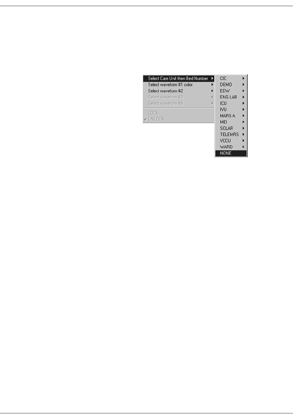
Clearing a Patient Window
To clear discharged patient information from the window and bring up
the Admit button, use the right-click menu.
1. Use the RIGHT mouse button to click anywhere inside a discharged
bed window. The right-click menu appears.
2. Slide the mouse over the Select Care Unit, then Bed Number text,
without pressing either mouse button. The text highlights, and a list
of units on the network pops up.
3. Without pressing either mouse button, slide the mouse pointer to
None at the bottom of the list. Click the left mouse button on None.
4. The popup list closes, and the patient window will now be empty,
except for an Admit button.
NOTE
On a locked bed, None is not an option. When beds are locked, you
must discharge from the single patient viewer.
387A
Revision D ApexPro Telemetry System 7-11
2001989-134
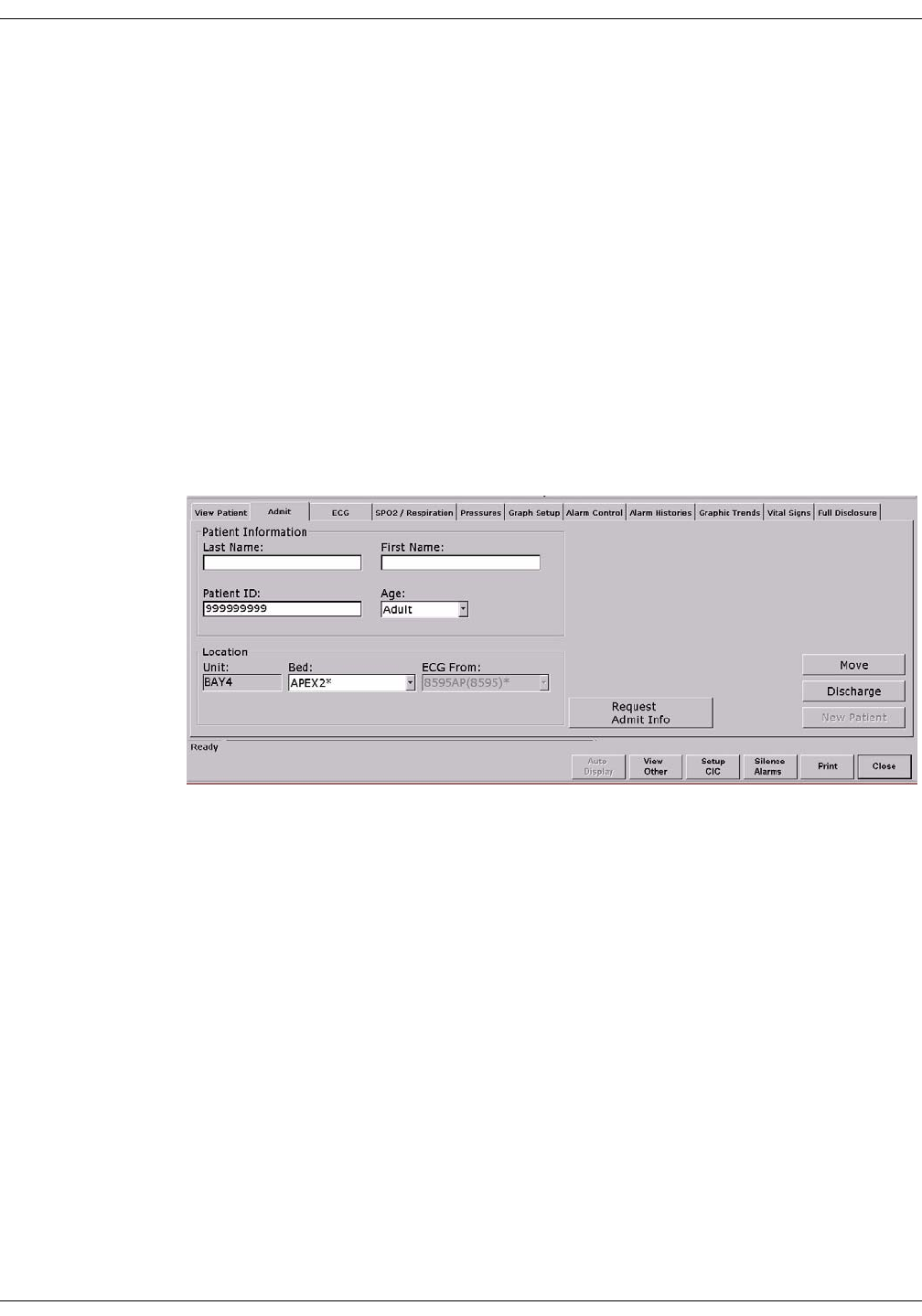
Admit/View a Patient: Move Telemetry Patients
Move Telemetry Patients
This option allows you to move a telemetry patient to a new bed within
the same care unit or to move Combo patients in and out of combo mode.
The Move feature is located on the Admit tab sheet on the CIC Pro.
To move a patient within the same care unit, follow this procedure:
1. At the CIC Pro, select the bed window of the patient you wish to
move.
2. Click on the Admit tab to bring the tab sheet to the front.
3. Select a new bed from the Location Bed: list.
4. The Save button changes to Move, click Move to move the patient to
the bed you selected from the bed list.
5. Select Yes when the Patient Move dialog is displayed.
Admit Patient Tab Sheet
A patient can not be moved to an unlocked bed if no bed slot is available.
A dialog window appears indicating that the change is disallowed
because the patient would be unmonitored.
Moving Locked/Unlocked Beds
The following guide lines apply when moving locked and unlocked beds.
A patient can be moved from an unlocked bed to another available
unlocked bed.
A patient can be moved from a locked bed to another available locked
bed.
A patient can be moved from an unlocked bed to an available locked
bed.
126A
7-12 ApexPro Telemetry System Revision D
2001989-134
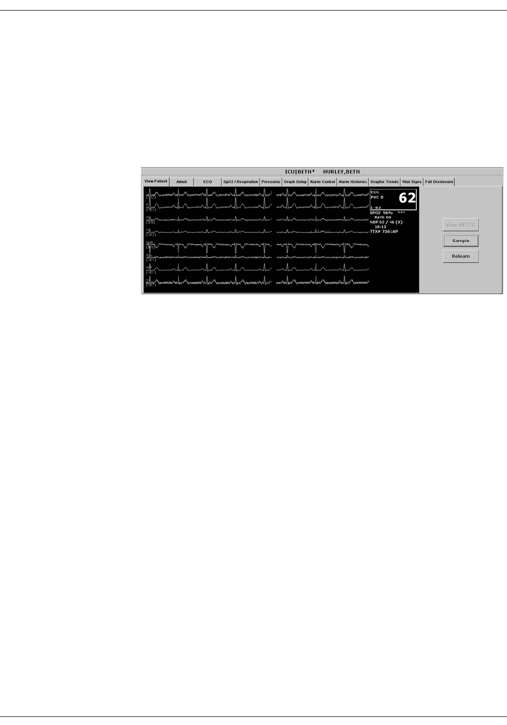
Admit/View a Patient: Viewing a Patient
Viewing a Patient
When you wish to see detailed information about a patient’s status, you
can use the View Patient tab in the single patient viewer.
1. Click in the bed window of the patient you wish to view. The display
rearranges to accommodate the single patient viewer at the bottom.
2. Click on the View Patient tab to bring it to the front.
The View Patient tab sheet shows all the information that normally
appears in patient’s bed window in the multiple patient viewer, and also
displays up to eight leads of ECG waveforms.
There are two buttons in the View Patient tab sheet that can be used for
telemetry patients. Their functions are described below.
NOTE
The third button, View All ECG, is dimmed when viewing telemetry
patients because all the ECG waveforms available for telemetry
patients are normally displayed.
Sample
Clicking on the Sample button records a sample of the patient’s real-time
ECG data. This sample is then stored in alarm histories, and can be
viewed in the Alarm Histories tab sheet under the title of Sample. For
more information about viewing alarm histories, refer to Chapter 10,
Patient Data, in this manual.
348D

Revision D ApexPro Telemetry System 7-13
2001989-134
Admit/View a Patient: Viewing a Patient
Relearn
Clicking on the Relearn button initiates a relearn of the patient’s ECG
rhythm. The relearn takes only a few seconds. The patient’s heart rate
reading will appear as Xs momentarily, and then be replaced by
numerics once the relearn is complete.
Use the relearn function whenever there has been a significant change in
the patient’s normal rhythm.
7-14 ApexPro Telemetry System Revision D
2001989-134
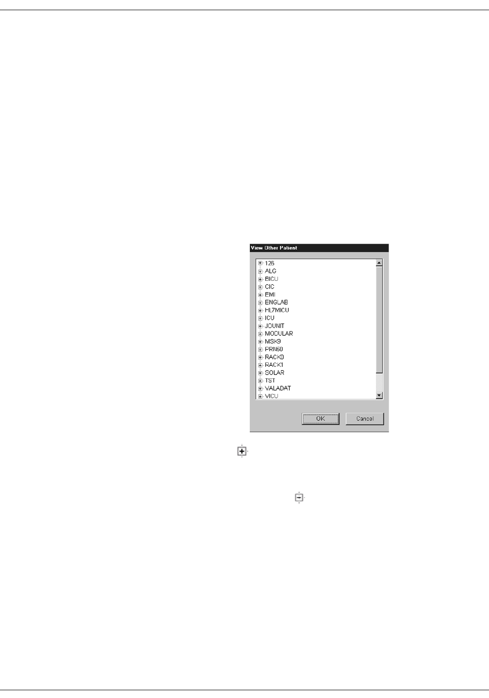
Admit/View a Patient: Viewing Another Patient
Viewing Another Patient
NOTE
When viewing a patient from another unit, you cannot make any
changes to the patient’s information or settings.
Viewing in the Single Patient Viewer
To display the single patient viewer of a patient on the network who is
not currently displayed on your CIC Pro, follow the steps below.
1. Click on the View Other button in the Main Menu at the bottom of
the CIC Pro display.
2. The View Other Patient window appears. This window displays all
the units currently available on your network.
3. Click on the next to the unit from which you wish to view a bed. A
list of beds admitted to that unit appears below the unit name.
NOTE
If a unit name has a next to it but no bed list below it, there
are no beds admitted into that unit.
4. Click on the bed name you wish to view. The name is highlighted.
5. Click on the OK button. The single patient viewer opens at the
bottom of the display, showing the viewed patient’s data.
339B
Revision D ApexPro Telemetry System 7-15
2001989-134
Admit/View a Patient: Viewing Another Patient
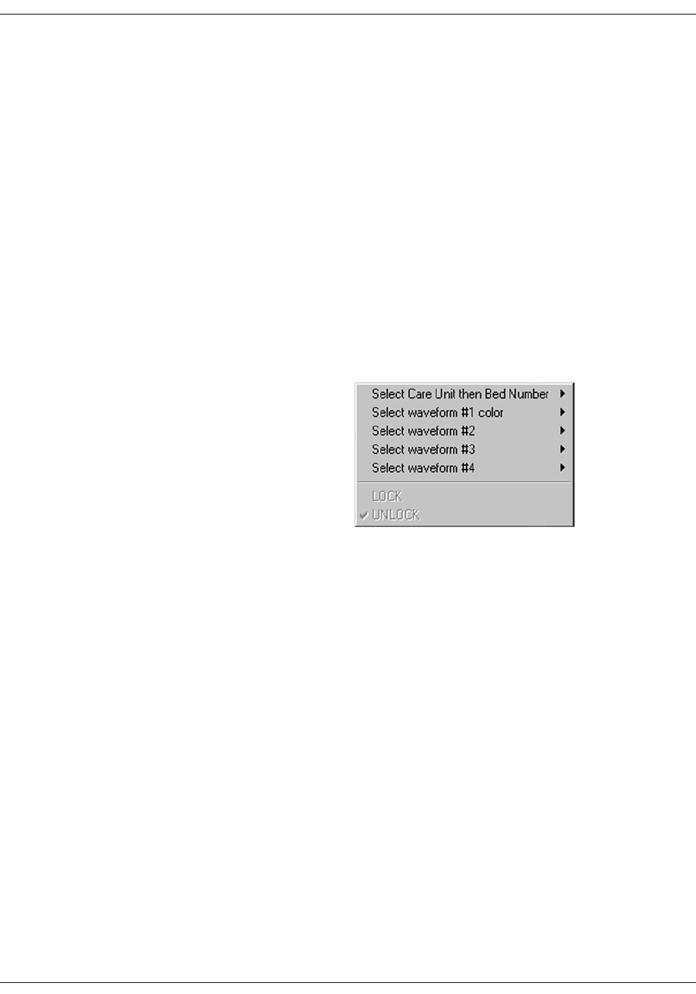
Viewing in the Multiple Patient Viewer
When in the multiple patient viewer, you can replace the data in any
unlocked bed window with the data from another patient on the network
who is not currently displayed on your CIC Pro.
NOTE
The data for the patient who was originally displayed in the bed
window you select will not be visible on your CIC Pro once you use
that patient’s bed window to view another patient.
To view another patient in the multiple patient viewer, follow the steps
below.
1. Use the right mouse button to click anywhere inside a bed window.
The right-click menu appears.
NOTE
You must use the right mouse button to access the right-click
menu.
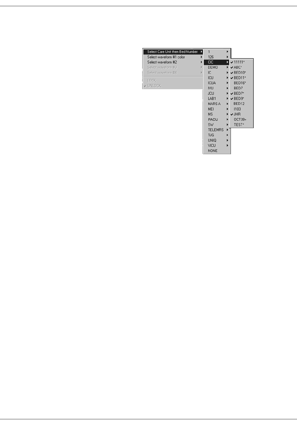
2. Slide the mouse over the Select Care Unit then Bed Number text,
without pressing either mouse button. The text highlights, and a list
of units on the network pops up.
349A
7-16 ApexPro Telemetry System Revision D
2001989-134
Admit/View a Patient: Viewing Another Patient
3. Without pressing either mouse button, slide the mouse pointer to the
unit name you wish to select a bed from. The unit name highlights,
and a list of beds on that unit pops up.
4. Without pressing either mouse button, slide the mouse pointer to the
bed you wish to view. The bed name becomes highlighted.
NOTE
A check mark next to a bed name means that the bed is already
being viewed at this CIC Pro.
5. Once you have chosen the bed you wish to view, and its bed name is
highlighted on this list, use the LEFT mouse button to click on the
bed name.
6. The popup lists close, and the viewed patient’s data appears in the
bed window.
For more detailed patient information, use the left mouse button to
click in the bed window. The single patient viewer will open at the
bottom of the display, allowing you to view all the patient’s data.
338A

Revision D ApexPro Telemetry System 7-17
2001989-134
Admit/View a Patient: Viewing Patients Through Alarm Condition Indicators
Viewing Patients Through Alarm Condition Indicators
You can open the single patient viewer for any patient in your care unit
who is experiencing an alarm condition.
When a patient experiences an alarm condition, a red button appears at
the bottom of the CIC Pro display. The button contains the unit name
and bed number, as well as the cause of alarm.
NOTE
Up to four of these red buttons display at one time, so only the four
highest-level alarms are indicated in this way.
To access the single patient viewer for the alarming patient, simply click
on the red button at the bottom of the display. The display rearranges to
accommodate the single patient viewer at the bottom of the display, and
all the patient’s information will be available to you.

7-18 ApexPro Telemetry System Revision D
2001989-134
Admit/View a Patient: Viewing Patients Through Alarm Condition Indicators

Revision D ApexPro Telemetry System 8-1
2001989-134
8Alarm Control

8-2 ApexPro Telemetry System Revision D
2001989-134
For your notes
Revision D ApexPro Telemetry System 8-3
2001989-134
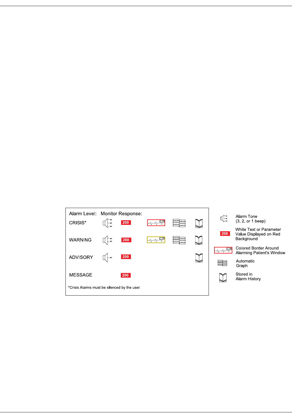
Alarm Control: Alarm Structure
Alarm Structure
The alarm structure of the CIC Pro is divided into two classifications:
Patient status alarms
System status alarms
Within each classification there are levels that correlate to the severity of
the condition that is causing the alarm. The levels and how the CIC Pro
responds to each are described below.
Patient Status Alarms
Patient status alarms are triggered by a patient condition that exceeds
parameter limits, or by an arrhythmia condition. Patient status alarms
provide the highest priority information.
The levels within the patient status alarm category and how the CIC Pro
responds to each are shown in the following chart. The chart begins with
the most critical type of alarm (Crisis) and ends with the least critical
type of alarm (Message).
NOTE
Only arrhythmia alarm conditions are stored in alarm histories.
Patient Status Alarms Chart
365A
8-4 ApexPro Telemetry System Revision D
2001989-134
Alarm Control: Alarm Structure
Colored Window Borders
Crisis and Warning alarms are indicated with a large border around the
individual patient’s bed window in the multiple patient viewer. This
border flashes on and off several times when the alarm occurs before
staying on. The color of the border indicates the severity of the alarm —
red for a Crisis alarm and yellow for a Warning alarm. When the alarm
is silenced, the colored border reverts to the black background.
NOTE
Only Crisis and Warning alarms activate the colored border.
Patients selected for single patient view have a white border in the
multiple patient viewer.
Automatic Alarm Graphs
A graph prints automatically when a patient experiences a Crisis or
Warning alarm. Arrhythmia alarm graphs run until the end of the alarm
event. The printer prints the 10 seconds of data that occurred
immediately before the event, and prints for the duration of the event.
The printer stops printing when the patient returns to a normal rhythm.
If a printer is not available at the time of the alarm event, a 20-second
graph is saved. This saved graph will print when a printer becomes
available.
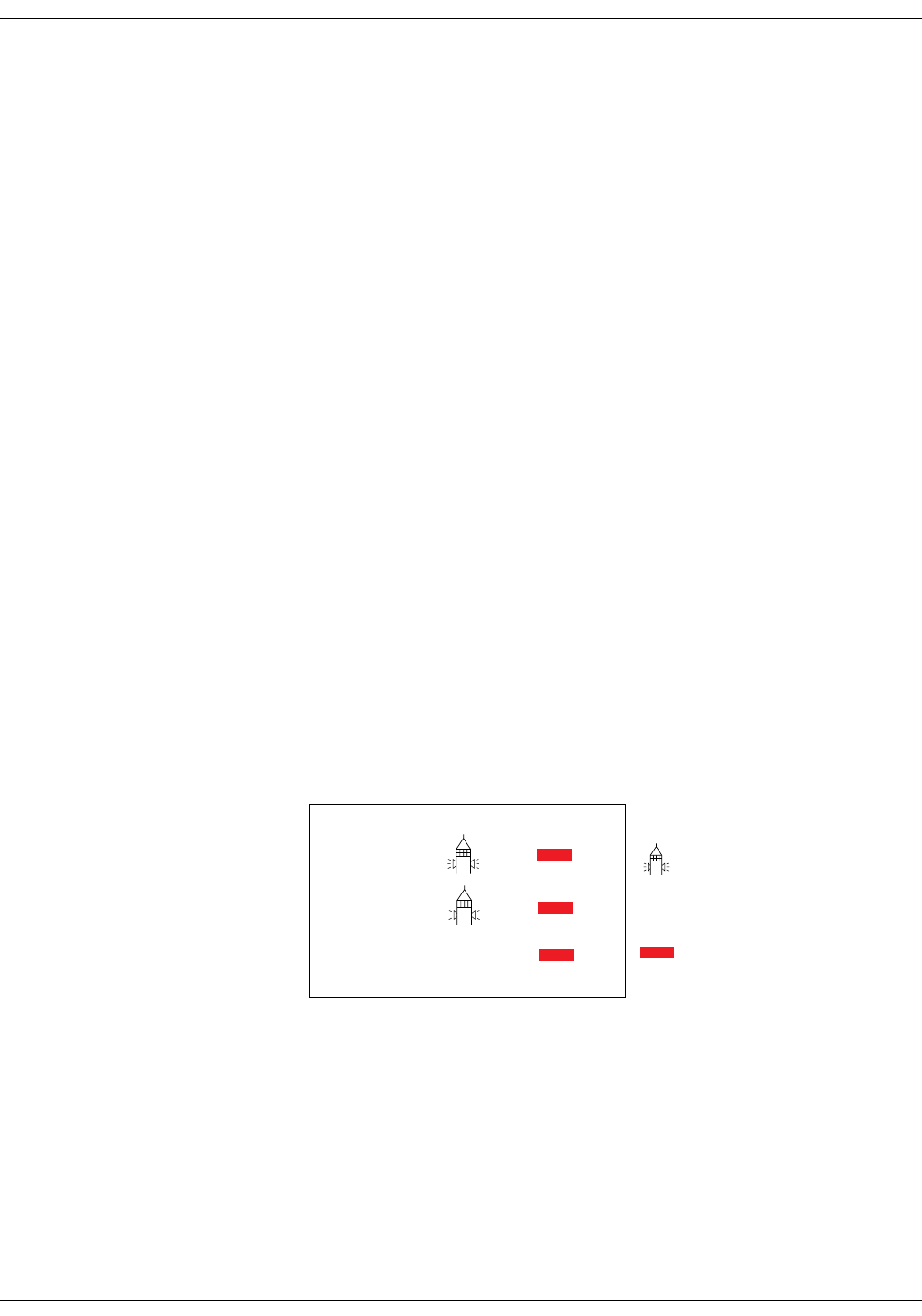
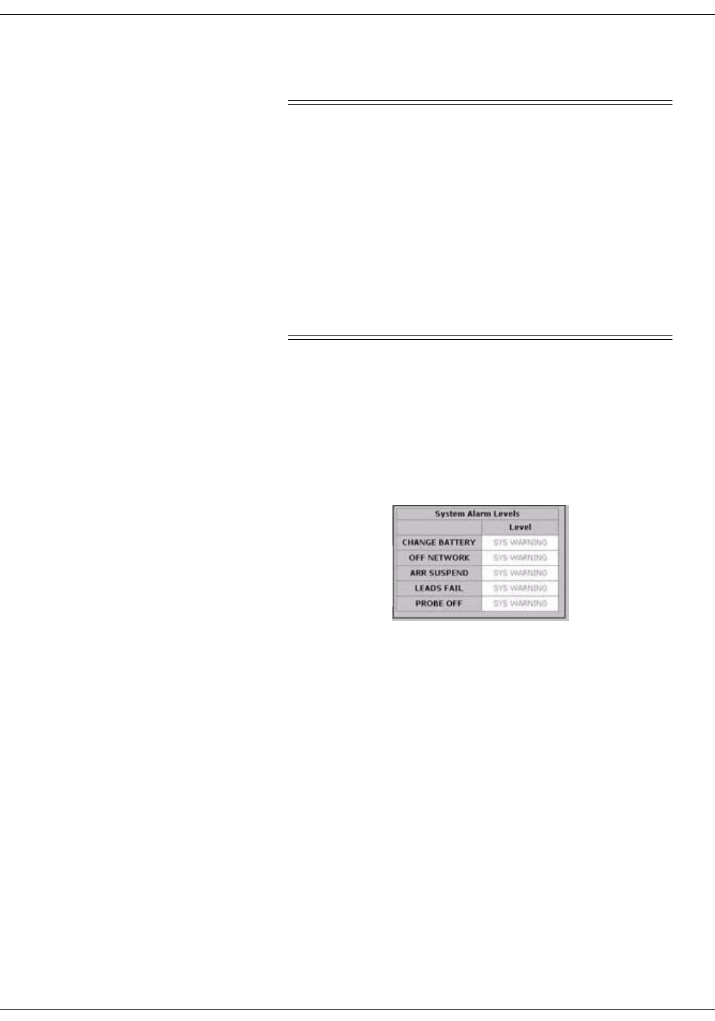
System Status Alarms
System status alarms are triggered by mechanical or electrical problems
and are of lesser priority than patient status alarms. The levels within
the system status alarm category and how the CIC Pro responds to each
are shown in the following chart.
System Status Alarms Chart
System status alarms cannot, in most cases, be moved from one level to
another. However, the CIC Pro allows you to set default alarm levels for
the following system alarms: CHANGE BATTERY, OFF NETWORK,
ARR SUSPEND, LEADS FAIL, PROBE OFF.
The System Alarm Levels are configurable in Telemetry Alarm Control
Defaults.
TEXT
TEXT
TEXT
TEXT
366B
Fog-horn Tone
Warning sounds continuously
Advisory sounds only once
White Text Displayed on Red
Background
Alarm Level: Monitor Response:
WARNING
ADVISORY
MESSAGE
Revision D ApexPro Telemetry System 8-5
2001989-134
Alarm Control: Alarm Control Tab
Alarm Control Tab
Parameter and arrhythmia alarm levels are, from most critical to least
critical, Crisis, Warning, Advisory, and Message.
Each alarm level elicits a specific response from the CIC Pro. The four
alarm levels are configurable. This means that an alarm can be moved
from one category to another if the default is not satisfactory to your
situation. This is done in the Alarm Control tab sheet for the patient
whose alarm settings you wish to adjust.
NOTE
ASYSTOLE and VFIB/VTAC alarms cannot be moved from the
Crisis level.
Accessing the Alarm Control Tab
1. Use the mouse to click in the window of the telemetry patient whose
alarm settings you wish to view or change.
2. The CIC Pro display rearranges as the single patient viewer opens at
the bottom of the display. Click on the patient’s Alarm Control tab to
bring the tab sheet to the front.
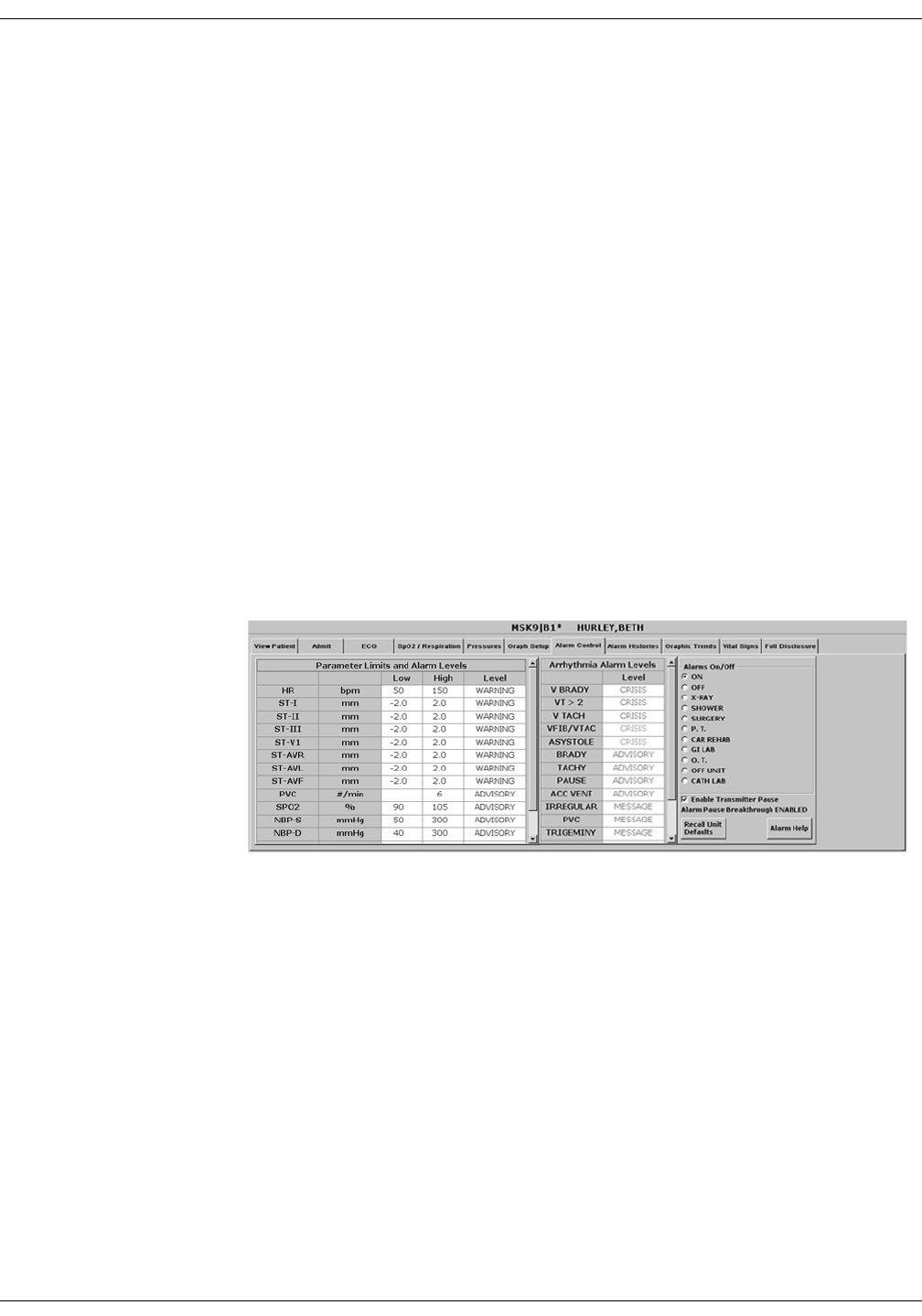
The telemetry patient Alarm Control tab sheet is divided into three
sections: Parameter Limits and Alarm Levels, Arrhythmia Alarm Levels,
and Alarms On/Off. The options on this tab sheet are detailed on the
following pages.
421C
8-6 ApexPro Telemetry System Revision D
2001989-134
Alarm Control: Alarm Control Tab
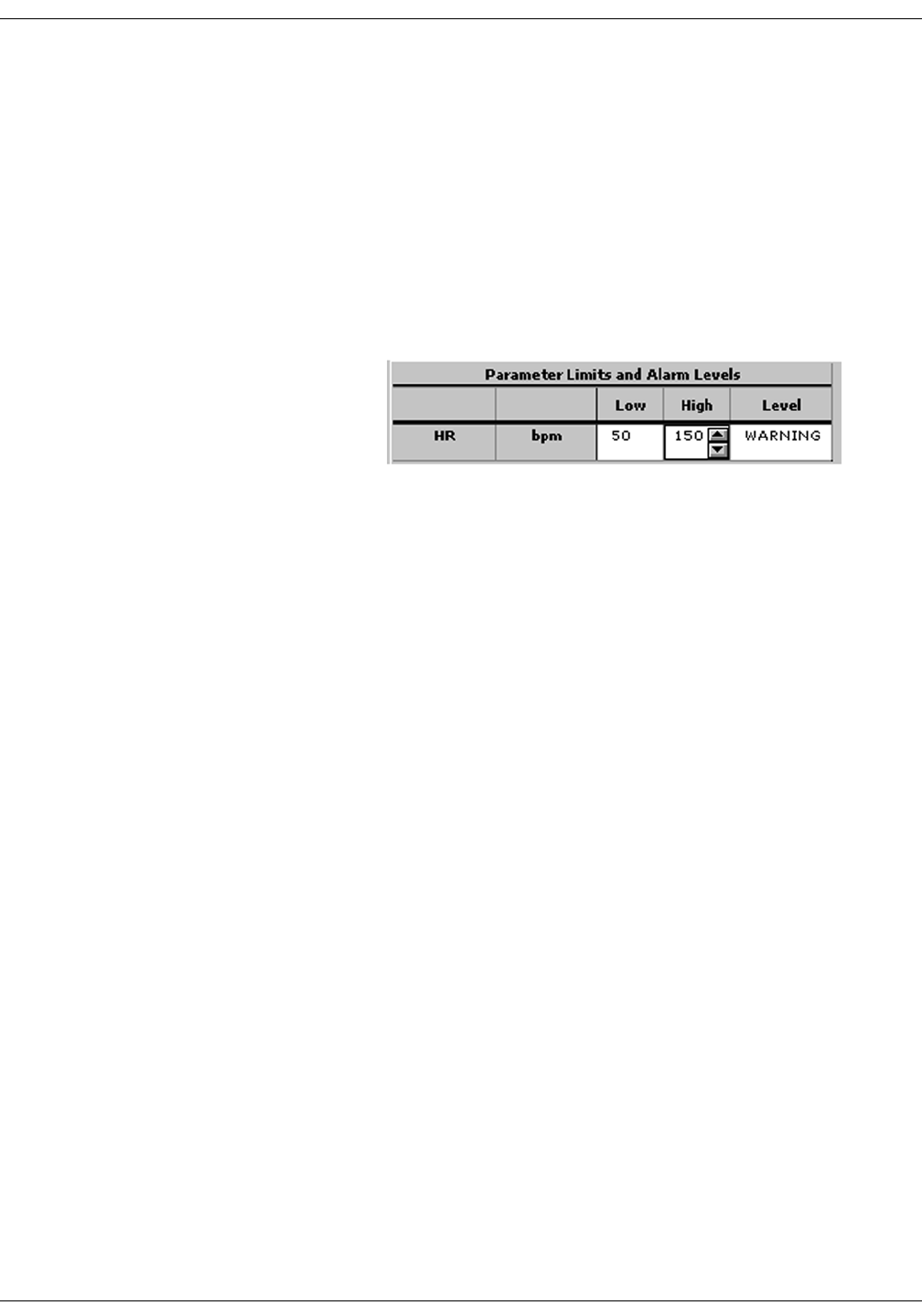
Parameter Limits
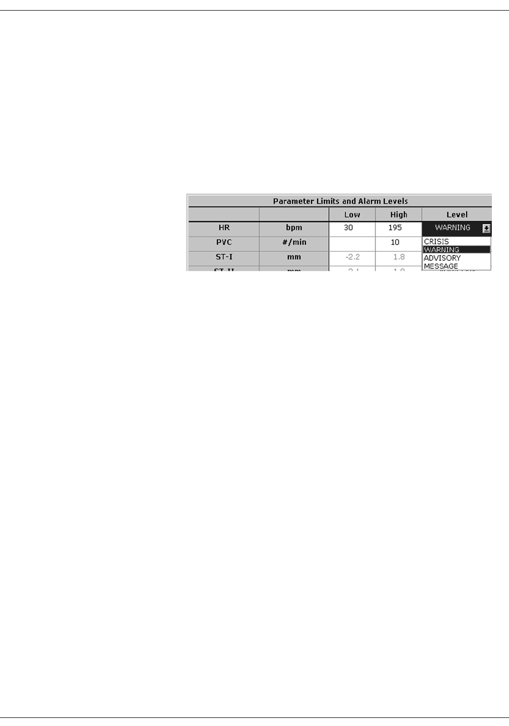
1. To change the individual patient’s settings for Parameter Limits and
Alarm Levels, click in the Low or High field for the parameter you
wish to change.
NOTE
The alarm limits for some parameters cannot be changed. To
indicate that they cannot be changed, the text in the Low and
High fields for these parameters always appears dimmed.
Once you click in the field, it is framed by a rectangle, and up and
down arrow buttons appear in the field.
NOTE
Alarms generated by parameter
limit violations are not stored in
Alarm Histories.
2. To increase or decrease the limit by 5, click on the up or down arrow
button.
To increase or decrease the limit in increments other than 5, use the
keyboard to enter a new limit value.
3. If you are finished making changes in the Alarm Control tab sheet,
click on the Close button in the bottom right corner of the display to
close the single patient viewer.
329A

Revision D ApexPro Telemetry System 8-7
2001989-134
Alarm Control: Alarm Control Tab
Parameter Alarm Levels
1. Click in the Level field for the parameter whose alarm level is to be
changed. A down arrow button appears in the field.
2. Click on the down arrow button. A popup list of alarm level selections
appears.
NOTE
Alarms are always sorted from top
to bottom in highest to lowest
priority. When you change a level,
the list is re-sorted to reflect the
change in alarm priority.
3. Click on the desired alarm level to select it.
4. If you are finished making changes in the Alarm Control tab sheet,
click on the Close button in the bottom right corner of the display to
close the single patient viewer.
331A
8-8 ApexPro Telemetry System Revision D
2001989-134
Alarm Control: Alarm Control Tab
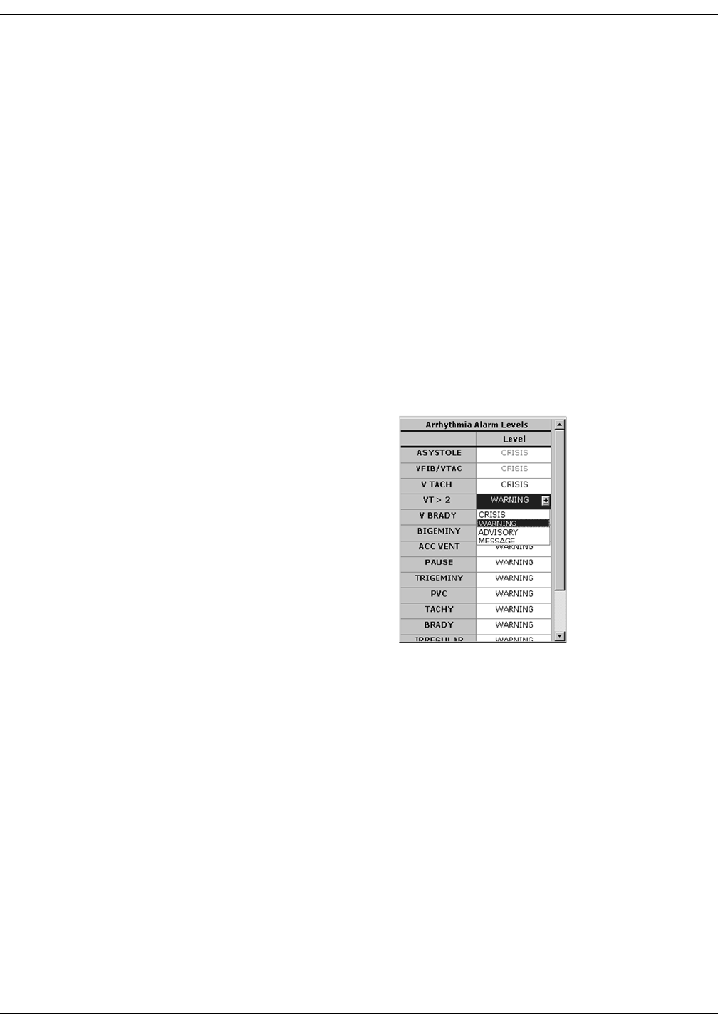
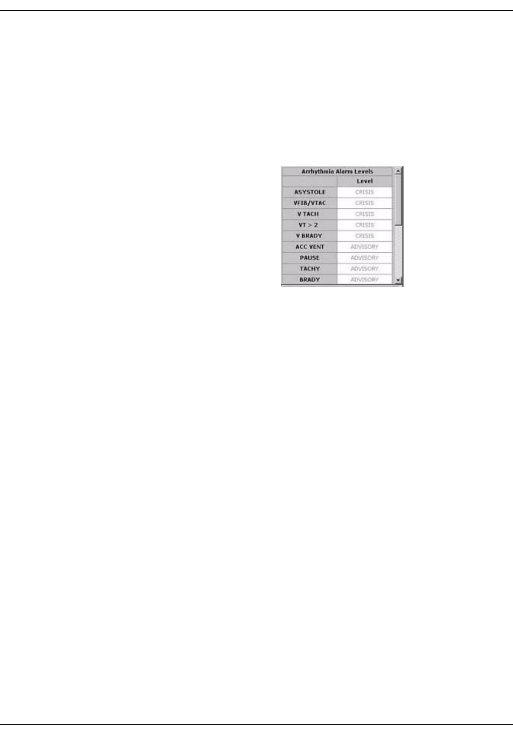
Arrhythmia Alarm Levels
1. To change the Arrhythmia Alarm Levels, click in the Level field of the
arrhythmia alarm you wish to change. A down arrow button appears
in the field.
NOTE
The Arrhythmia Alarm Levels for ASYSTOLE and VFIB/VTAC
cannot be changed. Therefore, the text in the Level field for these
alarms always appears dimmed.
NOTE
You may need to use the scroll bar on the right side of the
Arrhythmia Alarm Levels section in order to view the
arrhythmia alarm that you wish to modify.
NOTE
Alarm levels are usually shown in black type. An alarm level
shown in blue indicates that it is NOT the default level.
2. Click on the down arrow button. A popup list of alarm level selections
appears.
3. Click on your choice to select it.
4. If you are finished making changes in the Alarm Control tab sheet,
click on the Close button in the bottom right corner of the display to
close the single patient viewer.
325B
Revision D ApexPro Telemetry System 8-9
2001989-134
Alarm Control: Alarm Control Tab
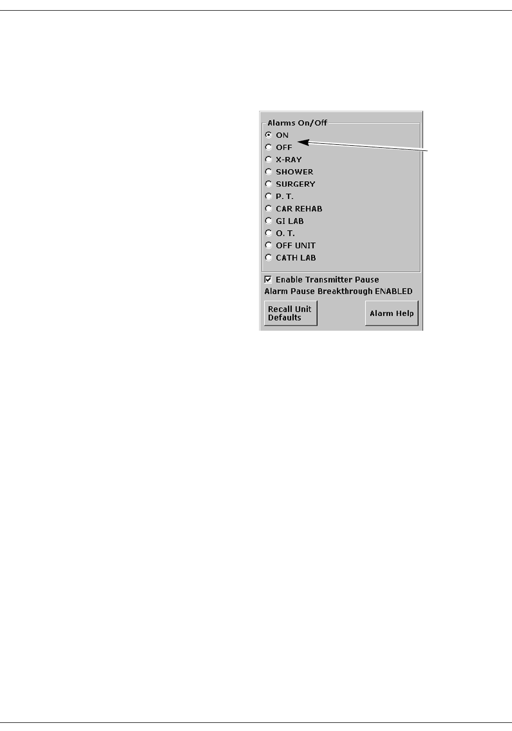
Alarms On/Off
To turn a telemetry patient’s alarms on or off, click on the appropriate
radio button or on the text itself in the Alarms On/Off section of the
Alarm Control tab.
Selecting Off turns all alarms off until you turn them back on by
selecting On.
NOTE
Refer to the Alarm Pause Breakthrough section in this chapter for
important information about turning alarms off.
ON and OFF
buttons
334B

8-10 ApexPro Telemetry System Revision D
2001989-134
Alarm Control: Alarm Control Tab
Alarm Off Reason
Selecting from a list of reasons, you can define why alarms have been
turned off. This text is displayed in addition to the ALARMS OFF
message in the patient’s window at the CIC Pro.
The following are the options for alarms off reasons.
Selecting OFF turns all alarms off until you turn them back on.
Selecting any reason establishes an alarm pause state for 5 minutes
in the presence of a valid waveform. After 5 minutes, alarms will
reactivate if the patient is within range of the antenna system for 15
seconds or longer. If the patient remains out of antenna range, the
alarm pause state will continue until the patient re-enters antenna
range for 15 seconds or longer.
NOTE
The patient must be in antenna range for the alarm pause state
to cease.
WARNING
Alarms do not sound, alarm histories are not stored, and
alarm graphs do not print during an alarms off with
reason condition.
Alarms Off Reason Text Displayed At CIC Pro Text Printed On Graph
On (no text) (no text)
Off ALARMS OFF OFF
X-ray XRAY X-RAY
Shower SHOWER SHOWER
Surgery SURGERY SURGERY
Physical therapy P.T. PHYSICAL THERAPY
Cardiac rehab CAR REHAB CARDIAC REHAB
GI Lab GI LAB GI LAB
Occupational therapy O.T. OCCUPATIONAL THERAPY
Off unit OFF UNIT OFF UNT
Cath Lab CATH LAB CARDIAC CATH LAB

Revision D ApexPro Telemetry System 8-11
2001989-134
Alarm Control: Alarm Control Tab
The alarms off reason appears in the event trend for graphic trends.
If the patient is in LEADS FAIL or NO TELEM and an alarms off
reason is selected, the reason is displayed in the waveform window.
NOTE
After the patient has returned to antenna range and/or alarms have
been turned back on, verify that the patient’s waveforms are
displayed at the CIC Pro or bedside monitor.
NOTE
Refer to the Alarm Pause Breakthrough section in this chapter for
important alarm pause information.
Enable Transmitter Pause
The Enable Transmitter Pause check box, when checked, allows alarms
to be paused by pressing both ApexPro transmitter buttons
simultaneously.
To enable the transmitter pause option for a telemetry patient admitted
to the CIC Pro, click in the Enable Transmitter Pause check box. A check
mark appears in the check box.
To disable the transmitter pause option, click in the Enable Transmitter
Pause checkbox. The check mark is removed from the check box and the
option is disabled.
NOTE
If Off is selected for the Transmitter Alarm Pause option in the
Telemetry Unit Defaults tab sheet, no check box appears on the tab.
To make the Enable Transmitter Pause option active (check box
available), either Enabled or Disabled must be selected for the
Transmitter Alarm Pause option in the Telemetry Unit Defaults tab
sheet. Refer to Chapter 6, Telemetry Setup, for information about
setting the Transmitter Alarm Pause option.
Alarm Pause Breakthrough Enabled/Disabled
Refer to the Alarm Pause Breakthrough section in this chapter for
information about this alarm pause breakthrough status message.
8-12 ApexPro Telemetry System Revision D
2001989-134
Alarm Control: Alarm Control Tab
Recalling Unit Defaults
To recall the preset telemetry patient unit defaults for all options in the
Alarm Control tab, simply click on the Recall Unit Defaults button on the
bottom right side of the Alarm Control tab sheet. All data on the tab
sheet will clear, and after a moment the preset unit defaults will appear.
In addition, clicking on the Recall Unit Defaults button also restores the
default graph locations and settings on the patient’s ECG tab sheet.
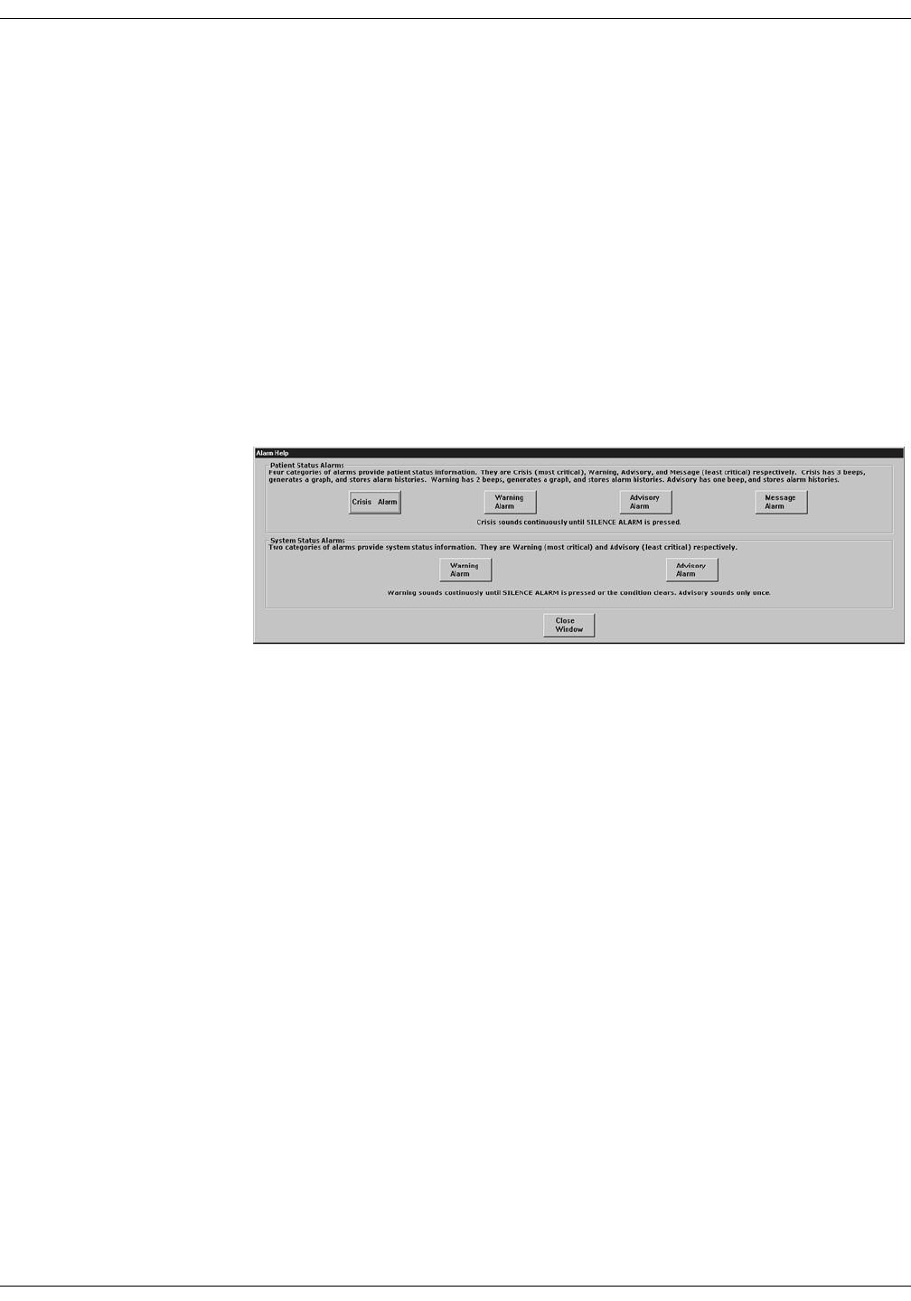
Alarm Help
For additional information about alarms, click on the Alarm Help button
at the bottom right side of the Alarm Control tab sheet. An Alarm Help
window appears.
You can click on the buttons in this window to hear how each type of
alarm sounds. When you are finished browsing the window, click on the
Close Window button to close the window and return to the single patient
viewer.
323A
Revision D ApexPro Telemetry System 8-13
2001989-134
Alarm Control: Alarm Control Tab
Printing Alarm Settings
A telemetry patient’s Alarm Control tab sheet can be printed, showing all
current alarm settings and limits. Click on the Print button in the main
menu to start a printout of the Alarm Control tab sheet.
The Alarm Control tab sheet prints at the Print Window location. For
more information about setting the Print Window location, refer to
Chapter 9, Printing, in this manual.
NOTE
The Alarm Control tab sheet must be the front tab of the single
patient viewer in order to print it. Click on the Alarm Control tab to
bring it to the front if necessary.
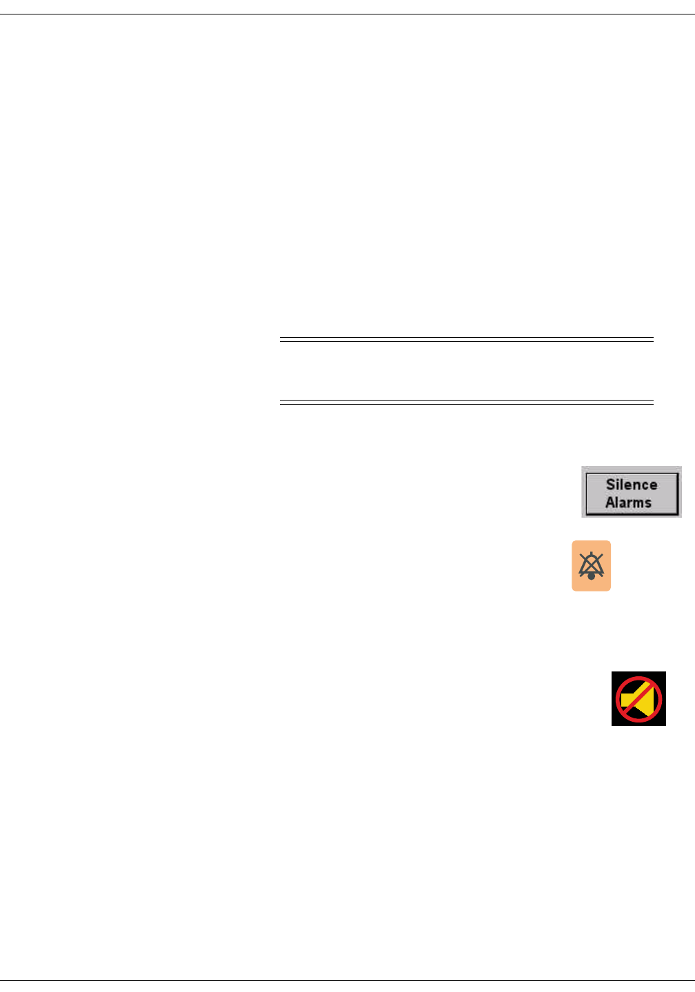
Silencing Alarms
WARNING
Do NOT continuously press the silence key. You may
inadvertently silence new patient alarms.
You can silence the audible alarm tones in one of two ways:
Use the mouse and click on the Silence Alarms
button located on the display monitor’s screen.
Press the Silence Alarms key located on the
keyboard.
Alarm Silence Icon
When an alarm is silenced, a visual indication (Alarm
Icon) of the silenced alarm is displayed at the CIC Pro.
The alarm silence icon is displayed in the ECG
parameter window next to the ECG heart rate. The
alarm silence icon remains on the display for one
minute unless a new alarm occurs.
NOTE
If you are monitoring telemetry patients, new alarms of equal or
greater priority level break the alarm silence condition.
427A
426A
Alarm Silence
Icon

8-14 ApexPro Telemetry System Revision D
2001989-134
Alarm Control: Alarm Pause Breakthrough
Alarm Pause Breakthrough
The alarm pause breakthrough feature allows any crisis level alarm to
“break through” (interrupt) an alarm pause and sound at the CIC Pro.
In other words, when this feature is turned on in the Telemetry Unit
Defaults tab sheet, Crisis level alarms will sound at the CIC Pro, even if
an alarm pause is in effect.
NOTE
The Alarm Pause Breakthrough feature defaults to Always On. It
must be set to Always Off in the Telemetry Unit Defaults tab sheet
BEFORE admitting a telemetry patient if you do not wish to have
Crisis level alarms break through alarm pauses.
This feature cannot be set on an individual patient basis. It is either
on or off for all telemetry patients admitted to the CIC Pro. A status
message on each patient’s Alarm Control tab sheet indicates whether
it is enabled (on) or disabled (off).
The chart below illustrates the function of the alarm pause breakthrough
feature during the various alarm states.
After a Crisis level alarm has broken through an alarm pause, the
telemetry system does NOT return to an alarm pause state. All alarms at
any alarm level will sound at the CIC Pro.
Alarm State Alarm Pause Breakthrough Function
Alarms on No alarm pause breakthrough; all alarms are on.
Alarms off No alarm pause breakthrough; all alarms are off.
Alarm off reason (X-ray,
shower, etc.)
Alarms are paused; Crisis level alarms will break through
the alarm off reason if the patient is in antenna range.
Alarms paused from the
ApexPro transmitter
Alarms are paused; Crisis level alarms will break through
the alarm pause.

Revision D ApexPro Telemetry System 8-15
2001989-134
Alarm Control: Alarm Pause Breakthrough
If you wish to continue pausing alarms after an alarm pause
breakthrough occurs, you must re-initiate the alarm pause:
1. To re-initiate an alarms off with reason condition, select the alarms
off reason in the telemetry patient’s Alarm Control tab sheet.
2. To re-initiate an alarm pause from the ApexPro transmitter, press
both transmitter buttons simultaneously twice.
NOTE
The transmitter buttons must be pressed once to “end” the alarm
pause at the transmitter, then a second time to start a new alarm
pause at the transmitter (see below).
The Pause Alarm LED on the ApexPro transmitter continues to flash
after an alarm pause breakthrough occurs. This is because there is no
communication from the CIC Pro back to the ApexPro transmitter to
indicate that the alarm pause has ended. After an alarm pause
breakthrough occurs, you can turn off the flashing Pause Alarm LED by
pressing both transmitter buttons simultaneously.
8-16 ApexPro Telemetry System Revision D
2001989-134
Alarm Control: Unit Default Settings for Alarms
Unit Default Settings for Alarms
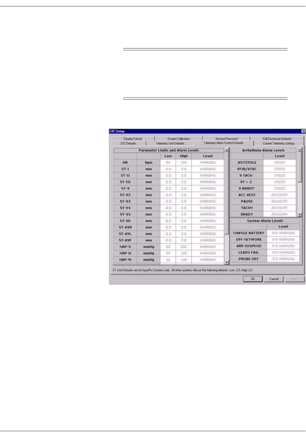
Telemetry Alarm Control Defaults
You can set Telemetry Unit Defaults for parameter limits and alarm
levels, as well as for arrhythmia alarm levels. These defaults are in effect
for all telemetry patients admitted to your unit, unless they are modified
in an individual patient’s Alarm Control tab sheet (for more information,
see the Alarm Control Tab section in this chapter).
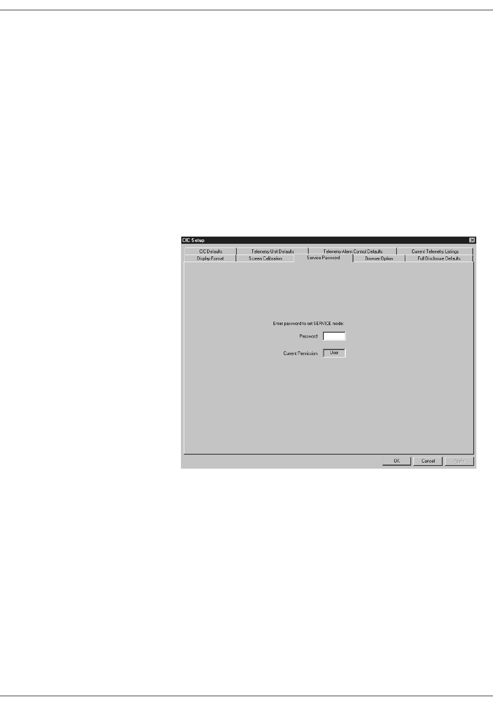
To set telemetry alarm control defaults, follow the steps below:
1. Click on the Setup CIC button at the bottom of the CIC Pro display. A
set of tabs appears.
2. Click on the Service Password tab to bring it to the front.
318B
Revision D ApexPro Telemetry System 8-17
2001989-134
Alarm Control: Unit Default Settings for Alarms
3. Use the keyboard to enter the service password, then click the Apply
button. The Current Permission entry changes from User to Service.
CAUTION
The service mode is intended for use only by qualified
personnel with training and experience in its use. The
consequences of misuse include loss of patient data,
corruption of the CIC Pro operating system software, or
disruption of the entire Unity network.
4. Click on the Telemetry Alarm Control Defaults tab to bring it to the
front.
319D

8-18 ApexPro Telemetry System Revision D
2001989-134
Alarm Control: Unit Default Settings for Alarms
Parameter Limits
5. To change the unit defaults for Parameter Limits and Alarm Levels,
use the mouse to click in the Low or High field for the parameter you
wish to edit. The field is framed by a rectangle, and up and down
arrow buttons appear in the field.
6. To increase or decrease the limit by 5, click on the up or down arrow
button.
To increase or decrease the limit in increments other than 5, use the
keyboard to enter a new limit value.
7. Once you have set the desired limit, click on the Apply button for the
changes to take effect.
NOTE
If you make only one change, you do not need to click on the
Apply button. The change will take effect automatically, and the
Apply button will appear dimmed.
8. If you are finished making changes to the Telemetry Alarm Control
Defaults tab sheet, click the OK button.
329A
Revision D ApexPro Telemetry System 8-19
2001989-134
Alarm Control: Unit Default Settings for Alarms
Parameter Alarm Levels
To make a change in the telemetry unit default alarm level for a
parameter, first access the Telemetry Alarm Control Defaults tab as
described in the Telemetry Alarm Control Defaults section in this
chapter. Then follow the procedure below.
1. In Telemetry Alarm Control Defaults tab, use the mouse to click in
the Level field of the parameter for which the alarm level is to be
changed. A down arrow button appears in the field.
2. Click on the down arrow button. A popup list of alarm level selections
appears.
3. Click on the desired alarm level to select it.
4. Once you have set the desired level, click the Apply button for the
changes to take effect.
5. If you are finished making changes to the Telemetry Alarm Control
Defaults tab sheet, click the OK button.
331A
8-20 ApexPro Telemetry System Revision D
2001989-134
Alarm Control: Unit Default Settings for Alarms
Arrhythmia Alarm Levels
To make a change in the telemetry unit default alarm level for
arrhythmia alarms, first access the Telemetry Alarm Control Defaults
tab as described in the Telemetry Alarm Control Defaults section in this
chapter. Then follow the procedure below.
1. In the Telemetry Alarm Control Defaults tab, the arrhythmia alarm
levels for which unit defaults can be set appears on the right side of
the window:
2. Click in the Level field of the arrhythmia alarm you wish to modify. A
down arrow button appears in the field.
NOTE
The arrhythmia alarm levels for ASYSTOLE and VFIB/VTAC
cannot be changed. Therefore, the text in the Level field for these
alarms always appears dimmed.
3. Click on the down arrow button. A popup list of alarm level selections
appears.
4. Click on your choice to select it.
5. Once you have set the desired level, click the Apply button for the
changes to take effect.
If you are finished making changes to the Telemetry Alarm Control
Defaults tab sheet, click the OK button.
333C
Revision D ApexPro Telemetry System 8-21
2001989-134
Alarm Control: Unit Default Settings for Alarms
System Alarm Levels
WARNING
ADJUSTING SYSTEM ALARM LEVELS — The LEADS
FAIL alarm indicates that one or more electrodes are not
connected to the patient and, as a result, there is loss of
all waveforms and arrhythmia analysis. The ARR
SUSPEND alarm indicates that arrhythmia conditions
are not being detected and therefore alarms associated
with arrhythmias will not occur. The LEADS FAIL and
ARR SUSPEND alarms should be adjusted to a lower
priority level only by experienced qualified personnel and
with great caution. Adjusting these alarms to a lower
priority level may result in reduced awareness of
conditions that indicate the loss of patient monitoring.
To make a change in the telemetry unit default alarm level for system
alarms, first access the Telemetry Alarm Control Defaults tab as
described in the Telemetry Alarm Control Defaults section in this
chapter. Then follow the procedure below.
1. In the Telemetry Alarm Control Defaults tab, the system alarm levels
for which unit defaults can be set appears on the right side of the
window:
2. Click in the Level field of the system alarm you wish to modify. A
down arrow button appears in the field.
3. Click on the down arrow button. A popup list of alarm level selections
appears.
4. Click on your choice to select it.
5. Once you have set the desired level, click the Apply button for the
changes to take effect.
If you are finished making changes to the Telemetry Alarm Control
Defaults tab sheet, click the OK button.
430A

8-22 ApexPro Telemetry System Revision D
2001989-134
Alarm Control: Unit Default Settings for Alarms
For your notes

Revision D ApexPro Telemetry System 9-1
2001989-134
9Printing

9-2 ApexPro Telemetry System Revision D
2001989-134
For your notes

Revision D ApexPro Telemetry System 9-3
2001989-134
Printing: Initiating a Manual Graph
Initiating a Manual Graph
If you click on a patient’s ECG parameter window, a continuous graph is
initiated for the patient. Clicking on the ECG parameter window again
will stop the graph.
The PRN 50 digital writer and the Direct Digital Writers (DDW) print
patient data (generally referred to as a graph or graph strip). Data can
also be printed on a laser printer.
The waveforms graphed and graph speed are controlled in the individual
patient’s Graph Setup tab sheet. Unit defaults for telemetry patients can
be set in the CIC Defaults tab sheet and the Telemetry Unit Defaults tab
sheet. Refer to Chapter 6, Telemetry Setup, for more information on
setting telemetry unit defaults.
Automatic Alarm Graphs
A graph prints automatically when a patient experiences a Crisis or
Warning alarm condition. Arrhythmia alarm graphs run until the end of
the alarm event. The printer prints up to 10 seconds of data that
occurred immediately before the event, and prints for the duration of the
event. The printer stops printing when the patient returns to a normal
rhythm.
If a printer is not available at the time of the alarm event, a 20-second
graph is saved. This saved graph will print when a printer becomes
available.
9-4 ApexPro Telemetry System Revision D
2001989-134
Printing: Initiating a Manual Graph
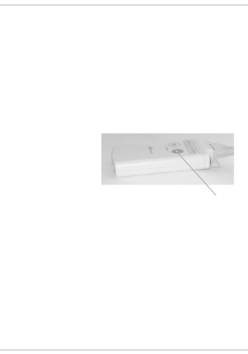
Transmitter Initiated Graphs (Manual Graphs)
When the Graph button on the ApexPro transmitter is pressed, a 20-
second graph strip is printed at a speed of 25 millimeters per second.
When an IMPACT.wf paging system (version II or later) is also available
in the same care unit, pressing the Graph button enables the View on
Demand feature (also called the Apex Graph Button Push feature). The
IMPACT.wf server generates a manually initiated sample page or
snapshot of the patient’s ECG waveform and any other enabled/
monitored non-arrhythmia parameters.
When you press the Graph button on the ApexPro transmitter, it
generates both an IMPACT.wf update page as well as a standard ECG
waveform graph at the CIC Pro. The IMPACT.wf page is labeled
“Sample” when this data is displayed on the IMPACT.wf receiver and
stored in history. Additionally, all pagers assigned to the patient receive
a page.
Graph button
309B

Revision D ApexPro Telemetry System 9-5
2001989-134
Printing: Initiating a Manual Graph
Graph Messages
One of the following messages is displayed on the CIC Pro screen during
graphing:
GRAPH ALARM—An alarm graph was initiated and is running.
GRAPH MANUAL—A manual graph was requested and is running.
GRAPH TTX—The Graph button on the transmitter was pressed and a
20-second graph strip is running.
PRINTING—A non-real time graph is currently being printed.
SAVING—An alarm or a manual graph has been requested but the
writer is in use; the writer door is open; or the writer is out of paper. The
graph is being saved until the writer is available. (The most recent 20-
second alarm or manual graph will be saved.)

9-6 ApexPro Telemetry System Revision D
2001989-134
Printing: Graph All Patients
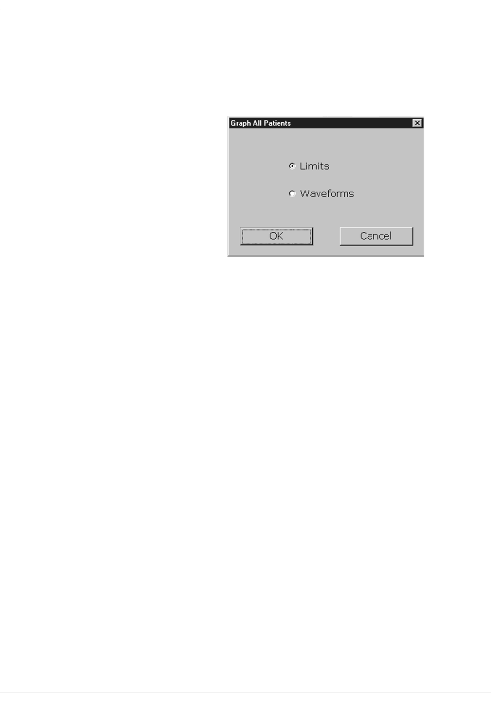
Graph All Patients
Clicking on the Print button at the bottom of the CIC Pro display sends a
Graph All Patients request to all beds displayed on the CIC Pro,
initiating a 10-second graph for each admitted telemetry patient. When
this option is selected for telemetry patients, graph requests always print
at a speed of 25 millimeters per second.
NOTE
This Graph All Patients function is only available when the single
patient viewer is closed. If a single patient viewer is open, selecting
Print from the main menu initiates a printout of whichever tab sheet
is in front.
The print process stops automatically. If the Graph Stop control key is
pressed on the external DDW, the current patient’s graph stops and the
writer begins to print a 10-second graph for the next patient.
If a patient’s data is currently printing or is being saved to print when a
Graph All Patients request is initiated, this patient’s data will not be
included in the Graph All Patients graph. This patient’s data will print
independently of the Graph All Patients graph.
Clicking on the ECG parameter window for a patient whose data is
saving will cancel the Graph All Patients request for that patient.
If, while a Graph All Patients request is in progress, an arrhythmia
alarm occurs for a patient, the alarm data will replace the data that was
saved for the Graph All Patients request. The alarm data will then
appear on the graph printout.
If, while a Graph All Patients request is running, a telemetry patient
initiates a graph from his or her telemetry transmitter, the saved data
for the Graph All Patients graph will be replaced by data from the
patient’s telemetry transmitter. The data from the telemetry transmitter
will then appear on the graph printout.
Revision D ApexPro Telemetry System 9-7
2001989-134
Printing: Graph All Patients
Initiating a Graph All Patients Request
To initiate a Graph All Patients request, follow these steps.
1. Click on the Print button at the bottom of the CIC Pro display. The
Graph All Patients window opens.
2. Click on Limits or Waveforms.
Selecting Limits graphs all patient limits.
Selecting Waveforms graphs all patient waveforms.
3. Click on the OK button to complete the Graph All Patients request.
378A

9-8 ApexPro Telemetry System Revision D
2001989-134
Printing: Graph Location Settings
Graph Location Settings
Graphs print at the graph locations specified in the patient’s Graph
Setup tab sheet. Upon admission of a patient, these locations are set
from the unit defaults, but they can be modified if desired.
Following are guidelines for Graph Location:
Manual graphs and print window requests print at the CIC Pro
where the graph was requested, provided that CIC Pro has the same
type of writer or printer as the graph location set for the patient for
that type of graph. If the CIC Pro where the graph was requested
does not have the same type of writer or printer, the graph prints to
the patient’s specified graph location.
If a telemetry patient is duplicated on another CIC Pro, alarm
graphs continue to print at the clinical information center where the
patient was first displayed (admitted).
If using the move feature, the patient’s graph settings are retained as
set on the original clinical information center.
If a patient displays on a clinical information center that is not
connected to a printer, the graph settings default to the graph
location designated in the unit defaults. See “Telemetry Unit
Defaults” on page 6-7.
If no graph location is defined for a telemetry patient at the time of
admission, the message “Saving” displays. Graphs are not sent to
printers outside the unit.
For more information on designating graph locations, refer to the Graph
Location Controls section in this chapter.

Revision D ApexPro Telemetry System 9-9
2001989-134
Printing: Stopping a Graph
Stopping a Graph
To stop a graph request that has been sent to an external writer, press
its Graph Stop control key. This stops any graph already in process. If
this key is pressed when no graph is in process, it advances the paper in
the writer.
A manual graph may also be stopped by clicking on the patient's ECG
parameter window. An Automatic Alarm Graph may be stopped by
clicking on the patient's ECG window twice, once to change the graph to
a manual graph, and then a second time to stop the graph.
NOTE
Because the CIC Pro can communicate with many laser printers, the
specific procedure for stopping a graph sent to a laser printer is not
documented in this manual. Refer to the laser printer manufacturer’s
instructions.

9-10 ApexPro Telemetry System Revision D
2001989-134
Printing: Graph Paper Out Indicator
Graph Paper Out Indicator
When there is no graph paper in the writer (or the door is open), the
message Graph Paper Out/Door Open is displayed at the top of the
screen.
When printing to a laser printer, a similar status message is displayed if
the printer is unable to print.
NOTE
Because the CIC Pro can communicate with many laser printers,
specific status messages are not documented in this manual.
Revision D ApexPro Telemetry System 9-11
2001989-134
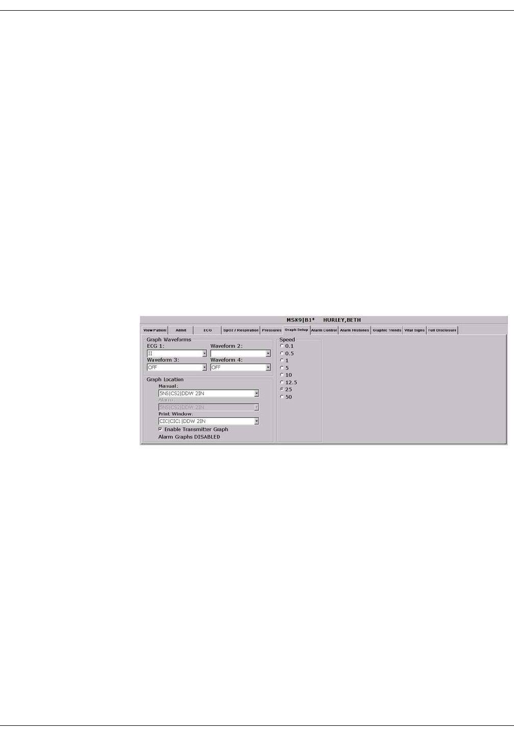
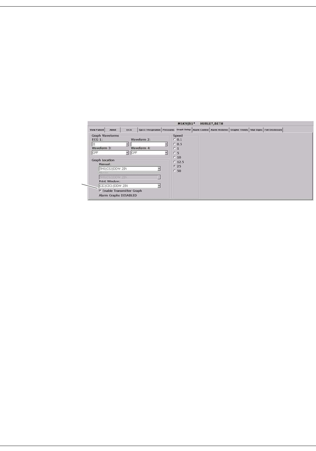
Printing: Graph Setup Tab Sheet
Graph Setup Tab Sheet
The Graph Setup tab sheet allows you to define the waveforms to be
graphed, change the graph location and speed, and turn the telemetry
transmitter graph on and off.
NOTE
Changes made in the Graph Setup tab sheet affect only the patient
currently being viewed.
To make changes to graph information for all telemetry patients in
the unit, you must use the CIC Setup and the Telemetry Unit
Defaults tab sheets (refer to Chapter 6, Telemetry Setup, in this
manual).
To view a patient’s Graph Setup tab sheet, follow these steps.
1. Click on the desired patient’s information in the multiple patient
viewer. The single patient viewer for that patient opens.
2. Click on the Graph Setup tab. The Graph Setup tab sheet moves to
the front.
357C

9-12 ApexPro Telemetry System Revision D
2001989-134
Printing: Graph Setup Tab Sheet
Graph Waveforms Controls
The Graph Waveforms controls allow you designate which waveforms
should print in which positions on a patient’s graph printout.
ECG 1 Control
1. Click in the ECG 1 field. A down arrow button is displayed next to
the waveform currently in the ECG 1 position.
2. Click on the down arrow to display a list of available ECG
waveforms.
3. Click on the desired ECG waveform. The ECG 1 menu closes, with
the selected ECG waveform name remaining visible.
NOTE
This action also changes displayed waveforms in the multiple patient
viewer.
Waveform 2, Waveform 3, and Waveform 4
1. Click in the field for the waveform you wish to designate. A down
arrow icon is displayed next to the waveform currently in the
Waveform X position.
NOTE
Waveform X refers to Waveform 2, Waveform 3, or Waveform 4,
depending on which field you are in.
2. Click on the down arrow to display a list of available waveforms.
3. Click on the desired waveform. The waveforms menu closes, with the
selected waveform name remaining visible.

Revision D ApexPro Telemetry System 9-13
2001989-134
Printing: Graph Setup Tab Sheet
Graph Location Controls
The Graph Location controls allow you to set the print destinations for
manual, alarm, and print window graphs.
Manual Graph Location
To designate where manual graph requests will print, follow these steps.
1. Click in the Manual field. A down arrow icon is displayed next to the
printer currently designated for printing manual graphs.
2. Click on the down arrow to display a list of available printers.
3. Click on the desired printer. The printers menu closes, with the
selected printer name remaining visible.
Alarm Graph Location
To designate where alarm graphs will print, follow these steps.
1. Click in the Alarm field. A down arrow icon is displayed next to the
printer currently designated for printing alarm graphs.
2. Click on the down arrow to display a list of available printers.
3. Click on the desired printer. The printers menu closes, with the
selected printer name remaining visible.
Print Window Location
To designate where print window requests will print, follow these steps.
1. Click in the Print Window field. A down arrow icon is displayed next
to the printer currently designated for printing alarm graphs.
2. Click on the down arrow to display a list of available printers.
3. Click on the desired printer. The printers menu closes, with the
selected printer name remaining visible.
9-14 ApexPro Telemetry System Revision D
2001989-134
Printing: Graph Setup Tab Sheet
Enable Transmitter Graph
The Enable Transmitter Graph option allows you to turn off/on the
transmitter graph function for telemetry patients. When this option is
enabled, a telemetry patient can initiate a graph by pressing the Graph
button on the ApexPro transmitter. When this option is disabled, no
graph can be initiated. To enable or disable this option, follow this
procedure:
1. To enable the transmitter graph option, point and click with the
mouse to place a check mark in the Enable Transmitter Graph check
box.
2. To disable the transmitter graph option, point and click with the
mouse to remove the check mark in the Enable Transmitter Graph
check box.
Alarm Graphs Enabled/Disabled
This message line indicates whether the graph on alarm feature is on
(Alarm Graph ENABLED) or off (Alarm Graph DISABLED). This
feature cannot be set on an individual patient basis. Use the Alarm
Graph option in the Telemetry Unit Defaults tab sheet to set it for all
patients admitted to the CIC Pro.
Enable Transmitter
Graph Check Box
357C

Revision D ApexPro Telemetry System 9-15
2001989-134
Printing: Graph Setup Tab Sheet
Graph Speed Controls
The graph Speed controls allow you to adjust the speed at which a graph
prints (mm/s). Simply click on the desired speed.
382A

9-16 ApexPro Telemetry System Revision D
2001989-134
Printing: Laser Printer
Laser Printer
A laser printer can be connected to the back of the CIC Pro. (Refer to the
service manual for more information on printer connections.) The CIC
Pro must be formatted for a laser printer upon installation in order for a
laser printer to function with it. Refer to the service manual for the CIC
Pro for more information.
Printing to a laser printer for a telemetry patient may be configured on
an individual basis or set up as a unit default. For more information,
refer to the Graph Setup Tab Sheet section in this chapter, and to
Chapter 6, Telemetry Setup, in this manual.
You can send all information that can currently be formatted for a writer
to a laser printer at the CIC Pro.
To graph information to a laser printer at the CIC Pro, select the laser
printer under the Graph Location controls in the Graph Setup tab sheet.

Revision D ApexPro Telemetry System 10-1
2001989-134
10 Patient Data

10-2 ApexPro Telemetry System Revision D
2001989-134
For your notes

Revision D ApexPro Telemetry System 10-3
2001989-134
Patient Data: Introduction
Introduction
For the purposes of this manual, patient data consists of the information
presented within these tab sheets:
Alarm Histories
Graphic Trends
Vital Signs
Full Disclosure
Once a patient is admitted to the CIC Pro, a history of the patient’s vital
signs is continually collected. The most recent 24 hours of data can be
viewed in a tabular format (vital signs) or in a graphic format (graphic
trends).
Every non-episodic parameter is sampled every two seconds. A median
value is determined, and that value is stored for display at one-minute
resolution. Episodic parameters (NBP, etc.) are stored every time one
occurs. If more than one episodic event occurred during the same minute,
the more recent event will overwrite the earlier one.
Alarm histories for arrhythmia events are recorded and stored, up to a
maximum of 100 events (36 events in Combo mode) per patient.
When full disclosure is turned on, complete ECG data for each patient is
recorded and stored for viewing.
You cannot change any patient data values, but you can use the controls
to view all the data collected.
Patient data can be viewed in varying time scales and can be printed to a
connected laser printer or a writer.
10-4 ApexPro Telemetry System Revision D
2001989-134
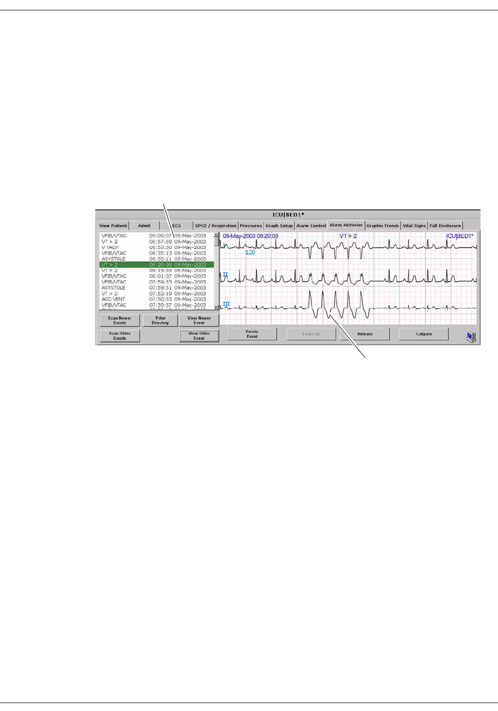
Patient Data: Alarm Histories
Alarm Histories
A patient’s arrhythmia events are stored in Alarm Histories, and can be
reviewed, printed, and deleted at the CIC Pro. To access a patient’s
Alarm Histories tab sheet, follow the instructions below.
1. Click in the bed window of the patient whose Alarm Histories you
wish to view. The CIC Pro display rearranges to accommodate the
single patient viewer at the bottom of the display.
2. In the single patient viewer, click on the Alarm Histories tab,
bringing it to the front.
The Alarm Histories tab sheet contains an event directory (a list of
arrhythmia events recorded) for the patient, and an event window for
viewing individual events. It also contains several buttons, which control
the functions available in Alarm Histories. These functions are described
in this chapter.
Event Directory
Event Window
324D

Revision D ApexPro Telemetry System 10-5
2001989-134
Patient Data: Alarm Histories
Event Directory
An event directory appears on the left side of the Alarm Histories tab.
This directory is a list of all arrhythmia events that have occurred for
this particular patient.
A maximum of 100 events is stored for each patient (36 events in the
Combo monitoring mode). Following are the numbers for each type of
event that can be stored.
20 ST Alarm Histories
1 ST Reference
10 Sample Events (user stored)
100 Arrhythmia Events
After 100 events have been stored, the oldest event is deleted to make
room for any new event that occurs.
Approximately 10 events can be seen in the event directory at one time.
There are two ways to access events that are not currently visible in the
event directory. You can use the mouse and the scroll bar on the right
side of the event directory to scroll up and down through all the events,
or you can use the Scan Newer Events and/or Scan Older Events buttons.
How to use these two buttons is discussed later in this chapter.
Event Window
The event window appears on the right side of the Alarm Histories tab
sheet. The event shown in the event window corresponds to the event
that is highlighted in the event directory. The date, time, and name of
the event are shown in the event window header.
The event window displays 10 seconds of the patient’s ECG waveform
that was recorded when the event occurred. It displays up to three leads
that were being monitored at the time the event occurred. For an ST
event, the alarm ST event is displayed, along with a superimposed ST
template for reference purposes.
To print an event shown in the event window, use the mouse to click on
the Print button in the Main Menu at the bottom of the CIC Pro. One
event is printed per page.

10-6 ApexPro Telemetry System Revision D
2001989-134
Patient Data: Alarm Histories
Alarm Histories Buttons
There are nine buttons that perform various functions in the Alarm
Histories tab. They are described below.
Data Source
This option allows the user to select the specific data source from which
historical patient data can be retrieved (option not shown on figure).
Refer to “Data Source” on page 10-16 for additional information.
Scan Newer Events
Click on the Scan Newer Events button to move through all events in the
event directory that are newer than the event that is currently
highlighted. If there are no events newer than the highlighted event, this
button is dimmed and does not function. This button changes to STOP
when a scan is in process. To stop a scan, click on the button again. While
the scan is in progress, you can also select Scan Older Events to reverse
the scanning direction.
Scan Older Events
Click on the Scan Older Events button to move through all events in the
event directory that are older than the event that is currently
highlighted. If there are no events older than the highlighted event, this
button is dimmed and does not function. This button changes to STOP
when a scan is in process. To stop a scan, click on the button again. While
the scan is in progress, you can also select Scan Newer Events to reverse
the scanning direction.
Print Directory
Click on the Print Directory button to print a list of all events currently
stored in the event directory. The list prints at the Print Window graph
default location.
View Newer Event
Click on the View Newer Event button to view the next newer event
waveforms, if any. If there are no events newer than the highlighted
event, this button is dimmed and does not function.

Revision D ApexPro Telemetry System 10-7
2001989-134
Patient Data: Alarm Histories
View Older Event
Click on the View Older Event button to view the next older event
waveforms, if any. If there are no events older than the highlighted
event, this button is dimmed and does not function.
Delete Event
Click on the Delete Event button to delete the event that is currently
highlighted in the event directory. This cannot be undone.
If more than one event is highlighted (using Shift or Ctrl and the mouse),
a message appears when you press the Delete Event button, asking if you
are sure you wish to delete the events. Click on Ok to continue the delete.
Learn As
The Learn As button is inactive for telemetry patients and appears
dimmed.
Relearn
Select the Relearn button to initiate a relearn procedure. A relearn will
clear the patient’s waveforms and templates, and learn the patient’s
current rhythm as the dominant, “normal” rhythm.
Relearn is useful when you have changed a patient’s electrodes or
leadwires, or when it appears that false alarm calls are being made by
the arrhythmia program. The relearn takes only a few seconds.
Caliper
Select the Caliper button to perform caliper measurements on the ECG
waveform. When selected, the Caliper window opens displaying default
ECG waveform and Calipers which allow you to measure time intervals
for the following waveform measurements: PR, QRS, QT, R-R, and ST.
10-8 ApexPro Telemetry System Revision D
2001989-134
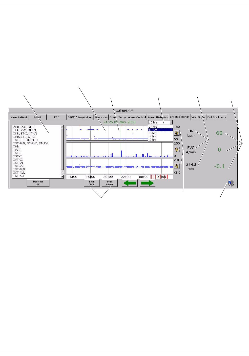
Patient Data: Graphic Trends
Graphic Trends
To view a patient’s graphic trends, follow these steps.
1. Click on the desired patient’s bed window in the multiple patient
viewer. The single patient viewer for that patient opens.
2. Click on the Graphic Trends tab in the single patient viewer. The
Graphic Trends tab sheet moves to the front.
Trend Directory Window
Up to three graphic trend plots can be displayed in the Graphic Trends
window at one time. You can select from preset groupings of trends or
individual trends.
To select the trends for display in the Graphic Trends window, click on a
preset trend grouping or individual trends (up to three). When selected, a
check appears in the box to the left of the label.
Trend Directory
Window
Graphic Trends Window Graphic Trend
Labels
Numeric
Values at the
Cursor
Time Resolution
Menu
Scans Older/Newer
Graphic Trends
Cursor
384C
Indicates PDS Information
is Being Displayed
Scales Trends
Revision D ApexPro Telemetry System 10-9
2001989-134
Patient Data: Graphic Trends
Cursor
One-minute median values can be accessed through the use of a cursor at
the CIC Pro.
The default cursor location is at the current time when entering the
Graphic Trends tab sheet.
You can move the cursor to any median value and review the actual
numeric data.
The cursor is not printed with the graphic trend data.
384C
Cursor
Time and Date Corresponding to
Cursor Position
Arrow Keys Move Cursor
Numeric Values at
the Cursor

10-10 ApexPro Telemetry System Revision D
2001989-134
Patient Data: Graphic Trends
Time Resolution Menu
In the Graphic Trends tab sheet, you can define the amount of trend data
(resolution) to display in the trend window. This is done with the popup
menu located to the right of the time and date.
1. Click on the down arrow to display the time options.
2. Click on the desired time resolution. The time resolution menu
closes, with the selected resolution remaining visible. The selected
time resolution is also reflected immediately in the Graphic Trends
window.
Graphic Trends Buttons
There are six buttons that perform various functions in the Graphic
Trends tab. The function of each button is described below.
Data Source
This option allows the user to select the specific data source from which
historical patient data can be retrieved (option not shown on figure).
Refer to “Data Source” on page 10-16 for additional information.
Deselect All
Click on the Deselect All button to clear all trends from the Graphic
Trends window. Selecting this option also removes any checks from the
Trend Directory window.
385A

Revision D ApexPro Telemetry System 10-11
2001989-134
Patient Data: Graphic Trends
Scan Older
Click on the Scan Older button to initiate a scan of older trend data.
When clicked, the scan begins and older trend data scrolls across the
display. While the scan is in progress, you can select Scan Newer to
reverse the scanning direction.
This button changes to STOP when a scan is in process. Click on the
STOP button to stop a scan in process. When the oldest event is
displayed, the scan automatically stops, and the label on this button will
be dimmed.
Scan Newer
Click on the Scan Newer button to initiate a scan of newer trend data.
When clicked, the scan begins and newer trend data scrolls across the
display. While the scan is in progress, you can select Scan Older to
reverse the scanning direction.
This button changes to STOP when a scan is in process. Click on the
STOP button to stop a scan in process. When the most recent event is
displayed, the scan automatically stops, and the label on this button will
be dimmed.
Arrow Keys
The arrow buttons on the Graphic Trends tab sheet allow you to move
the cursor one minute to the left or right.
Using the left arrow moves the cursor one minute in the “older” direction.
When the oldest (least recent) event is displayed, the left arrow is
dimmed.
Using the right arrow moves the cursor one minute in the “newer”
direction. When the newest (most recent) event is displayed, the right
arrow is dimmed.
040A
10-12 ApexPro Telemetry System Revision D
2001989-134
Patient Data: Graphic Trends
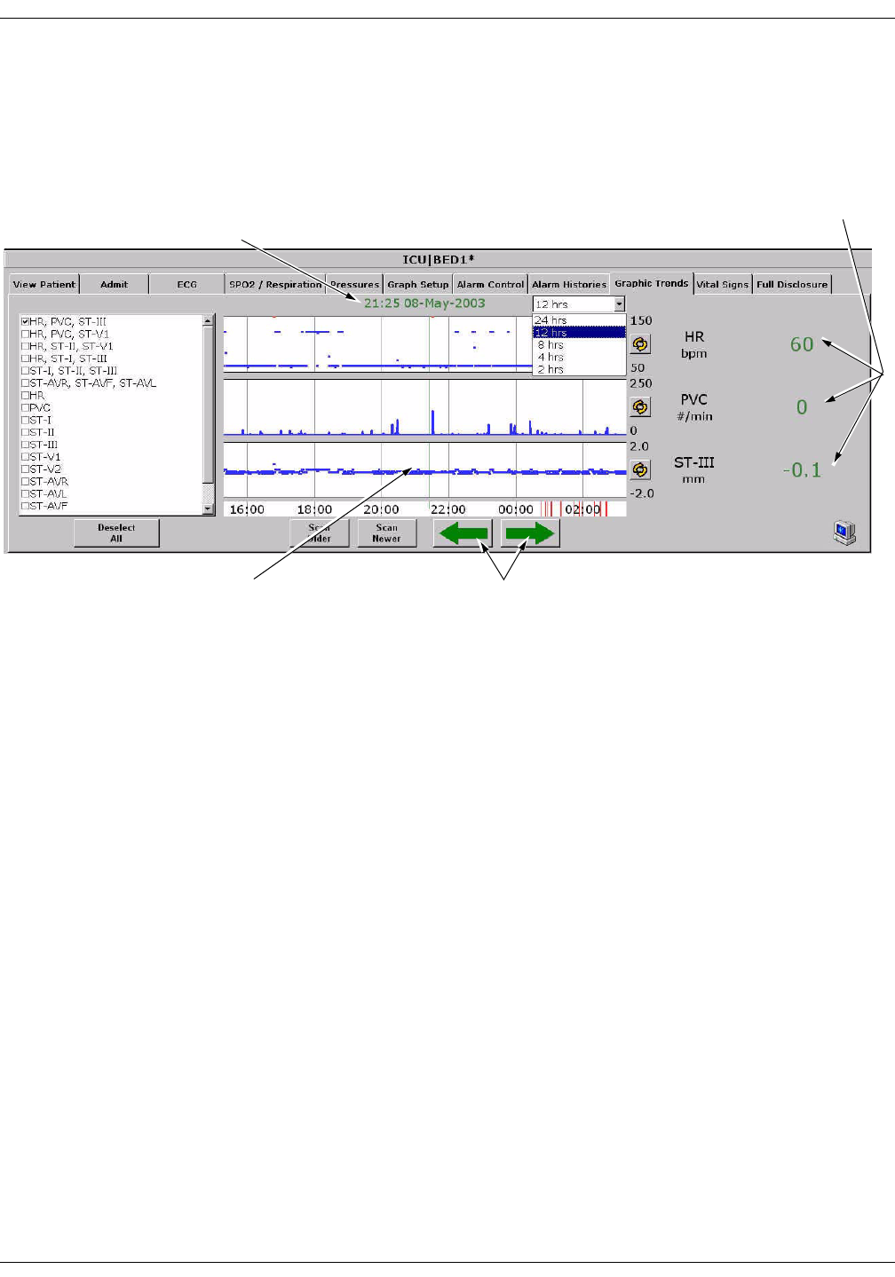
Scalable Trends Key
The Scalable Trends keys allow you to adjust the graphic trend plots.
Selecting this key will scale the trend up or down in preset increments.
For example, the preset scales for HR are:
50–150
0–100
100–200
0–250
PDS Icon
The PDS (Patient Data Server) icon indicates that information has been
archived to the PDS server and is available to be viewed on the Graphic
Trends tab sheet.
If this icon does not appear in the lower right corner of the Graphic
Trends tab sheet, it could mean two things:
The PDS server is not available for retrieving patient information, or
No PDS information has been archived to the PDS server for this
patient.
Printing Graphic Trends
Trends can be printed using the same time scale as the display. To print
a graphic trend, click on the Print button at the bottom of the CIC Pro
display.
Graphic trend printouts for telemetry patients can be printed to a laser
printer or to a writer. Graphic trends print to the Print Window default
printer location.
431A
087A
Revision D ApexPro Telemetry System 10-13
2001989-134
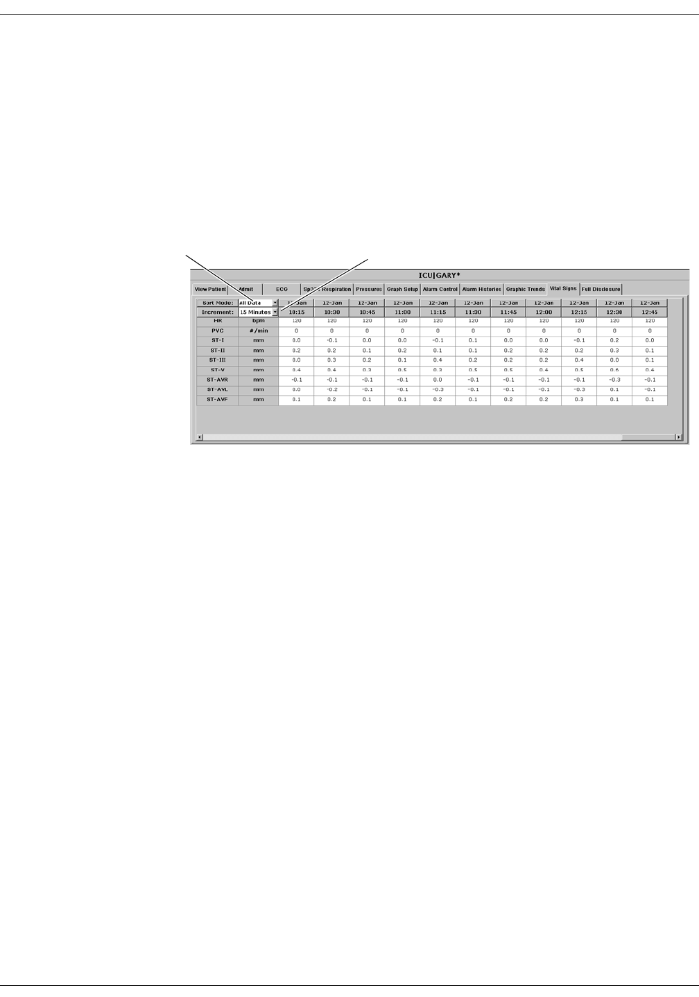
Patient Data: Vital Signs
Vital Signs
To view a patient’s vital signs, follow these steps.
1. Click in the desired patient’s bed window in the multiple patient
viewer. The single patient viewer for that patient opens.
2. Click on the Vital Signs tab in the single patient viewer. The Vital
Signs tab sheet moves to the front. The Vital Signs tab sheet displays
periodic and episodic trend data in tabular, or spreadsheet, form.
NOTE
When a telemetry patient’s vital signs are printed to a Direct Digital
Writer, the anchor column (the column closest to the time interval
selected) and four additional columns print, based on the time
interval selected.
Printed data may be delayed by one minute from the displayed data
due to time of request and update of trend files.
Data Source
This option allows the user to select the specific data source from which
historical patient data can be retrieved (option not shown on figure).
Refer to “Data Source” on page 10-16 for additional information.
Sort Mode Menu Increment Menu
422A
10-14 ApexPro Telemetry System Revision D
2001989-134
Patient Data: Vital Signs
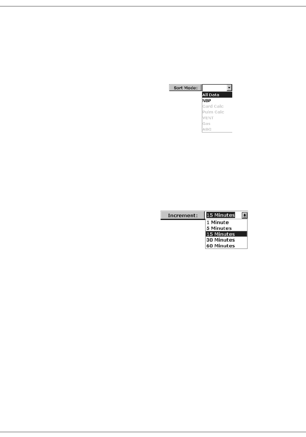
Sort Mode
The Sort Mode popup menu provides options for sorting the way vital
signs data is viewed. If the telemetry patient is being monitored for NBP,
the sort options are All Data and NBP. If the patient is not being
monitored for NBP, the only option available is All Data. All other sort
options appear dimmed.
Increment
In the Vital Signs tab sheet, you can define the amount of data
(resolution) to display in the Vital Signs window. This is done with the
Increment popup menu.
1. Click on the down arrow to display all of the Increment options.
2. Click on the desired increment. The Increment menu closes, with the
selected increment remaining visible. The selected increment is also
reflected immediately in the Vital Signs window.
360A
386A

Revision D ApexPro Telemetry System 10-15
2001989-134
Patient Data: Vital Signs
Scroll Bars
If all of the Vital Signs data does not fit into the available display space,
use the scroll bars to navigate among columns and rows of data. For
more information on using scroll bars, refer to the CIC Pro Clinical
Information Center Operator’s Manual.
Printing Vital Signs
Displayed trends can be printed using the same time scale as the display.
To print a set of vital signs, click on the Print button at the bottom of the
CIC Pro display.
Trends for telemetry patients can be printed to a laser printer or to a
writer. Printing to a writer can only be done in Combo monitoring mode
and must be done from a bedside monitor.

10-16 ApexPro Telemetry System Revision D
2001989-134
Patient Data: Data Source
Data Source
The Data Source option allows the user to select the specific data source
from which historical patient data (Alarm Histories, Graphic Trends, and
Vital Signs) can be retrieved. The Data Source option is only available
when PDS is Enabled (refer to “Telemetry Unit Defaults” on page 6-7).
The Data Source option is labeled Data Source and exists on the left side
of the screen, between the Multi-patient viewer and the Single view
window. Next to this label are two radio buttons that indicate the
possible data sources:
Bedside — This can be either a telemetry or a hardwire bedside. The
amount of historical data is limited to the specific data source. For
most hardwire bedsides, there is a limit of around 32 history events
and 24 hours of trend data.
PDS — This server gathers and stores trend and history events from
hardwire bedsides and telemetry transmitters (refer to the
compatibility list in the Unity Network Patient Data Server (PDS)
Operator’s Manual. Patient data recorded during previous (72 hours)
bedside or telemetry device admissions can be viewed as a single
“patient centric” session. Up to 72 hours of trend data and 500
history events can be stored for a single patient.
The radio button for PDS data source will be disabled in the Alarm
Histories, Graphic Trends and Vital Signs tab sheets for a bedside that is
not being monitored by PDS.
Once the user makes a data source selection for a specific patient, the
setting remains in effect, allowing the user to interact with the data from
the selected data source. Data for printing will be consistent with the
currently selected data source. Selecting a different patient in the multi-
viewer or re-selecting the same patient will automatically change the
data source to be the bedside device.
NOTE
If the operator is on a tab sheet other than Alarm Histories, Graphic
Trends, or Vital Signs, no selection of the data source is possible. For any
application where information needs to be retrieved, such as patient
name, patient ID and alarm control information, the bedside device will
be used.
Data Source: ~Bedside { PDS

Revision D ApexPro Telemetry System 10-17
2001989-134
Patient Data: Time Focus
Time Focus
The CIC Pro has a feature called time focus. When you are viewing one of
the four types of patient data (alarm histories, vital signs, graphic
trends, or full disclosure), time focus allows you to view the other three
types of patient data that were recorded at that same time.
For example, if you are viewing an arrhythmia event in the Alarm
Histories tab that occurred at 1:00 pm, clicking on the Vital Signs tab
would move that tab sheet to the front, with data corresponding to the
time focus (1:00 pm) highlighted. Likewise, if you click on any of the
other patient data tabs, that tab sheet will move to the front, with data
corresponding to the time focus (1:00 pm) at the cursor location.
Since graphic trends are only visible for the period of time specified in
the Graphic Trends tab (refer to the Graphic Trends section in this
chapter for more details), it is possible to view vital signs data, full
disclosure data, or an alarm history event for which the corresponding
graphic trend is no longer stored in the CIC Pro. In this case, clicking on
the Graphic Trends tab takes you to the most recent graphic trend, not
the trend that corresponds to the alarm history, vital signs, or full
disclosure you were viewing.
Alarm histories are episodic events. Therefore, clicking on the Alarm
Histories tab in a time focus situation displays the alarm history event
that occurred closest to the time focus.
10-18 ApexPro Telemetry System Revision D
2001989-134
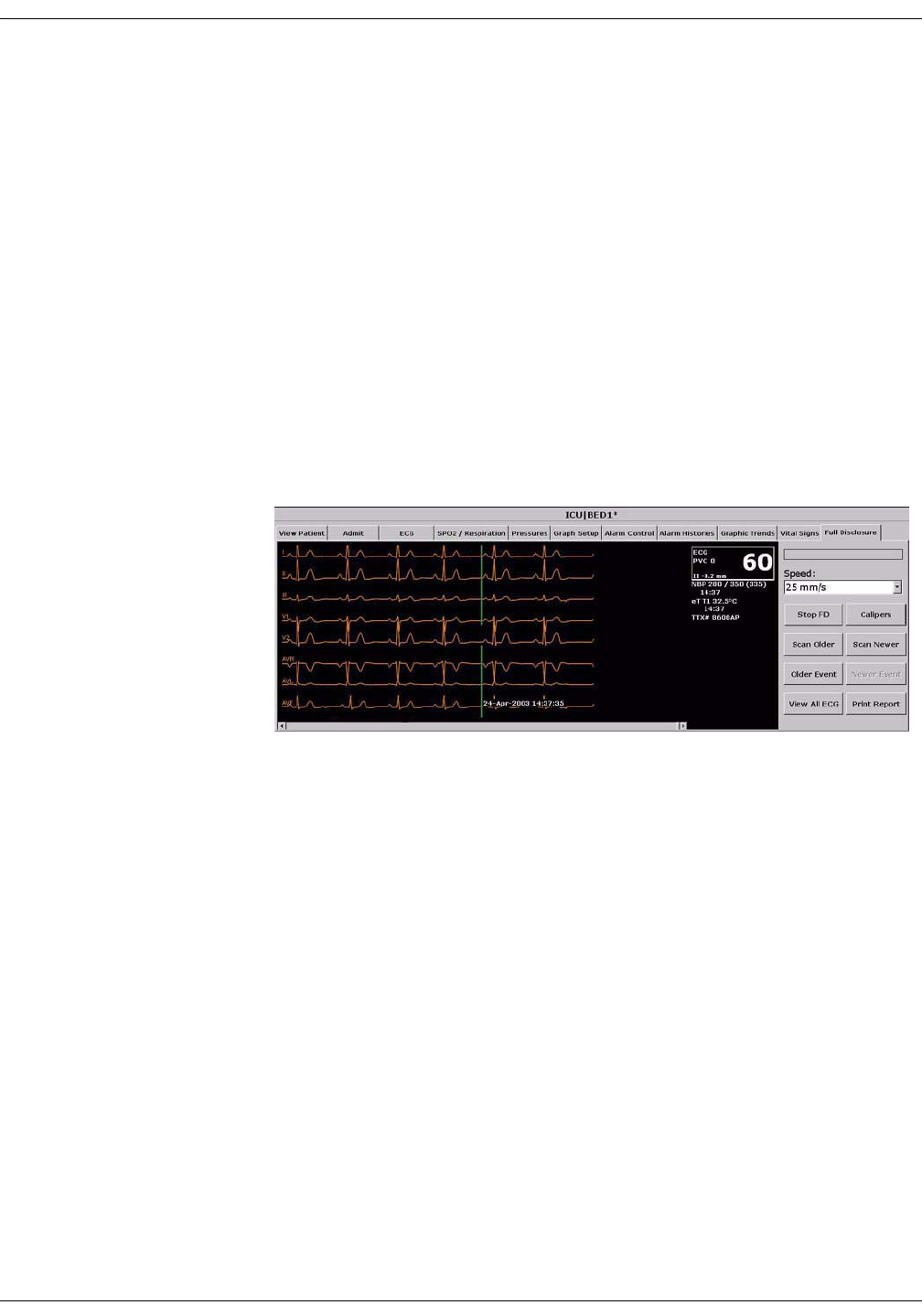
Patient Data: Full Disclosure
Full Disclosure
NOTE
This section provides a brief overview of the Full Disclosure function.
Refer to the CIC Pro Clinical Information Center Operator’s Manual
for detailed information.
The full disclosure feature must be enabled in the Full Disclosure
Defaults tab sheet. Refer to the CIC Pro Clinical Information Center
Operator’s Manual for details on enabling this feature.
When full disclosure is enabled, follow these steps to view a patient’s Full
Disclosure window.
1. Click in the desired patient’s bed window in the multiple patient
viewer. The single patient viewer for that patient opens.
2. Click on the Full Disclosure tab in the single patient viewer. The Full
Disclosure tab sheet moves to the front.
419D

Revision D ApexPro Telemetry System 10-19
2001989-134
Patient Data: Full Disclosure
Full Disclosure Options
Speed
The Speed popup list allows you to set the waveform compression for the
full disclosure waveform display.
Caliper
Select the Caliper button to perform caliper measurements on the ECG
waveform. When selected, the Caliper window opens displaying default
ECG waveform and Calipers which allow you to measure time intervals
for the following waveform measurements: PR, QRS, QT, R-R, and ST.
Stop/Start FD
When Full Disclosure is set for manual mode, this option stops or starts
the Full Disclosure process. If Stop FD is selected, the user is prompted,
"Are you sure you want to stop Full Disclosure?" before Full Disclosure is
stopped.
NOTE
When the Full Disclosure mode is set for automatically if listed or
automatically for all beds, the Stop/Start FD button is hidden.
Scan Older
Clicking on the Scan Older button initiates a scan of older full disclosure
data. When the button is clicked, the scan begins and older trend data
scrolls across the display.
This button changes to STOP when a scan is in process. Click on the
STOP button to stop a scan in process. When the oldest data is displayed,
the scan automatically stops and the label on this button will be dimmed.

10-20 ApexPro Telemetry System Revision D
2001989-134
Patient Data: Full Disclosure
Scan Newer
Clicking on the Scan Newer button initiates a scan of newer full
disclosure data. When the button is clicked, the scan begins and newer
data scrolls across the display.
This button changes to STOP when a scan is in process. Click on the
STOP button to stop a scan in process. When the newest data is
displayed, the scan automatically stops and the label on this button will
be dimmed.
Older Event
Clicking on the Older Event button moves the cursor to the next older
alarm history event.
Newer Event
Clicking on the Newer Event button moves the cursor to the next most
recent alarm history event.
View All ECG/Monitor
This option switches between View All ECG and Monitor. The View All
ECG option displays all ECG waveforms. The Monitor option displays all
waveforms that are displayed at the bedside at the time of full disclosure.
In the case of telemetry patients, these are the same, since only ECG
waveforms are displayed for telemetry patients.
Print Report
Clicking on the Print Report button allows you to set up a report for
printing. In the Print Report window, clicking on Print initiates a full
disclosure report printout. This report prints at the printer designated in
the Full Disclosure Defaults tab sheet.

Revision D ApexPro Telemetry System 11-1
2001989-134
11 ECG Monitoring

11-2 ApexPro Telemetry System Revision D
2001989-134
For your notes

Revision D ApexPro Telemetry System 11-3
2001989-134
ECG Monitoring: Introduction
Introduction
This chapter describes how a telemetry patient’s ECG monitoring
information is displayed at the clinical information center.
Data Synchronization
Information displayed on the ECG tab sheet is synchronized with the
source (ApexPro transmitter) every two seconds. If differences are
detected, the display is refreshed with new information.

11-4 ApexPro Telemetry System Revision D
2001989-134
ECG Monitoring: Patient Preparation
Patient Preparation
The quality of ECG information received and displayed is a direct result
of the quality of the electrical signal at the electrode.
Skin Preparation
Proper skin preparation is necessary for good signal quality at the
electrode.
Choose flat, non-muscular areas to place electrodes, then follow the
established prep protocol for your unit. Following is a suggested
guideline for skin preparation:
1. Shave hair from skin at chosen sites.
2. Gently rub skin surface at sites to remove dead skin cells.
3. Thoroughly cleanse site with a mild soap and water solution. Be sure
to remove all oily residue, dead skin cells, and abrasives. Leftover
abrasion particles can be a source of noise.
4. Allow the skin to dry completely before applying the electrodes.
Electrode Placement
Following is a chart identifying each lead and its associated color code—
AHA and IEC.
Verify Lead Quality and Electrode Status
After the transmitter leads have been properly attached to the patient's
electrodes, verify lead quality and electrode status.
Refer to “ApexPro Transmitter Buttons and LEDs” on page 3-7 for
the ApexPro and ApexPro CH transmitter.
Refer to “LED Indicators Function” on page D-12 for the ApexPro FH
transceiver.
Leadwire
(Software Label) AHA Color AHA Label IEC Color IEC Label
V (precordial) brown V white C
LL (left leg) red LL green F
RL (right leg) green RL black N
LA (left arm) black LA yellow L
RA (right arm) white RA red R
Revision D ApexPro Telemetry System 11-5
2001989-134
ECG Monitoring: Patient Preparation
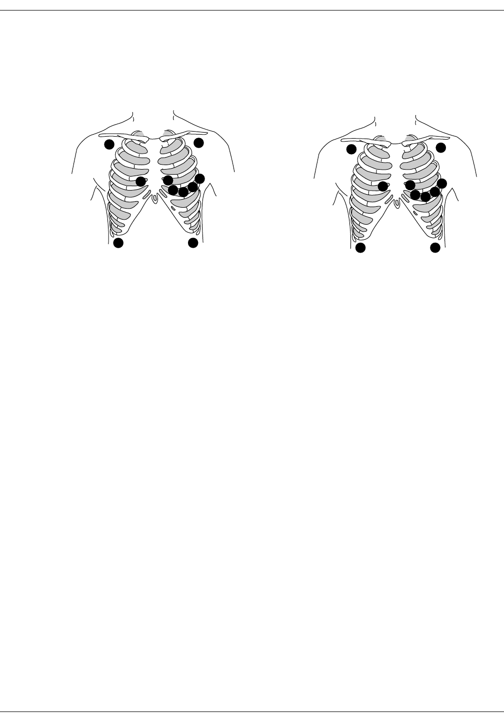
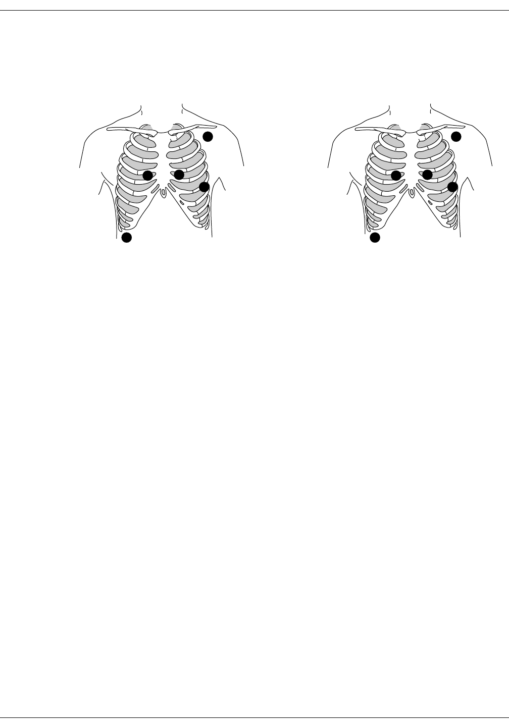
5-Leadwire (Einthoven + V Lead) and 6-Leadwire Electrode Placement
Following are the standard 5- and 6-leadwire electrode configurations for
AHA and IEC:
Right arm and left arm electrodes should be placed just below the right
and left clavicle.
Right leg and left leg electrodes should be placed on a flat non-muscular
surface on the lower edge of the rib cage.
For standard 5-leadwire electrode placement, the chest electrode should
be placed according to the physician’s preference.
For standard 6-leadwire electrode placement, any TWO V leads (chest
electrodes) may be placed according to the physician’s preference.
NOTE
The V1 lead is recommended for arrhythmia detection, and the V5
lead is recommended for ST depression monitoring.*
* Barbara J. Drew, RN, PhD, FAAN (2000). Value of Monitoring a
Second Precordial Lead for Patients in a Telemetry Unit, GE Medical
Systems (order document number M04243ME0).
C1
CL
NF
C2
C3 C4C5
C6
V1
RA LA
RL LL
V2
V3 V4 V5
V6
AHA Configuration IEC Configuration
368B 372B
11-6 ApexPro Telemetry System Revision D
2001989-134
ECG Monitoring: Patient Preparation
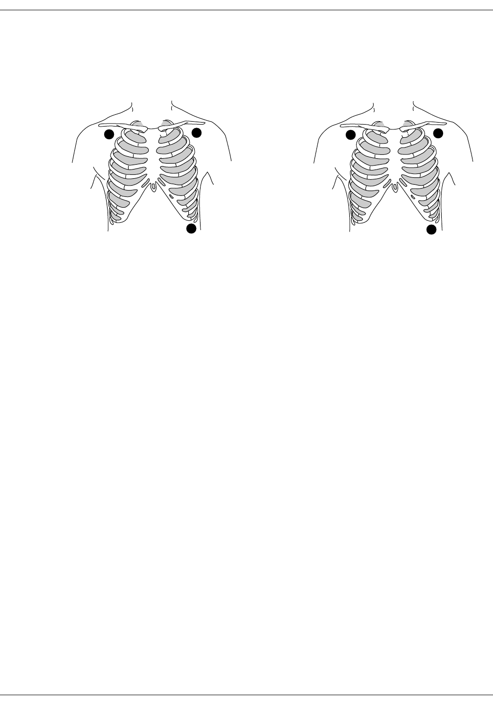
3-Leadwire Electrode Placement
When a 5-leadwire electrode configuration is not desirable, a 3-leadwire
cable can be used.
NOTE
Electrode configuration will vary depending on the type of leadwire
set you are using.
Right arm and left arm electrodes should be placed just below the right
and left clavicle.
Left leg electrode should be placed on a non-muscular surface on the
lower edge of the rib cage.
Electrode Placement for Pediatric Patients
Typically, pediatric patients are large enough for a 5- or 6-leadwire
electrode configuration. This is the preferred monitoring setup for
receiving the benefits of multi-lead analysis. However, if the patient is
too small for five or six electrodes, the 3-leadwire electrode configuration
can be used. The right arm and left arm electrodes are positioned on the
right and left sides of the chest. The right leg electrode can be placed on
either the right or left side of the abdomen. Refer to the illustrations in
the 3-Leadwire Electrode Placement section above.
RL
F
RA LA
LL
3-Leadwire AHA Configuration 3-Leadwire IEC Configuration
370A 373A
Revision D ApexPro Telemetry System 11-7
2001989-134
ECG Monitoring: Patient Preparation
Modified Chest Lead (MCL) Electrode Placement
Following is the modified chest lead (MCL) electrode configuration with
the associated location:
Right arm electrode should be placed in the fourth intercostal space to
the right of the sternum.
Left arm electrode should be placed just below the left clavicle.
Left leg electrode should be placed in the sixth intercostal space along
the mid-axillary line.
Right leg electrode should be placed on a flat non-muscular surface on
the lower edge of the rib cage.
R
L
C1
F
N
RA
LA
V1
LL
RL
AHA Configuration
MCL Electrode Placement
IEC Configuration
MCL Electrode Placement
371A 375A
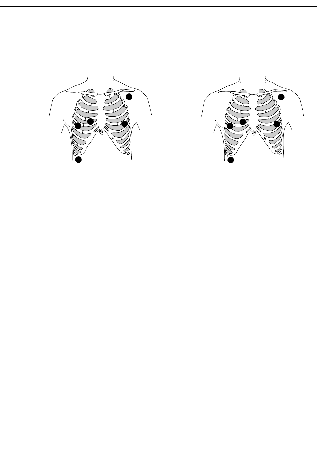
11-8 ApexPro Telemetry System Revision D
2001989-134
ECG Monitoring: Patient Preparation
Electrode Placement for Pacemaker Patients
Electrodes need to be repositioned to modify detection of the electrical
signals generated by the pacemaker. Following is a suggested
configuration:
The right arm electrode is moved down to the fifth intercostal space, and
the left leg electrode is moved up to the fifth intercostal space.
NOTE
After all electrodes are in place, ensure that a minimum of 1/2 mV of
signal is present on each lead (I, II, III, V).
L
C1
RF
N
RA
LA
V1 LL
RL
AHA Configuration
Pacemaker Electrode Configuration
IEC Configuration
Pacemaker Electrode Configuration
369A 374A

Revision D ApexPro Telemetry System 11-9
2001989-134
ECG Monitoring: Patient Preparation
Maintaining Quality ECG Signal
Regardless of patient type, electrodes should be replaced at least every
48 hours to maintain quality signals during long-term monitoring. Over
the course of 48 hours, the electrode gel will start to dry out and the
adhesive will age. This may irritate the patient’s skin.
Stabilize the electrode and leadwire with a leadwire stress loop near the
electrode. Tape the stress loop to the patient. A secured stress loop
prevents leadwire rotation about the electrode snap, leadwire tugging at
the electrode, and ECG artifact.
Stress Loop
306A

11-10 ApexPro Telemetry System Revision D
2001989-134
ECG Monitoring: Special Considerations for 6-Lead Monitoring
Special Considerations for 6-Lead Monitoring
V FAIL Message
CAUTION
The clinical information center does not detect 6-lead
monitoring until a signal from the sixth lead is received
at the clinical information center. Therefore, if the sixth
lead on the ApexPro transmitter has failed before the
telemetry patient is admitted to the clinical information
center, the clinical information center will NOT generate
a V FAIL message for the sixth lead.
At the patient’s ApexPro transmitter, verify that the sixth lead on the
ApexPro transmitter is good. Press the Verify Leads button on the
ApexPro transmitter and ensure that all the good lead LEDs illuminate.
(Refer to Chapter 3, Equipment Overview, for button and LED locations.)
Relearn
If a telemetry patient is switched from 6-lead monitoring to 5-lead
monitoring while ADMITTED to the clinical information center, a V
FAIL message will appear. The clinical information center “assumes”
that the telemetry patient is being monitored for six leads and that the
sixth lead has failed.
In situations where the admitted telemetry patient has been switched
from 6- to 5-lead monitoring, the associated V FAIL message can be
cleared by clicking on the Relearn button in the telemetry patient’s ECG
tab sheet. (Refer to the ECG Tab Sheet section in this chapter for
information about the Relearn button.)
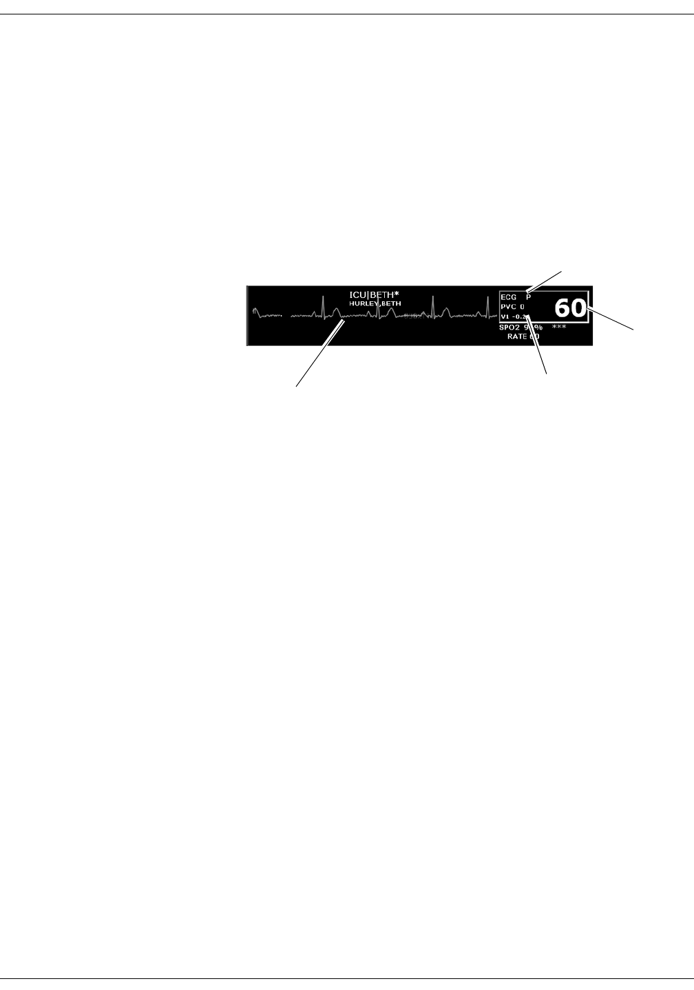
Revision D ApexPro Telemetry System 11-11
2001989-134
ECG Monitoring: ECG Monitoring
ECG Monitoring
ECG in the Multiple Patient Viewer
For telemetry patients, up to four leads of ECG can be displayed in the
bed window of the multiple patient viewer. Also displayed are the
patient’s heart rate, current PVC per minute value, ST analysis, and a
“P” if pace detection is turned on. Below is an example of a telemetry
patient’s bed window in the multiple patient viewer.
Heart rate
Indicates pace
detection is on
ST analysis
ECG waveform
346B
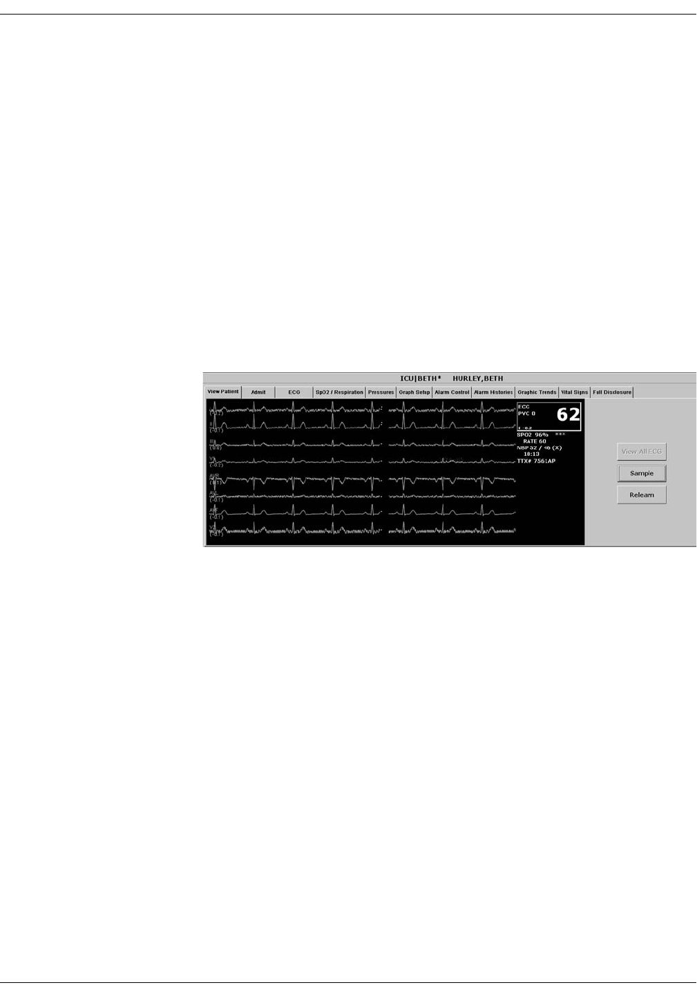
11-12 ApexPro Telemetry System Revision D
2001989-134
ECG Monitoring: ECG Monitoring
ECG in the Single Patient Viewer
View Patient Tab Sheet
For telemetry patients, up to eight leads of ECG can be seen in the View
Patient tab sheet. It is also possible to sample ten seconds of ECG data
for storage in Alarm Histories, and to initiate a relearn of the patient’s
rhythm. The patient’s heart rate, current PVC per minute value, ST
information, and “P” for pace detection (if turned on) are also displayed.
To access the View Patient tab sheet, follow the steps below.
1. Click in the desired patient’s bed window in the multiple patient
viewer. The display rearranges to accommodate the single patient
viewer for that patient.
2. If it is not already visible at the front of the tabs, click on the View
Patient tab to bring the tab sheet to the front.
For more details about the features and functions of the View Patient tab
sheet, refer to Chapter 7, Admit/View a Patient, in this manual.
348D

Revision D ApexPro Telemetry System 11-13
2001989-134
ECG Monitoring: ECG Monitoring
Full Disclosure Tab Sheet
When you purchase the appropriate Full Disclosure licenses, you can
acquire either 24-hours or 72-hours of Full Disclosure data per bed
license. If full disclosure is turned on, data can be viewed in the Full
Disclosure tab sheet.
To access the Full Disclosure tab sheet, follow the steps below.
1. Click in the desired patient’s bed window in the multiple patient
viewer. The display rearranges to accommodate the single patient
viewer for that patient.
2. Click on the Full Disclosure tab to bring the tab sheet to the front.
For more details about the features and functions of the Full Disclosure
tab sheet, refer to the CIC Pro Clinical Information Center Operator’s
Manual.
ECG Limits
You can adjust the alarm limits for ECG (such as HR, ST, etc.) in the
Telemetry Alarm Control Defaults tab and in the patient’s Alarm Control
tab. For more information on how to set the alarm limits, refer to
Chapter 8, Alarm Control, in this manual.

11-14 ApexPro Telemetry System Revision D
2001989-134
ECG Monitoring: ECG Monitoring
ECG Artifact
The clinical information center has two levels for artifact alarms.
Level 1 artifact displays the ARTIFACT message, but continues to
display a heart rate.
The ARTIFACT message does not flash or generate an audible
alarm.
The ARTIFACT message will be relocated to the lead fail area of
the display.
If the patient is in a lead fail, the lead fail message has priority
over the ARTIFACT message on the display.
Level 2 artifact displays the ARTIFACT message, but the heart rate
values are removed from the display.
The ARR SUSPEND message is a System Status Alarm and can
be set at Warning, Advisory, or Message level.
The clinical information center displays the ARR SUSPEND
message when it is determined that the arrhythmia is in the
level 2 ARTIFACT state.
The ARR SUSPEND message is displayed in the Arrhythmia
event line and, if set at Warning or Advisory level, is sent to the
ADU line for alarm notification.
For more information about alarms, refer to Chapter 8, Alarm Control, in
this manual.
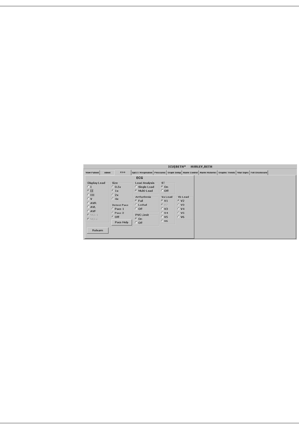
Revision D ApexPro Telemetry System 11-15
2001989-134
ECG Monitoring: ECG Tab Sheet
ECG Tab Sheet
The ECG tab sheet allows you to view and modify settings specific to the
viewed patient’s ECG display. Settings may be viewed for any patient.
However, you can only modify settings for patients who are admitted to a
bed in your care unit.
Accessing the ECG Tab Sheet
To access a patient’s ECG tab sheet in the single patient viewer, follow
this procedure:
1. Click in the desired patient’s bed window in the multiple patient
viewer. The display rearranges to accommodate the single patient
viewer for that patient.
2. Click on the ECG tab in the single patient viewer. The ECG tab sheet
moves to the front.
302A

11-16 ApexPro Telemetry System Revision D
2001989-134
ECG Monitoring: ECG Tab Sheet
Display Lead
This option allows you to change the lead currently displayed as the
primary lead. Use the mouse to click on your Display Lead selection.
Relearn
Clicking on the Relearn button initiates a relearn of the patient’s ECG
rhythm. The relearn takes only a few seconds. The patient’s heart rate
reading is momentarily replaced by Xs. Numerics return once the relearn
is complete.
You should use the relearn function whenever there has been a
significant change in the patient’s rhythm.
Size
This option allows you to change the size of the ECG waveforms
displayed at the clinical information center. This may be necessary when
diagnosing or problem solving. Normal size (1x) is recommended unless
circumstances require otherwise.
To change the waveform display size, use the mouse to click on an option.
NOTE
If a size other than 1x is used, the size is displayed on the left side of
the screen next to the ECG waveform.

Revision D ApexPro Telemetry System 11-17
2001989-134
ECG Monitoring: ECG Tab Sheet
Detect Pace
Safety Considerations
Be aware of the following when monitoring a patient with a pacemaker.
WARNINGS
FALSE CALLS—False low heart rate indicators or false
asystole calls may result with certain pacemakers
because of electrical overshoot.
MONITORING PACEMAKER PATIENTS—Monitoring
of pacemaker patients can only occur with the pace
program activated.
PACEMAKER SPIKE—An artificial pacemaker spike is
displayed in place of the actual pacemaker spike. All
pacemaker spikes appear uniform. Do not diagnostically
interpret pacemaker spike size and shape.
PATIENT HAZARD—A pacemaker pulse can be counted
as a QRS during asystole in either pace mode. Keep
pacemaker patients under close observation.
RATE METERS—Keep pacemaker patients under close
observation. Rate meters may continue to count the
pacemaker rate during cardiac arrest and some
arrhythmias. Therefore, do not rely entirely on rate
meter alarms.

11-18 ApexPro Telemetry System Revision D
2001989-134
ECG Monitoring: ECG Tab Sheet
CAUTION
FDA POSTMARKET SAFETY ALERT—The United
States FDA Center for Devices and Radiological Health
issued a safety bulletin October 14, 1998. This bulletin
states “that minute ventilation rate-adaptive
implantable pacemakers can occasionally interact with
certain cardiac monitoring and diagnostic equipment,
causing the pacemakers to pace at their maximum
programmed rate.”
The FDA further recommends precautions to take into
consideration for patients with these types of
pacemakers. These precautions include disabling the rate
responsive mode and enabling an alternate pace mode.
For more information contact:
Office of Surveillance and Biometrics, CDRH, FDA
1350 Piccard Drive, Mail Stop HFZ-510
Rockville, MD 20850
U.S.A.
NOTE
ECG monitoring with patients on non-invasive transcutaneous
pacemakers may not be possible due to large amounts of energy
produced by these devices. Monitoring ECG with an external device
may be needed.

Revision D ApexPro Telemetry System 11-19
2001989-134
ECG Monitoring: ECG Tab Sheet
Monitoring Pacemaker Patients
The Detect Pace option enables/disables the pacemaker detection
program. It must be used whenever the monitored patient has a
pacemaker. Pace detection choices are Pace 1 and Pace 2. You can also
choose to turn pace detection Off. Use the mouse to click on a Detect Pace
selection.
NOTE
The Off option turns pacemaker detection off. It does NOT perform
pacemaker detection. Either the Pace 2 or Pace 1 option MUST be
used with patients who have pacemakers.
There are two pacemaker processing modes, Pace 1 and Pace 2. The Pace
1 and Pace 2 modes use different algorithms for pacemaker artifact
rejection. The clinician must be the judge as to which mode is better for
each patient. The pacemaker detection program defaults off so if you
have a patient with a pacemaker, you will have to turn the program on.
The Pace 2 mode is much more conservative in recognizing paced QRS
morphologies and is recommended for use whenever possible. It is
designed to minimize the possibility of counting pacemaker artifact as
QRS complexes during ASYSTOLE. If the monitor does not adequately
detect paced beats in the Pace 2 mode, then the user may wish to try the
Pace 1 mode.
NOTE
Please observe all cautions as described when choosing the Pace 1
mode of operation.
The Pace 1 mode allows successful detection of the largest variety of
paced QRS morphologies. As a direct consequence, this mode does have a
higher risk of counting pacemaker artifact as QRS complexes during
ASYSTOLE. For this reason, it is imperative that the user keep patients
with pacemakers under close observation. It is also recommended that
the user set the low heart rate limit on the monitor close to the minimum
pacing rate, and that the BRADY arrhythmia alarm level be elevated to a
WARNING or CRISIS level.
When either pace mode is enabled, the software places an artificial spike
on the waveform whenever the pacemaker triggers. When pacemaker
detection is on, it is indicated by a “P” in the patient’s ECG parameter
window.

11-20 ApexPro Telemetry System Revision D
2001989-134
ECG Monitoring: ECG Tab Sheet
For successful monitoring of pacemaker patients follow these
suggestions:
Use recommended electrode placement.
Brady, Pause, and Low Heart Rate are additional alarms available
for use when monitoring pacemaker patients.
Problems you may experience are:
heart rate double counting;
inaccurate alarms for low heart rate or asystole;
pacemaker spikes not recognized by the software.
Possible solutions to above problems are:
relearn arrhythmia;
try an alternate electrode placement;
try single-lead analysis;
try switching to the other pace detection mode.
Pacemaker mode:
In most cases, Pace 2 mode will effectively monitor a pacemaker
patient. However, if you are experiencing problems, select the Pace 1
mode as an option, and observe all cautions as described for the
Pace 1 mode of operation.
Multi-Vector Pace Detection (ApexPro CH only)
NOTE
The ApexPro CH transmitter is not for sale outside of the U.S. and
Canada.
The ApexPro CH transmitter uses multi-vector pace detection. Here are
some additional guidelines for successful monitoring pacemaker patients
when using the ApexPro CH transmitter.
When using the 5 or 6-leadwire patient cable with all the electrodes
attached, pace detection occurs on two ECG leads simultaneously.
The default leads used for detection are II and V. If these leads are
not available, multi-vector pace detection switches to available leads.
Pace detection switches to single-lead when using a 3-leadwire
patient cable.
For more information, refer to the Pacemaker Troubleshooting section in
this chapter.
Revision D ApexPro Telemetry System 11-21
2001989-134
ECG Monitoring: ECG Tab Sheet
Pace Help
Clicking on the Pace Help button opens a window that shows common
problems and solutions in regard to pacemaker detection. This window is
shown below.
047A

11-22 ApexPro Telemetry System Revision D
2001989-134
ECG Monitoring: ECG Tab Sheet
Lead Analysis
The Lead Analysis control signals the ApexPro transmitter to process the
ECG in Single Lead or Multi-Lead mode. Use the mouse to click on your
selection. Multi-lead analysis is the default setting for adults.
Multi-Lead Analysis
Multi-lead analysis simultaneously examines ECG leads I, II, III, and V
(whether they are displayed or not) to help eliminate false alarms and
improve the ability of the system to:
Detect beats which occur isoelectric to a single chest lead.
Discriminate artifact that appears in one lead compared to the other
lead vectors.
Provide a “smart-lead fail” feature, where the failed lead is identified,
and if available, another lead is provided for display.
Continue arrhythmia processing even after a lead change.
Single Lead Analysis
Single lead analysis uses only the lead displayed on the clinical
information center screen to process ECG and arrhythmia information.
To change the lead used for single lead analysis, you must change the
displayed lead.
Single lead analysis is beneficial when troubleshooting pacemaker
detection and/or arrhythmia detection. Single lead analysis must always
be used when monitoring with a 3-lead cable. Single lead analysis can be
set up as a unit default. Refer to Chapter 6, Telemetry Setup, for more
information.

Revision D ApexPro Telemetry System 11-23
2001989-134
ECG Monitoring: ECG Tab Sheet
Single Lead ECG Telemetry Data
NOTE
When acquiring Single Lead ECG data using a 5-leadwire or 6-
leadwire cable, it is NOT necessary to connect the V leads or the
right leg lead to the transmitter or to the patient.
The following constraints apply when using Single Lead ECG telemetry
data.
Function Single Lead Constraints
change the displayed
lead
The factory default display lead is lead II.
Contact your local service representative to change the
default displayed lead.
Display Lead appears to be selectable at the CIC Pro.
However, your selection is temporary and will revert back
to the ApexPro transmitter’s default displayed lead.
NOTE
When the clinical situation dictates
monitoring a lead other than the default
lead, you can move the leads and/or
electrodes to view a different lead. Be aware
that the label on the display and on the
printout will show the default lead label.
lead analysis Multi-Lead analysis may appear to be selectable at the CIC
Pro. However, your selection is temporary and will revert
back to the Single Lead analysis mode.
select a V lead V leads may appear to be selectable at the CIC Pro.
However, your selection does not change the ApexPro
transmitter’s default displayed lead.
select displayed leads
from a single viewer
Leads other than the default displayed lead may appear to
be selectable at the CIC Pro. However, your selection is
temporary and will revert back to the ApexPro transmitter’s
default displayed lead.
select graph waveforms Leads other than the default displayed lead may appear to
be selectable at the CIC Pro. However, you must select the
ApexPro transmitter’s default displayed lead to obtain a
graph of the waveform.

11-24 ApexPro Telemetry System Revision D
2001989-134
ECG Monitoring: ECG Tab Sheet
Arrhythmia
NOTE
Full arrhythmia processing is
suspended when the level 1
“ARTIFACT” message is
displayed. Lethal arrhythmia is
still active but its accuracy may be
hindered by the artifact.
WARNINGS
SUSPENDED ANALYSIS—Certain conditions suspend
arrhythmia analysis. When suspended, arrhythmia
conditions are not detected and alarms associated with
arrhythmias do not occur. The messages which alert you
to the conditions causing suspended arrhythmia analysis
are: ALL ALARMS OFF, ALARM PAUSE, ARR OFF,
ARR SUSPEND, DISCHARGED, LEADS FAIL, and NO
TELEM. Additionally, the alarms off with reason options
and disabling the alarm pause breakthrough feature also
suspend arrhythmia analysis.
VENTRICULAR ARRHYTHMIAS—The arrhythmia
analysis program is intended to detect ventricular
arrhythmias. It is not designed to detect atrial or
supraventricular arrhythmias. Occasionally it may
incorrectly identify the presence or absence of an
arrhythmia. Therefore, a physician must analyze the
arrhythmia information in conjunction with other clinical
findings.
The arrhythmia control signals the clinical information center to ignore
or accept arrhythmia calls. To modify arrhythmia settings, use the
mouse to click on Full, Lethal, or Off.
NOTE
When arrhythmia program is in Full mode, the program counts the
number of PVCs that occur within a minute.
Turning arrhythmia on automatically starts a relearn procedure.
When arrhythmia is turned off, ARR OFF appears in the ECG
parameter window.

Revision D ApexPro Telemetry System 11-25
2001989-134
ECG Monitoring: ECG Tab Sheet
No Arrhythmia Detection with Patient Monitors at 7015 Software Level
If an ApexPro telemetry system patient is admitted to a patient monitor
at the 7015 software level (ECG source is telemetry, not the monitor), the
following scenario may occur when monitoring in Combo or Rover/Combo
monitoring modes:
Since the 7015 software level does not support arrhythmia
processing, arrhythmia detection for the telemetry patient is reduced
from full arrhythmia detection to no arrhythmia detection
(arrhythmia OFF). This occurs because the software is designed to
take on the attributes of the bedside monitor when in Combo or
Rover Combo monitoring modes.
CAUTION
Under these conditions, arrhythmia detection is OFF.
There is NO INDICATION of this at the bedside monitor,
central station or clinical information center.
If the patient is later discharged from the monitor, and monitoring
continues from telemetry, the message ARR OFF will then appear at
the central station or clinical information center. Arrhythmia
monitoring remains OFF.
NOTE
Solar 7000 monitors, Solar 8000 monitors, Dash monitors, and Eagle
monitors may include the 7015 software level.

11-26 ApexPro Telemetry System Revision D
2001989-134
ECG Monitoring: ECG Tab Sheet
Full Arrhythmia Conditions
Below is an alphabetical list of the arrhythmia messages that are
displayed when full arrhythmia is selected and the condition occurs.
Definitions of each condition are included. The CIC Pro’s response to
each condition is determined by the alarm level to which the arrhythmia
has been assigned.
ACC VENT Adult—Accelerated ventricular occurs when six or more
ventricular beats are detected with an average heart rate for
the ventricular beat between 50 and 100 beats per minute.
0-2 years—Occurs when six or more ventricular beats are
detected with an average heart rate for the ventricular beat
between 60 and 160 beats per minute.
3-10 years—Occurs when six or more ventricular beats are
detected with an average heart rate for the ventricular beat
between 60 and 140 beats per minute.
11-13 years—Occurs when six or more ventricular beats are
detected with an average heart rate for the ventricular beat
between 60 and 130 beats per minute.
ASYSTOLE Ventricular asystole occurs whenever the displayed heart rate
drops to zero.
BIGEMINY Occurs when three or more bigeminal cycles (a ventricular
beat followed by a non-ventricular beat) are detected.
BRADY Bradycardia is the average of the most recent eight R-to-R
intervals at a heart rate less than the set LOW heart rate limit.
NOTE
The Brady limit matches the low heart rate
limit. If the low heart rate limit is changed,
the Brady limit changes.
COUPLET Occurs when two ventricular beats are detected and have non-
ventricular beats before and after the couplet. The coupling
interval must be less than 600 milliseconds.
IRREGULAR Occurs when six consecutive normal R-to-R intervals vary by
100 milliseconds or more.

Revision D ApexPro Telemetry System 11-27
2001989-134
ECG Monitoring: ECG Tab Sheet
WARNING
VFIB/VTAC should not be considered a substitute for
the V TACH arrhythmia call. Efforts to lower the V
TACH alarm level can result in missed ventricular
tachycardia alarms.
PAUSE Occurs when a 3-second interval without a QRS complex is
detected.
PVC Isolated premature ventricular complexes occur when a
premature ventricular beat is detected and has non-ventricular
beats before and after.
R ON T Occurs when a ventricular complex is detected within the
repolarization period of a non-ventricular beat.
TACHY Tachycardia is four R-to-R intervals at a heart rate greater than
the set HIGH heart rate limit.
NOTE
The Tachy limit matches the high heart rate
limit. If the high heart rate limit is changed,
the Tachy limit changes.
TRIGEMINY Occurs when three or more trigeminal cycles (a ventricular
beat followed by two non-ventricular beats) are detected.
V BRADY Adult—Ventricular bradycardia occurs when a run of three or
more ventricular beats is detected with an average heart rate
that is less than or equal to 50 beats per minute.
0-2, 3-10, and 11-13 years—Occurs when a run of three or
more ventricular beats is detected with an average heart rate
that is less than or equal to 60 beats per minute.
VFIB/ VTAC Ventricular fibrillation occurs when the ECG waveform
indicates a chaotic ventricular rhythm.

11-28 ApexPro Telemetry System Revision D
2001989-134
ECG Monitoring: ECG Tab Sheet
V TACH Adult—Ventricular tachycardia occurs when a run of six or
more ventricular beats is detected with an average heart rate
greater than or equal to 100 beats per minute.
0-2 years—Occurs when a run of six or more ventricular beats
is detected with an average heart rate greater than or equal to
160 beats per minute.
3-10 years—Occurs when a run of six or more ventricular
beats is detected with an average heart rate greater than or
equal to 140 beats per minute.
11-13 years—Occurs when a run of six or more ventricular
beats is detected with an average heart rate greater than or
equal to 130 beats per minute.
VT > 2 Adult—Ventricular tachycardia >2 occurs when a run of
ventricular beats is detected with a duration of less than six
beats but longer than two beats and with an average heart rate
that is greater than or equal to 100 beats per minute.
0-2 years—Occurs when a run of ventricular beats is detected
with a duration of less than six beats but longer than two beats
and with an average heart rate that is greater than or equal to
160 beats per minute.
3-10 years—Occurs when a run of ventricular beats is
detected with a duration of less than six beats but longer than
two beats and with an average heart rate that is greater than or
equal to 140 beats per minute.
11-13 years—Occurs when a run of ventricular beats is
detected with a duration of less than six beats but longer than
two beats and with an average heart rate that is greater than or
equal to 130 beats per minute.

Revision D ApexPro Telemetry System 11-29
2001989-134
ECG Monitoring: ECG Tab Sheet
Lethal Arrhythmia Conditions
When Lethal arrhythmia is selected, the following conditions (as defined
for Full arrhythmia) are detected:
ASYSTOLE
VFIB/VTAC
V TACH (defaults to the Crisis level, but can be moved to a different
level)
BRADY (if the patient age range selected is 0-2 years or 3-10 years)
PVC Limit
When on, the PVC Limit control displays a PVC counter in the ECG
parameter window. When off, the PVC counter is not displayed. Use the
mouse to turn the PVC Limit control On or Off.
The PVC limits are preset in Alarm Control defaults. For more
information on setting the limits, refer to Chapter 8, Alarm Control, in
this manual.
ST
The ST control turns the display of ST segment analysis data on and off.
Use the mouse to turn ST segment analysis On or Off. For more
information about ST analysis, refer to the ST Analysis section in this
chapter.
Va Lead and Vb Lead
Correctly labelling V leads is important to facilitate correct ECG analysis
when viewing real time waveforms, histories or printouts. These two
option lists allows you to label the V leads. Use the mouse to click on your
Va Lead and Vb Lead selections.
NOTE
Vb Lead selections are only available with 6-lead monitoring.

11-30 ApexPro Telemetry System Revision D
2001989-134
ECG Monitoring: ECG Tab Sheet
AFIB Identification
Atrial fibrillation (AFIB) is characterized by random, chaotic, low-
amplitude deflections of the supraventricular component of the ECG
waveform, resulting in irregular timing of QRS complexes and an
absence of uniform P waves preceding the QRS complex.
The AFIB algorithm feature identifies atrial fibrillation arrhythmias for
the ApexPro transmitter. When the AFIB arrhythmia detection feature
is selected, it replaces the IRREGULAR arrhythmia alarm text with the
ATRIAL FIB alarm text.
Alarms
A patient status alarm is triggered when an AFIB arrhythmia is
detected. The message ATRIAL FIB is displayed in the message area of
the display.
NOTE
There is approximately a 90 second delay while the AFIB algorithm
verifies the AFIB arrhythmia condition.
The AFIB alarm defaults to a MESSAGE alarm level but can be changed
under Arrhythmia Alarm Level, in the Telemetry Alarm Control
Defaults tab sheet on the CIC Pro. How the monitor responds to each
condition is determined by the alarm level to which the AFIB arrhythmia
detection has been assigned. When set for Advisory or greater, AFIB
alarms will be recorded and displayed in the alarm area on the CIC Pro.
Alarm Limitations
Some bedside monitors do not support atrial fibrillation. When the
ApexPro telemetry system is used in combo monitoring mode with a
monitor that does not support atrial fibrillation, there may be alarm
limitations.
Following is a list of alarm limitations:
No AFIB message in the CIC Pro single/multi-viewer window or at
the bedside monitor.
No alarms broadcasted to other CIC Pro’s
No alarm text on the graph header
Instead of AFIB, a question mark (?) is displayed in Alarm History

Revision D ApexPro Telemetry System 11-31
2001989-134
ECG Monitoring: ST Analysis
ST Analysis
The patient’s most dominant, normal beat is used for ST measurement.
This beat is identified by the arrhythmia analysis program. Turn ST on
to display the numerics calculated for ST at the clinical information
center.
GE Medical Systems Information Technologies identifies the ST segment
of the QRS complex as beginning at the J point and ending 60
milliseconds following the J point. The ST numeric displayed
(millimeters) indicates either a positive or negative elevation in relation
to the isoelectric reference point (which is also determined by the
arrhythmia program and the patient’s age).
When ST is on, numerics are displayed under each ECG lead label on the
screen. (A negative deflection is preceded by a minus sign.) These
numerics are updated about every 15 seconds.
The ST value shown in the ECG parameter window is the lead with the
greatest ST deviation. This may or may not be the lead that is in alarm,
since a lead with a lesser deviation from the isoelectric line may have
changed more than the lead with the greatest deviation.
NOTE
ST numerics are always calculated with reference to 1X size.
Displaying the ECG waveform at a different size does NOT affect the
ST values.
NOTE
When a new dominant beat is detected or a relearn occurs, the
arrhythmia program calculates ST based on the new beat. This could
affect the ST values displayed. This may not necessarily represent a
change in the patient’s condition. The clinician needs to assess the
patient any time there is an ST change.

11-32 ApexPro Telemetry System Revision D
2001989-134
ECG Monitoring: ST Analysis
ST Deviation Alarm
When any individual ST value is beyond the limit, an ST deviation alarm
occurs. It is considered a parameter alarm, and the default alarm level is
warning. This can be modified in the parameter alarm level setup.
When the ST program is turned on, or a relearn is done with ST on,
the ST deviation values are set for all leads of ST.
The current ST value is determined in all eight leads.
The ST value in the ECG parameter window flashes to indicate an
alarm.
ST limits can also be adjusted individually in the patient’s Alarm
Control tab.

Revision D ApexPro Telemetry System 11-33
2001989-134
ECG Monitoring: Arrhythmia Troubleshooting
Arrhythmia Troubleshooting
Problem: Inaccurate heart rate
and/or false asystole
Solution: Check ECG signal from patient:
1. Check/adjust lead placement.
2. Check/perform skin preparation.
3. Check/replace electrodes.
Check amplitude of ECG waveform:
1. Click on the patient’s ECG tab.
2. Click on all ECG leads in the Display section and check for 0.5 mV
amplitude at normal (1X) size. (At least 0.5 mV amplitude is required
for QRS detection.) For borderline signals, validate on a graph.
3. If amplitudes are low, electrodes may need to be repositioned or
replaced.
Relearn arrhythmia:
1. Click on the patient’s ECG tab.
2. Click on the Relearn button.
IF PROBLEM CONTINUES: Change to single lead ECG detection and
processing:
1. Click on the patient’s ECG tab.
2. Click on Single Lead in the Lead Analysis section.
3. Click on the ECG leads in the Display section and change top ECG
waveform to display the lead with the greatest amplitude. (At least
0.5 mV amplitude is required for QRS detection.)

11-34 ApexPro Telemetry System Revision D
2001989-134
ECG Monitoring: Arrhythmia Troubleshooting
Problem: False ventricular calls Solution: Check ECG signal from patient: (V leads may exhibit polarity
changes which may occasionally cause an inaccurate call.)
1. Check/adjust lead placement.
2. Check/perform skin preparation.
3. Check/replace electrodes. (If V lead is a problem, move the V lead to
another V position.)
4. Relearn ECG:
a. Click on the patient’s ECG tab.
b. Click on the Relearn button.
IF PROBLEM CONTINUES:
1. Remove the V lead(s).
2. Click on the patient’s ECG tab.
3. Click on the Relearn button.

Revision D ApexPro Telemetry System 11-35
2001989-134
ECG Monitoring: Pacemaker Troubleshooting
Pacemaker Troubleshooting
There are two general things that occur when the pace mode is activated
for pacemaker patients:
1. Beats that would otherwise be classified as ventricular are instead
classified as V-paced if a ventricular pacemaker event is detected.
2. Residual pacemaker energy that might otherwise appear in the ECG
is removed, and a “pacemaker enhancement spike” (shown in an
offset color from the ECG waveform) is artificially placed in the ECG.
Pace detection is indicated visually in the ECG parameter box. When
watching the ECG waveform, pace detection is indicated by uniform,
upright pacemaker enhancement spikes in the ECG data (both displayed
and graphed).
During telemetry monitoring, the pacemaker signal is acquired from lead
II or on II and V simultaneously when using the ApexPro CH
transmitter. Changing the displayed lead has no effect on pacemaker
detection.
NOTE
With all leads connected, pacemaker signal acquisition occurs on
lead II or on II and V simultaneously when using the ApexPro CH
transmitter. In a lead fail condition, signal acquisition occurs on any
available lead. When a 3-leadwire patient cable is used, single
channel acquisition occurs on the programmed lead.
To improve pacemaker detection, reposition the electrodes and assure a
good skin preparation to maximize R-wave detection.
Interface Connector Ports
Pace detection performance is optimized with proper lead application
and correct use of the serial interface connector ports. If you are
experiencing degraded pace detection performance, verify that all leads
are properly attached to the patient and verify that any connected serial
device(s) are in the appropriate serial interface connector ports.
The inside port, labeled 2 on the dust cover, is for use with episodic
monitoring serial devices, such as NBP.
The outside port, labeled 1 on the dust cover, is for use with
continuous monitoring serial devices, such as SpO2.

11-36 ApexPro Telemetry System Revision D
2001989-134
ECG Monitoring: Pacemaker Troubleshooting
Problem: Inaccurate pacemaker
detection
Solution: Use pacemaker processing:
1. Click on the patient’s ECG tab.
2. In the Detect Pace section, select either Pace 1 or Pace 2.
Notes:
In general, BE AWARE that a pacemaker pulse could be falsely
counted as a QRS during asystole.
Pace 1 mode analyzes the presence of a pacer spike, assesses the
waveform for residual pacemaker energy, and determines the
presence of an R wave following the pacer spike. If an event occurs
during the first few milliseconds following the pacer spike, it will be
counted.
Pace 2 mode analyzes waveforms with the added capability of
minimizing the chance of counting severe residual pacemaker energy
as QRS complexes. In relation to the event rejection capability of
Pace 2 pace mode, certain morphologies may not be detected.
Arrhythmia calls like asystole or pause may be made with heart rate
identified as less than actual.
Again, pacemaker patients should be kept UNDER CLOSE
OBSERVATION. The appropriate pace mode may be determined at the
time the pacemaker patient is admitted to the monitoring system. The
Pace 2 mode is recommended for use whenever possible.
Check ECG signal from patient:
1. Check/adjust lead placement.
2. Check/perform skin preparation.
3. Check/replace electrodes.

Revision D ApexPro Telemetry System 11-37
2001989-134
ECG Monitoring: ST Troubleshooting
ST Troubleshooting
Problem: ST numerics changed to
Xs
Solution: An ST value changes to Xs when the patient’s dominant
morphology has not been detected 16 times in the last 30 seconds. The
program waits one minute and then automatically relearns. ST numerics
will be displayed after the relearn.
IF PROBLEM CONTINUES:
1. Check for morphology change.
2. Check for noise on ECG.
3. Relearn:
a. Click on the patient’s ECG tab.
b. Click on the Relearn button.

11-38 ApexPro Telemetry System Revision D
2001989-134
ECG Monitoring: ST Troubleshooting
For your notes

Revision D ApexPro Telemetry System 12-1
2001989-134
12 SpO2 Monitoring

12-2 ApexPro Telemetry System Revision D
2001989-134
For your notes

Revision D ApexPro Telemetry System 12-3
2001989-134
SpO2 Monitoring: Introduction
Introduction
NOTE
SpO2 and SPO2 are used interchangeably throughout this manual to
refer to pulse oximetry.
The ApexPro transmitter supports the Apex Oximeter and the Xpod
Oximeter. Unless specified, “oximeter” refers to both units.
The Xpod Oximeter connects to the ApexPro transmitter and provides
the following oximetry vital signs for display at the CIC Pro:
arterial oxygen saturation (SpO2)
peripheral pulse rate (PPR)
perfusion quality indicator
The Apex Oximeter functions as a stand-alone device, and displays
digital values for SpO2 and pulse rate. When the Apex Oximeter is
connected to the ApexPro transmitter, digital values for SpO2 and pulse
rate are also displayed at the CIC Pro.
NOTE
When monitoring SpO2 using an ApexPro transmitter, an SpO2
waveform is neither generated nor displayed on the Apex Oximeter
or CIC Pro. Additionally, no alarm histories are generated or stored.

12-4 ApexPro Telemetry System Revision D
2001989-134
SpO2 Monitoring: Introduction
SpO2 Probe Safety
Be sure to read all literature accompanying probes for specific safety
information. Be aware of the following safety precautions when using
SpO2 probes.
WARNINGS
DATA VALIDITY—Do not expose probe detector to
strong ambient light while monitoring a patient. A poor
signal may result.
DATA VALIDITY—Do not allow tape to block the probe
light detector.
PATIENT SAFETY—Prolonged monitoring may require
changing the probe site periodically. Move the probe if
there is any sign of skin irritation or impaired
circulation. Change the probe site AT LEAST every four
hours to prevent ischemic skin necrosis. If required,
reduce the application periods to HALF the times
recommended above.
PATIENT SAFETY—If a probe is damaged in any way,
discontinue use immediately.
CAUTION
Use only Nonin SpO2 probes with the Apex Oximeter and
Xpod Oximeter. The reliability of SpO2 data obtained
with any other probe has not been verified.

Revision D ApexPro Telemetry System 12-5
2001989-134
SpO2 Monitoring: Infants and Pulse Oximetry
Infants and Pulse Oximetry
WARNING
The display of inaccurate pulse oximetry (SPO2) values
has been linked to the presence of poor signal strength or
artifact due to patient motion during signal analysis.
This condition is most likely to be encountered when the
equipment is used on infants. These same conditions in
adults do not impact the SPO2 values to the same extent.
When using pulse oximetry on infants, ALWAYS observe
the following precautions.
Precautions
We recommend the application of the following criteria when using the
pulse oximetry function on infants:
1. The peripheral pulse rate (PPR) as determined by the SPO2 function
must be within 10% of the heart rate, and
2. the SPO2 signal strength indicator must have 2 or 3 asterisks
displayed, and
3. stable SPO2 values are displayed for six seconds.
Procedures or devices previously applied in your facility for SPO2
monitoring should be used in the event that the SPO2 value from the
equipment cannot be validated by the above criteria.
CAUTION
Do not use the Apex Oximeter on neonatal patients. It is
not designed for use on neonates.

12-6 ApexPro Telemetry System Revision D
2001989-134
SpO2 Monitoring: Signal and Data Validity
Signal and Data Validity
It is extremely important to determine that the probe is attached to the
patient correctly and the data is verifiable. To make this determination,
the signal strength indicators on the Apex Oximeter and the CIC Pro are
of assistance.
Signal Strength Indicator
A signal strength (perfusion) indicator is displayed on the Apex Oximeter
display and at the CIC Pro in the appropriate patient window.
On the Apex Oximeter, this indicator is a perfusion LED that blinks with
each SpO2 pulse detected. The LED blinks green for each acceptable
strength pulse. It blinks yellow for SpO2 signals of marginal quality, and
blinks red when the SpO2 signal is too weak or the quality is very poor.
When the perfusion LED blinks red, the numeric data displayed on the
Apex Oximeter will be replaced by dashes within 10 seconds.
At the CIC Pro, the signal strength indicator consists of 0, 1, 2, or 3
(strongest) asterisks, depending on the strength of the signal.
Proper environmental conditions and probe attachment help ensure a
strong signal.
WARNING
In the monitoring of patients the coincidence of adverse
conditions may lead to a disturbed signal going
unnoticed. In this situation artifacts are capable of
simulating a plausible parameter reading, so that the
monitor fails to sound an alarm. In order to ensure
reliable patient monitoring, the proper application of the
probe and the signal quality must be checked at regular
intervals.

Revision D ApexPro Telemetry System 12-7
2001989-134
SpO2 Monitoring: Signal and Data Validity
Error Messages
If the probe is not correctly attached to the patient and data is not
verifiable, one of the following error messages may appear in the
patient’s bed window at the CIC Pro:
SPO2 PROBE OFF
SPO2 PROBE
If either of the above messages appears, check the position of the probe or
replace the probe. If the problem persists, call GE Medical Systems
Information Technologies Service or contact your sales/service
representative.

12-8 ApexPro Telemetry System Revision D
2001989-134
SpO2 Monitoring: SPO2 Monitoring
SPO2 Monitoring
SPO2 in the Multiple Patient Viewer
In the multiple patient viewer, the bed window for a telemetry patient
being monitored for SpO2 displays the current SPO2 value; one, two, or
three asterisks indicating signal strength; and, if turned on, the derived
pulse rate for the patient. Below is an example of a telemetry patient’s
bed window in the multiple patient viewer.
Signal Strength
Indicator
SPO2 Value
Pulse Rate Value
346B
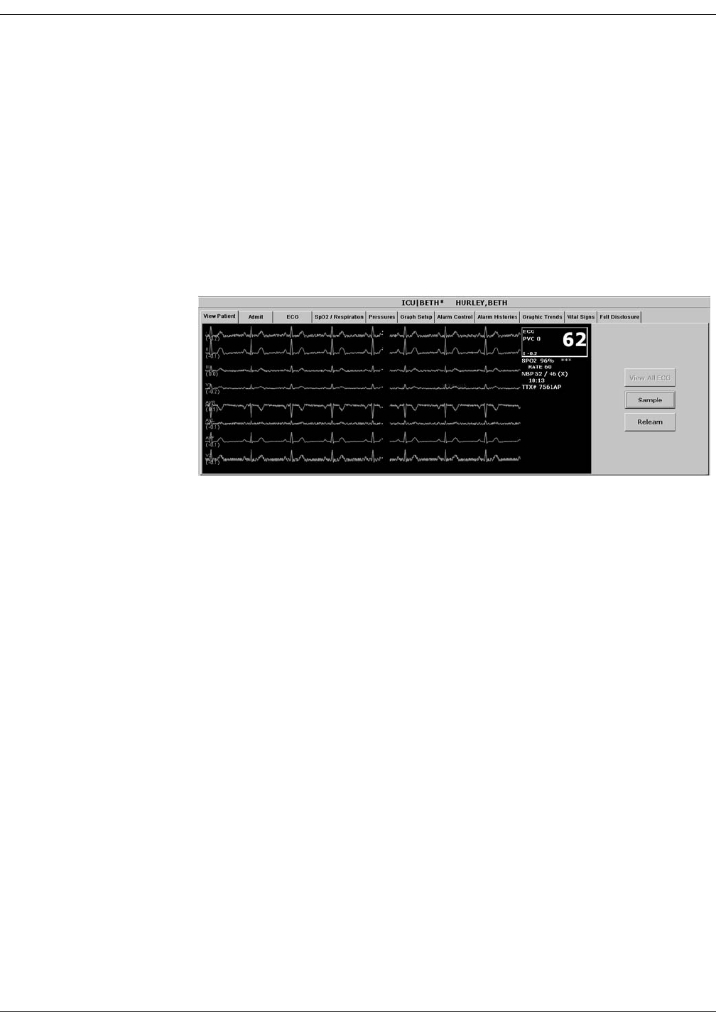
Revision D ApexPro Telemetry System 12-9
2001989-134
SpO2 Monitoring: SPO2 Monitoring
SPO2 in the Single Patient Viewer
In the single patient viewer, SpO2 data appears in the View Patient tab
sheet in the same format and location as it does in the multiple patient
viewer.
To access the View Patient tab sheet, follow the steps below.
1. Click in the desired patient’s bed window in the multiple patient
viewer. The display rearranges to accommodate the single patient
viewer for that patient.
2. If it is not already visible at the front of the tabs, click on the View
Patient tab to bring the tab sheet to the front.
For more information about the View Patient tab sheet, refer to Chapter
7, Admit/View a Patient, in this manual.
SPO2 Limits
You can adjust alarm limits for SPO2 and rate in the Alarm Control tab
sheet for each patient. SPO2 alarm limits cannot be set as unit defaults.
For more information on how to set the alarm limits, refer to Chapter 8,
Alarm Control, in this manual.
348D
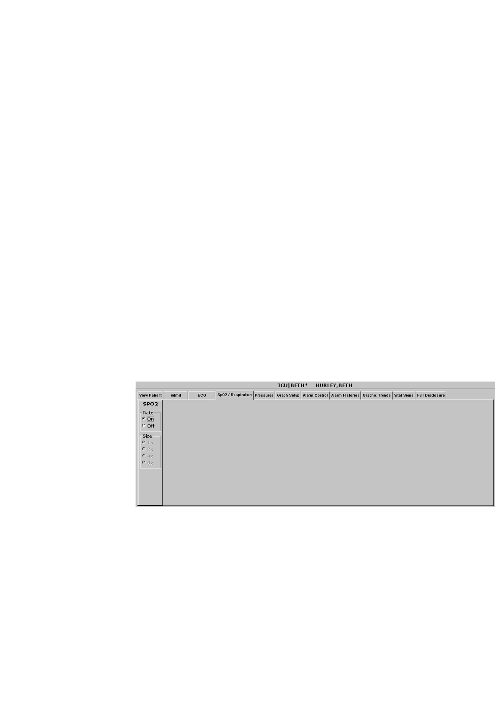
12-10 ApexPro Telemetry System Revision D
2001989-134
SpO2 Monitoring: SPO2 Tab Sheet
SPO2 Tab Sheet
The SpO2/Respiration tab sheet allows you to view and modify settings
specific to the viewed patient’s SpO2 display. Settings may be viewed for
any patient. However, you can only modify settings for patients who are
admitted to a bed in your unit.
NOTE
The SPO2 tab is labeled SpO2/Respiration because respiration
monitoring settings are available on this tab sheet for bedside
monitored patients only.
Respiration monitoring is not an option for telemetry patients.
Therefore only SpO2 information appears on this tab sheet when
monitoring a telemetry patient.
Accessing the SPO2 Tab Sheet
To access a patient’s SpO2 tab sheet in the single patient viewer, follow
this procedure.
1. Click in the desired patient’s bed window in the multiple patient
viewer. The display rearranges to accommodate the single patient
viewer for that patient.
2. Click on the SpO2/Respiration tab in the single patient viewer. The
SpO2 tab sheet moves to the front.
347B

Revision D ApexPro Telemetry System 12-11
2001989-134
SpO2 Monitoring: SPO2 Tab Sheet
Rate
A pulse rate is derived from the SPO2 signal and is displayed in the
parameter window. You can turn this displayed rate off and on. Simply
click On to turn rate on, or Off to turn rate off.
Size
Because no waveform is displayed when SpO2 is monitored via
telemetry, the Size option does not function for telemetry patients. Size
and its selections appear dimmed when monitoring telemetry patients.

12-12 ApexPro Telemetry System Revision D
2001989-134
SpO2 Monitoring: Troubleshooting
Troubleshooting
SpO2 Messages
Below is a list of system status alarm messages that may be displayed in
the patient’s bed window during monitoring. SpO2 messages appear in
abbreviated form in graph headers. If you are unable to resume SpO2
monitoring, contact your sales/service representative.
NOTE
The Xpod Oximeter can display the same SpO2 system status
messages as the Apex Oximeter, except for the CHANGE BATTERY
message. The Xpod Oximeter uses the battery power supplied by the
ApexPro transmitter and therefore does not support this message.
CHANGE BATTERY
Message displayed with SPO2 data displayed—The batteries in the Apex
Oximeter are low. There is approximately 1 hour of reserve power left in
the batteries. Change the batteries. Refer to Chapter 4, Connection, for
information about changing batteries.
Message displayed, no SPO2 data displayed—The batteries in the Apex
Oximeter are depleted. Replace the batteries. Refer to Chapter 4,
Connection, for information about changing batteries. This is a system
advisory alarm. The alarm will sound, and a red alarm button will
appear on the CIC Pro display. If the batteries are not replaced within 20
minutes, all SPO2 parameter information will be removed from the
display. If the batteries are replaced within 20 minutes, SpO2
monitoring will resume.
SPO2 PROBE
The probe has been disconnected from the oximeter (no data is
displayed).
SIGNAL
SpO2 data continues to be displayed, but the quality of the signal is
questionable. Check the patient and the probe.

Revision D ApexPro Telemetry System 12-13
2001989-134
SpO2 Monitoring: Troubleshooting
NO DATA
The oximeter is still connected, but no valid data is being transmitted to
the receiver. Check that the patient is within antenna range. If the
problem persists, contact GE Medical Systems Information Technologies
Service.
SPO2 PROBE OFF
The probe is off the patient. Check the probe.
The saturation value is X
The oximeter is still connected, but no valid data is being received at the
receiver. The patient may be in an area of poor antenna reception, where
some, but not all data is being transmitted.
This message remains on the CIC Pro for three minutes. If no data is
detected after three minutes, the message changes to NO DATA.

12-14 ApexPro Telemetry System Revision D
2001989-134
SpO2 Monitoring: Troubleshooting
For your notes

Revision D ApexPro Telemetry System 13-1
2001989-134
13 NBP Monitoring

13-2 ApexPro Telemetry System Revision D
2001989-134
For your notes

Revision D ApexPro Telemetry System 13-3
2001989-134
NBP Monitoring: Introduction
Introduction
NOTE
The Accutracker DX noninvasive blood pressure monitor is available
in the United States only. This model, available from GE Medical
Systems Information Technologies, has been modified by SunTech
Medical Instruments to operate with the ApexPro telemetry system.
NBP monitoring via telemetry is done with an Accutracker DX
noninvasive blood pressure monitor connected to the ApexPro
transmitter. The blood pressure cuff is connected to the Accutracker DX
blood pressure monitor, which measures and displays systolic and
diastolic blood pressures using the auscultatory method. When the blood
pressure monitor is connected to an ApexPro transmitter, digital values
are also displayed at the CIC Pro.
WARNING
The following conditions may affect the accuracy of
noninvasive blood pressure readings: seizures, tremors,
extreme hypotension or hypertension, arrhythmias, or
extremely high or low heart rate.

13-4 ApexPro Telemetry System Revision D
2001989-134
NBP Monitoring: Safety Considerations
Safety Considerations
Keep the following warnings and cautions in mind when using the
Accutracker DX noninvasive blood pressure monitor.
WARNINGS
The Accutracker DX noninvasive blood pressure monitor
is designed for use with adult patients only. Do not use
on neonates or on patients known to be susceptible to
bruising.
Do NOT attach the blood pressure cuff to a limb being
used for IV infusions as the cuff inflation can block the
infusion, causing harm to the patient.
CAUTIONS
The blood pressure monitor’s safety and effectiveness in
neonates has not been established.
Blood pressure measurements may be affected by the
patient’s position, physical condition, and other factors.
Do not use the blood pressure monitor if it has failed its
diagnostic self test or if it displays a pressure greater
than zero with no cuff attached. The values displayed by
such a unit may be inaccurate.
If you must ship the Accutracker DX noninvasive blood
pressure monitor for service or other reasons, place it in a
sealable plastic bag, seal it tightly, then package it in a
cardboard box. Label the shipping container “–20 to +50
Deg. C” and ship appropriately. Failure to follow these
instructions can result in device failure due to improper
shipping/storage conditions.

Revision D ApexPro Telemetry System 13-5
2001989-134
NBP Monitoring: Programming the Blood Pressure Monitor
Programming the Blood Pressure Monitor
The blood pressure measurement interval, the maximum and minimum
inflation pressures, dynamic or fixed inflate, and the deflate rate can all
be adjusted on the Accutracker DX blood pressure monitor. Follow the
instructions below to set these options.
Setting the Measurement Interval
When the blood pressure monitor is turned on, it performs a battery
voltage check, then the display shows the following:
INT= 5 (***)
INCR DECR START?
NOTE
The number 5 above represents any measurement interval, including
MAN (manual). When the blood pressure monitor is turned on, the
number displayed is the last measurement interval set as the
default.
Use the YES + button or the NO – button on the blood pressure monitor
to increase or decrease the interval (INT) at which the blood pressure
readings are taken.
The available measurement intervals are: MAN (manual), or 5, 6, 7, 8, 9,
10, 15, 20, 25, 30, 35, 40, 45, 50, 55, 60, 90, 120, or 240 minute intervals.
When the desired measurement interval is reached, press the START/
STOP button. The blood pressure monitor immediately begins a
measurement cycle. It will attempt one retry if the first measurement
cycle fails.
Measurements are taken at the selected interval. A measurement may
be initiated in between intervals by pressing the START/STOP button.
This “wakes up” the blood pressure monitor from sleep mode, and offers
the option to change the measurement interval as described above, as
well as the option to view the time left until the next measurement. A
manual measurement is initiated by pressing the START/STOP button
a second time. The next measurement will then be taken at the
scheduled interval (X number of minutes) after the manual
measurement is complete.

13-6 ApexPro Telemetry System Revision D
2001989-134
NBP Monitoring: Programming the Blood Pressure Monitor
The patient’s blood pressure is displayed for one minute on the blood
pressure monitor and for two hours on the CIC Pro. The blood pressure
reading is updated each time a measurement is successfully completed.
Measurements are taken at the selected interval until the blood pressure
monitor is turned off, or until the monitor determines that the batteries
are too weak for additional measurements.
A measurement may be stopped by pressing the START/STOP button
while the measurement is in progress.
Setting Test Parameters
The maximum and minimum inflation pressures, dynamic or fixed
inflate, and deflate rate can be adjusted. Follow these steps:
1. Turn the blood pressure monitor on while holding down the NO –
button. The display shows:
CHANGE TEST
PARAMETERS?
2. Press the YES + button to change the parameters.
3. The MAXIMUM PRESSURE can be set to: 250, 240, 230, 220, 210,
200, 190, 180, 170, 160, 150, 140, 130, 120, 110, or 100 mmHg using
the YES + and NO – buttons. A setting of 200 to 250 mmHg is
recommended for the maximum cuff inflation pressure.
4. When the maximum pressure has been set, press the NEXT button to
set the MINIMUM PRESSURE. It can be set to: 100, 90, 80, 70, 60,
50, 40, 30, 20, or 10 mmHg using the YES + and NO – buttons. A
setting of 40 mmHg is recommended for the minimum cuff deflate
pressure.

Revision D ApexPro Telemetry System 13-7
2001989-134
NBP Monitoring: Programming the Blood Pressure Monitor
5. When the minimum pressure has been set, press the NEXT button to
select DYNAMIC INFLATE or FIXED INFLATE. Press the YES +
button to turn dynamic inflate on, or press the NO – button for fixed
inflate.
When dynamic inflate is turned on, the blood pressure cuff inflation
pressure automatically ranges 30 mmHg above the most recent
systolic reading.
Fixed inflate always inflates the blood pressure cuff to the set
maximum inflation pressure.
Dynamic inflate is recommended for most patients. However, if a
patient’s systolic pressure readings vary by 25 mmHg or more, fixed
inflate may be more comfortable for the patient. In all likelihood,
dynamic inflate would not inflate the cuff high enough for such a
patient, prompting the blood pressure monitor to retry, and causing
the patient to endure two inflations for each reading. A fixed
inflation to the set maximum pressure eliminates the double
inflation and increases the patient’s comfort. Reducing the maximum
cuff inflation pressure setting for a patient being monitored with
fixed inflate will also increase the patient’s comfort.
6. After selecting dynamic or fixed inflate, the DEFLATE RATE can be
set. It can be set to: 6, 5, 4, 3, or 2 mmHg, using the YES + and NO –
buttons. A deflate rate of 3 mmHg per second is recommended.
NOTE
A patient with a slow heart rate requires a slower deflation rate
than a patient with a faster heart rate. If the cuff deflates too
quickly, it may not be possible to determine a blood pressure. If
the cuff deflates too slowly, it may be uncomfortable for the
patient. The recommended deflate rate of 3 mmHg per second
meets most patients’ requirements, but it can be adjusted when
needed.
7. Press the NEXT button to return to the CHANGE TEST
PARAMETERS? prompt, then press the NO – button to return to:
INT= 5 (***)
INCR DECR START?

13-8 ApexPro Telemetry System Revision D
2001989-134
NBP Monitoring: Programming the Blood Pressure Monitor
Setting Limits
It is possible to set the maximum and minimum values, as well as the
change (delta) limit, at which the blood pressure monitor will reject a
systolic, diastolic, or pulse pressure reading and attempt a new
measurement. Contact technical support (refer to “How to Reach Us” at
the beginning of this manual) for more information about setting these
limits.
Software and Hardware Versions
To verify what software and hardware versions your Accutracker DX
blood pressure monitor has, turn on the blood pressure monitor while
holding down the LAST button. A display similar to the following
appears:
Vsn: XX/ZZ
K3: 0 PR: 0
Your hardware version appears in place of the XX in the above example;
your software version appears in place of the ZZ in the above example.
NOTE
Although it is not shown on the Accutracker DX display, both the
software and hardware version have a period in them. For example,
if the hardware version reads 11 on the display, this actually
indicates that it is hardware version 1.1.

Revision D ApexPro Telemetry System 13-9
2001989-134
NBP Monitoring: Patient Preparation
Patient Preparation
Blood pressure cuff selection and application are important.
Inappropriate selection or improper application of the cuff will result in
erroneous measurements.
Most people use their non-dominant arm for acquiring ambulatory
noninvasive blood pressure readings.
Follow these steps to prepare the patient for NBP monitoring:
1. Place the K-sound microphone in the microphone pad (or blood
pressure cuff). For more information on microphone placement, refer
to the Microphone Placement section in this chapter.
2. Locate the patient’s brachial artery on the inside of the arm, just
above the elbow. Mark the location with a pen for easy microphone
placement.
3. Remove the backing from the microphone pad and adhere it in the
location marked on the patient’s arm. Do not bend or squeeze the
microphone. Route the microphone cable up, toward the patient’s
shoulder.
4. Wrap the blood pressure cuff around the arm. Be sure that the artery
marker is aligned over the brachial artery.
5. Drape the cuff hose over the patient’s shoulder and attach an
adhesive cuff anchor to the snap on the cuff hose. Do not adhere the
cuff anchor to the patient at this time.
6. Place the blood pressure monitor in its pouch and attach it to the
patient using the belt or shoulder strap provided.
7. Adhere the cuff anchor to the patient’s upper arm by removing the
adhesive backing and pressing firmly.

13-10 ApexPro Telemetry System Revision D
2001989-134
NBP Monitoring: Patient Preparation
When attached, the blood pressure cuff and hoses should be positioned
like those in the following illustration.
Patient with Cuff and Hoses Attached
Hoses Routed Over
Shoulder
Cuff Anchor Clip
Cuff/Microphone
Connections
408A

Revision D ApexPro Telemetry System 13-11
2001989-134
NBP Monitoring: Patient Preparation
Microphone Placement
A microphone is used to “hear” the Korotkoff sounds (K-sounds) that the
blood pressure monitor uses to determine the systolic and diastolic
pressure readings. The microphone can be placed in a microphone pad
and adhered to the patient’s arm under the blood pressure cuff, or
alternatively, it can be placed directly into the microphone pocket inside
the blood pressure cuff.
Placement in the Microphone Pad
Using a microphone pad is recommended. Place the microphone in the
pad as illustrated below. Do not bend or squeeze the microphone when
placing it in the pad, or when adhering the pad to the patient’s arm.
Placing the Microphone in the Microphone Pad
Microphone Cable
K-sound Microphone
Microphone Pad
410A

13-12 ApexPro Telemetry System Revision D
2001989-134
NBP Monitoring: Patient Preparation
Placement in the Blood Pressure Cuff
As already stated, using the microphone pad is recommended, especially
in the case of ambulatory patients or patients with weak K-sounds.
However, as an alternative, the microphone can also be placed directly in
the blood pressure cuff. Follow the directions below.
NOTE
Blood pressure readings taken with the microphone in the blood
pressure cuff may not be as accurate as readings obtained when
using the microphone pad.
1. Remove the bladder from the cuff.
2. Turn the cuff bladder pouch inside out to expose the microphone
pocket.
3. Open the Velcro pocket flap and gently insert the microphone into
the pocket.
4. When the microphone is completely inserted, close the Velcro flap
over the microphone cable and turn the cuff right side out.
5. Replace the bladder and exit the bladder hose and microphone cable
out of the same exit site, either right arm or left arm, as marked on
the cuff.
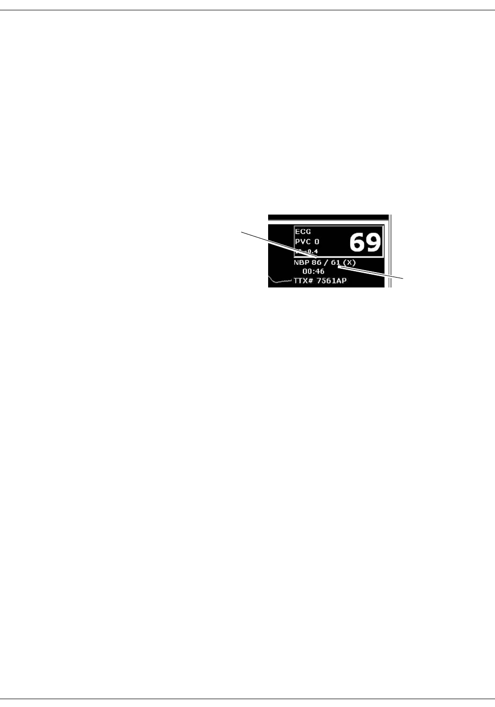
Revision D ApexPro Telemetry System 13-13
2001989-134
NBP Monitoring: NBP Monitoring
NBP Monitoring
NBP in the Multiple Patient Viewer
In the multiple patient viewer, the bed window for a telemetry patient
being monitored for NBP displays an NBP label, along with the systolic
and diastolic values from the most recent measurement.
NOTE
The mean blood pressure value is not measured or calculated when
monitoring blood pressure via telemetry. Therefore, an X always
remains on the display in place of a mean value when a telemetry
patient’s blood pressure is being monitored.
NBP in the Single Patient Viewer
In the single patient viewer, NBP data appears in the View Patient tab
sheet in the same format and location as it does in multiple patient
viewer.
To access the View Patient tab sheet, follow the steps below.
1. Click in the desired patient’s bed window in the multiple patient
viewer. The display rearranges to accommodate the single patient
viewer for that patient.
2. If it is not already visible at the front of the tabs, click on the View
Patient tab to bring the tab sheet to the front.
For more information about the View Patient tab sheet, refer to
Chapter 7, Admit/View a Patient, in this manual.
Systolic Value
Diastolic Value
401C

13-14 ApexPro Telemetry System Revision D
2001989-134
NBP Monitoring: NBP Monitoring
NBP Limits
You can adjust alarm limits for NBP in the Alarm Control tab sheet for
each patient. For more information on how to set the alarm limits, refer
to Chapter 8, Alarm Control, in this manual.
NOTE
The mean pressure limits can be changed, but there will be no effect
on alarms for telemetry patients because the mean pressure is not
measured or calculated for telemetry patients.
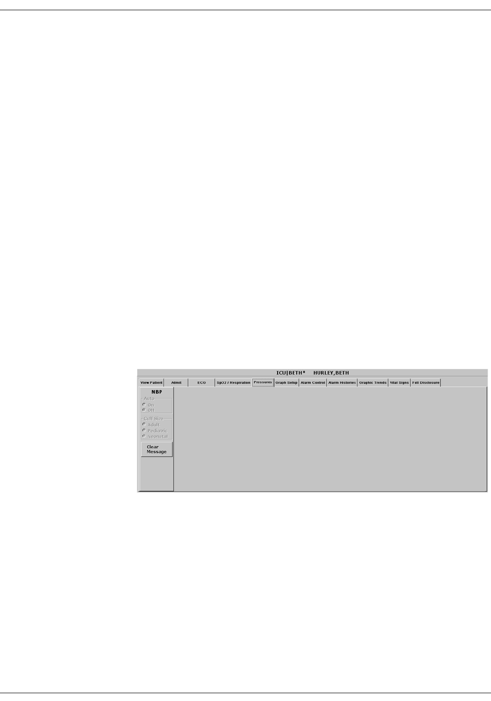
Revision D ApexPro Telemetry System 13-15
2001989-134
NBP Monitoring: Pressures Tab Sheet
Pressures Tab Sheet
The Pressures tab sheet allows you to view and modify settings specific
to the viewed telemetry patient’s NBP display. Settings may be viewed
for any patient. However, you can only modify settings for patients who
are admitted to a bed in your unit.
NOTE
The NBP tab is labeled Pressures because other invasive pressures
settings are available on this tab sheet for bedside monitored
patients only.
Invasive pressure monitoring is not an option for telemetry patients.
Therefore, only NBP information appears on this tab sheet when
monitoring a telemetry patient.
Accessing the Pressures Tab Sheet
To access a patient’s Pressures tab sheet in the single patient viewer,
follow this procedure.
1. Click in the desired patient’s bed window in the multiple patient
viewer. The display rearranges to accommodate the single patient
viewer for that patient.
2. Click on the Pressures tab in the single patient viewer. The Pressures
tab sheet moves to the front.
402B

13-16 ApexPro Telemetry System Revision D
2001989-134
NBP Monitoring: Pressures Tab Sheet
Auto
The interval for automatic NBP measurements is controlled at the blood
pressure monitor, not at the CIC Pro. Because the control is in the blood
pressure monitor, the Auto option is inactive for telemetry patients and
appears dimmed.
Cuff Size
The Cuff Size option is inactive for telemetry patients and appears
dimmed.
Clear Message
If you want to remove the displayed NBP values, use the mouse to click
on the Clear Message button. The values are replaced with Xs. In
addition, this action removes those values from vital signs history. Any
Message, Advisory, and Warning level NBP alarms are also cleared.

Revision D ApexPro Telemetry System 13-17
2001989-134
NBP Monitoring: Troubleshooting
Troubleshooting
Problem: Erroneous NBP
measurement
Solution:
1. Check for proper cuff size:
Too small a cuff can give an erroneously high value.
Too large a cuff can give an erroneously low value.
2. Check for residual air left in the cuff from a previous measurement.
This could indicate a hardware problem that may require service.
3. Make sure the cuff is not too tight or too loose.
4. Make sure the cuff and the heart are at the same level; otherwise
hydrostatic pressure will offset the NBP value.
5. Watch for pulsus paradoxis.
6. Check for leak in cuff or tubing.
7. Patient may have a weak pulse.
8. Calibration may be necessary.
NBP Status Messages
Below is a list of system status alarm messages that may be displayed in
the patient’s bed window during monitoring.
NBP status messages appear in abbreviated form in graph headers,
when applicable.
A message will clear when the next measurement is initiated, or a
message can be cleared manually with the Clear Message option on the
NBP tab sheet.
CHANGE BATTERY
An NBP measurement was attempted with low batteries. Change the
batteries in the blood pressure monitor and try another measurement.
FAIL
A hardware failure has been detected in the blood pressure monitor. In
the United States, contact GE Medical Systems Information
Technologies Service. Outside the United States, contact your local sales/
service representative.

13-18 ApexPro Telemetry System Revision D
2001989-134
NBP Monitoring: Troubleshooting
LEAK
The NBP cuff is loose or there is an air leak in the cuff or tubing. Check
that the cuff is on snugly. Check the connection between the cuff and the
tubing. Check the connection between the tubing and the blood pressure
monitor. Try another measurement. If the problem persists, contact your
local sales/service representative.
LOW INFLATION PRESS
This message appears when K-sounds are detected immediately upon
inflation. The inflation pressure is too low for proper NBP measurement.
Try another measurement or adjust dynamic/fixed inflate. Refer to the
Setting Test Parameters section in this chapter for more information. If
the problem persists, contact your local sales/service representative.
MOVEMENT
This message appears when there is excessive patient arm movement, or
if the patient’s arm was bent during the measurement. Check the patient
and try another measurement.
SENSOR?
This message appears when the K-sounds on the measurement were too
weak, or not enough sounds were detected. Reposition the microphone
and try another measurement. This message can also appear if the
deflate rate is not properly adjusted. Refer to Setting Test Parameters in
this chapter for more information. If the problem persists, contact your
local sales/service representative.
WEAK PULSE
The patient’s heart rate is erratic. Check that the microphone cable is
plugged firmly into the patient cable, and check that the microphone is
positioned correctly on the patient. Try another measurement. If the
problem persists, it could indicate a defective microphone, microphone
cable, or patient cable. Contact your local sales/service representative.

Revision D ApexPro Telemetry System A-1
2001989-134
AMessage Glossary

A-2 ApexPro Telemetry System Revision D
2001989-134
For your notes

Revision D ApexPro Telemetry System A-3
2001989-134
Message Glossary: Message Glossary
Message Glossary
Alarm Messages
The following messages appear in the patient’s bed window at the
Clinical Information Center.
ALARM PAUSE All alarms for this patient have been turned off
for five minutes. This is initiated from the
transmitter. Refer to ALL ALARMS OFF.
ALL ALARMS OFF All alarms for this patient have been turned off.
No graph strips run, arrhythmia events are not
stored, and no audible tones sound if an alarm
condition should occur.
NOTE
Refer to the Arrhythmia section in
Chapter 11, ECG Monitoring.
ARR OFF The arrhythmia program for a selected patient
has been turned off. No arrhythmia messages
are displayed, no graph strips run, and no
audible tones sound if an arrhythmia alarm
condition occurs.
ARTIFACT
ARR SUSPEND
All artifact begins at level 1. Sustained artifact
progresses to level 2 when noise on ECG lasts
for 20 of the last 30 seconds.
Level 1—Upon immediate detection of
artifact, the message ARTIFACT is
displayed. There is no alarm tone.
Level 2—Arrhythmia monitoring is
suspended in this condition. Heart rate and
PVC values change to X, an additional
message, ARR SUSPEND, is displayed.
LEADS FAIL All leads have failed. If set to Warning or
Advisory level, a system alarm is heard. This
will self-silence if condition is corrected, or the
user can silence for one minute with the Silence
Alarms button at the bottom of the CIC Pro
display.

A-4 ApexPro Telemetry System Revision D
2001989-134
Message Glossary: Message Glossary
NO TELEM The NO TELEM alarm occurs in two situations:
NOTE
Refer to the Suspended Analysis
warning in the Arrhythmia
section of Chapter 11, ECG
Monitoring.
1. The patient moves out of range.
Transmitter is out of range. A repeating,
low-pitched foghorn tone sounds after
sensing NO TELEM for 30 seconds. The
Silence Alarms button silences this alarm
for 60 seconds. If, after one minute, the NO
TELEM alarm condition is still present, the
alarm sounds again. Use the Alarm Off
Reason option when extended alarm
silencing is desired. Refer to Chapter 8,
Alarm Control, for more information about
this feature. Should a LEADS FAIL
condition occur prior to a NO TELEM
condition, the LEADS FAIL condition takes
priority. The LEADS FAIL message is
displayed along with the NO TELEM
message.
NOTE
Patient must be within antenna
range to receive a CHANGE
BATTERY message.
2. Transmitter batteries are extremely low or
dead.
If batteries are extremely low or completely
dead, the NO TELEM message appears, a
CHANGE BATTERY message appears in
the patient’s bed window, and the audible
alarm sounds. Activating the ALL ALARMS
OFF feature prevents the audible alarm
from sounding.

Revision D ApexPro Telemetry System A-5
2001989-134
Message Glossary: Message Glossary
Graph Messages
The following messages appear in the patient’s bed window on the
Clinical Information Center display. These relate to running graphs at
the printer.
OFF NETWORK In the Combo mode, telemetry patient data is
provided from the bedside monitor to the
Clinical Information Center. If the bedside
monitor is removed from the network or
becomes otherwise unavailable, the OFF
NETWORK alarm is generated. The Clinical
Information Center will then display patient
data directly from the telemetry bed along with
this message in that Clinical Information
Center bed window. Should the bedside monitor
reappear on the network, the Combo monitoring
application will automatically resume and the
alarm will be cleared.
This alarm is also generated if the receiver
system is removed from the network or becomes
otherwise unavailable. The bedside monitor
does not sound alarms, but the alarms must be
turned back on at the bedside monitor if they
were previously paused or off.
GRAPH ALARM An alarm graph was initiated and is running.
GRAPH MANUAL A manual graph was requested and is
running.
GRAPH TTX The Graph button on the transmitter was
pressed and a 20-second graph strip is
running.
PRINTING A non-real time graph is currently being
printed.
SAVING An alarm or a manual graph has been
requested but the writer is in use, the writer
door is open, or the writer is out of paper. The
request is saved and will run as soon as the
writer is available.

A-6 ApexPro Telemetry System Revision D
2001989-134
Message Glossary: Message Glossary
Transmitter-Related Messages
The following messages appear in the patient’s bed window on the
Clinical Information Center display.
System Status Messages
System status alarms (generated by mechanical conditions) are
displayed in the lower left corner of the Clinical Information Center
screen. Each message is preceded by the receiver system’s name, if it has
been entered, or a name created by using the last six numbers of the
receiver system Ethernet address. If necessary, call service (refer to
“How to Reach Us” at the front of the manual).
CHANGE BATTERY This message flashes when the batteries are
low. There is approximately 1 hour of use left
after this message appears. If the batteries
are extremely low or completely dead, a NO
TELEM message flashes, and an audible
alarm sounds.
LEADS FAIL All leads have failed. If set to Warning or
Advisory level, a system alarm is heard. This
will self-silence if condition is corrected, or
user can silence for one minute with Silence
Alarms button.
RA (LA, LL, V) FAIL One of these may appear, indicating failure of
a lead.
NO TELEM When the receiver can no longer reliably
receive patient signals from the programmed
transmitter, patient waveforms and heart
rate are removed from the display. If this
condition persists, call service.
DUPLICATE TOWER
NAME
A network problem exists. Restart the system.
Call service to correct this problem.
DUPLICATE NAME A network problem exists. Restart the system.
Call service to correct this problem.

Revision D ApexPro Telemetry System A-7
2001989-134
Message Glossary: Message Glossary
Patient Status Messages
Patient status messages are also displayed in the lower left corner of the
Clinical Information Center screen. They are not, however, preceded by
the receiver system name or Ethernet address.
“Unit/Bed” IS
UNMONITORED
A telemetry patient is admitted but is not
displayed (and therefore is unmonitored) on
any Clinical Information Center. If an alarm
occurs on an unmonitored bed, the
information will appear in the alarm text line
and an audible tone will sound. You must
view the patient first if you would like to
silence the alarm. To view an unmonitored
bed, click on the View Other button. (Refer to
Chapter 7, Admit/View a Patient for more
information on viewing a patient.)
“Unit/Bed”:
DUPLICATE NAME
There is another device on the network with
the same bed name. The duplicate device
must be renamed.

A-8 ApexPro Telemetry System Revision D
2001989-134
Message Glossary: Message Glossary
For your notes

Revision D ApexPro Telemetry System B-1
2001989-134
BSupplies

B-2 ApexPro Telemetry System Revision D
2001989-134
For your notes

Revision D ApexPro Telemetry System B-3
2001989-134
Supplies: Contact Information
Contact Information
To ensure patient safety, use only supplies manufactured or
recommended by GE Medical Systems Information Technologies. Your
local sales representative can provide current supplies lists, or you can
contact GE Medical Systems Information Technologies Supplies. (Refer
to “How to Reach Us” at the front of this manual.)

B-4 ApexPro Telemetry System Revision D
2001989-134
Supplies: Contact Information
For your notes

Revision D ApexPro Telemetry System C-1
2001989-134
CAbbreviations and
Symbols

C-2 ApexPro Telemetry System Revision D
2001989-134
For your notes

Revision D ApexPro Telemetry System C-3
2001989-134
Abbreviations and Symbols: Abbreviations and Symbols
Abbreviations and Symbols
Abbreviations and symbols which you may encounter while reading this
manual or using the Clinical Information Center are listed below with
their meanings.
Abbreviations
A
ABG arterial blood gas
AHA American Heart Association
APIC Association for Professionals in Infection Control and
Epidemiology, Inc.
AR arterial
ARRHY arrhythmia
ART arterial
AVF left foot augmented lead
AVL left arm augmented lead
AVR right arm augmented lead
B
BP blood pressure
Btu British thermal unit
C
CCelsius
Card Calc cardiac calculations
CCU critical care unit
CD coherent digital
CD-ROM compact disk-read only memory
CDT coherent digital telemetry

C-4 ApexPro Telemetry System Revision D
2001989-134
Abbreviations and Symbols: Abbreviations and Symbols
CE Conformité Européene
CH channelized
CIC clinical information center
CISPR International Special Committee on Radio Interference
cm centimeter
COMM communication
CPP cerebral perfusion pressure
CRT cathode ray tube
CSA Canadian Standards Association
CV central venous
CVP central venous pressure
D
DDW direct digital writer
DIA diastolic
E
ECG electrocardiograph
EEC European Economic Community
EN European Norm (European standard)
EMC electromagnetic compatibility
F
F Fahrenheit
FE, FEM femoral
G
GB gigabyte

Revision D ApexPro Telemetry System C-5
2001989-134
Abbreviations and Symbols: Abbreviations and Symbols
H
HRS hours
Hz hertz
I
IABP intra-aortic balloon pump
ICU intensive care unit
IEC International Electrotechnical Commission
in inch
ISO International Organization for Standardization
L
LA left arm
M
MAX maximum
MB megabyte
MCL modified chest lead
Mhz megahertz
mmHg millimeters of mercury
mm/S millimeters per second
MSDS Material Data Safety Specifications
N
NBP noninvasive blood pressure
O
OEM original equipment manufacturer
OR operating room

C-6 ApexPro Telemetry System Revision D
2001989-134
Abbreviations and Symbols: Abbreviations and Symbols
P
PA pulmonary artery
PC personal computer
PDS Patient Data Server
PPM parts per million
Pulm Calc pulmonary calculations
PVC premature ventricular contraction
Q
QRS interval of ventricular depolarization
R
RA right arm
RAM random access memory
RESP respiration
S
SP special
SpO2 arterial oxygen saturation
ST interval of ventricular repolarization
STD VGA standard graphics array
SYS systolic

Revision D ApexPro Telemetry System C-7
2001989-134
Abbreviations and Symbols: Abbreviations and Symbols
T
T1 temperature site 1
T2 temperature site 2
Temp, TMP temperature
TTX transmitter
U
UA umbilical artery
UAC umbilical artery catheter
UL Underwriters’ Laboratories
UV umbilical venous
V
V-Fib, V-FIB ventricular fibrillation
VAC voltage alternating current
VENT ventilator
Symbols
" inches
° degrees
±plus or minus
–minus
% percent

C-8 ApexPro Telemetry System Revision D
2001989-134
Abbreviations and Symbols: Abbreviations and Symbols
For your notes

Revision D ApexPro Telemetry System D-1
2001989-134
DApexPro FH Transceiver
(Not for sale outside of the United States)

D-2 ApexPro Telemetry System Revision D
2001989-134
For your notes

Revision D ApexPro Telemetry System D-3
2001989-134
ApexPro FH Transceiver: The Basics
The Basics
About the ApexPro FH Transceiver
The Wireless Medical Telemetry Services (WMTS) ambulatory
transceiver provides the link between the patient and the CIC Pro (or
other display) through the 608 - 614 MHz Medical Telemetry frequency
band. The ambulatory transceiver communicates data to the CIC Pro
through the Access Point transceiver. In addition, the ambulatory
transceiver is capable of receiving control commands for self-use or
connection transfer.
The ApexPro FH ambulatory transceiver is worn by the patient and
usually carried in a gown pocket or pouch. It is used with a 3, 5, or 6-wire
leadset that is connected to the electrodes on the patient. The ApexPro
FH transceiver is designed to be IPX7 compliant, so it can survive
inadvertent submersion.
The Access Point transceiver collects data from the ambulatory
transceiver, sends that data to the CIC Pro, and transmits control data to
the transceiver device.
WARNING
Remove transceivers from patients before MRI, CAT
scan, or X-Ray procedures, and store the transceivers
outside the room where such equipment is located. Close
proximity to MRI, CAT scan, or X-Ray equipment may
result in damage to transceivers.
D-4 ApexPro Telemetry System Revision D
2001989-134
ApexPro FH Transceiver: The Basics
Programming Transceivers
Before a transceiver can be used with the ApexPro FH Telemetry
System, it must first be programmed with a Network Key and TTX ID to
match the corresponding CIC Pro. Each ApexPro FH transceiver TTX ID
number must be entered at the corresponding CIC Pro. To enter the TTX
ID on the CIC Pro, refer to the CIC Pro Clinical Information Center
Operator’s Manual.
WARNING
When connected to a non-patient external device, such as a PC
for programming or Diagnostics, the ApexPro FH transceiver
must be removed from the patient. The I/O connector must be
covered, or used with an approved patient accessory, whenever
the ApexPro FH transceiver is connected to the patient.
Failure to keep the port covered when in use could lead to
excessive voltages and currents being applied to the
patient, resulting in cardiac arrest.
The transceiver TTX ID is located on the back label of the transceiver.
Transceiver TTX ID
Deactivate Mode
If two transceivers on the network have the same TTX ID, then the
second transceiver to be powered on will enter Deactivate Mode. In
Deactivate Mode, all LEDs on the front panel will illuminate and flash in
a rotating pattern and the device will not be operational. If the
transceiver enters this condition, contact your system administrator
immediately.

Revision D ApexPro Telemetry System D-5
2001989-134
ApexPro FH Transceiver: Safety
Safety
Warnings, Cautions, and Notes
Before operating the ApexPro FH transceiver, read and follow all
warnings and cautions presented in this section.
Warnings
WARNING
Do not use the output of the ApexPro FH transceiver as a
synchronization source for cardiac defibrillation. Delays
in presentation of the R-Wave exist.
Do not monitor pacer patients with a 3-wire leadset when
reliable pacer detection is required. Pacer pulse detection
can be erratic when only a single vector is monitored.
Always use a 5-wire or 6 leadset when reliable pacer
detection is required.
The ApexPro FH transceiver is a type CF patient applied
device. However it is not suitable for direct cardiac
application, for use in the operating room, or during
cardiac surgery. Use in these environments could cause
hazardous voltages and currents to be applied to the
patient’s heart, resulting in cardiac arrest.
Only allow approved accessories to be connected to the
I/O port of the ApexPro FH transceiver when connected
to a patient. Do not have the I/O port connected to a
computer for programming or for any other means, while
connected to a patient, as it could result in serious injury.
Only authorized devices can be plugged into the
accessory connector of the ApexPro FH transceiver when
it is applied to the patient. The accessory connector must
be kept covered when not in use with the supplied
accessory connector cover. Failure to follow these
instructions could lead to hazardous voltages and
currents being applied to the patient resulting in cardiac
arrest.
The ApexPro FH transceiver should not be intentionally
immersed. Total submersion of the patient worn
transceiver and/or patient leadset/antenna may severely
limit its transmission range causing loss of patient
monitoring. When subjecting the patient and transceiver
to submersion, he/she should be carefully monitored to
ensure that there is no signal loss.

D-6 ApexPro Telemetry System Revision D
2001989-134
ApexPro FH Transceiver: Safety
WARNINGS
Our transceivers have been validated to comply with the
requirements of IEC 60601-1-2. To prevent
electromagnetic interference, please ensure that any
other equipment used within the vicinity of the patient
meets the applicable requirements.
As with all medical telemetry systems, a single point
failure in the infrastructure could result in loss of
monitoring. Therefore, it is vital that the patient
displays be monitored by qualified personnel at all times.
Cautions
CAUTION
Any changes or modifications to the device that are not
expressly approved by the party responsible for
compliance could void the user’s authority to operate this
equipment.
Electromagnetic interference or power overload, due to
electrosurgical or diathermy instruments, may damage
the device. Do not use in the presence of electrosurgical,
diathermy, x-ray, or other generator instruments.

Revision D ApexPro Telemetry System D-7
2001989-134
ApexPro FH Transceiver: Safety
Notes
The ApexPro FH transceiver has been tested and found to comply
with the limits for a digital device, pursuant to Part 95H of the FCC
Rules. These limits are designed to provide reasonable protection
against harmful interference. This equipment generates, uses, and
radiates radio frequency energy, and, if not installed and used in
accordance with the instructions contained in this manual, may
cause harmful interference to other devices. However, there is no
guarantee that interference will not occur in a particular
installation.
If this equipment does cause harmful interference, then the user is
encouraged to try to correct the interference by one or more of the
following measures:
Move the ApexPro FH transceiver, or the device being interfered
with, to increase the separation between the two.
NOTE
Do not attempt to move fixed antennas as this can negatively
impact the ApexPro FH Telemetry System’s operation.
Connect the equipment into an outlet on a different circuit.
Contact your technical service representative for assistance.
To ensure that the use of this product does not contribute to
interference, it is necessary to use only approved cables. Use of non-
approved cables could result in harmful interference to radio or
television reception.
The components of the ApexPro FH Telemetry System (i.e. ApexPro
FH transceiver, Access Points, power cables, etc.) should be disposed
of per applicable regulations at the end of their useful life.

D-8 ApexPro Telemetry System Revision D
2001989-134
ApexPro FH Transceiver: Equipment Overview
Equipment Overview
ApexPro FH Transceiver Operating Instructions
The ApexPro FH transceiver is a battery-operated ambulatory
transceiver worn by the patient and used with a 3, 5, or 6-wire leadset
that is connected to electrodes on the patient.
Push Button Function and Use
See “ApexPro FH transceiver Controls and LED Indicators” on page D-11
for an image of the ApexPro FH transceiver controls and LED indicators.
External Serial Devices (I/O) Connector
The External Serial Device (I/O) connector allows an external serial
device or programming cable to connect and maintain a logical
communication link between the ApexPro FH transceiver, the CIC Pro,
and accessory devices. See “Programming Transceivers” on page D-4 for
details on programming the ApexPro FH transceiver through the I/O
connector.
ECG Leadset Connector
The ECG leadset connector allows the ECG leadset to attach to the
ApexPro FH transceiver and maintain a logical communication link
between the ApexPro FH transceiver and the CIC Pro. See “Attaching
and Removing a Leadset from the Transceiver” on page D-23 for details
on attaching the ECG leadset to the ApexPro FH transceiver through the
ECG leadset connector.
Remote Record
When depressed, the Remote Record function button will initiate a strip
chart recording at the CIC Pro.
Event Marker
When depressed, the Event Marker button marks a patient event. The
CIC Pro responds to an event marker by displaying a blue border around
the event bed and sounding an alarm tone. The message Remote Event
appears under the ECG parameter window for approximately ten
seconds.
The event marker will generate a 20-second graph and alarm history will
be stored. The graph feature can be turned off in the Setup CIC tab sheet,
Event Marker Graph On/Off.

Revision D ApexPro Telemetry System D-9
2001989-134
ApexPro FH Transceiver: Equipment Overview
Attendant Present/Procedure Alarm Silence (PAS) Unlock Button
The Attendant Present/PAS Unlock Buttons consists of two buttons
that are located on either side of the transceiver. (See “ApexPro FH
transceiver Controls and LED Indicators” on page D-11). The Attendant
Present push buttons have three functions. Each function is initiated
based on how long the buttons are pressed.
Lead Quality
Pressing both Attendant Present buttons simultaneously will illuminate
the LED for each lead that has a minimum level of quality.
Initiating an Attendant Present
Pressing the Attendant Present buttons will activate the Attendant
Present function and initiate an event log at the CIC Pro. The
Attendant Present event is not displayed on the CIC Pro. The event is
logged at the CIC Pro as Check Leads.
Unlocking the PAS button
The PAS button must be unlocked or enabled prior to initiating the
Procedure Alarm Silence button. In the “locked” position, the PAS button
is disabled.
To “unlock” the PAS button, press and hold (for about two seconds) the
Attendant Present buttons until the Procedure Alarm Silence Status
Indicator LED begins flashing. Once the LED indicator starts flashing,
the PAS button is in the “unlocked mode” and functional.
NOTE
The PAS button must be pressed while the LED is still flashing. If it
is pressed after the LED has stopped flashing, then the PAS button
will automatically be “re-locked”.

D-10 ApexPro Telemetry System Revision D
2001989-134
ApexPro FH Transceiver: Equipment Overview
Procedure Alarm Silence (PAS) Button
Depressing the PAS button, while the PAS Status Indicator LED is
flashing, informs the clinicians at the CIC Pro location that the
attending nurse will be performing a procedure to the patient that may
cause inadvertent false alarms at the CIC Pro (i.e. changing lead wires,
electrodes, etc.)
Once the PAS button is pressed, the following events occur at the CIC
Pro.
1. A timer is displayed in the fourth patient block configurable field
that displays the length of Procedure Alarm Silence time remaining
on the transceiver.
CAUTION
All non-level one alarms are ignored while the PAS alarm
is active.
2. “Alarm Pause” is denoted in Full Disclosure for the duration of the
PAS period.
Once the PAS button is pressed, the ApexPro FH transceiver enters the
PAS Mode with the following indications:
1. The active time is set for 120 seconds and begins counting down.
2. The active time is transmitted to the CIC Pro.
3. The PAS Status LED indicates the time remaining through its flash
speed. The LED flash speed increases as the PAS time remaining
decreases from 120 seconds to 0 seconds.
4. The attendant can reset the PAS active time to 120 seconds by
pressing both Attendant Present buttons again.
The Procedure Alarm Silence alarm remains active until one of the
following conditions occur:
1. The transceiver no longer sends the procedure alarm silence
indicator to the CIC Pro.
2. A level one alarm is detected and triggered at the CIC Pro.
3. The patient tile alarm text area is clicked on. All alarms are set to
ON once this area is clicked.
4. The attendant presses the PAS button while PAS is active. This will
automatically cancel the 120 second PAS at the CIC Pro, and will re-
enable the audible alarm tone.
NOTE
The PAS feature can be enabled/disabled by the System
Administrator.
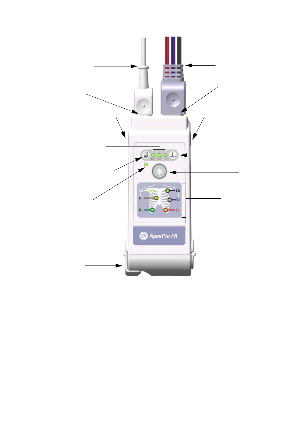
Revision D ApexPro Telemetry System D-11
2001989-134
ApexPro FH Transceiver: Equipment Overview
ApexPro FH transceiver Controls and LED Indicators
NOTE
*When connected to a non-patient external device, such as a PC for
programming or Diagnostics, the ApexPro FH transceiver must be removed from
the patient. The I/O connector must be covered, or used with an approved
patient accessory, whenever the ApexPro FH transceiver is connected to the
patient.
Battery Compartment
Electrode Status
Indicators
Remote Record
button
Battery Low, RF, and I/O
Connector Link Status Indicators
Procedure Alarm Silence button
Procedure Alarm Silence
Status Indicator
Event Marker button
Attendant Present / Procedure
Alarm Silence Unlock buttons
ECG Leadset and connector
cover
*External Serial Device (I/O)
Cable
ECG Leadset Connector
*External Serial Device (I/O)
Connector

D-12 ApexPro Telemetry System Revision D
2001989-134
ApexPro FH Transceiver: Equipment Overview
LED Indicators Function
Upon Power-On, all LED indicators are illuminated for a brief period.
After the specified time period, only those LEDs displaying positive (or
negative) transceiver functions, as described in each section below,
remain illuminated.
Procedure Alarm Silence Status Indicator
The Procedure Alarm Silence Status Indicator is illuminated when the
PAS function is active. The LED flashes while the Procedure Alarm
Silence button is unlocked or the PAS active time is running low. The
PAS button can only be pressed and activated during this unlocked
phase. Refer to the section on “Procedure Alarm Silence (PAS) Button” on
page D-10 for more information.
External Serial Devices (I/O)
The External Serial Device (I/O) LED is illuminated when an external
serial device is connected, detected and maintaining a logical
communication link.
WARNING
Only allow approved accessories to be connected to the
I/O port of the ApexPro FH transceiver when connected
to a patient. Do not have the I/O port connected to a
computer for programming, or for any other means, while
connected to a patient, as it could result in serious injury.
Low Battery (BATT)
The Low Battery (BATT) LED is illuminated while the battery voltage
remains good.The LED flashes will flash when the battery voltage is low.
When the battery power falls below a predetermined value, the
transceiver will automatically power itself off.
NOTE
If the ApexPro FH transceiver is powered on with a battery that
contains very low voltage, then all of the LEDs on the device will
flash on and off simultaneously. Replace the battery in the
transceiver to restore proper transceiver function.

Revision D ApexPro Telemetry System D-13
2001989-134
ApexPro FH Transceiver: Equipment Overview
RF link (RF)
The RF link indicator is illuminated while there is RF communication
between the ApexPro FH transceiver and the CIC Pro. The LED flashes
if there is communication between the ApexPro FH transceiver and the
Access point, but not the CIC Pro.
Electrode Status Indicators (RA, LA, RL, LL, Va, Vb)
Each ECG electrode wire is named, color coded (Table 2), and
represented by an LED indicator. Each LED is illuminated with a solid
light when the electrode is fully active, and is off when no electrode
signal is present.
Table 2. Electrode Colors
Electrode Name Wire Color
RA White
LA Black
RL Green
LL Red
V1 Brown
V2 Violet

D-14 ApexPro Telemetry System Revision D
2001989-134
ApexPro FH Transceiver: Connections
Connections
Connecting the ApexPro FH Transceiver to Accessory Devices
WARNING
Our transceivers have been validated to comply with the
requirements of IEC 60601-1-2. To prevent
electromagnetic interference, please ensure that any
other equipment used within the vicinity of the patient
meets the applicable requirements
The ApexPro FH transceiver can be connected to external, accessory
devices, and will transmit data from those devices to the Central Station.
The transceiver can connect to only the following accessory devices:
Apex Oximeter
Nonin XPod Assembly
Dinamap Pro
WARNINGS
Do not use accessory cables that exhibit signs of wear or
damage, such as cracking or degradation of the
connectors or cable insulation.
Make sure that the accessory cables are not
inadvertently pinched in the bed rails. This may cut the
cable insulation or break the connectors.
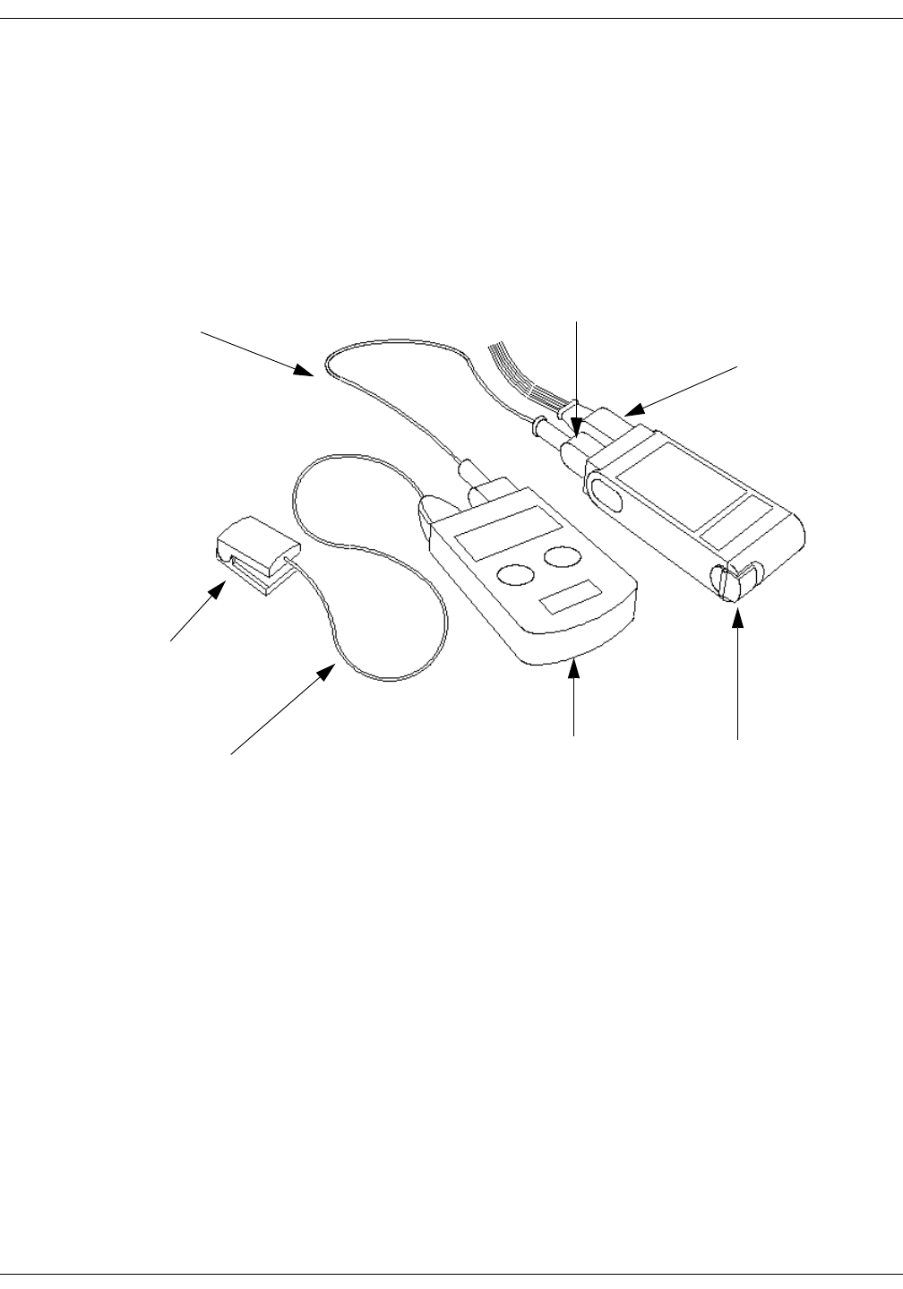
Revision D ApexPro Telemetry System D-15
2001989-134
ApexPro FH Transceiver: Connections
Apex Oximeter
To attach the ApexPro FH transceiver to the Apex Oximeter:
1. Plug the ApexPro FH Accessory Cable host connector into the
ApexPro FH transceiver I/O port, and the other end into the Apex
Oximeter I/O port.
2. Plug the Nonin SPO2 Sensor cable connector into the Apex Oximeter
accessory port.
Connecting to the Apex Oximeter Accessory Device
ApexPro FH
Transceiver
Apex Oximeter
Nonin SPO2
Sensor
ECG Leadset
Connector
I/O Port
Connector
ApexPro FH
Accessory Cable
Nonin SPO2
Sensor Cable
434A
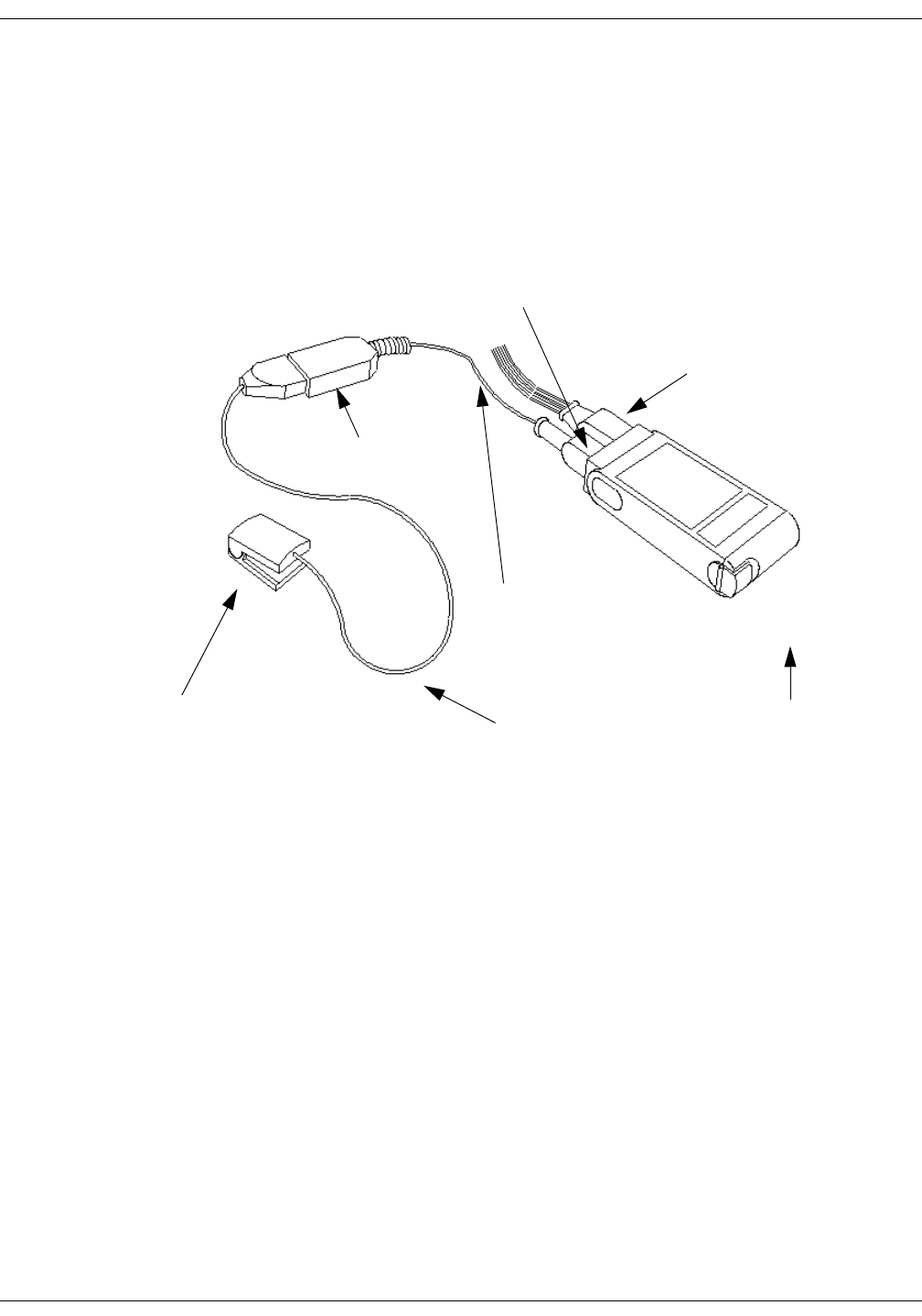
D-16 ApexPro Telemetry System Revision D
2001989-134
ApexPro FH Transceiver: Connections
Nonin XPod Assembly
To attach the ApexPro FH transceiver to the Nonin XPod Assembly:
1. Plug the Nonin XPod Accessory Cable host connector into the
ApexPro FH transceiver I/O port.
2. Plug the Nonin SPO2 Sensor cable connector into the Nonin XPod
assembly accessory port.
Connecting to the Nonin XPod Assembly Accessory Device
ApexPro FH
Transceiver
ECG Leadset
Connector
I/O Port
Connector
Nonin SPO2
Sensor Cable
Nonin SPO2
Sensor
Nonin XPod
Accessory Cable
Nonin XPod
Assembly
435A
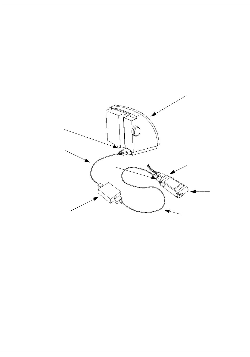
Revision D ApexPro Telemetry System D-17
2001989-134
ApexPro FH Transceiver: Connections
Dinamap Pro
To attach the ApexPro FH transceiver to the Dinamap Pro:
1. Plug the ApexPro FH Accessory Cable host connector into the
ApexPro FH transceiver I/O port, and the other end into the
DinaLink device.
2. Plug the DinaLink cable connector into the Data Interface Device
Connector on the back of the Dinamap Pro device, and the other end
into the DinaLink device.
ApexPro FH
Transceiver
Dinamap Pro
ECG Leadset
Connector
I/O Port Connector
ApexPro FH Accessory
Cable
Data Interface
Connector
DinaLink Cable
DinaLink
436A

D-18 ApexPro Telemetry System Revision D
2001989-134
ApexPro FH Transceiver: Maintenance
Maintenance
General Cleaning/Disinfecting
This section provides cleaning and maintenance instructions for ApexPro
FH transceivers.
Read and follow all precautions when cleaning transceivers.
WARNING
No claims are made concerning the sterility of the
ApexPro FH transceiver.
CAUTION
Do not sterilize any part of the transceivers. Gas
sterilization, autoclaving, liquid immersion, and other
sterilization methods can cause serious damage to the
devices that may not be obvious to the user.
NOTE
Do NOT use abrasive cleaners.

Revision D ApexPro Telemetry System D-19
2001989-134
ApexPro FH Transceiver: Maintenance
Cleaning the Chassis
CAUTION
Prior to cleaning the battery compartment and
transceiver chassis, remove the battery from the unit.
The following applies to cleaning the ApexPro FH transceiver.
The ApexPro FH transceiver can be cleaned with the patient cable
attached, however please ensure that the cleaning agents used to
clean the ApexPro FH transceiver are compatible with the cleaning
agents listed for the ECG cable on “Cleaning the ECG Leadsets” on
page D-21, or else ensure that the ECG cable does not come into
contact with the cleaning agents for the ApexPro FH transceiver.
To clean around the ECG connector, remove the ECG cable from the
unit.
1. Remove the battery from the transceiver and inspect the battery
compartment after each use. Close the battery door.
CAUTION
Prior to rinsing the ApexPro FH transceiver, make sure
that the battery compartment door is properly closed and
sealed.
2. Transceivers can be cleaned with a gauze pad or soft, lint-free cloth,
using the following solution, as recommended in the APIC Guideline
for Selection and Use of Disinfectants (1996):
Sodium hypochlorite (5.2% household bleach) 1:500 dilution (100
ppm free chlorine)
3. Use a cloth moistened with distilled water to rinse away the cleaning
solution.
4. Dry thoroughly with a lint-free cloth.
NOTE
Once a month, or whenever the ApexPro FH transceiver is
submersed or subjected to a stream of liquid, remove the accessory
connector cover and remove any moisture that may have collected
inside.

D-20 ApexPro Telemetry System Revision D
2001989-134
ApexPro FH Transceiver: Maintenance
Cleaning the Battery Compartment
CAUTIONS
The battery compartment is not waterproof.
Make certain fluids do not enter the electronics
through the air holes in the batter compartment
floor.
Cleaning the battery compartment in a manner other
than that specified below may cause the unit to
malfunction and void the warranty
Under normal operation, the battery compartment should not require
cleaning. If the battery compartment does require cleaning, then use the
following instructions.
1. Remove the battery from the battery compartment.
2. Clean the transceiver with a gauze pad or cloth lightly moistened
with one of the following agents:
Water
Soap
3. Use a cloth lightly moistened with distilled water to rinse away the
cleaning solution. Make certain that moisture does not enter the
electronics area below the battery compartment floor.
4. Dry thoroughly with a lint-free cloth. Allow the battery compartment
to air dry completely prior to closing the compartment door.

Revision D ApexPro Telemetry System D-21
2001989-134
ApexPro FH Transceiver: Maintenance
Cleaning the ECG Leadsets
The transceiver ECG Leadsets are manufactured by Affinity Medical.
Contact your technical support representative for additional leadsets.
WARNINGS
ECG lead wires must be dressed and secured to the
patient to prevent the possibility of them encircling
the patient’s neck and causing strangulation.
Do not use leadsets which exhibit signs of wear or
damage such as cracking or degradation of the
connectors or cable insulation.
Do not sterilize using steam or gamma radiation.
Damage to the leadsets will result.
CAUTIONS
To increase the life of the leadsets, do not pull on the
leadsets to disconnect. Pull gently by grasping the
connectors.
Do not immerse the leadsets in water or other liquid
to clean. Immersion may cause damage to the
leadsets.
Repeated exposure to EtO sterilization will shorten
the effective life of the leadset. The leadsets should be
sterilized only when indicated by specific patient or
hospital requirements.
Make sure that the wires are not twisted around each
other; since, this can interfere with transmission and
produce noise.
Make sure that the lead wires are not inadvertently
pinched in the bed rails. This may cut the insulation
or break the leadset.

D-22 ApexPro Telemetry System Revision D
2001989-134
ApexPro FH Transceiver: Maintenance
General Cleaning
1. Wipe the leadset with a solution of soap and water.
2. Use a cloth moistened with distilled water to rinse away the cleaning
solution.
3. Dry thoroughly with a lint-free cloth.
Disinfecting
Refer to the disinfecting instructions provided by the manufacturer.
Cleaning the Accessory Cables
General Cleaning
1. Wipe the accessory cable with a solution of soap and water.
2. Use a cloth moistened with distilled water to rinse away the cleaning
solution.
3. Dry thoroughly with a lint-free cloth.
Disinfecting
Refer to the disinfecting instructions provided by the manufacturer.

Revision D ApexPro Telemetry System D-23
2001989-134
ApexPro FH Transceiver: Maintenance
Storage and Usage
Transceiver Storage
Store the transceiver with the leadset attached and hanging freely. If
that is not possible, then wrap the leadset loosely around the transceiver.
Wrapping the leadset tightly around the transceiver can damage the
wires.
NOTE
The ApexPro FH transceiver contains no user-serviceable parts.
Thus, maintenance service is not needed.
Attaching and Removing a Leadset from the Transceiver
To attach, carefully grasp the leadset connector cover, holding it with the
small knob facing upward, and push the leadset into the ECG lead wire
connector. Make sure that the leadset is completely inserted into the
connector and is flush with the ApexPro FH transceiver chassis.
To remove the leadset, grasp hold of the sides of the leadset connector
cover and pull straight out. If the leadset is difficult to remove, then you
can slightly move the leadset cover side-to-side until it is released.
Internal Antenna
The ApexPro FH transceiver transmits in the 608-614 MHz frequency
range. The omnidirectional antenna is a part of the leadset system, with
each lead wire paired with an antenna wire. Transceiver output power
and system operation requirements are defined by the FCC. Therefore,
it is essential that the leadset provided not be modified or
altered in any way.

D-24 ApexPro Telemetry System Revision D
2001989-134
ApexPro FH Transceiver: Maintenance
Installing and Removing a Battery
NOTE
Battery service life can be substantially improved by using nine-volt
lithium batteries.
CAUTION
Do not attempt to insert the 9V battery into the battery
compartment in the opposite direction of that which is
specified. Incorrect battery insertion may result in
additional stress on the door hinge and battery contacts.
This may result in hinge breakage, poor battery contact,
and a decrease in transceiver performance.
To install a 9V battery, first open the transceiver battery compartment
by placing your thumb and forefinger on the compartment latch and
flipping it open. Inspect the battery compartment and insure that there
is no foreign object present that could block the battery contact or short
the battery terminals. Next, place a 9V battery inside the compartment
with the prongs touching the compartment contacts. The orientation of
the battery prongs against the contacts does not matter, so long as the
prongs and contacts are touching. Finally, close the battery compartment
door by pressing it until the latch clicks into place and the compartment
is secure.
To remove a battery, simply follow the installation steps listed above and
discard the used battery per applicable regulations.
NOTE
If a weak battery is inserted into a ApexPro FH transceiver, then all
of the LED indicators will continuously flash On and Off. Replace the
weak battery with a fully charged battery.
CAUTION
Prior to closing the battery compartment door, make sure
that the battery compartment latch is in the open
position. If the door is closed on the latch, then the
increased pressure could cause undue stress on the latch,
which may cause latch breakage.

Revision D ApexPro Telemetry System D-25
2001989-134
ApexPro FH Transceiver: Maintenance
WARNINGS
When installing or replacing the battery, visually
inspect the battery compartment and ensure that
there are no foreign objects inside. A conductive
object making contact with the battery contacts could
cause the battery and battery compartment to
overheat, resulting in burns to the patient and to the
attendant removing the battery.
A foreign object blocking battery contact with the
ApexPro FH transceiver could prevent its operation
resulting in failure to monitor the patient.
Always perform a battery check procedure after
installing or replacing the battery by pressing the
Attendant Present buttons.
Lithium Batteries may explode if mistreated. DO
NOT recharge, disassemble, or dispose of batteries in
fire.

D-26 ApexPro Telemetry System Revision D
2001989-134
ApexPro FH Transceiver: Compliance
Compliance
Compliance Statement
Table 3. Device UL and FCC Compliance
ApexPro FH Telemetry System equipment complying with part 15 of the
FCC rules: Operation is subject to the following conditions: (1) this device
may not cause harmful interference, and (2) this device must not accept
any interference received, including interference that may cause
undesired operation.
ApexPro FH Telemetry System equipment complying with Part 95H of
the FCC rules: Operation requires the prior coordination with a
frequency coordinator designated by the FCC for the Wireless Medical
Telemetry Service.
WARNING
Accessory equipment connected to the analog or digital
interface of the ApexPro FH Telemetry System must be
certified according to UL Electrical Safety Standards (UL
60950 for data processing equipment and UL 60601-1 for
medical equipment). You are responsible for making sure
that devices you connect to the ApexPro FH Telemetry
System comply with UL standards.
Device UL Compliance FCC Compliance Other
ApexPro FH Ambulatory
Transceiver
UL 60601-1 Part 95 Subpart H
(WMTS)
IPX7 Compliant
IEC 60601-1-2
DR-10000/ETAP UL 60950 Part 95 Subpart H
(WMTS) or Part 15
N/A

Revision D ApexPro Telemetry System D-27
2001989-134
ApexPro FH Transceiver: Compliance
UL Classification
The ApexPro FH transceiver is classified in accordance with UL 2601-1,
Type CF with Defibrillator Proof (5000V per AAMI EC-13-1992), and
IPX7 (according to IEC 60529-1989). The ApexPro FH transceiver has
been designed to withstand the effects of EMI and meets the EMC
requirements of IEC 60601-1-2 (April 1993). However, extremely high
levels of electromagnetic energy (above the levels of IEC 60601-1-2) may
still produce interference.
EMC Compliance and Requirements
The ApexPro FH transceiver is intended for use in the electromagnetic
environment specified in the table below. The customer or user of the
device should ensure that is used in such an environment.
Table 4. Electromagnetic Emissions for all equipment and systems.
ApexPro FH
WITH RESPECT TO ELECTRIC SHOCK, FIRE,
AND MECHANICAL HAZARDS ONLY
IN ACCORDANCE WITH UL2601-1/CAN/CSA
C22.2 NO. 601.1
4P41
Emissions Test Compliance Electromagnetic Environment Guidance
RF Emissions The device intensionally transmits energy in the 608-614
MHz range. Nearby electronic equipment may be
affected. Outside the range on intentional transmission,
the device emissions are very low and are not likely to
cause any interference.
Out of Band - CISPR 11 Group 1, Class B
In Band - 47 CFR 47 CFR 95 H
Harmonic Emissions
IEC 61000-3-2
Class A --
Voltage Fluctuations/Flicker
Emissions
IEC 61000-3-3
N/A The ApexPro FH Transceiver runs only on battery power.

D-28 ApexPro Telemetry System Revision D
2001989-134
ApexPro FH Transceiver: Compliance
The ApexPro FH transceiver is intended for use in the electromagnetic
environment specified in the table below. The customer or user of the
device should ensure that is used in such an environment
Table 5. Electromagnetic Immunity for all equipment and systems.
Immunity Test IEC 60601 Test Level Compliance Level Electromagnetic Environment Guidance
Electrostatic
Discharge (ESD)
IEC 61000-4-2
± 6 kV contact
± 8 kV air
± 6 kV contact
± 8 kV air
Floors should be wood, concrete, or ceramic
tile. If floors are covered with
synthetic material, then the relative humidity
should be at least 30%.
Electrical Fast Transient/Burst
IEC 61000-4-4
± 2 kV for power supply
lines
± 1 kV for input/output
lines
N/A The ApexPro FH transceiver runs only on
battery power.
Surge
IEC 61000-4-5
± 1 kV differential mode
± 2 kV common mode
N/A The ApexPro FH transceiver runs only on
battery power.
Voltage Dips, Short
Interruptions, and Voltage
Variations on Power Supply
Input Lines
IEC 61000-4-11
<5% UTa
(>95% dip in UT) for 0.5
cycle
N/A The ApexPro FH transceiver runs only on
battery power.
40% UT
(60% dip in UT) for 5
cycles
70% UT
(30% dip in UT) for 25
cycles
<5% UT
(>95% dip in UT) for 5
seconds
Power Frequency
(40/60 Hz) Magnetic Fields
IEC 61000-4-8
3 A/m 3 A/m Power frequency magnetic fields should be at
levels characteristic of a typical location in a
typical commercial or hospital
environment.
a. UT is the AC mains voltage prior to the application of the test level.
Revision D ApexPro Telemetry System D-29
2001989-134
ApexPro FH Transceiver: Compliance
The ApexPro FH transceiver is intended for use in the electromagnetic
environment specified in the table below. The customer or user of the
device should ensure that is used in such an environment.
Table 6. Electromagnetic Immunity for all non-life-supporting equipment and systems
NOTE
At 80 MHz and 800 MHz, the higher frequency range applies.
These guidelines may not apply in all situations. Electromagnetic propagation is affected by
absorption and reflection from structures, objects, and people.
Immunity Test IEC 60601
Test Level
Compliance
Level Electromagnetic Environment Guidance
Conducted RF
IEC 61000-4-6
3 Vrms
150 kHz to
80 MHz
0.5V = V1Portable and mobile RF communications equipment should be used no closer to any
part of the devices, including cables, than the recommended separation distance
calculated from the equation that is applicable to the frequency of the transmitter.
Recommended Separation Distance
Radiated RF
CFR 47
IEC 61000-4-3
3 V/m
80 MHz to
2.5 GHz
0.5V/m = V1
26 mHz to 1 GHz d =
d =
d =
where P is the maximum output power rating of the transmitter in watts (W) according
to the transmitter manufacturer and d is the recommended separation distance in
meters (m).
Field strengths from fixed RF transmitters, as determined by an electromagnetic site
surveya, should be less than the compliance level in each frequency rangeb.
Interference may occur in the vicinity of equipment marked with the following
symbol:
a. Field strengths from fixed transmitters, such as base stations for radio (cellular/cordless) telephones and land mobile
radios, amateur radio, AM and FM radio broadcast, and TV broadcast cannot be predicted theoretically with accuracy.
To assess the electromagnetic environment due to fixed RF transmitters, an electromagnetic site survey should be con-
sidered. If the measured field strength in the location in which the device is used exceeds the applicable RF compliance
level above, then the device should be observed to verify normal operation. If abnormal performance is observed, then
additional measures may be necessary, such as reorienting or relocating the device.
b. Over the frequency range 150 kHz to 80 MHz, field strengths should be less than 3 V/m for the DT-4500 and less
than 10 V/m for the DT-7000/DT-7001.
P
V
1
5.3
P
E
1
5.3
P
V
1
5.3
D-30 ApexPro Telemetry System Revision D
2001989-134
ApexPro FH Transceiver: Compliance
The ApexPro FH transceiver is intended for use in the electromagnetic
environment in which RF disturbances are controlled. The customer or
user of the device can help prevent electromagnetic interference by
maintaining a minimum distance between portable and mobile RF
communications equipment (transmitters) and the device, as
recommended below, according to the maximum power of the
communications equipment.
Table 7. Recommended Distances Between Portable and Mobile RF Communications
Equipment and the ApexPro FH transceiver
Rated Maximum Output Power
of Transmitter (W) Separation Distance According to Frequency of Transmitter (m)
150 to 80 MHz 80 Mz to 800 MHz 800 MHz to 2.5 GHz
d = d = d =
0.01 0.12 0.12 0.23
0.1 0.37 0.37 0.74
1 1.17 1.17 2.33
10 3.69 3.69 7.38
100 11.67 11.67 23.33
P
3
5.3 P
3
5.3 P
3
7

Revision D ApexPro Telemetry System D-31
2001989-134
ApexPro FH Transceiver: Compliance
FCC Compliance in the 608-614 MHz bands
1. The marketing and operation of intentional radiators, under the
provisions of the FCC rules, is restricted to biomedical telemetry
devices that are employed on health care facilities premises.
a. A health care facility includes hospitals and other
establishments that offer services, facilities, and beds for use
beyond 24 hours in rendering medical treatment, as well as
institutions and organizations that are regularly engaged in
providing medical services through clinics, public health
facilities, and similar establishments, including governmental
entities and agencies for their own medical activities.
b. This authority to operate does not extend to mobile vehicles, such
as ambulances, even if those vehicles are associated with a
health care facility.
2. The user and the installer of a biomedical telemetry device that is
operating within the frequency range 608-614 MHz, and that will be
located within 32 km of the very long baseline array (VLBA) stations
or within 80 km of any of the other radio astronomy observatories
noted in footnote US311 of 2.106 of this chapter, must coordinate
with, and obtain the written concurrence of, the director of the
affected radio astronomy observatory before the equipment can be
installed or operated. The National Science Foundation point of
contact for coordination is: Spectrum Manager, Division of
Astronomical Sciences, NSF Rm 1045, 4201 Wilson Blvd., Arlington,
VA 22230; tel: 703.306.1823.
3. Biomedical telemetry devices must not cause harmful interference to
licensed radio astronomy operation in the 608-614 MHz band. If
harmful interference occurs, then the interference must either be
corrected or the device must immediately cease operation on the
occupied frequency. Further, the operator of the biomedical
telemetry device must accept whatever level of interference is
received from other radio operations. The operator, i.e., the health
care facility, is responsible for resolving any interference that occurs
subsequent to the installation of these devices.

D-32 ApexPro Telemetry System Revision D
2001989-134
ApexPro FH Transceiver: Compliance
4. The manufacturers, installers, and users of biomedical telemetry
devices are reminded that they must ensure that biomedical
telemetry transceivers, which are operating under the provisions of
this section, avoid operating in close proximity to authorized services
using this spectrum. Sufficient separation distance, which is
necessary to avoid causing or receiving harmful interference, must be
maintained from co-channel operations.
PatientNet Component FCC Identifiers and Specifications
Model Number
Part Number
FCC ID
Max EPR (dBm)
Modulation
Receiver Predetection
Bandwidth (MHz)
Receiver Sensitivity (dBm)
Emission Designator
Lower Freq.
Upper Freq
Note
DR-10000 Z10020-001 BQI01DR-10000 16 GFSK 0.7 -87 300KFXD 608 614 Part 95H
ETAP Z10020-005 BQI02DR-10100 16 GFSK 0.7 -87 300KFXD 608 614 Part 95H
ApexPro FH APRO-FH-US-
ENG-AHA-4
BQI01DT-4500 3.5 GFSK 0.7 -87 230KFXD 608 614 Part 95H
Index

Index
Index-2 ApexPro Telemetry System Revision D
2001989-134
For your notes

Revision D ApexPro Telemetry System Index-3
2001989-134
Index
A
Abbreviations and symbols C-1
Accutracker DX noninvasive blood pressure monitor 3-
14, 13-3
Battery installation 4-10
Buttons and switches 3-15
Connections 4-12
Setup 13-5
Admit
HL7 admit data 7-6
Admitting 7-5–7-7
Alarm condition indicators 7-17
Alarm control 8-5–8-13
Alarm defaults 8-16
Alarm help 8-12
Alarm history
Deleting events 10-7
Print directory 10-6
Scanning events 10-6
Viewing events 10-6
Alarm off reason 8-10
Alarm pause breakthrough 8-14
Alarm volume 6-16
Apex Oximeter 4-7
Apex Oximeter connections 4-8
Battery installation 4-7
Buttons and LEDs 3-12
ApexPro CH transmitter 3-10
ApexPro FH transceiver 3-11, D-1
Basics D-3
Compliance D-26
Connections D-14
Equipment overview D-8
Maintenance D-18
Safety D-5
ApexPro telemetry system 3-4
ApexPro transmitter
Battery installation 4-3
Buttons and LEDs 3-7
Dust covers 3-9
Pausing alarms 3-8
Arrhythmia 11-24–11-29
Full arrhythmia conditions 11-26
Lethal arrhythmia conditions 11-29
Asystole 11-29
Brady 11-29
V Tach 11-29
VFib/VTach 11-29
Troubleshooting 11-33
Artifact 11-14
B
Battery installation
Accutracker DX noninvasive blood pressure
monitor 4-10
Apex Oximeter 4-7
ApexPro transmitter 4-3
Blood pressure monitor 3-14, 13-3
C
Cautions 2-8
CE marking information CE-1
Compliance CE-1, CE-7
Exceptions CE-2
Check box controls 1-8
CIC defaults 6-14
CIC setup 6-3
Classifications 2-13
Click 1-7
Controls
check boxes 1-8
radio buttons 1-7
scroll bars 1-8
Conventions
Buttons 1-5
Messages/Prompts 1-6
Multiple patient viewer 1-6
Single patient viewer 1-6
Tab options 1-6
Tab sheets 1-6
Tabs 1-6
Current telemetry listings 6-16
D
Dangers 2-4
Default settings 6-4
Unit defaults worksheet 1-10
Discharge instructions 7-8
E
ECG
Electrode placement 11-4
In the multiple patient viewer 11-11
In the single patient viewer 11-12
Patient preparation 11-4
Signal quality 11-9
Skin preparation 11-4
ECG tab sheet
Accessing 11-15
Detect pace 11-17–11-20
Einthoven + V lead electrode placement 11-5
Electrode placement 11-4
3-leadwire 11-6
5-leadwire 11-5
6-leadwire 11-5
Einthoven + V lead electrode 11-5
Modified chest lead (MCL) 11-7

Index
Index-4 ApexPro Telemetry System Revision D
2001989-134
Pacemaker patients 11-8
Pediatric patients 11-6
Equipment inspection 5-4
F
False asystole 11-33
False ventricular calls 11-34
FCC compliance CE-7, 2-15
RF exposure 2-14
Full arrhythmia 11-25
G
Graph all patients 9-6
Graph button
IMPACT.wf paging system 3-8, 9-4
Graph control menu 9-12
Graph location defaults 9-8
Graph on alarm 9-14
Graphic trends
Scanning 10-11
Select parameters for graphic trends 10-11
Time resolution 10-10
Trend directory 10-8
Graphing 9-3–9-10
Automatic alarm graphs 9-3
Graph all patients 9-6
Graph location defaults 9-8
Graph messages 9-5
Graph paper out 9-10
Manual graphs 9-4
Stopping a graph 9-9
Transmitter initiated graphs 9-4
H
HL7 admit data 7-6
I
IMPACT.wf paging system
View on demand 3-8, 9-4
Inaccurate pacemaker detection 11-36
L
Laser printer 9-16
Lead analysis 11-22
Multi-lead analysis 11-22
Single lead analysis 11-22
Leadwires
Multi-Link leadwire sets 4-6
Lethal arrhythmia 11-29
M
Manual graphs 9-4
Monitoring
6-lead 11-10
MUSE system
admit information from 7-6
N
NBP monitoring
In the multiple patient viewer 13-13
In the single patient viewer 13-13
Patient preparation 13-9
Microphone placement 13-11
P
Pacemaker pulse detection 11-19
False calls 11-17
Pace 1 11-19
Pace 2 11-19
Pace help 11-21
Rate meters 11-17
Pacemaker spike 11-17
Pacemaker troubleshooting 11-35
Patient preparation 11-4
Patient status alarms 8-3
Popup lists 1-9
Pressures tab sheet
Accessing 13-15
Clear message 13-16
Q
QS system
admit information from 7-6
R
Radio button control 1-7
Reference Literature 2-12
Relearn 7-13, 10-7, 11-16
S
Scroll bar controls 1-8
Service password 6-5
Six lead monitoring 11-10
SpO2 monitoring
In the multiple patient viewer 12-8
In the single patient viewer 12-9
Signal strength 12-6
SPO2 tab sheet
Accessing 12-10
Rate 12-11
Size 12-11
ST analysis 11-31
ST deviation alarm 11-32
ST measurement 11-31
ST troubleshooting 11-37
Supplies B-1
System status alarms 8-4
T
Technical maintenance 5-11
Telemetry transmitters
Apex transmitter battery installation 4-5
Setup 3-6
Storage 5-10

Revision D ApexPro Telemetry System Index-5
2001989-134
Index
Telemetry unit defaults
Changing 6-8
Viewing 6-7
Transmitter graph 9-14
Troubleshooting
NBP 13-17
Pacemaker 11-35
SpO2 messages 12-12
ST 11-37
U
Underwriters Laboratories, Inc 2-13
Unit defaults worksheet 1-10
User mode 6-3
V
Ventricular arrhythmia 11-24
View on demand 3-8, 9-4
Viewing a patient 7-12
Viewing another patient 7-14
In the multiple patient viewer 7-15
In the single patient viewer 7-14
Vital signs
Printing 10-15
W
Warnings 2-4

Index
Index-6 ApexPro Telemetry System Revision D
2001989-134
For your notes

World Headquarters
GE Medical Systems
Information Technologies, Inc.
8200 West Tower Avenue
Milwaukee, WI 53223 USA
Tel: + 1 414 355 5000
1 800 558 5120 (US only)
Fax: + 1 414 355 3790
European Representative
GE Medical Systems
Information Technologies GmbH
Munzinger Straße 3-5
D-79111 Freiburg
Germany
Tel: + 49 761 45 43 - 0
Fax: + 49 761 45 43 - 233
Asia Headquarters
GE Medical Systems
Information Technologies Asia; GE (China) Co., Ltd.
24th Floor, Shanghai MAXDO Center,
8 Xing Yi Road, Hong Qiao Development Zone
Shanghai 200336, P.R. China
Tel: + 86 21 5257 4650
Fax: + 86 21 5208 2008
0459
gemedical.com