GE AVM4160DF3BS User Manual MICROWAVE Manuals And Guides 1404512L
User Manual: GE AVM4160DF3BS AVM4160DF3BS GE MICROWAVE - Manuals and Guides View the owners manual for your GE MICROWAVE #AVM4160DF3BS. Home:Kitchen Appliance Parts:GE Parts:GE MICROWAVE Manual
Open the PDF directly: View PDF ![]() .
.
Page Count: 52
i
Installation
Instructions Over the Range
Microwave Oven
AVM4160,JNM3161,JVM3160,
and RVM5160
Questions? Carl 800. GE.CARES (800.432.2737) or Visitour Website at: GEAppliances.com i
BEFORE YOU BEGIN
Read these instructions completely and carefully.
• IMPORTANT - Savethese
instructions for local inspector's use,
• IMPORTANT - Observea,,
governing codes and ordinances,
• Note to Installer -Be sure to leave these
instructions with the consumer,
• Note to Consumer - Keep these instructions
for future reference,
• Skill level - Installation of this appliance requires basic
mechanical and electrical skills,
Proper installation is the responsibility of the installer,
Product failure due to improper installation is not
covered under the warranty,
Throughout this manual, features and appearance may
vary from .your model.
49-40675-2
(12-13 OE)
READ CAREFULLY.
KEEP THESE INSTRUCTIONS.
CONTENTS
General information
Installation
Important Safety Instructions ........................................ 3
Electrical Requirements .................................................. 3
Tools You Will Need ......................................................... 4
Hood Exhaust ................................................................. 5,6
Damage - Shipment/Installation .................................. 7
Parts Included ................................................................... 7
Mounting Space ................................................................ 8
Step-by-step installation guide
Placement of Mounting Plate ................................... 9-11
Removing the Mounting Plate ............................. 9
Finding the Wall Studs .......................................... 9
Determining Mounting Plate Location .............. 10
Aligning the Mounting Plate .............................. 11
Installation Types ..................................................... 12-23
_ Recirculating .................................................. 13-16
Attach Mounting Plate to Wall ................ 13
Preparation of Top Cabinet ...................... 13
Adjust the Blower ...................................... 14
Installing the Charcoal Filter .................... 15
Mount the Microwave Oven .............. 15, 16
Installing the Charcoal Filter
without Top Access ............................ 16
[_] Outside Top Exhaust ..................................... 17-20
Attach Mounting Plate to Wall ................. 17
Preparation of Top Cabinet ....................... 18
Adjust Blower Motor .................................. 18
Assemble and Install Adaptor .................. 19
Mount the Microwave Oven .............. 19, 20
Connecting Ductwork ................................ 20
Instructions
[C_ Outside Back Exhaust .................................. 21-24
Installation Overview ................................ 21
Preparing Rear Wall for
Outside Back Exhaust ................................ 21
Attach Mounting Plate to Wall .......... 21, 22
Preparation of Top Cabinet ....................... 22
Adapting Blower for Outside
Back Exhaust .......................................... 22, 23
Mount the Microwave Oven .............. 23, 24
Before You Use Your Microwave Oven ..................... 25
2
Installation Instructions
IMPORTANT SAFETY INSTRUCTIONS
A qualified electrician must perform a ground continuity
check on the wall receptacle before beginning the
installation to ensure that the outlet box is properly
grounded, If not properly grounded, or if the wall
receptacle does not meet electrical requirements noted
(under ELECTRICAL REQUIREMENTS), a qualified electrician
should be employed to correct any deficiencies.
AWARNING:
Risk of Electric Shock.
Can cause injury or death:
Remove house fuse or
open circuit breaker before
beginning installation to avoid
severe or fatal shock injury.
_VV/_K|_I| |_1_: Risk of Electric Shock.
Can cause injury or death: THIS APPLIANCE MUST BE
PROPERLY GROUNDED to avoid severe or fatal shock.
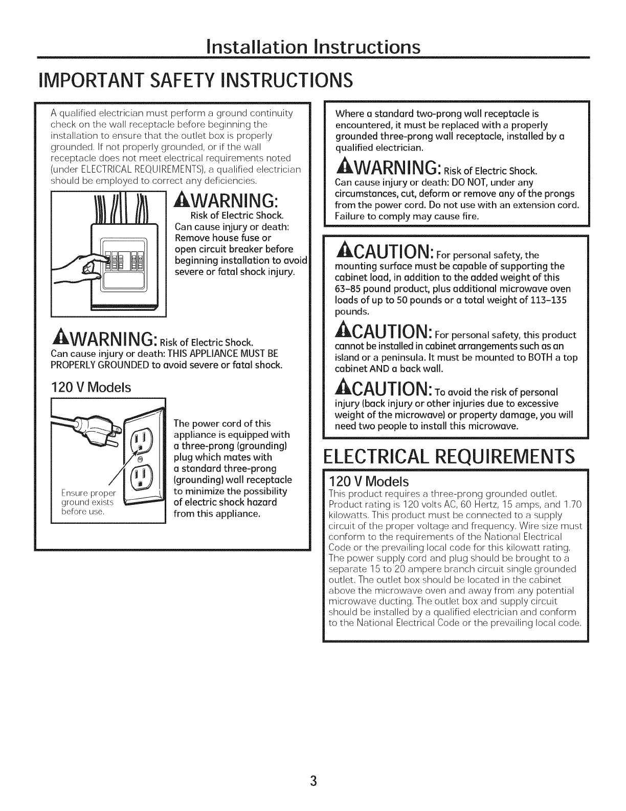
120 V Models
before use,
The power cord of this
appliance is equipped with
a three-prong (grounding}
plug which mates with
a standard three-prong
(grounding} wall receptacle
to minimize the possibility
of electric shock hazard
from this appliance.
Where a standard two-prong wall receptacle is
encountered, it must be replaced with a properly
grounded three-prong wall receptacle, installed by a
qualified electrician.
AWARN ING:RiskofElectricShock.
Can cause injury or death: DO NOT, under any
circumstances, cut, deform or remove any of the prongs
from the power cord, Do not use with an extension cord,
Failure to comply may cause fire,
Ar, Ai iTir i
_U||U|_: For personal safety, the
mounting surface must be capable of supporting the
cabinet load, in addition to the added weight of this
63-85 pound product, plus additional microwave oven
loads of up to 50 pounds or a total weight of 113-135
pounds.
ACAUTION: For personal safety, this product
cannot be installed in cabinet arrangements such as an
island or a peninsula. It must be mounted to BOTH a top
cabinet AND a back wall.
|_i'_U||U|\l: To avoid the risk of personal
injury (back injury or other injuries due to excessive
weight of the microwave) or property damage, you will
need two people to install this microwave.
ELECTRICAL REQUIREMENTS
120 V Models
This product requires a three-prong grounded outlet.
Product rating is 120 volts AC, 60 Hertz, 15 amps, and 1.70
kilowatts. This product must be connected to a supply
circuit of the proper voltage and frequency. Wire size must
conform to the requirements of the National Electrical
Code or the prevailing local code for this kilowatt rating.
The power supply cord and plug should be brought to a
separate 15 to 20 ampere branch circuit single grounded
outlet. The outlet box should be located in the cabinet
above the microwave oven and away from any potential
microwave ducting. The outlet box and supply circuit
should be installed by a qualified electrician and conform
to the National Electrical Code or the prevailing local code.
3
Installation Instructions
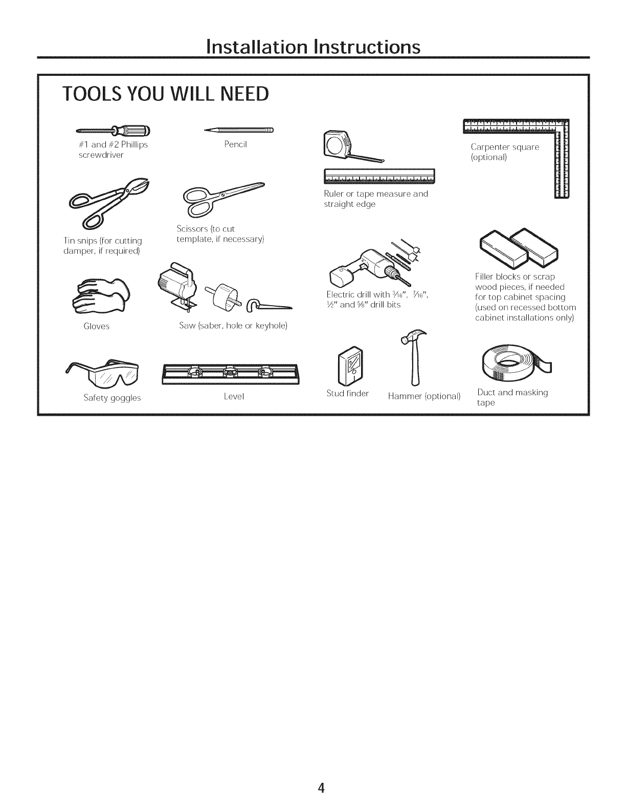
TOOLS YOU WILL NEED
#1 and #2 Phillips Pencil
screwdriver
Tin snips (for cutting
damper, if required)
Scissors (to cut
template, if necessary)
Gloves
Safety goggles
@:==_
Saw (saber, hole or keyhole)
Level
Lhh,,l.,.JJ._._l,d.J,.L.bJ,,._.,,_.h.l,._.,.L.hL,,J.,.]
Ruler or tape measure and
straight edge
Electric drill with %6", 7A6",
_" and %" drill bits
Carpenter square
(optional)
Filler blocks or scrap
wood pieces, if needed
for top cabinet spacing
(used on recessed bottom
cabinet installations only)
Stud finder Hammer (optional) Duct and masking
tape
4
Installation Instructions
HOOD EXHAUST
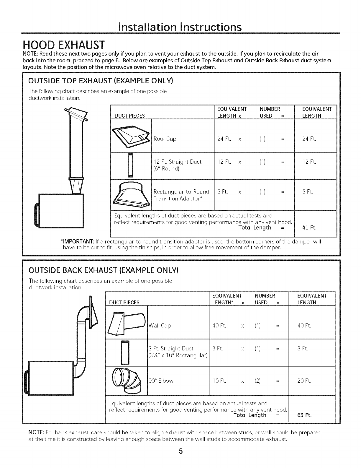
NOTE: Read these next two pages only if you plan to vent your exhaust to the outside. If you plan to recirculate the air
beck into the room, proceed to page 6. Below ore examples of Outside Top Exhaust end Outside Beck Exhaust duct system
layouts. Note the position of the microwave oven relative to the duct system.
OUTSIDE TOP EXHAUST {EXAMPLE ONLY}
The following chart describes an example of one possible
ductwork installation,
m
L_]
DUCT PIECES
II
[]
Roof Cap
12 Ft, Straight Duct
(6" Round)
Rectangular-to-Round
Transition Adaptor*
EQUIVALENT NUMBER EQUIVALENT
LENGTH x USED = LENGTH
24 Ft, x (1)
12 Ft, x (1)
5 Ft, x (1)
Equivalent lengths of duct pieces are based on actual tests and
reflect requirements for good venting performance with any vent hood,
Total Length =
24 Ft,
12 Ft,
5 Ft,
41 Ft.
*IMPORTANT: If a rectangular-to-round transition adaptor is used, the bottom corners of the damper will
have to be cut to fit, using the tin snips, in order to allow free movement of the damper,
OUTSIDE BACK EXHAUST {EXAMPLE ONLY}
The following chart describes an example of one possible
ductwork installation,
DUCT PIECES
Wall Cap
3 Ft, Straight Duct
3}4" x 10" Rectangular)
90 ° Elbow
EQUIVALENT NUMBER EQUIVALENT
LENGTH* x USED = LENGTH
40 Ft, x (1) =
S Ft, x (1) =
10 Ft, x (2) =
Equivalent lengths of duct pieces are based on actual tests and
reflect requirements for good venting performance with any vent hood,
Total Length =
40 Ft,
3 Ft,
20 Ft,
63 Ft.
NOTE: For back exhaust, care should be taken to align exhaust with space between studs, or wall should be prepared
at the time it is constructed by leaving enough space between the wall studs to accommodate exhaust,
5
Installation Instructions
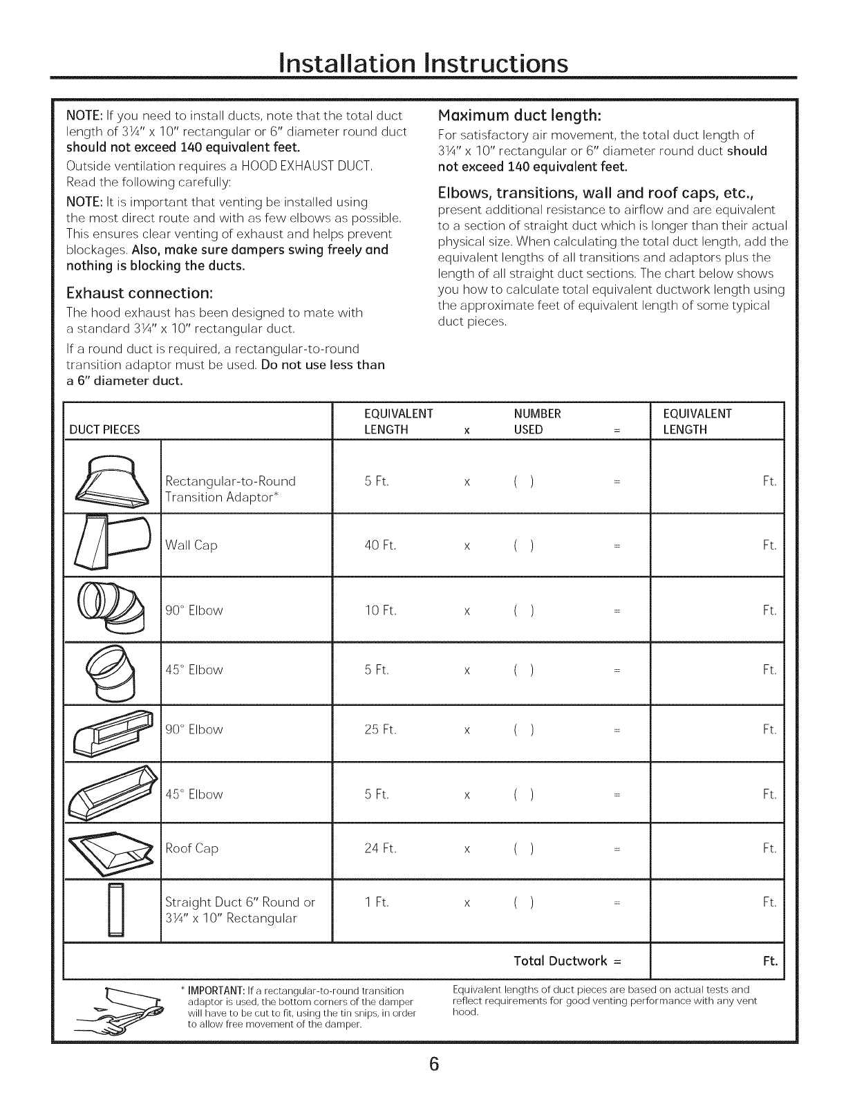
NOTE: If you need to install ducts, note that the total duct
length of 3_¼'' x 10" rectangular or 6" diameter round duct
should not exceed 140 equivalent feet.
Outside ventilation requires a HOOD EXHAUST DUCT,
Read the following carefully:
NOTE: It is important that venting be installed using
the most direct route and with as few elbows as possible,
This ensures clear venting of exhaust and helps prevent
blockages, Also, make sure dampers swing freely and
nothing is blocking the ducts.
Exhaust connection:
The hood exhaust has been designed to mate with
a standard 3X" x 10" rectangular duct,
If a round duct is required, a rectangular-to-round
transition adaptor must be used, Do not use less than
a 6" diameter duct.
Maximum duct length:
For satisfactory air movement, the total duct length of
3X'x 10" rectangular or 6" diameter round duct should
not exceed 140 equivalent feet.
Elbows, transitions, wall and roof caps, etc.,
present additional resistance to airflow and are equivalent
to a section of straight duct which is longer than their actual
physical size, When calculating the total duct length, add the
equivalent lengths of all transitions and adaptors plus the
length of all straight duct sections, The chart below shows
you how to calculate total equivalent ductwork length using
the approximate feet of equivalent length of some typical
duct pieces,
DUCT PIECES
Rectangular-to-Round
Transition Adaptor*
Wall Cap
90 ° Elbow
EQUIVALENT
LENGTH
5 Ft,
40 Ft,
10 Ft,
NUMBER
USED
()
()
( )
EQUIVALENT
LENGTH
Ft,
Ft,
Ft,
(_ 45 ° Elbow 5 Ft, x ( ) : Ft,
90 ° Elbow 25 Ft, x ( ) = Ft,
_ 45 °Elbow 5Ft, x ( ) = Ft,
Roof Cap 24 Ft, x ( ) = Ft,
Straight Duct 6" Round or 1 Ft, x ( ) = Ft,
3X" x 10" Rectangular
Total Ductwork = Ft.
* IMPORTANT: If a rectangular-to-round transition
adaptor is used, the bottom corners of the damper
will have to be cut to fit, using the tin snips, in order
to allow free movement of the damper.
Equivalent lengths of duct pieces are based on actual tests and
reflect requirements for good venting performance with any vent
hood.
6
Installation Instructions
DAMAGE- SHIPMENT/
INSTALLATION
• If the unit is damaged in shipment, return
the unit to the store in which it was bought for
repair or replacement,
• If the unit is damaged by the customer, repair or
replacement is the responsibility of the customer,
• If the unit is damaged by the installer (if other than
the customer), repair or replacement must
be made by arrangement between customer
and installer,
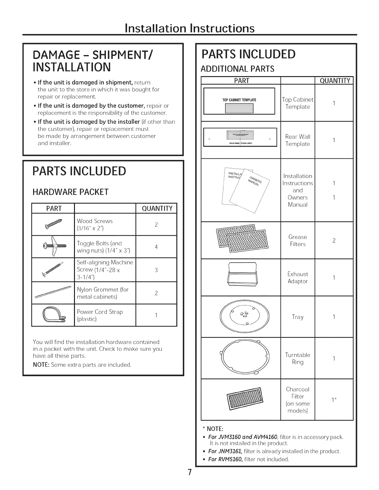
PARTS INCLUDED
HARDWARE PACKET
PART QUANTITY
Wood Screws
(3/16"x 2") 2
Toggle Bolts (and
wing nuts)(1/4" x 3") 4
Self-aligning Machine
Screw (1/4"-28 x 3
3-1/4")
jNylon Grommet (for
metal cabinets) 2
Power Cord Strap
(plastic) 1
You will find the installation hardware contained
in a packet with the unit, Check to make sure you
have all these parts,
NOTE: Some extra parts are included,
PARTS INCLUDED
ADDITIONAL PARTS
PART QUANTITY
[
TOPCABINETTEMPLATE
1
1
Top Cabinet
Template
, Rear Wall
Template
Installation
Instructions
and
Owners
Manual
Grease
Filters
Exhaust
Adaptor
Tray
Turntable
Ring
Charcoal
Filter
(on some
models)
1
1
* NOTE:
.For JVM3160 and AVM4160, filter is in accessory pack,
It is not installed in the product,
.For JNM3161, filter is already installed in the product,
.For RVM5160, filter not included,
7

Installation Instructions
MOUNTING SPACE
66" or
more from
the floor
to the
top of the
microwave
oven
........ Bottom edge of
cabinet needs to
be 30" or more
from the cooking
surface
Backsplash
NOTES:
• The space between the cabinets must be 30" wide
and free of obstructions,
• If the space between the cabinets is greater than
30", a Filler Panel Kit may be used to fill in the gap
between the microwave oven and the cabinets,
Your Owner's Manual contains the kit number for
your model,
This microwave oven is for installation over ranges
up to 36" wide,
If you are going to vent your microwave oven to the
outside, see Hood Exhaust Section for exhaust duct
preparation,
When installing the microwave oven beneath
smooth, flat cabinets, be careful to follow the
instructions on the top cabinet template for power
cord clearance,
• Maximum cabinet depth above and beside the unit
is 123A".
. For models setup in Recirc Exhaust: Do not allow
cabinetry or other objects to block the airflow of the
vent,
. The product should not be installed over any cooktop
or range with a combined BTU greater than 60,000
BTU,
8
Installation Instructions
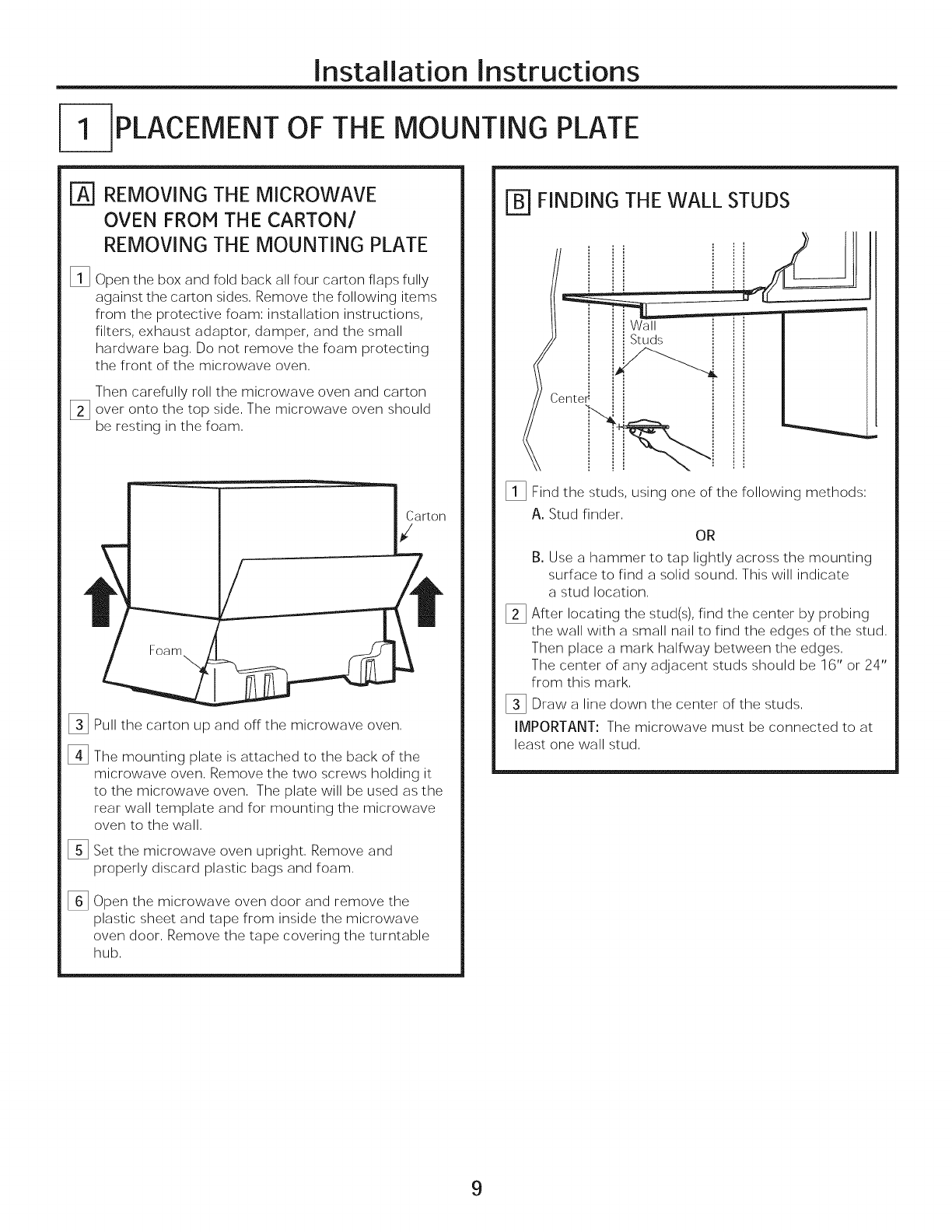
--]PLACEMENT OF THE MOUNTING PLATE
%REMOVING THE MICROWAVE
OVEN FROM THE CARTON/
REMOVING THE MOUNTING PLATE
%Open the box and fold back all four carton flaps fully
against the carton sides, Remove the following items
from the protective foam; installation instructions,
filters, exhaust adaptor, damper, and the small
hardware bag, Do not remove the foam protecting
the front of the microwave oven,
Then carefully roll the microwave oven and carton
_] over onto the top side, The microwave oven should
be resting in the foam,
arton
Foam
%
%
%
%
Pull the carton up and off the microwave oven,
The mounting plate is attached to the back of the
microwave oven. Remove the two screws holding it
to the microwave oven. The plate will be used as the
rear wall template and for mounting the microwave
oven to the wall.
Set the microwave oven upright, Remove and
properly discard plastic bags and foam,
Open the microwave oven door and remove the
plastic sheet and tape from inside the microwave
oven door, Remove the tape covering the turntable
hub,
FINDING THE WALL STUDS
t Wall
I_ Find the studs, using one of the following methods:
A. Stud finder.
OR
B. Use a hammer to tap lightly across the mounting
surface to find a solid sound. This will indicate
a stud location.
I_ After locating the stud(s), find the center by probing
the wall with a small nail to find the edges of the stud.
Then place a mark halfway between the edges.
The center of any adjacent studs should be 16" or 24"
from this mark.
I_Draw line down the of the studs.
acenter
IMPORTANT: The microwave must be connected to at
least one wall stud.
9
Installation Instructions
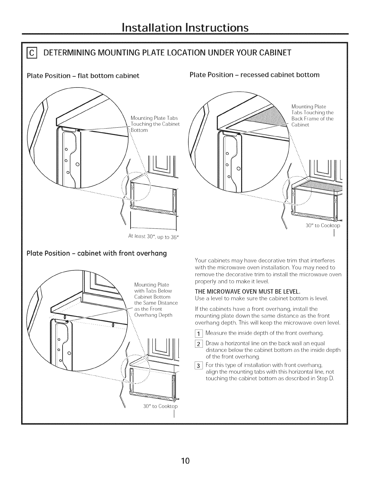
DETERMINING MOUNTING PLATE LOCATION UNDER YOUR CABINET
Plate Position - flat bottom cabinet Plate Position - recessed cabinet bottom
Mounting Plate Tabs
_Touching the Cabinet
'.Bottom
Mounting Plate
Tabs Touching the
Back Frame of the
Cabinet
At least 30", up to 36"
30" to Cooktop
I
Plate Position - cabinet with front overhang
o
Mounting Plate
with Tabs Below
Cabinet Bottom
the Same Distance
Front
Overhang Depth
30" to Cooktop
I
Your cabinets may have decorative trim that interferes
with the microwave oven installation. You may need to
remove the decorative trim to install the microwave oven
properly and to make it level.
THE MICROWAVE OVEN MUST BELEVEL.
Use a level to make sure the cabinet bottom is level,
If the cabinets have a front overhang, install the
mounting plate down the same distance as the front
overhang depth. This will keep the microwave oven level.
_i_ Measure the inside depth of the front overhang.
[_ Draw a horizontal line on the back wall an equal
distance below the cabinet bottom as the inside depth
of the front overhang.
[_ For this type of installation with front overhang,
align the mounting tabs with this horizontal line, not
touching the cabinet bottom as described in Step D.
10
Installation Instructions
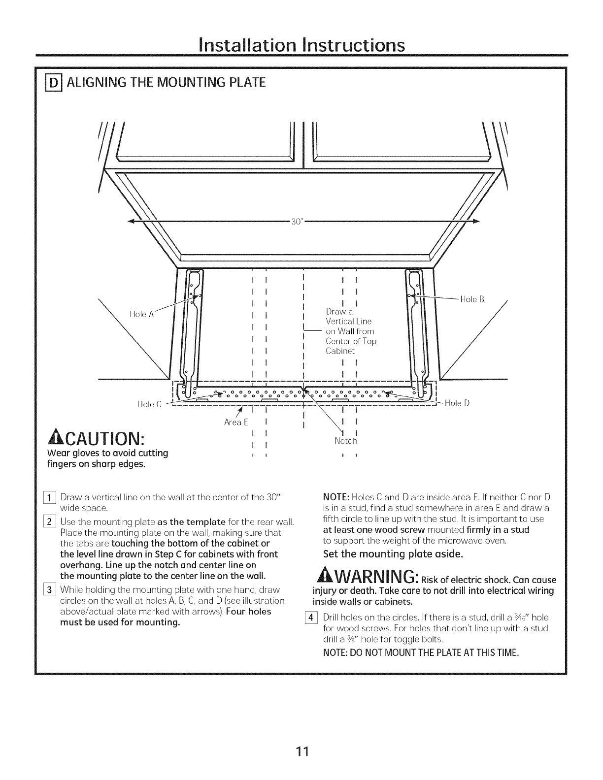
ALIGNING THE MOUNTING PLATE
Hole C
CAUTION:
Wear gloves to avoid cutting
fingers on sharp edges.
I I
I I
I I
Draw a
Vertical Line
-- on Wall from
Center of Top
Cabinet
I I
I I
f
Area E
I
I
I
I I
I I
I
Notch
I I
Hole B
Hole D
_i_ Draw a vertical line on the wall at the center of the 30"
wide space,
[]Use the mounting plate as the template for the rear wall,
Place the mounting plate on the wall, making sure that
the tabs are touching the bottom of the cabinet or
the level line drawn in Step C for cabinets with front
overhang. Line up the notch and center line on
the mounting plate to the center line on the wall.
[] While holding the mounting plate with one hand, draw
circles on the wall at holes A, B, C, and D (see illustration
above/actual plate marked with arrows), Four holes
must be used for mounting.
NOTE: Holes C and D are inside area E, If neither C nor D
is in a stud, find a stud somewhere in area E and draw a
fifth circle to line up with the stud, It is important to use
at least one wood screw mounted firmly in a stud
to support the weight of the microwave oven,
Set the mounting plate aside,
AWARN ING: iskofelectricshock.Cancause
injury or death. Take care to not drill into electrical wiring
inside walls or cabinets.
_!_ Drill holes on the circles, If there is a stud, drill a _U' hole
for wood screws, For holes that don't line up with a stud,
drill a 5A" hole for toggle bolts,
NOTE: DO NOT MOUNT THE PLATE AT THIS TIME.
11
Installation Instructions
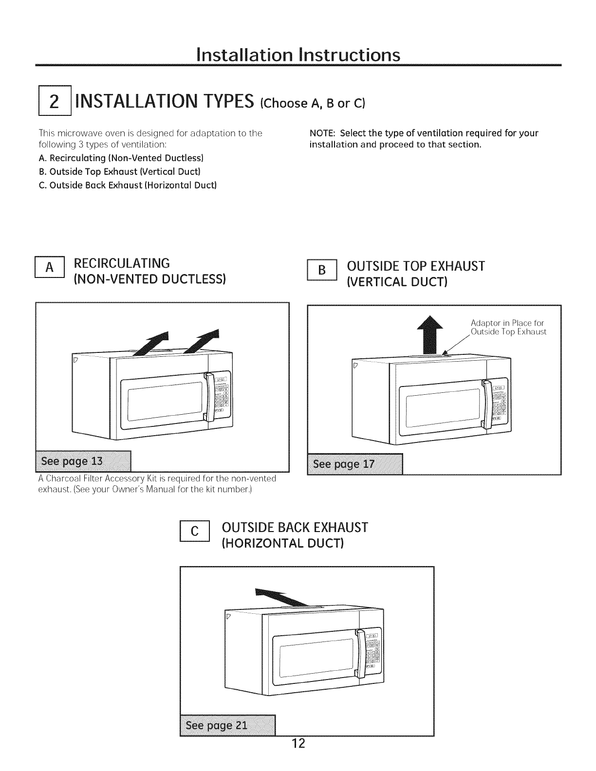
-2-IINSTALLATIONTYPES {ChooseA,B or C}
This microwave oven is designed for adaptation to the
following 3 types of ventilation:
A. Recirculating (Non-Vented Ductless}
B. Outside Top Exhaust (Vertical Duct}
C. Outside Back Exhaust IHorizontal Duct}
NOTE: Select the type of ventilation required for your
installation and proceed to that section.
-_ RECIRCULATING
{NON-VENTED DUCTLESS) OUTSIDE TOP EXHAUST
{VERTICAL DUCT)
Adaptor in Place for
Outside Top Exhaust
A Charcoal Filter Accessory Kit is required for the non-vented
exhaust, (See your Owner's Manual for the kit number,)
OUTSIDE BACK EXHAUST
{HORIZONTAL DUCT)
12
Installation Instructions
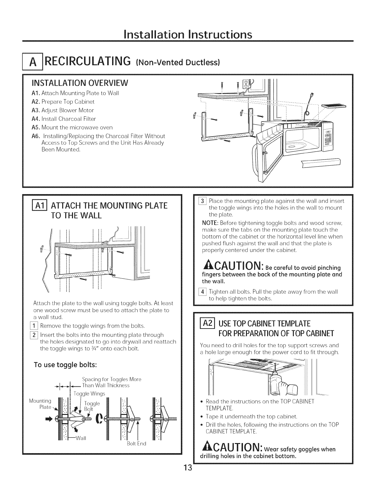
RECIRCULATING (Non-Vented Ductless)
INSTALLATION OVERVIEW
A1, Attach Mounting Plate to Wall
A2. Prepare Top Cabinet
A3. Adjust Blower Motor
A4. Install Charcoal Filter
A5. Mount the microwave oven
A6. Installing/Replacing the Charcoal Filter Without
Access to Top Screws and the Unit Has Already
Been Mounted.
f
ATTACH THE MOUNTING PLATE
TO THE WALL
Attach the plate to the wall using toggle bolts. At least
one wood screw must be used to attach the plate to
a wall stud.
_!_ Remove the toggle wings from the bolts.
[_ Insert the bolts into the mounting plate through
the holes designated to go into drywall and reattach
the toggle wings to ¾" onto each bolt.
To use toggle bolts:
Spacing for Toggles More
-_-,--_i-"--=- Than Wall Thickness
i Toggle Wings
Bolt End
[_ Place the mounting plate against the wall and insert
the toggle wings into the holes in the wall to mount
the plate.
NOTE: Before tightening toggle bolts and wood screw,
make sure the tabs on the mounting plate touch the
bottom of the cabinet or the horizontal level line when
pushed flush against the wall and that the plate is
properly centered under the cabinet.
Ar, al i-r,r_R,
Bl_.w_'_U||g|_: Be careful to avoid pinching
fingers between the back of the mounting plate and
the wall.
[] Tighten all bolts. Pull the plate away from the wall
to help tighten the bolts.
13
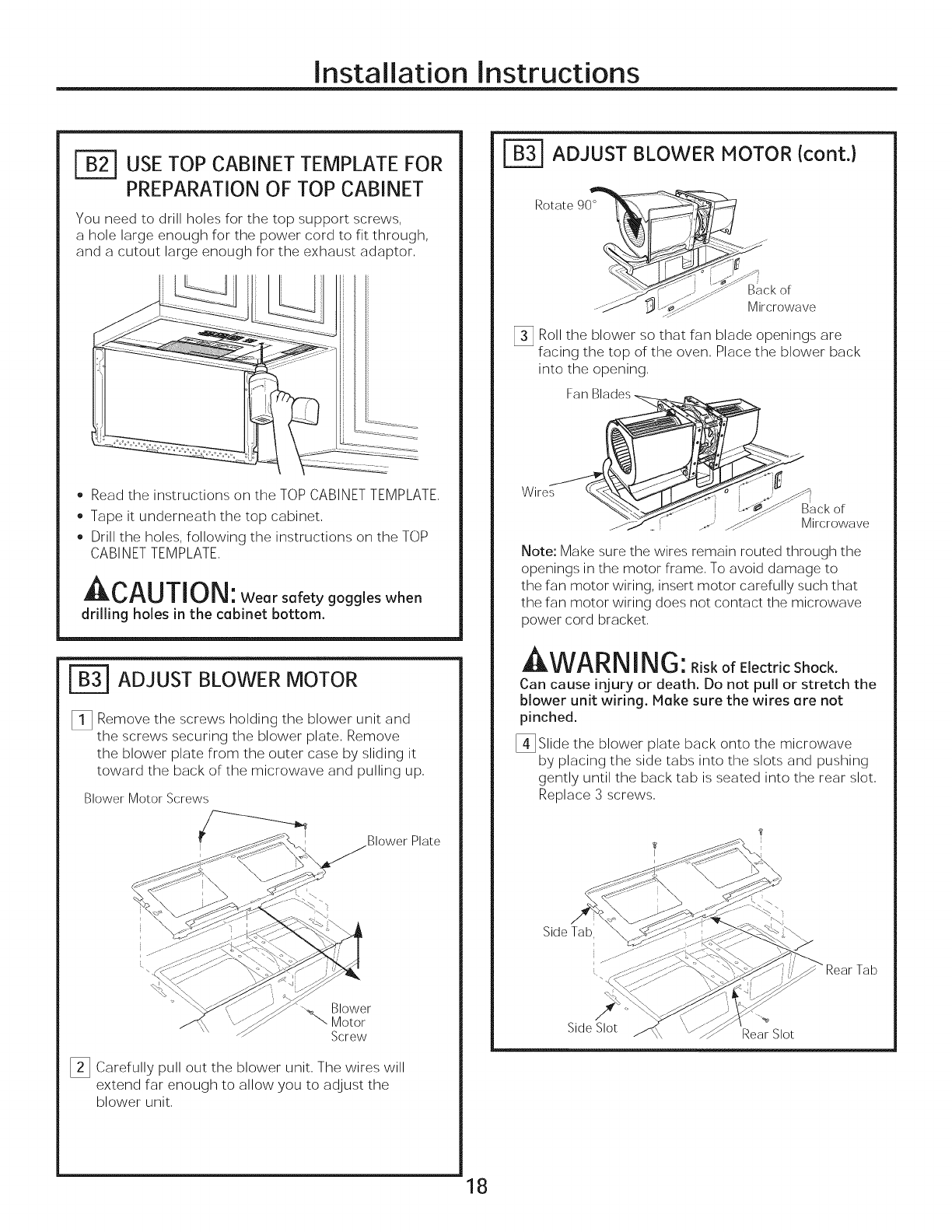
r_ USETOPCABINETTEMPLATE
FORPREPARATIONOFTOPCABINET
You need to drill holes for the top support screws and
a hole large enough for the power cord to fit through.
• Read the instructions on the TOP CABINET
TEMPLATE.
• Tape it underneath the top cabinet.
• Drill the holes, following the instructions on the TOP
CABINET TEMPLATE.
_L_'lU||g|_ : Wear safety goggles when
drilling holes in the cabinet bottom.
Installation Instructions
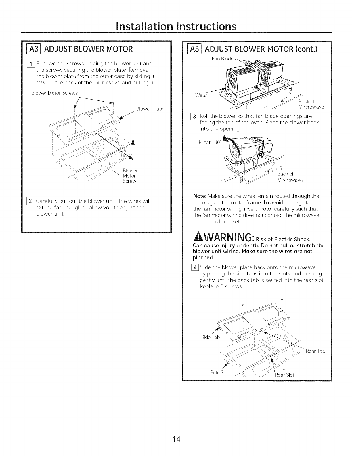
ADJUST BLOWER MOTOR
_1_ Remove the screws holding the blower unit and
the screws securing the blower plate, Remove
the blower plate from the outer case by sliding it
toward the back of the microwave and pulling up,
Blower Motor Screws
Blower Plate
Blower
"N... Motor
Screw
[] Carefully pull out the blower unit, The wires will
extend far enough to allow you to adjust the
blower unit,
ADJUST BLOWER MOTOR (cont.)
Fan Blades_ ,=__
[] Roll the blower so that fan blade openings are
facing the top of the oven, Place the blower back
into the opening,
Rotate 90°
........B_ckor
...._ #$1 Mircrowave
Note: Make sure the wires remain routed through the
openings in the motor frame, To avoid damage to
the fan motor wiring, insert motor carefully such that
the fan motor wiring does not contact the microwave
power cord bracket,
AI_IAr_K,IK,r"
LIIL VVt_KI_! I I_IVj: Risk of ElectricShock.
Can cause injury or death. Do not pull or stretch the
blower unit wiring. Make sure the wires are not
pinched.
[_Slide the blower plate back onto the microwave
by placing the side tabs into the slots and pushing
gently until the back tab is seated into the rear slot,
Replace 3 screws,
Rear Tab
Side Slot Rear Slot
14
Installation Instructions
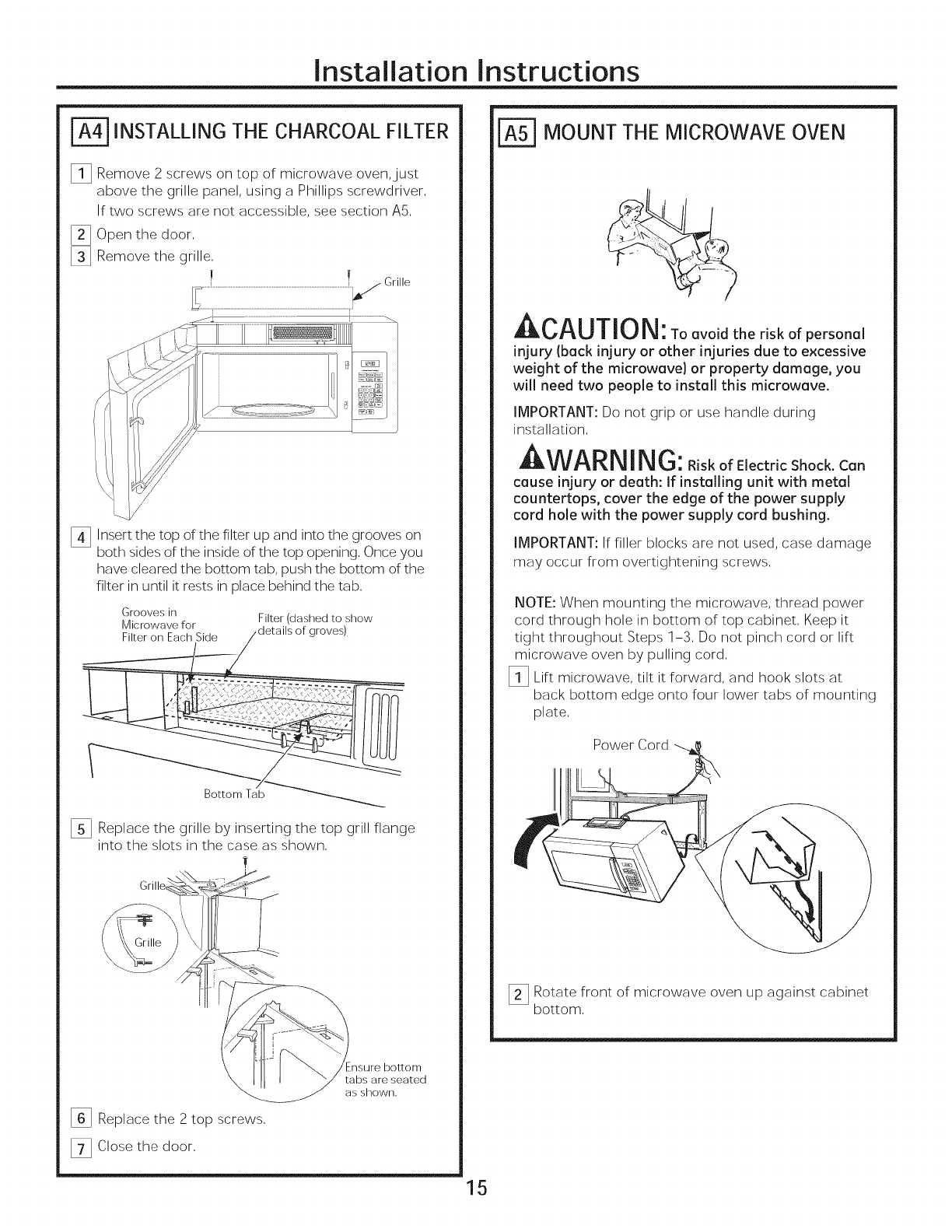
INSTALLING THE CHARCOAL FILTER
_!] Remove 2 screws on top of microwave oven,just
above the grille panel, using a Phillips screwdriver,
If two screws are not accessible, see section A5,
_] Open the door,
_] Remove the grille,
1 |
[_ Insert the top of the filter up and into the grooves on
both sides of the inside of the top opening, Once you
have cleared the bottom tab, push the bottom of the
filter in until it rests in place behind the tab,
Grooves in Filter (dashed to show
Microwave for
[] Replace the grille by inserting the top grill flange
into the slots in the case as shown,
_] Replace the 2 top screws,
[_ Close the door,
insure bottom
tabs are seated
as shown.
r_ MOUNT THE MICROWAVE OVEN
_.t.ul,u,_: Toevo_dther_skofpersonel
injury (beck injury or other injuries due to excessive
weight of the microwave} or property damage, you
will need two people to install this microwave.
IMPORTANT: Do not grip or use handle during
installation,
WARNING:RiskofElectricShock.Can
cause injury or death: If installing unit with metal
countertops, cover the edge of the power supply
cord hole with the power supply cord bushing.
IMPORTANT: If filler blocks are not used, case damage
may occur from overtightening screws,
NOTE: When mounting the microwave, thread power
cord through hole in bottom of top cabinet, Keep it
tight throughout Steps 1-3, Do not pinch cord or lift
microwave oven by pulling cord,
_i] Lift microwave, tilt it forward, and hook slots at
back bottom edge onto four lower tabs of mounting
plate,
Power Cord
[]Rotate front of microwave oven up against cabinet
bottom,
15
Installation Instructions
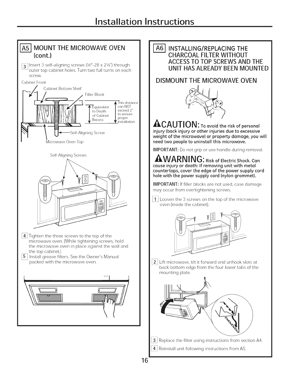
| MOUNT THE MICROWAVE OVEN
(cont.}
[] Insert 3 self-aligning screws (1A"-28 x 21A") through
outer top cabinet holes, Turn two full turns on each
screw,
Cabinet Front
Cabinet Bottom Shelf
Filler Block
This distance
--_quivalent | can NOT
I to Depth | exceed 2"
of Cabinet | to ensure
Recess _[ proper
_' installation
gning Screw
Microwave Oven Top
Self-Aligning Screws
[]Tighten the three screws to the top of the
microwave oven, (While tightening screws, hold
the microwave oven in place against the wall and
the top cabinet,)
[_ Install grease filters, See the Owner's Manual
packed with the microwave oven,
INSTALLING/REPLACING THE
CHARCOAL FILTER WITHOUT
ACCESSTO TOP SCREWSAND THE
UNIT HASALREADY BEENMOUNTED
DISMOUNT THE MICROWAVE OVEN
I CAUTION: Toovoid the risk of personal
injury (back injury or other injuries due to excessive
weight of the microwave} or property damage, you will
need two people to uninstall this microwave.
IMPORTANT: Do not grip or use handle during removal,
WARNI NG:RiskofElectricShock.Can
cause injury or death: If removing unit with metal
countertops, cover the edge of the power supply cord
hole with the power supply cord (nylon grommet).
IMPORTANT: If filler blocks are not used, case damage
may occur from overtightening screws,
_i] Loosen the 3 screws on the top of the microwave
oven (inside the cabinet),
J
I_ Lift microwave, tilt it forward and unhook slots at
back bottom edge from the four lower tabs of the
mounting plate,
16
[] Replace the filter using instructions from section A4,
[_ Reinstall unit following instructions from A5,

Installation Instructions
I-B-IOUTSIDE TOP EXHAUST{Vertical Duct)
INSTALLATION OVERVIEW
B1. Attach Mounting Plate to Wall
B2. Prepare Top Cabinet
B3. Adjust Blower Motor
B4. Install Exhaust Adaptor _" _"
BS. Mount Microwave Oven _ ,
I I
B6. Connect Ductwork ,,___
I
i
| ATTACH THE MOUNTING PLATE
TO THE WALL
A
\
C" D
Attach the plate to the wall using toggle bolts. At least
one wood screw must be used to attach the plate to
a wall stud. Recommended locations on the mounting
plate are indicated by A, B, C and D.
_!_ Remove the toggle wings from the bolts.
_ Insert the bolts into the mounting plate through
the holes designated to go into drywall and reattach
the toggle wings to ¾" onto each bolt.
17
To use toggle bolts:
Spacing for Toggles More
÷l_"-_i_---Than Wall Thickness
I
Mounting ]Toggle Wings
Plate,
Mounting Plate Bolt End
Insert the toggle wings into the holes in the wall and
place the mounting plate against the wall.
NOTE: Before tightening toggle bolts and wood screw,
make sure the tabs on the mounting plate touch the
bottom of the cabinet when pushed flush against the
wall and that the plate is properly centered under the
cabinet.
JIIk_I-_U/IUI_: Be careful to avoid pinching
fingers between the back of the mounting plate and
the wall.
[_ Tighten all bolts. Pull the plate away from the wall
to help tighten the bolts.
Installation Instructions
USE TOP CABINET TEMPLATE FOR
PREPARATION OF TOP CABINET
You need to drill holes for the top support screws,
a hole large enough for the power cord to fit through,
and a cutout large enough for the exhaust adaptor.
• Read the instructions on the TOP CABINET TEMPLATE.
•Tape it underneath the top cabinet.
•Drill the holes, following the instructions on the TOP
CABI NET TEMPLATE.
Ar, AI ITl_l
Jl_P_U|I U|_I: Wear safety goggles when
drilling holes in the cabinet bottom.
| ADJUST BLOWER MOTOR
[] Remove the screws holding the blower unit and
the screws securing the blower plate. Remove
the blower plate from the outer case by sliding it
toward the back of the microwave and pulling up.
Blower Motor Screws
IBlower Plate
Blower
"_"- Motor
Screw
I_] Carefully pull out the blower unit. The wires will
extend far enough to allow you to adjust the
blower unit.
r_ ADJUST BLOWER MOTOR (cont.)
O: ...s _-" Back of
._ i f.%_-z
--.-_._s_" Mlrcrowave
13] Roll the blower so that fan blade openings are
facing the top of the oven. Place the blower back
into the opening.
Fan Blades
Wire<_ 7 _I
Note: Make sure the wires remain routed through the
openings in the motor frame. To avoid damage to
the fan motor wiring, insert motor carefully such that
the fan motor wiring does not contact the microwave
power cord bracket.
WARNING:.iskofElectricShock.
Can cause injury or death. Do not pull or stretch the
blower unit wiring. Hake sure the wires are not
pinched.
[_]Slide the blower plate back onto the microwave
by placing the side tabs into the slots and pushing
gently until the back tab is seated into the rear slot.
Replace 3 screws.
I
Tab
Side Slot Rear Slot
18
Installation Instructions
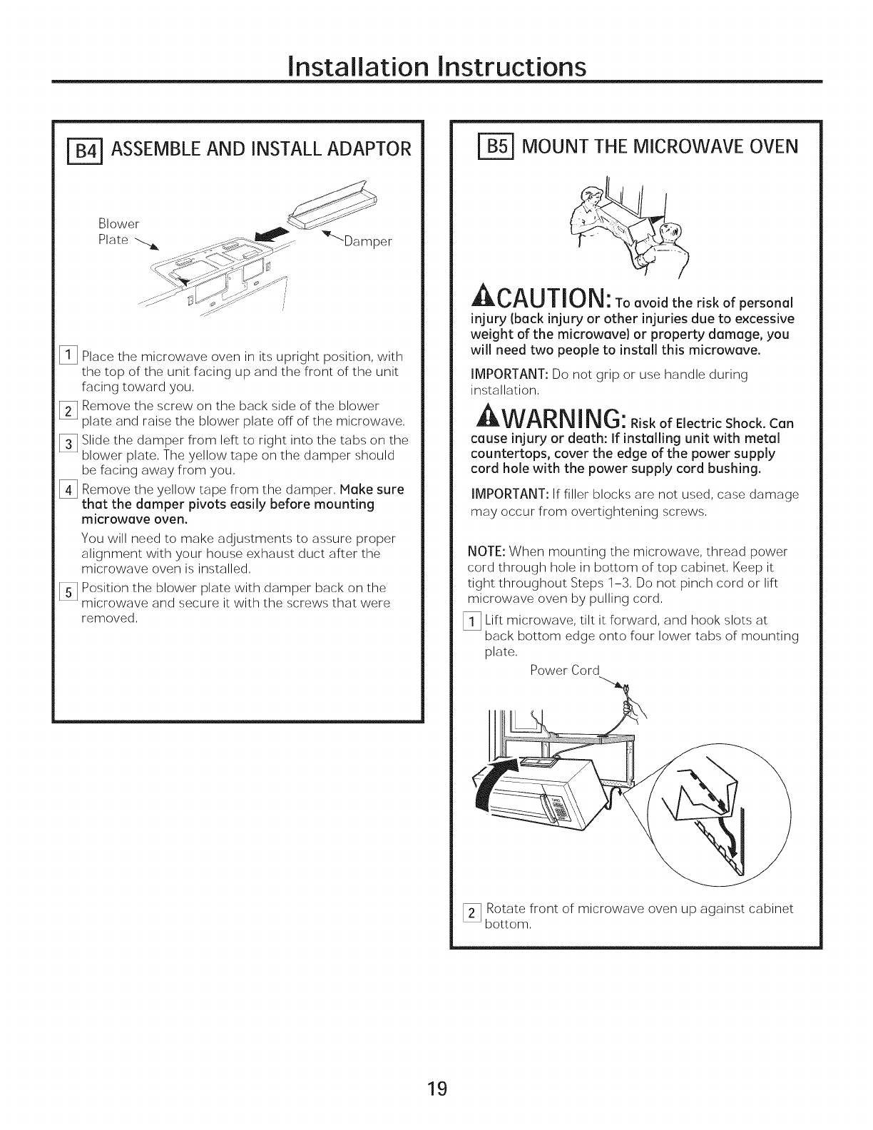
ASSEMBLE AND INSTALL ADAPTOR
_l_ Place the microwave oven in its upright position, with
the top of the unit facing up and the front of the unit
facing toward you,
Remove the screw on the back side of the blower
plate and raise the blower plate off of the microwave,
_ Slide the damper from left to right into the tabs on the
blower plate, The yellow tape on the damper should
be facing away from you,
[_ Remove the yellow tape from the damper, Make sure
that the damper pivots easily before mounting
microwave oven.
You will need to make adjustments to assure proper
alignment with your house exhaust duct after the
microwave oven is installed,
Position the blower plate with damper back on the
microwave and secure it with the screws that were
removed,
MOUNT THE MICROWAVE OVEN
, CAUTION: _o avoid the risk of personal
injury (back injury or other injuries due to excessive
weight of the microwave) or property damage, you
will need two people to install this microwave.
IMPORTANT: Do not grip or use handle during
installation,
AWARNING: RiskofElectricShock.Can
cause injury or death: If installing unit with metal
countertops, cover the edge of the power supply
cord hole with the power supply cord bushing.
IMPORTANT: If filler blocks are not used, case damage
may occur from overtightening screws,
NOTE: When mounting the microwave, thread power
cord through hole in bottom of top cabinet, Keep it
tight throughout Steps 1-3, Do not pinch cord or lift
microwave oven by pulling cord,
_l_ Lift microwave, tilt it forward, and hook slots at
back bottom edge onto four lower tabs of mounting
plate,
Power Cord
_ Rotate front of microwave oven up against cabinet
bottom,
19
Installation Instructions
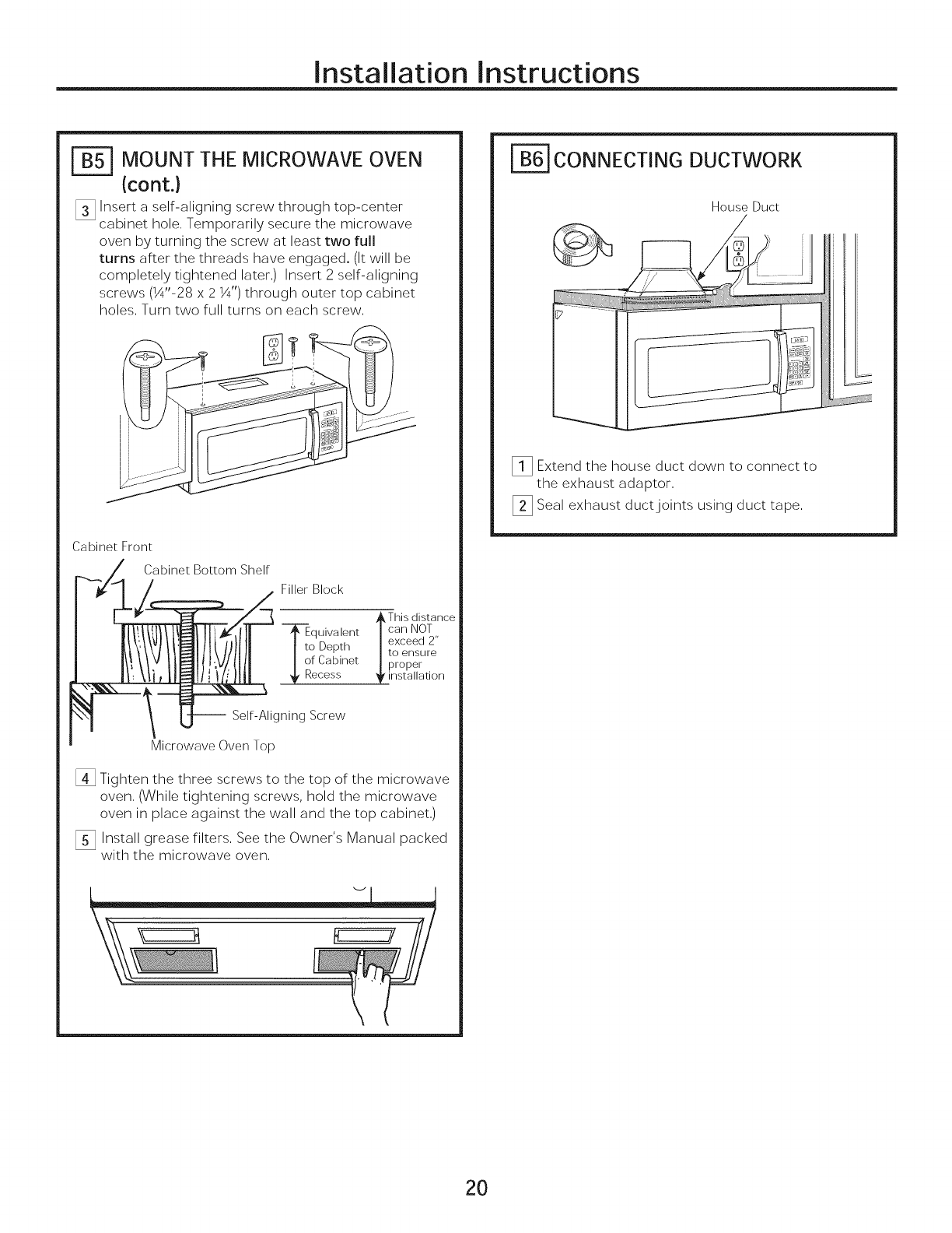
| MOUNT THE MICROWAVE OVEN
{cont.)
[] Insert a self-aligning screw through top-center
cabinet hole, Temporarily secure the microwave
oven by turning the screw at least two full
turns after the threads have engaged, (It will be
completely tightened later,) Insert 2 self-aligning
screws (W'-28 x 21¼,,)through outer top cabinet
holes, Turn two full turns on each screw,
J
J
Cabinet Front
Cabinet Bottom Shelf
Filler Block
_. This distance
J_quivalent |can NOT
I to Depth |exceed 2"
to ensure
I of Cabinet | proper
!_' Recess _ installation
-- Self-Aligning Screw
Microwave Oven Top
[] Tighten the three screws to the top of the microwave
oven, (While tightening screws, hold the microwave
oven in place against the wall and the top cabinet,)
I_3 Install grease filters, See the Owner's Manual packed
with the microwave oven,
| CONNECTING DUCTWORK
House Duct
[]Extend the house duct down to connect to
the exhaust adaptor,
_] Seal exhaust duct joints using duct tape,
2O
Installation Instructions
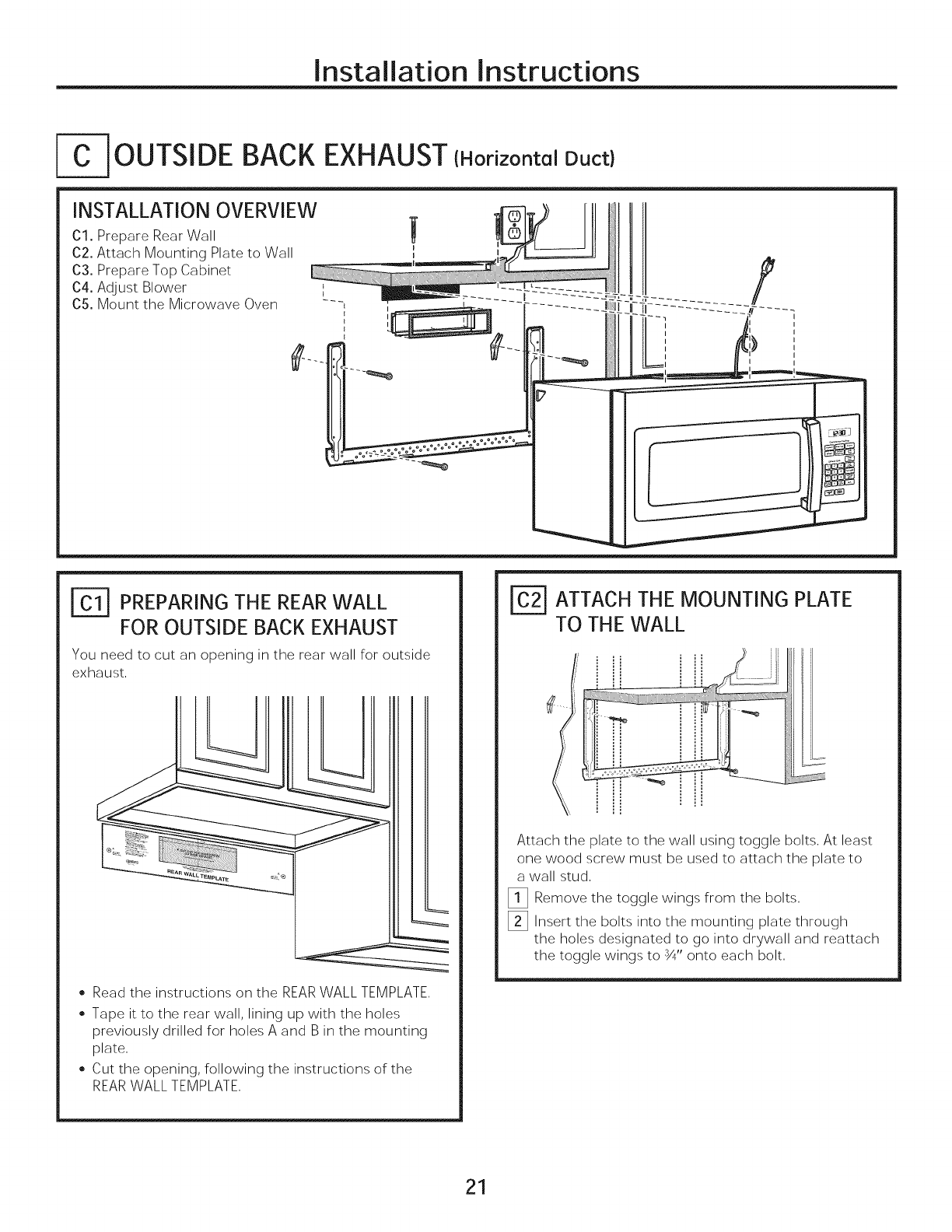
- OUTSIDE BACK EXHAUST{Horizontal Duct)
INSTALLATION OVERVIEW
Cl. Prepare Rear Wall
02. Attach Mounting Plate to Wall
03. Prepare Top Cabinet
C4. Adjust Blower
05. Mount the Microwave Oven
PREPARING THE REAR WALL
FOR OUTSIDE BACK EXHAUST
You need to cut an openinginthe rear wallforoutside
exhaust,
• Read the instructions on the REAR WALL TEMPLATE,
• Tape it to the rear wall, lining up with the holes
previously drilled for holes A and B in the mounting
plate,
• Cut the opening, following the instructions of the
REARWALL TEMPLATE,
[_ ATTACH THE MOUNTING PLATE
TO THE WALL
! __ii_i_ii
: i ...........-_ iii/ i i
Attach the plate to the wall using toggle bolts, At least
one wood screw must be used to attach the plate to
a wall stud,
_!] Remove the toggle wings from the bolts,
[]Insert the bolts into the mounting plate through
the holes designated to go into drywall and reattach
the toggle wings to ¾" onto each bolt,
21
Installation Instructions
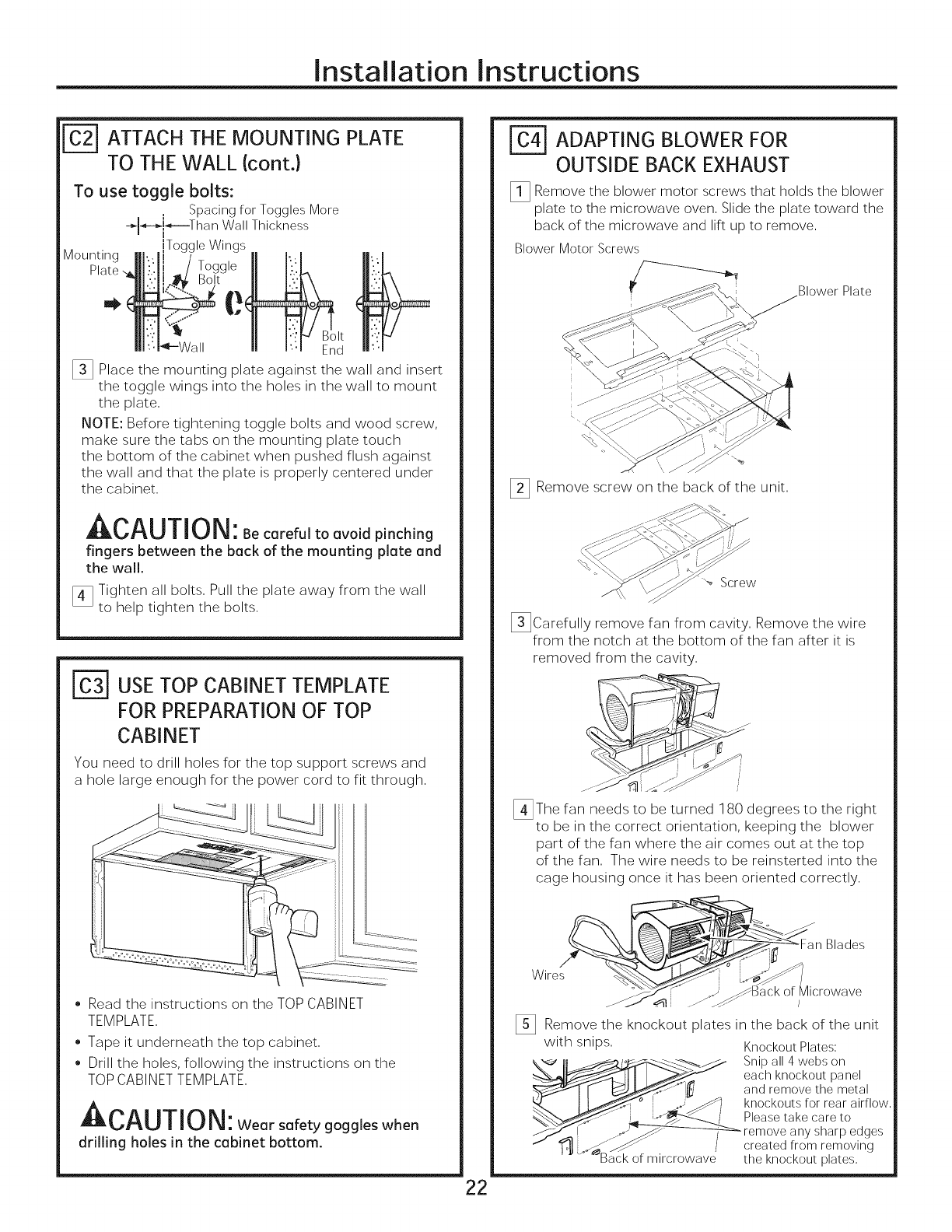
r_ ATTACH THE MOUNTING PLATE
TO THE WALL (cont.}
Mounting
To use toggle bolts:
Spacing for Toggles More
-_-_!_---Than Wall Thickness
iTogg e Wings
Togg,eII b.L
II I..:f_ Bolt
II I:q End
[] Place the mounting plate against the wall and insert
the toggle wings into the holes in the wall to mount
the plate,
NOTE: Before tightening toggle bolts and wood screw,
make sure the tabs on the mounting plate touch
the bottom of the cabinet when pushed flush against
the wall and that the plate is properly centered under
the cabinet,
Becorefoltoovoidp nch ng
fingers between the beck of the mounting plate end
the wall.
[_ Tighten all bolts, Pull the plate away from the wall
to help tighten the bolts,
['_ USETOP CABINET TEMPLATE
FOR PREPARATION OF TOP
CABINET
You need to drill holes for the top support screws and
a hole large enough for the power cord to fit through,
• Read the instructions on the TOP CABINET
TEMPLATE,
Tape it underneath the top cabinet,
Drill the holes, following the instructions on the
TOP CABINET TEMPLATE,
Jl::lLnt'_U| I U|_! : Wear safety goggles when
drilling holes in the cabinet bottom.
22
ADAPTING BLOWER FOR
OUTSIDE BACK EXHAUST
2!3 Remove the blower motor screws that holds the blower
plate to the microwave oven, Slide the plate toward the
back of the microwave and lift up to remove,
Blower Motor Screws
Blower Plate
[_] Remove screw on the back of the unit,
[_]Carefully remove fan from cavity, Remove the wire
from the notch at the bottom of the fan after it is
removed from the cavity,
> JJJ
_ ...... Ijj .1
_The fan needs to be turned ]80 degrees to the right
to be in the correct orientation, keeping the blower
part of the fan where the air comes out at the top
of the fan, The wire needs to be reinsterted into the
cage housing once it has been oriented correctly,
Blades
Wires
_Back of Microwave
/
Remove the knockout plates in the back of the unit
with snips, Knockout Plates:
, ni a,, w son
each knockout panel
r _"_ andrernovethemetal
_ knockouts for rear airflow,
Pleasetake care to
remove any sharp edges
__J /created from removing
"Back of m ircrowave the knockout plates,
Installation Instructions
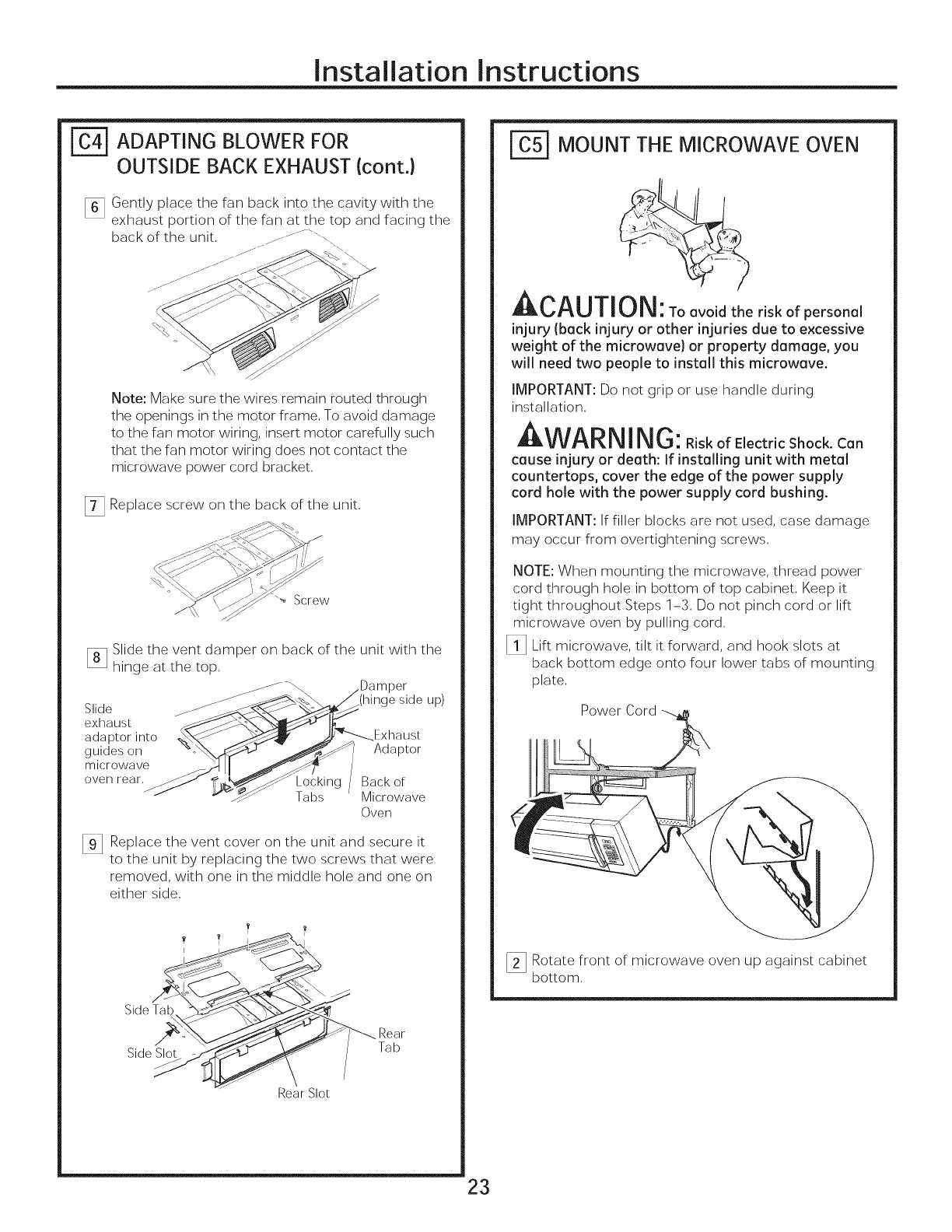
| ADAPTING BLOWER FOR
OUTSIDE BACK EXHAUST (cont.}
Note: Make sure the wires remain routed through
the openings in the motor frame, To avoid damage
to the fan motor wiring, insert motor carefully such
that the fan motor wiring does not contact the
microwave power cord bracket,
[_ Replace screw on the back of the unit,
_ Screw
Slide the vent damper on back of the unit with the
hinge at the top,
_ )or
Slide _ side up)
exhaust
adaptor into Exhaust
guides on Adaptor
microwave
oven rear, Back of
Tabs Microwave
Oven
[]Replace the vent cover on the unit and secure it
to the unit by replacing the two screws that were
removed, with one in the middle hole and one on
either side,
Side Tab
Side Slot
/
Rear
Tab
Rear Slot
r_ MOUNT THE MICROWAVE OVEN
CAUIION: Toavoidtheriskof personal
injury (back injury or other injuries due to excessive
weight of the microwave) or property damage, you
will need two people to install this microwave.
IMPORTANT: Do not grip or use handle during
installation,
AWARNING: RiskofElectricShock.Can
cause injury or death: If installing unit with metal
countertops, cover the edge of the power supply
cord hole with the power supply cord bushing.
IMPORTANT: If filler blocks are not used, case damage
may occur from overtightening screws,
NOTE: When mounting the microwave, thread power
cord through hole in bottom of top cabinet, Keep it
tight throughout Steps 1-3, Do not pinch cord or lift
microwave oven by pulling cord,
_l] Lift microwave, tilt it forward, and hook slots at
back bottom edge onto four lower tabs of mounting
plate,
Power Cord
[]Rotate front of microwave oven up against cabinet
bottom,
23
Installation Instructions
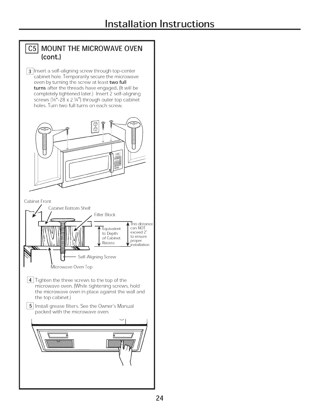
| MOUNT THE MICROWAVE OVEN
(cont.}
[]Insert a self-aligning screw through top-center
cabinet hole, Temporarily secure the microwave
oven by turning the screw at least two full
turns after the threads have engaged, (It will be
completely tightened later,) Insert 2 self-aligning
screws (_¼"-28 x 2 _') through outer top cabinet
holes, Turn two full turns on each screw,
Cabinet Front
Cabinet Bottom Shelf
Filler Block
/_ This distance
--_quivalent | can NOT
I to Depth | exceed 2"
I of Cabinet |to ensure
Recess j. proper
T installation
-- Self-Aligning Screw
Microwave Oven Top
[]Tighten the three screws to the top of the
microwave oven, (While tightening screws, hold
the microwave oven in place against the wall and
the top cabinet,)
_] Install grease filters, See the Owner's Manual
packed with the microwave oven,
24
Installation Instructions
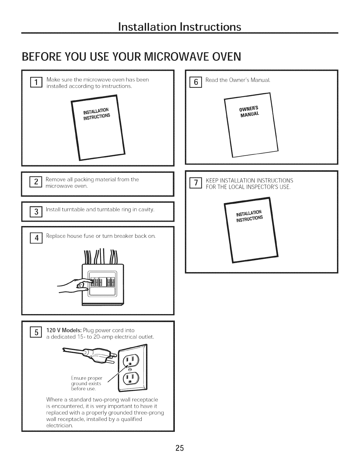
BEFOREYOU USEYOUR MICROWAVE OVEN
FT1
Make sure the microwave oven has been
installed according to instructions, r_ Read the Owner's Manual,
i
[_] emove all packing material from the
microwave oven,
r_ install turntable and turntable ring in cavity,
Replace house fuse or turn breaker back on,
i
r_ EEPINSTALLATIONINSTRUCTIONS
FORTHE LOCALINSPECTOR'SUSE,
r_ 120 v Models: Plug power cord into
a dedicated 15- to 20-amp electrical outlet,
Ensure proper
ground exists
before use,
Where a standard two-prong wall receptacle
is encountered, it is very important to have it
replaced with a properly grounded three-prong
wall receptacle, installed by a qualified
electrician,
25
Installation Instructions
26
Printed in China
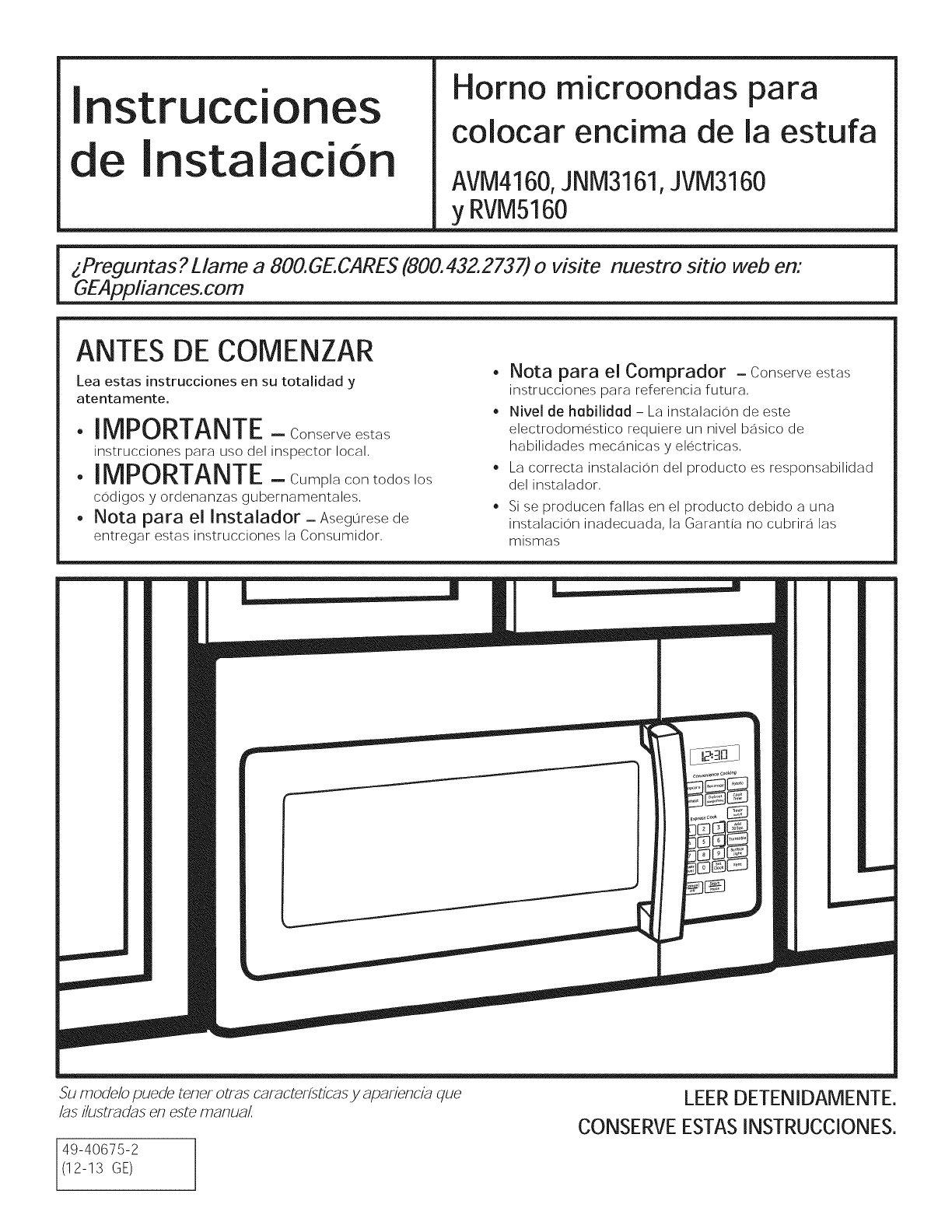
Instrucciones
de Instalacion
Homo microondas para
colocar encima de la estufa
AVM4160,JNM3161,JVM3160
y RVM5160
ANTES DE COMENZAR
Lea estas instrucciones en su totalidad y
atentamente.
•IMPORTANTE- Conserveestas
instrucciones para uso del inspector local,
•IMPORTANTE--Cumplacontodoslos
codigos y ordenanzas gubernamentales,
• Nota para el Instalador- Asegurese de
entregar estas instrucciones la Consumidor,
• Nota para el Comprador -Conserve estas
instrucciones para referencia futura,
• Nivel de habilidad - La instalacion de este
electrodomestico requiere un nivel basico de
habilidades mecanicas y electricas,
La correcta instalacion del producto es responsabilidad
del instalador,
Si se producen fallas en el producto debido a una
instalacion inadecuada, la Garantia no cubrira las
mismas
Su modelo puede tenet otras caracterfsticas yapariencia que
/as Hustradas en este manual
49-40675-2
(12-13 GE)
LEER DETENIDAMENTE.
CONSERVE ESTAS INSTRUCCIONES.
Instrucciones de InstalaciOn
CONTENIDOS
Informacion General
Instrucciones Importantes de Seguridad .................... 3
Requisitos Electricos ....................................................... 3
Herramientas Que Necesitara ....................................... 4
Campana de Escape ..................................................... 5,6
Da6o - Envio/Insta(ad6n .............................................. 7
Partes Inc(uidas ................................................................ 7
Espacio de Montaje .......................................................... 8
Guia de instalaci6n paso a paso
Colocacion de la Placa de Montaje .......................... 9-10
Retiro de la Placa de Montaje ............................. 9
B0squeda de los Montajes de Pared .................. 9
Determinacion de la Placa de Montaje ............ 10
Alineacion de la Placa de Montaje .................... 11
Tipos de Instalacion ................................................. 12-23
_ Recirculacion ................................................ 13-16
Adjunte la Placa de Montaje a la Pared .13
Preparacion del Gabinete Superior ........ 13
Ajuste el Calentador .........................................14
Como Instalar el Filtro de Carbon ...................15
Monte el Homo Microondas ............. 15, 16
Instalacion del Filtro de Carbon Sin
_ Acceso a los Tornillos Superiores 16
Escape de Salida Superior ........................... 17-20
Adjunte la Placa de Montaje a la Pared .17
Preparacion del Gabinete Superior ......... 18
Ajuste el Motor del Calentador ................. 18
Ensamble e Instale el Adaptador ............ 19
Monte el Homo Microondas ............. 19, 20
Conexion de la Tuberia ............................ 20
[_ Escape de Salida Trasero ............................ 21-24
Vision General de la Instalacion ............... 21
Preparacion de la Pared Trasera
para el Escape de Salida Trasero ............ 21
Adjunte la Placa de Montaje a la Pared .. 21, 22
Preparacion del Gabinete Superior .........22
Adaptacion del Calentador al
Escape de Salida Trasero .................... 22, 23
Monto el Homo Microondas .............. 23, 24
Antes de Usar su Horno Microondas ........................ 25
2
Instrucciones de InstalaciOn
INSTRUCCIONES IMPORTANTES DE SEGURIDAD
Un electricista calificado debera realizar un control de
la continuidad de la conexion a tierra en el receptaculo
de la pared antes de comenzar con la instalacion, a
fin de asegurar que la caja del tomacorriente este
correctamente conectada a tierra, Si no se encuentra
conectado a tierra de forma correcta, o si el receptaculo
de pared no cumple con los requisitos establecidos (bajo
REQUISITOS ELECTRICOS), se debera solicitar los servicios
de un electricista calificado para corregir cualquier
deficiencia
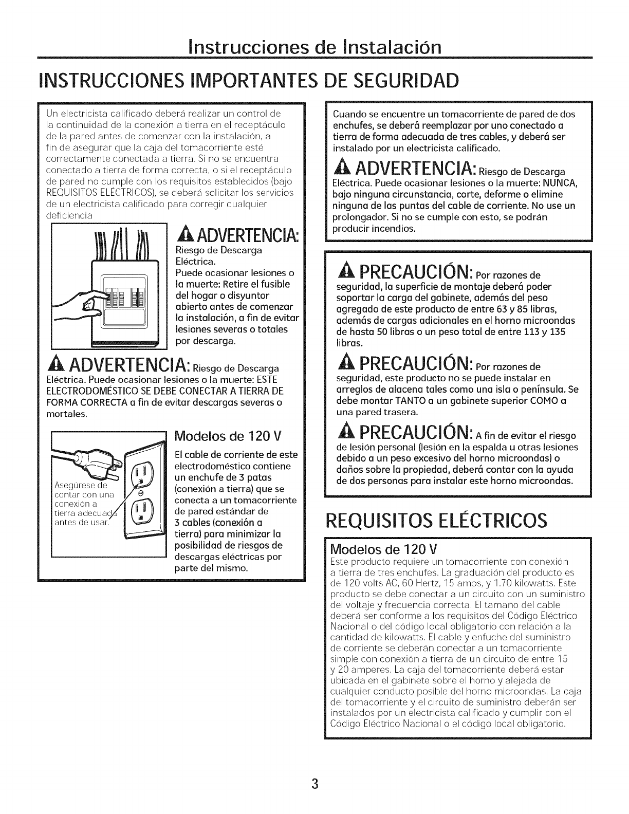
A ADVERTENCIA:
Riesgo de Descarga
Eiectrica.
Puede ocasionar iesiones o
la muerte: Retire el fusible
del hogar o disyuntor
abierto antes de comenzar
la instalaci6n, a fin de evitar
lesiones severas o totoles
par descarga.
A ADVERTENCIA:R,osgodeDescarga
Electrica. Puede ocasionar lesiones o la muerte: ESTE
ELECTRODOMESTICO SE DEBE CONECTAR A TIERRA DE
FORMA CORRECTA a fin de evitar descargas severas o
mortales.
Modelos de 120 V
El cable de corriente de este
electrodomestico contiene
un enchufe de 3 patas
(conexion a tierra) que se
conecta a un tomacorriente
de pared estandar de
3 cables (conexi6n a
tierra) para minimizar Io
posibilidad de riesgos de
descargas eiectricas par
parte dei mismo.
Cuando se encuentre un tomacorriente de pared de dos
enchufes, se debar6 reemplazar par uno conectado a
tierra de forma adecuada de tres cables, y deber6 ser
instaiado par un eiectricista caiificado.
A ADVERTENCIA: R_esgodeDescarga
Electrica. Puede ocasionar lesiones o la muerte; NUNCA,
bo]o ninguna circunstancia, carte, deforme o elimine
ninguna de las puntas del cable de corriente. No use un
prolongador. Si no se cumple con esto, se podran
producir incendios.
PRECAUCION:Parrazonesde
seguridad, la superficie de montaje deber6 poder
soportar la carga del gabinete, ademOs del peso
agregado de este producto de entre 63 y 85 libras,
ademOs de cargas adicionales en el homo microondos
de hasta 50 libras o un peso total de entre 113 y 135
libras.
A PRECAUCION:Parrazonesde
seguridad, este producto no se puede instalar en
arreglos de alacena tales coma una isla o peninsula. Se
debe montar TANTO a un gabinete superior COMO a
una pared trasera.
PRECAUCION:Afindeevitarelriesgo
de lesion personal (lesion en la espalda u otras lesiones
debido a un peso excesivo del homo microondas) o
da_os sabre la propiedad, deber6 contar con la ayuda
de dos personas para instalar este homo microondas.
REQUISITOS ELECTRICOS
Modelos de 120 V
Este producto requiere un tomacorriente con conexion
a tierra de tres enchufes, La graduacion del producto es
de 120 volts AC, 60 Hertz, 15 amps, y 1,70 kilowatts, Este
producto se debe conectar a un circuito con un suministro
del voltaje y frecuencia correcta, El tama_o del cable
debera set conforme a los requisitos del Codigo Electrico
Nacional o del codigo local obligatorio con relacion a la
cantidad de kilowatts, El cable y enfuche del suministro
de corriente se deberan conectar a un tomacorriente
simple con conexion a tierra de un circuito de entre 15
y 20 amperes, La caja del tomacorriente debera estar
ubicada en el gabinete sabre el horno y alejada de
cualquier conducto posible del homo microondas, La caja
del tomacorriente y el circuito de suministro deberan set
instalados par un electricista calificado y cumplir con el
Codigo Electrico Nacional o el codigo local obligatorio,
3
Instrucciones de InstalaciOn
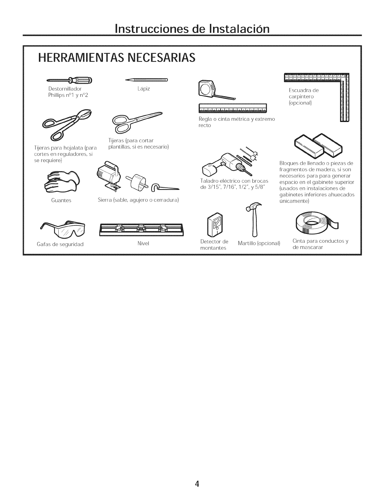
HERRAMIENTAS IklECESARIAS
Destornillador Lapiz
Phillips n°l }/n°2
Tijeras para hqjalata (para
cortes en reguladores, si
se requiere)
Guantes
Galas de seguridad
T!jeras (para cortar
plantillas, si es necesario)
Sierra (sable, agujero o cerradura)
Nivel
8£_
Lh,bl,,,JJ,L,a-d,J.,_,bJ,d,_,_,h,_,_,,_,,hP,,_,d,J
Regla o cinta metrica }/extreme
recto
Taladro electrico con brocas
de 3/15", 7/16", 1/2", }/5/8"
Escuadra de
carpintero
(opcional)
Detector de Martillo (opcional) Cinta para conductos y
montantes de mascarar
Bloques de Ilenado o piezas de
fragmentos de madera, si son
necesarios para para generar
espacio en el gabinete superior
(usados en instalaciones de
gabinetes inferiores ahuecados
Onicamente)
4
Instrucciones de Instalacion
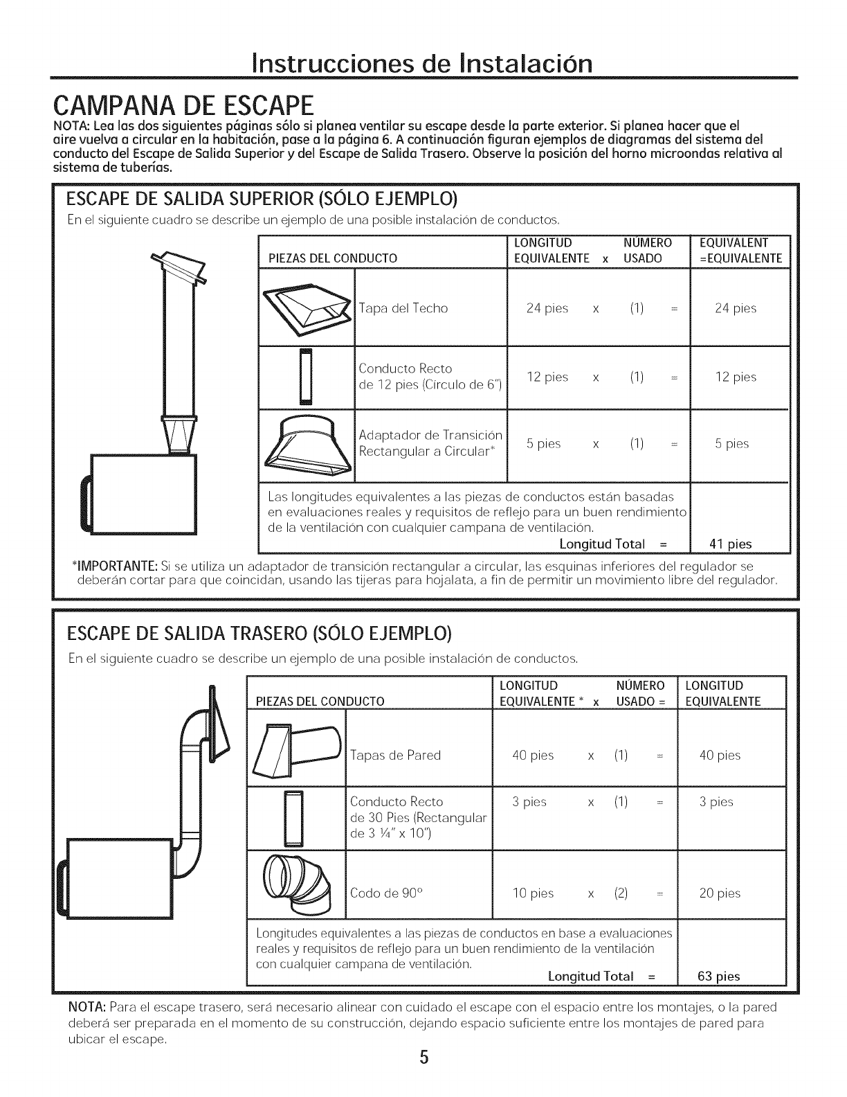
CAMPANA DE ESCAPE
NOTA: Lea las dos siguientes p6ginas s61o si planea ventilar su escape desde la parte exterior. Si planea hacer que el
aire vuelva a circular en la habitaci6n, pase a la p6gina 6. A continuaci6n figuran ejemplos de diagramas del sistema del
conducto del Escape de Salida Superior ydel Escape de Salida Trasero. Observe la posici6n del homo microondas relativa al
sistema de tuberias.
ESCAPE DE SALIDA SUPERIOR (SOLO EJEMPLO)
En el siguiente cuadro so describe un ejemplo de una posible instalacion de conductos,
LONGITUD NUMERO EQUIVALENT
_ PIEZASDEL CONDUCTO EQUIVALENTE x USADO =EQUIVALENTE
_ Tapa del Techo 24 pies x (1) = 24 pies
Conducto Recto
de 12 pies (Circulo de 6") 12 pies x (1) : 12 pies
m
-
_L Adaptador de Transicion
Rectangular a Circular* 5 pies x (1) : 5 pies
Las longitudes equivalentes alas piezas de conductos estan basadas
en evaluaciones reales y requisites de reflejo para un buen rendimiento
de la ventilacion con cualquier campana de ventilacion,
41 pies
*IMPORTANTE: Si se utiliza un adaptador de transicion rectangular a circular, las esquinas inferiores del regulador se
deberan cortar para que coincidan, usando las tijeras para hojalata, a fin de permitir un movimiento libre del regulador,
ESCAPE DE SALIDA TRASERO (SOLO EJEMPLO)
En el siguiente cuadro se describe un ejemplo de una posible instalacion de conductos,
PIEZASDEL CONDUCTO
(_ Code de 90 °
LONGITUD NOMERO LONGITUD
EQUIVALENTE* x USADO = EQUIVALENTE
40 pies x (1)Tapas de Pared
Conducto Recto
de 30 Pies (Rectangular
de3 1/4"x 10")
3 pies x (1)
10 pies x (2) :
Longitudes equivalentes a las piezas de conductos en base a evaluaciones
reales y requisites de reflejo para un buen rendimiento de la ventilacion
con cualquier campana de ventilacion, Longitud Total =
40 pies
3 pies
20 pies
63 pies
NOTA: Para el escape trasero, sera necesario alinear con cuidado el escape con el espacio entre los montajes, o la pared
debera set preparada en el memento de su construccion, dejando espacio suficiente entre los montajes de pared para
ubicar el escape, 5
Instrucciones de InstalaciOn
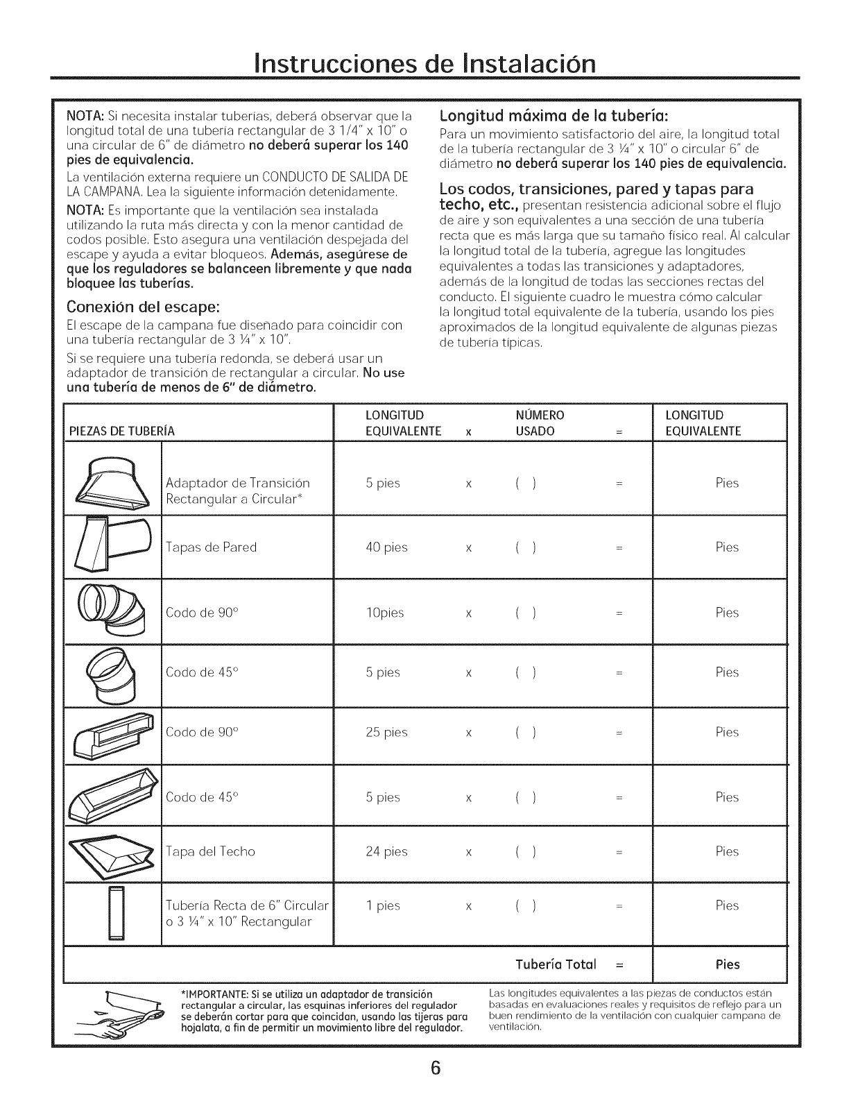
NOTA: Si necesita instalar tuberias, debera observar qua la
Iongitud total de una tuberia rectangular de 3 1/4" x 10" o
una circular de 6" de diametro no debera superar los 140
pies de equivalencia.
La ventilacion externa requiere un CONDUCTO DE SALIDA DE
LA CAMPANA, Lea la siguiente informacion detenidamente,
NOTA: Es importante qua la ventilacion sea instalada
utilizando la rata mas directa y con la manor cantidad de
codes posible, Esto asegura una ventilacion despejada del
escape y ayuda a evitar bloqueos, Ademas, asegurese de
qua los reguledores se balanceen libremente y qua nada
bloquee las tuberias.
Conexion del escape:
El escape de la campana rue dise_ado para coincidir con
una tuberia rectangular de 3 ¼"x 10",
Si se requiere una tuberia redonda, se debera usar un
adaptador de transicion de rectangular a circular, No use
una tuberia de manes de 6" de di_metro.
Longitud m6xima de la tuberia:
Para un movimiento satisfactorio del aire, la Iongitud total
de la tuberia rectangular de 3 ¼"x 10" o circular 6" de
diametro no debar6 superar los 140 pies de equivalencia.
Los codes, transiciones, pared y tapas para
techo, etc., presentan resistencia adicional sobre el flujo
de aire y son equivalentes a una seccion de una tuberia
recta qua es mas larga qua su tamale fisico real, AI calcular
la Iongitud total de la tuberia, agregue las longitudes
equivalentes a todas las transiciones y adaptadores,
ademas de la Iongitud de todas las secciones rectas del
conducto, El siguiente cuadro le muestra come calcular
la Iongitud total equivalente de la tuberia, usando los pies
aproximados de la Iongitud equivalente de algunas piezas
de tuberia tipicas,
PIEZASDE TUBERiA
de Transicion
Adaptador
Rectangular a Circular*
//'_ apas de Pared
(__ Code de 90 °
LONGITUD NOMERO
EQUIVALENTE x USADO
5 pies ( )
40 pies ( )
10pies ( )
LONGITUD
EQUIVALENTE
Pies
Pies
Pies
(_ Code de 45 ° 5 pies x ( ) = Pies
Code de 90 ° 25 pies x ( ) = Pies
_ Codode45 ° 5pies x ( ) = Pies
Tapa del Techo 24 pies x ( ) = Pies
Tuberia Recta de 6" Circular 1 pies x ( ) = Pies
o 3 1/4"x 10" Rectangular
Tuberia Total = Pies
*IHPORTANTE: Sise utiliza un adaptador de transici6n
rectangular a circular, las esquinas inferiores del regulador
se deber_n cortar para qua coincidan, usando las tijeras para
hojalata, a fin de permitir un movimiento libra del regulador.
Las longitudes equivalentes alas piezas de conductos estan
basadas en evaluaciones reales y requisites de reflejo para un
buen rendimiento de la ventilacion con cualquier campana de
ventilacion.
6

Instrucciones de InstalaciOn
DANO - ENViO/
INSTALACION
• Si la unidad se daSa durante el envio, devuelva
la unidad a la tienda donde fue comprada para su
reparacion o reemplazo.
• Si la unidad es dahada por el cliente, la reparacion
o reemplazo es responsabilidad del cliente.
• Si la unidad es daSada por el instalador (si no es
el cliente), la reparacion o reemplazo debera set
realizado pot arreglo entre el cliente y el instalador.
PARTES INCLUIDAS
PAQUETE DE PIEZAS
PARTE CANTIDAD
' Tornillos de Madera
(3/16"x 2") 2
Tornillos con resorte
y tuercas mariposa) 4
(I/4"x 3")
Tornillo de Maquina
con Auto Alineacion 3
(1/4"-28 x 3-1/4")
j Arandela Aislante
de Nylon (para 2
gabinetes metalicos)
Cordon para cablede corriente (plastico) 1
Enconrara las piezas de instalacion dentro de
un paquete con la unidad. Asegurese de que se
encuentren todas las piezas.
NOTA: Se incluyen algunas piezas adicionales.
PARTES INCLUIDAS
7
PIEZAS ADICIONALES
PARTE
TOPCABINETTEMPLATE
REA__mLL_E_pLA_t]
m.J
Plantilla del
Gabinete
Superior
Plantilla de
'_ la Pared
Trasera
Instrucciones
de
Instalacion
del Manual
del
Propietario
Filtros de
Grasa
Adaptador
del Escape
Bandeja
Anillo
del Plato
Giratorio
Filtro de
Carbon
(en algunos
modelos)
CANTIDAD
I
I
5
NOTA:
•Para JVM3160yAVM4160, el filtro esta en el paquete de
accesorios. No se encuentra instalado en el producto.
•Para JNM3161, el filtro ya se encuentra instalado en el
producto.
•Para RVM5160, el filtro no esta incluido.
Instrucciones de Instalacion
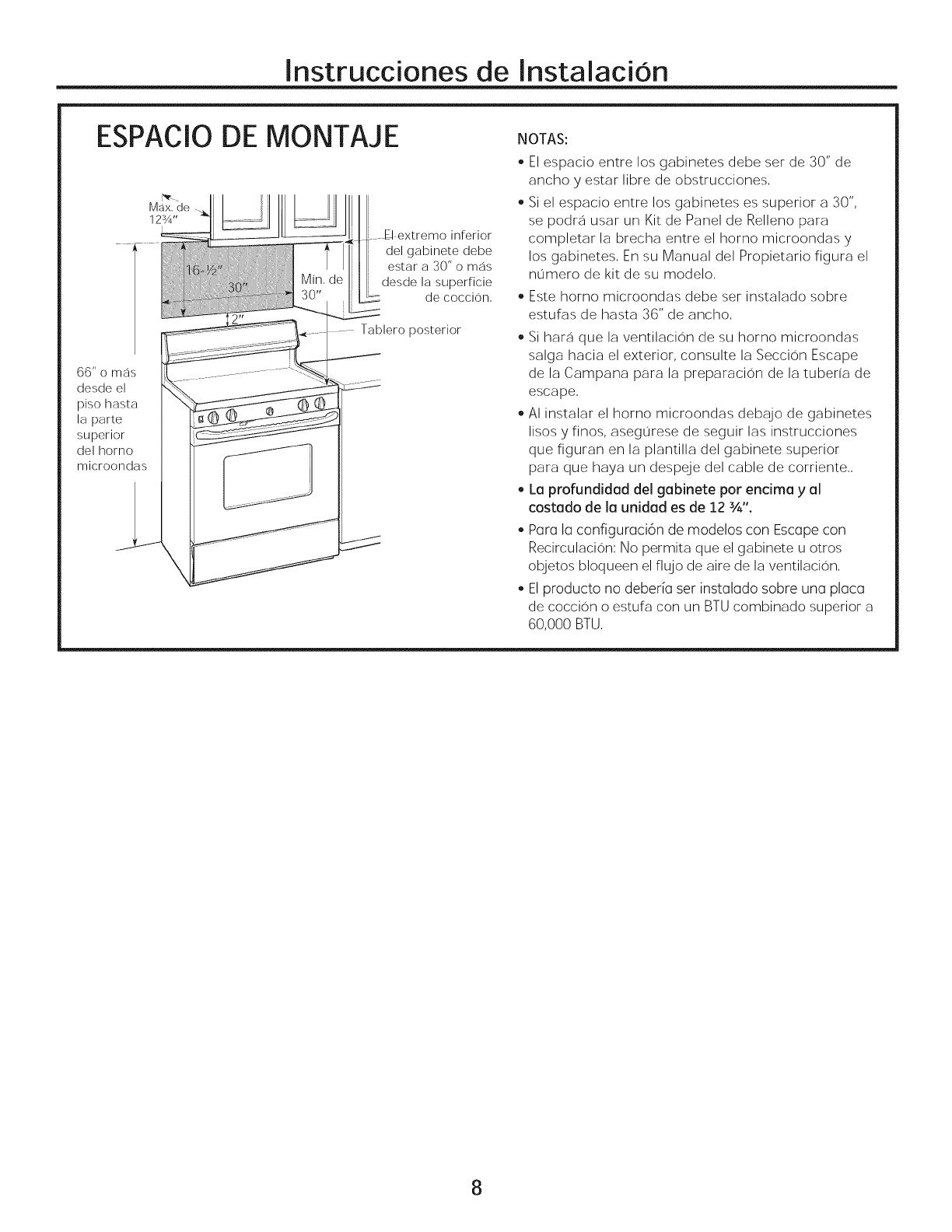
ESPACIO
M_Jx. de
12¾"
66" o mas
desde el
piso hasta
la parte
superior
del horno
microondas
DE MONTAJE
....E_extremo inferior
del gabinete debe
estar a 30" o mas
desde la superficie
de coccion,
Tablero posterior
NOTAS:
• El espacio entre los gabinetes debe ser de 30" de
ancho y estar libre de obstrucciones,
Si el espacio entre los gabinetes es superior a 30",
se podra usar un Kit de Panel de Relleno para
completar la brecha entre el homo microondas y
los gabinetes, En su Manual del Propietario figura el
numero de kit de su modelo,
Este homo microondas debe ser instalado sobre
estufas de hasta 36" de ancho,
Si hara que la ventilacion de su homo microondas
salga hacia el exterior, consulte la Seccion Escape
de la Campana para la preparacion de la tuberia de
escape,
AI instalar el homo microondas debajo de gabinetes
lisos y finos, asegurese de seguir las instrucciones
que figuran en la plantilla del gabinete superior
para que haya un despeje del cable de corriente,,
La profundidad del gabinete por encima y al
costado de la unidad es de 12 3/,,,,.
Para la configuraci6n de modelos con Escape con
Recirculacion: No permita que el gabinete u otros
objetos bloqueen el flujo de aire de la ventilacion,
El producto no deber[a ser instalado sobre una placa
de coccion o estufa con un BTU combinado superior a
60,000 BTU,
8
lnstrucciones de
-]COLOCACION DEL PLATO DE
lnstalaci6n
MONTAJE
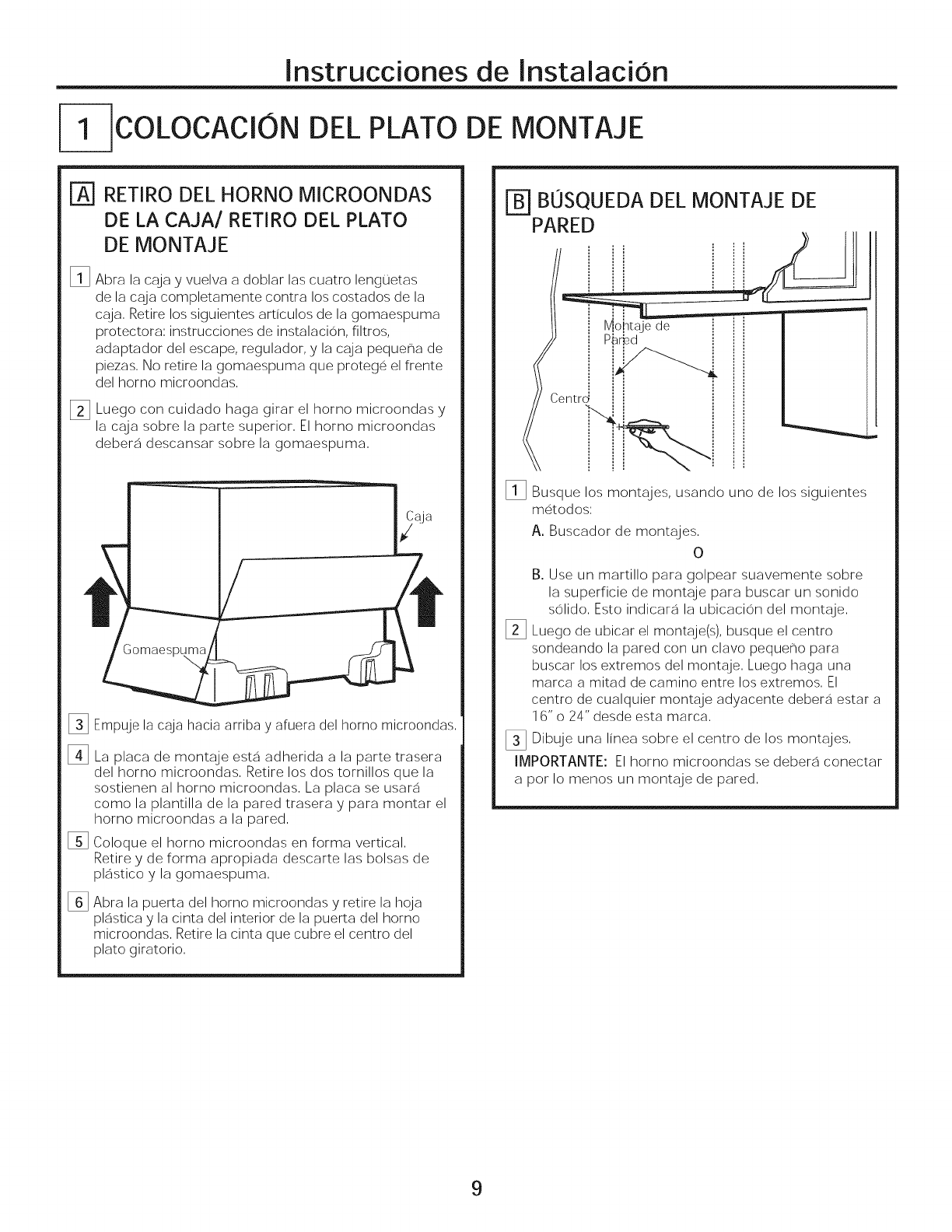
%RETIRO DEL HORNO MICROONDAS
DE LA CAJA/RETIRO DEL PLATO
DE MONTAJE
%Abra la caja y vuelva a doblar las cuatro lengLietas
de la caja completamente contra los costados de la
caja, Retire los siguientes articulos de la gomaespuma
protectora; instrucciones de instalacion, filtros,
adaptador del escape, regulador, y la caja peque_a de
piezas, No retire la gomaespuma que protege el frente
del homo microondas,
_] Luego con cuidado haga girar el homo microondas y
la caja sobre la parte superior, El homo microondas
debera descansar sobre la gomaespuma,
%
%
[]
%
Empuje la caja hacia arriba y afiuera del homo microondas,
La placa de montaje esta adherida a la parte trasera
del homo microondas, Retire los dos tornillos que la
sostienen al horno microondas, La placa se usara
como la plantilla de la pared trasera y para montar el
homo microondas a la pared,
Coloque el homo microondas en forma vertical,
Retire y de forma apropiada descarte las bolsas de
plastico y la gomaespuma,
Abra la puerta del homo microondas y retire la hoja
plastica y la cinta del interior de la puerta del homo
microondas, Retire la cinta que cubre el centro del
plato giratorio,
[_ BOSQUEDA DEL MONTAJE DE
PARED
le IVjo[ltqje de
ntrd P_
I_ Busque los montajes, usando uno de los siguientes
m_S.todos:
A. Buscador de montajes,
O
B. Use un martillo para golpear suavemente sobre
la superficie de montaje para buscar un sonido
solido, Esto indicara la ubicacion del montaje,
I_ Luego de ubicar el montaje(s), busque el centro
sondeando la pared con un clavo pequeno para
buscar los extremos del montaje, Luego haga una
marca a mitad de camino entre los extremos, El
centro de cualquier montaje adyacente debera estar a
16" o 24" desde esta marca,
[] Dibuje una linea sobre el centro de los montajes,
IMPORTANTE: El homo microondas se debera conectar
a pot Io menos un montaje de pared,
9
Instrucciones de Instalaci6n
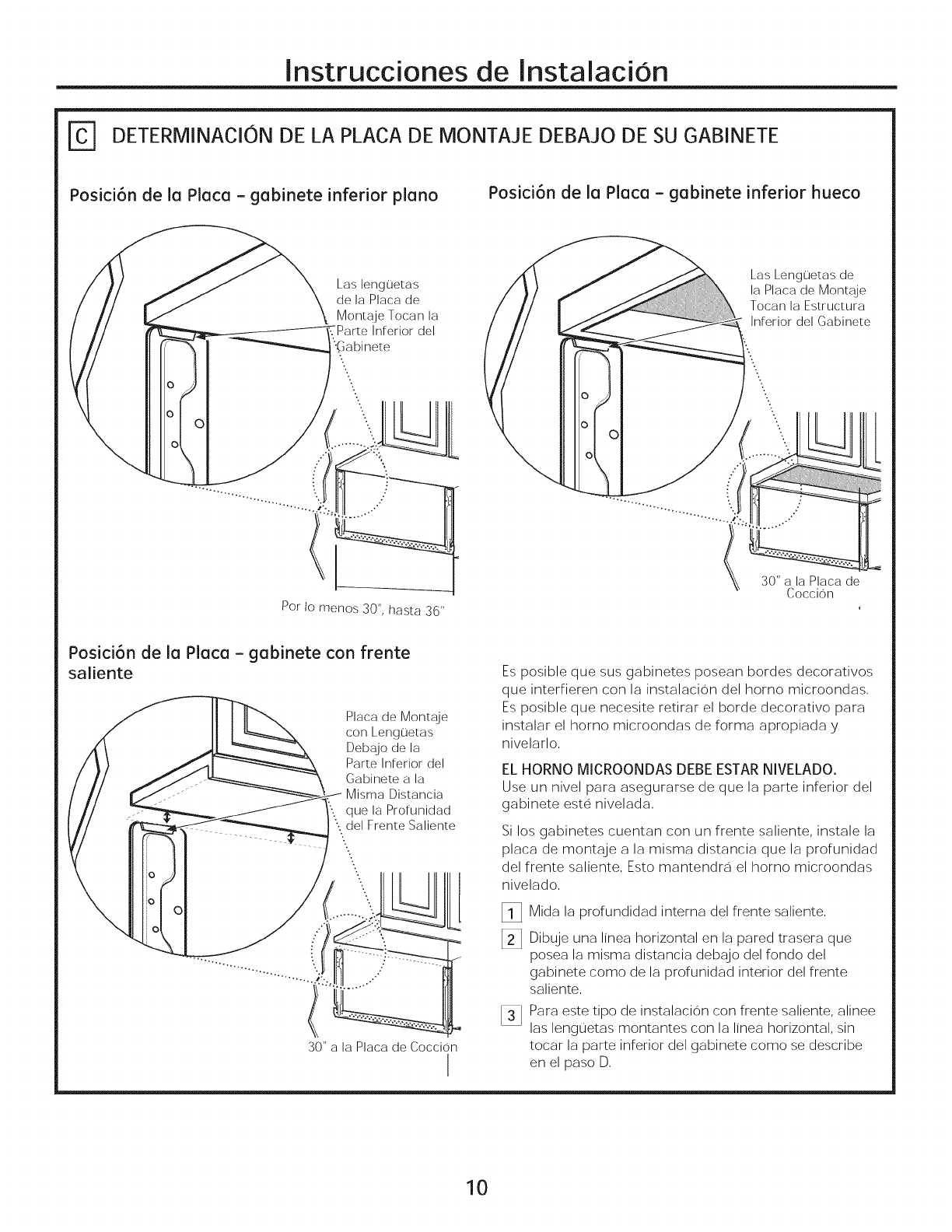
DETERMINACION DE LA PLACA DE MONTAJE DEBAJO DE SU GABINETE
Posici6n de la Placa - gabinete inferior piano Posici6n de la Placa - gabinete inferior hueco
Las lenguetas
de la Placa de
Montaje Tocan la
Inferior del
'Gabinete
Las Lenguetas de
la Placa de Monta!je
Tocan la Estructura
Inferior del Gabinete
..
'...
\
Por to menos 30", hasta 36"
30" a la Placa de
Coccion
Posici6n de la Placa - gabinete con frente
saliente
Placa de Montaje
con Lenguetas
Deb__!jode la
Parte Inferior del
Gabinete a la
Misma Distancia
que la Profunidad
del Frente Saliente
\...
o
Z
30" a la Placa de Coccion
I
Es posible que sus gabinetes posean bordes decorativos
que interfieren con la instalacion del homo microondas,
Es posible que necesite retirar el borde decorativo para
instalar el homo microondas de forma apropiada y
nivelarlo,
EL HORNO MICROONDAS DEBE ESTAR NIVELADO.
Use un nivel para asegurarse de que la parte inferior del
gabinete este nivelada,
Si los gabinetes cuentan con un frente saliente, instale la
placa de montaje a la misma distancia que la profunidad
del frente saliente, Esto mantendra el homo microondas
nivelado,
%
%
Mida la profundidad interna del frente saliente,
Dibuje una linea horizontal en la pared trasera que
posea la misma distancia debajo del fondo del
gabinete como de la profunidad interior del frente
saliente,
Para este tipo de instalacion con frente saliente, alinee
las lengoetas montantes con la linea horizontal, sin
tocar la parte inferior del gabinete como se describe
en el paso D,
10
Instrucciones de InstalaciOn
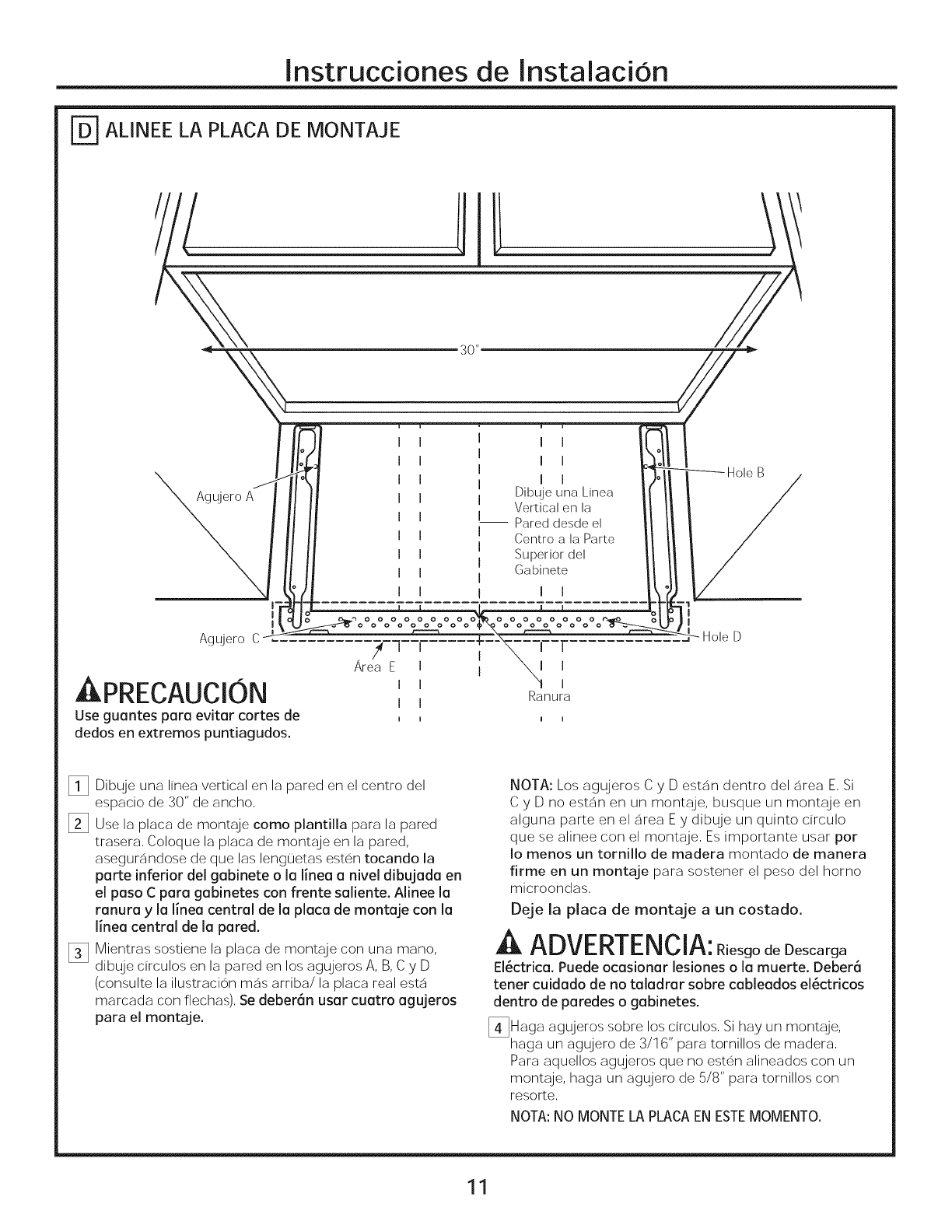
r-D-]ALINEE LA PLACA DE MONTAJE
Agujero C
,&PRECAUCION
Use guantes para evitarcortesde
dedos en extremos puntiagudos.
i i
i i
i i
Dibuje una Linea
Vertical en la
-- Pared desde el
Centro a la Parte
Superior del
Gabinete
I I
Hole B
Hole D
_i_ Dibuje una linea vertical en la pared en el centro del
espacio de 30" de ancho,
[] Use la placa de montaje como plantilla para la pared
trasera, Coloque la placa de montaje en la pared,
asegurandose de que las lengL]etas esten tocando la
parte inferior del gabinete o la linea a nivel dibujada en
el paso C para gabinetes con frente saliente. Alinee la
ranura y la linea central de la placa de montaje con la
linea central de la pared.
_3 Mientras sostiene la placa de montaje con una mano,
dibuje circulos en la pared en los agujeros A, B, C y D
(consulte la ilustracion mas arriba/la placa real esta
marcada con flechas), Se deberan usar cuatro agujeros
para el montaje.
NOTA: Los agujeros C y D estan dentro del area E, Si
C y D no estan en un montaje, busque un montaje en
alguna parte en el area Ey dibuje un quinto drculo
que se alinee con el montaje, Es importante usar pot
Io menos un tornillo de madera montado de manera
firme en un montaje para sostener el peso del homo
microondas,
Deje la placa de montaje a un costado.
ADVERTENCIA:Riesgo deDescarga
El_ctrica. Puede ocasionar lesiones o la muerte. Deber6
tener cuidado de no taladrar sobre cableados el_ctricos
dentro de paredes o gabinetes.
[_Haga agujeros sobre los circulos, Si hay un montaje,
haga un agujero de 3/16" para tornillos de madera,
Para aquellos agujeros que no esten alineados con un
montaje, haga un agujero de 5/8" para tornillos con
resorte,
NOTA: NO MONTE LA PLACA EN ESTEMOMENTO.
11
Instrucciones de InstalaciOn
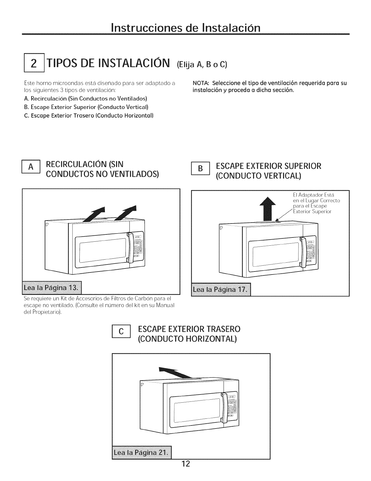
TIPOS DE INSTALACION
Este homo microondas esta diser]ado para set adaptado a
los siguientes 3 tipos de ventilacion;
A. Recirculacion (Sin Conductos no Ventilados)
B. Escape Exterior Superior (Conducto Vertical)
C. Escape Exterior Trasero (Conducto Horizontal)
(Elija A, B o C)
NOTA: Seleccione el tipo de ventilaci6n requerida para su
instalaci6n y proceda a dicha secci6n.
[_ RECIRCULACION (SIN
CONDUCTOS NO VENTILADOS) ESCAPEEXTERIORSUPERIOR
(CONDUCTO VERTICAL)
El Adaptador Est__i
en el Lugar Correcto
para el Escape
Exterior Superior
Se requiere un Kit de Accesorios de Filtros de Carbon para el
escape no ventilado, (Consulte el nLimero del kit en su Manual
del Propietario),
ESCAPEEXTERIORTRASERO
(CONDUCTO HORIZONTAL)
12
Instrucciones de Instalacion
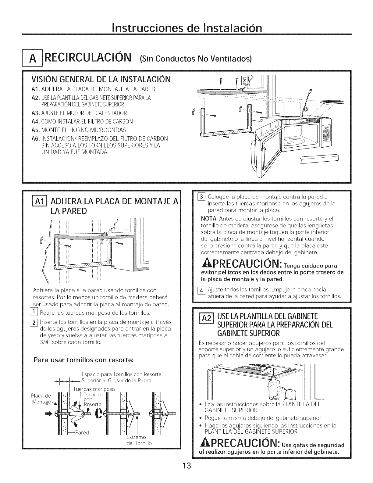
F- RECIRCULACION (si Cood ctosNoVentilados)
VISION GENERAL DE LA INSTALACION
A1. ADHERA LA PLACA DE MONTAJE A LA PARED
A2. USELA PLANTILLADELGABINETESUPERIORPARALA
PREPARACIONDELGABINETESUPERIOR
A3. AJUSTE EL MOTORDELCALENTADOR
A4. COMO INSTALARELFILTRODECARBON
A5. MONTE EL HORNO MICROONDAS
A6. INSTALACION/REEMPLAZO DEL FILTRO DECARBON
SIN ACCESOA LOS TORNILLOS SUPERIORESY LA
UNIDAD YA FUE MONTADA
f
ADHERA LA PLACA DE MONTAJE A
LA PARED
Adhiera la placa a la pared usando tornillos con
resortes, Pot Io menos un tornillo de madera debera
set usado para adherir la placa al montaje de pared,
[]Retire las tuercas mariposa de los tornillos,
[] Inserte los tornillos en la placa de montaje a traves
de los agujeros designados para entrar en la placa
de yeso y vuelva a ajustar las tuercas mariposa a
3/4" sobre cada tornillo,
Para usar tornillos con resorte:
Placa de
Espacio para Tornillos con Resorte
-_-_J_---- Superior al Grosor de la Pared
i Tuercas mariposa
Torni,oII I",'1
cOn;oi_ "_
_xtremo
del Tornillo
[] Coloque la placa de montaje contra la pared e
inserte las tuercas mariposa en los agujeros de la
pared para montar la placa,
NOTA: Antes de ajustar los tornillos con resorte y el
tornillo de madera, aseg0rese de que las lenguetas
sobre la placa de montaje toquen la parte inferior
del gabinete o la linea a nivel horizontal cuando
se Io presione contra la pared y que la placa este
correctamente centrada debajo del gabinete,
APRECAUCION: Teogac. dadopar°
evitar pellizcos en los dedos entre la parte trasera de
la placa de montage y la pared.
[_ Ajuste todos los tornillos, Empuje la placa hacia
afuera de la pared para ayudar a ajustar los tomillos,
| USELAPLANTILLADELGABINETE
SUPERIORPARALAPREPARACIONDEL
GABINETESUPERIOR
Es necesario hacer agujeros para los tornillos del
soporte superior y un agujero Io suficientemente grande
para que el cable de corriente Io pueda atravesar,
13
• Lea las instrucciones sobre la PLANTILLA DEL
GABINETE SUPERIOR,
• Pegue la misma debajo del gabinete superior,
• Haga los agujeros siguiendo las instrucciones en la
PLANTILLA DEL GABINETE SUPERIOR,
kPRECAUCION: Use gafas de seguridad
al realizar agujeros en la parte inferior del gabinete.
Instrucciones de InstalaciOn
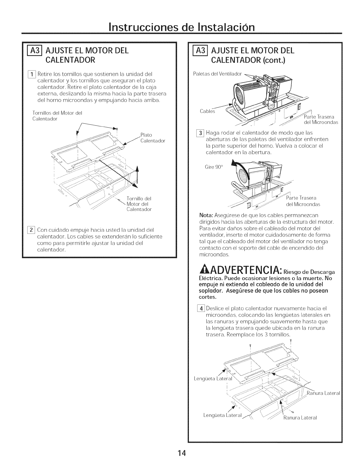
| AJUSTE EL MOTOR DEL
CALENTADOR
_!3 Retire los tornillos que sostienen la unidad del
calentador y los tornillos que aseguran el plato
calentador, Retire el plato calentador de la caja
externa, deslizando la misma hacia la parte trasera
del homo microondas y empujando hacia arriba,
Tornillos del Motor del
Calentador
Plato
Calentador
Tornillo del
"_ Motor del
Calentador
_3 Con cuidado empuje hacia usted la unidad del
calentador, Los cables se extenderan Io suficiente
como para permitirle ajustar la unidad del
calentador,
AJUSTE EL MOTOR DEL
CALENTADOR (cont.)
Paletas del Ventilador _.
Cabl i_ Trasera
........ _MicroSndas
_3 Haga rodar el calentador de modo que las
aberturas de las paletas del ventilador enfrenten
la parte superior del homo, Vuelva a colocar el
calentador en la abertura,
Gire 90°
oI-s _
rte Trasera
...._ _ _?-J_ c'elMicroondas
Nota: Asegurese de que los cables permanezcan
dirigidos hacia las aberturas de la estructura del motor,
Para evitar dar]os sobre el cableado del motor del
ventilador, inserte el motor cuidadosamente de forma
tal que el cableado del motor del ventilador no tenga
contacto con el soporte del cable de encendido del
microondas,
A_r_lrrnTr,lr, l_
LIL_UMIF r_/E II_l_li-I: Riesgo de Descarga
Electrica. Puede ocasionar lesiones o la muerte. No
empuje ni extienda el cableado de la unidad del
soplador. Aseg[irese de que los cables no posean
cortes.
[_3 Deslice el plato calentador nuevamente hacia el
microondas, colocando las lengL]etas laterales en
las ranuras y empujando suavemente basra que
la lengueta trasera quede ubicada en la ranura
trasera, Reemplace los 3 tornillos,
Lateral
Lengueta Lateral Ranura Lateral
14
Instrucciones de InstalaciOn
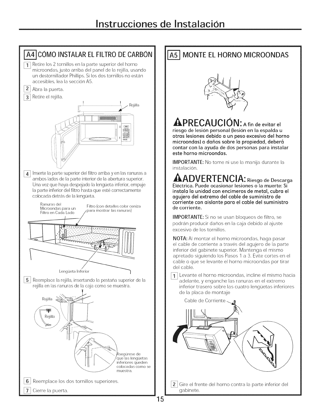
COMO INSTALAR EL FILTRO DE CARBON
_l] Retire los 2 tornillos on la pare superior del horno
microondas, justo arriba del panel de la rejilla, usando
un destornillador Phillips, Si los dos tornillos no estan
accesibles, lea la seccion AS,
_] Abra la puerta,
_] Retire el rejilla, !
[_ Inserte la pare superior del filtro arriba yen las ranuras a
ambos lades de la pare interior de la abertura superior,
Una vez que haya despejado la lengueta inferior, empuje
la pare inferior del filtro hasta que este correctamente
colocada detras de la lengueta,
Ranuras del Filtro (con detalles color ceniza
Microondas para un
Filtro en Cada Lade j para mostrar las ranuras)
[] Reemplace la rejilla, insertando la pestana superior de la
rejilla en las ranuras de la caja come se muestra,
Rejilla
hlrese de
que las lenguetas
inferiores queden
colocadas como se
muestra.
_] Reemplace los dos tornillos superiores,
[_ Cierre la puerta,
MONTE EL HORNO MICROONDAS
Annrr,
J:LrKr.._i-_U_| M|_: A fin de evitarel
riesgode lesionpersonal (lesi6nen la espalda u
otraslesionesdebido a un peso excesivo del homo
microondas} o da_os sobre la propiedad, debera
contar con laayuda de dos personas para instalar
este horno microondas.
IMPORTANTE: No tome ni use la manija durante la
instalacion,
AADVERTENClA: R esgodeDescarga
Electrica. Puede ocasionar lesiones o la muerte: Si
instala la unidad con encimeros de metal, cubra el
agujero del extreme del cable de suministro de
corriente con aislante para el cable del suministro
de corriente.
IMPORTANTE: Si no se usan bloqueos de filtro, se
podran producir dar%s en la caja debido al ajuste
excesivo de los tornillos,
NOTA: AI montar el homo microondas, haga pasar
el cable de corriente a traves del agujero de la parte
inferior del gabinete superior, Mantenga el mismo
apretado siguiendo los Pasos 1 a 3, Evite cortes en el
cable o que se levante el homo microondas per tirar
del cable,
_l] Levante el homo microondas, incline el mismo hacia
adelante, y enganche las ranuras en el extreme
inferior trasero sobre las cuatro lenguetas inferiores
de la placa de montaje
Cable de
15
Gire el frente del homo contra la parte inferior del
gabinete,

Instrucciones de InstalaciOn
| MONTE EL HORNO (cont.)
[] Inserte 3 tornillos autoalineantes (1/4" - 28 x 2 Y4")a
traves de los agujeros del gabinete superior externo,
De dos giros completos a cada tornillo,
Frente del Gabinete
Estante Inferior del Gabinete
Bloque de relleno
Esta distancia
Tquivalente a| NO puede
I la Profunidad| supe,rar
I del Hueco |las 2 para
del Gabinete $ _seguraruna
Y T ins[alaclor/
adecuada
Autoalineante
Parte Superior del Horno
Microondas
Tornillos Autoalineantes
[4_ Ajuste los tres tornillos en la parte superior
del homo microondas, (AI ajustar los tornillos,
sostenga el homo microondas en su posicion
contra la pared y el gabinete superior),
[_ Instale los filtros de grasa, Consulte el Manual del
Propietario embalado con el homo microondas,
_ INSTALAClON/REEMPLAZO DEL
FILTRODE CARBON SIN ACCESOA
LOSTORNILLOS SUPERIORESY LA
UNIDAD YA FUE MONTADA
DESMONTE EL HORNO MICROONDAS
_PRECAUCION: Ariodeevitarelriesgo
de lesion personal (lesion en la espalda u otras lesiones
debido a un peso excesivo del homo microondas) o
daffos sobre la propiedad, deber6 contar con la ayuda
de dos personas para instalar este homo microondas.
IMPORTANTE: No tome ni use la manija durante el retiro,
,ADVERTENClA: R esgodoDosoarga
Electrica. Puede ocasionar lesiones o la muerte: Si retira
la unidad con encimeros de metal, cubra el extremo del
agujero del cable del suministro de corriente con aislante
para el cable del suministro de corriente.
IMPORTANTE:Si no se usan bloqueos de filtro, se podr_n producir
danos en la caja debido al ajuste excesivo de lostornillos,
_i] Afloje los 3 tornillos en la parte superior del homo
microondas (dentro del gabinete),
[] Levante el homo microondas, incline el mismo hacia
adelante, y desenganche las ranuras en el extremo
inferior trasero sobre las cuatro lenguetas inferiores
de la placa de montaje,
16
[] Reemplace el filtro usando instrucciones de la
seccion A4,
[_ Vuelva a instalar la unidad siguiendo las
instrucciones de A5,
Instrucciones de Instalacion
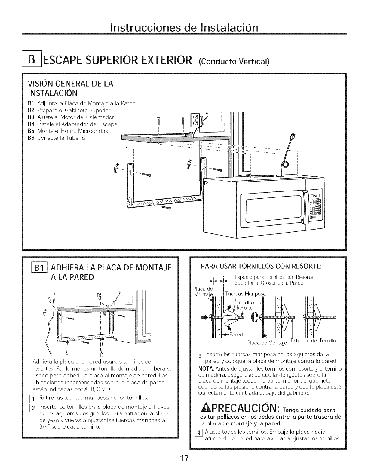
I-B-1ESCAPESUPERIOR EXTERIOR (CooductoVertical)
VISION GENERAL DE LA
INSTALACION
B1. Adjunte la Placa de Montaje a la Pared
B2. Prepare el Gabinete Superior
B3. Ajuste el Motor del Calentador
B4, Instale el Adaptador del Escape
B5. Monte el Homo Microondas
B6. Conecte la Tuberia
}
h
ADHIERA LA PLACA DE MONTAJE
A LA PARED
A
\
C' D
Adhiera la placa a la pared usando tornillos con
resortes, Por Io menos un tornillo de madera debera set
usado para adherir la placa al montaje de pared, Las
ubicaciones recomendadas sobre la placa de pared
estan indicadas por A, B, C y D,
_l] Retire las tuercas mariposa de los tornillos,
[] Inserte los tornillos en la placa de montaje a traves
de los agujeros designados para entrar en la placa
de yeso y vuelva a ajustar las tuercas mariposa a
3/4" sobre cada tornillo,
17
PARA USAR TORNILLOS CON RESORTE:
I Espacio para Tornillos con Resorte
i i bupertor at LJrosorde ta wared
Placa de i
Mo iTuercas Mariposa
'Torni,,oconll
Resorte ':.'
_p_r_d I1_ I!1 I
PlacadeMontaje ExtremodelTornillo
_] Inserte las tuercas mariposa en los agujeros de la
pared y coloque la placa de montaje contra la pared,
NOTA: Antes de ajustar los tornillos con resorte y el tornillo
de madera, asegurese de que las lenguetas sobre la
placa de montaje toquen la parte inferior del gabinete
cuando se las presione contra la pared y que la placa este
correctamente centrada debajo del gabinete,
,APRECAUCION: Tenga cuidado para
evitar pellizcos en los dedos entre la parte trasera de
ia piaca de montaje y ia pared.
_!_ Ajuste todos los tornillos, Empuje la placa hacia
afuera de la pared para ayudar a ajustar los tornillos,
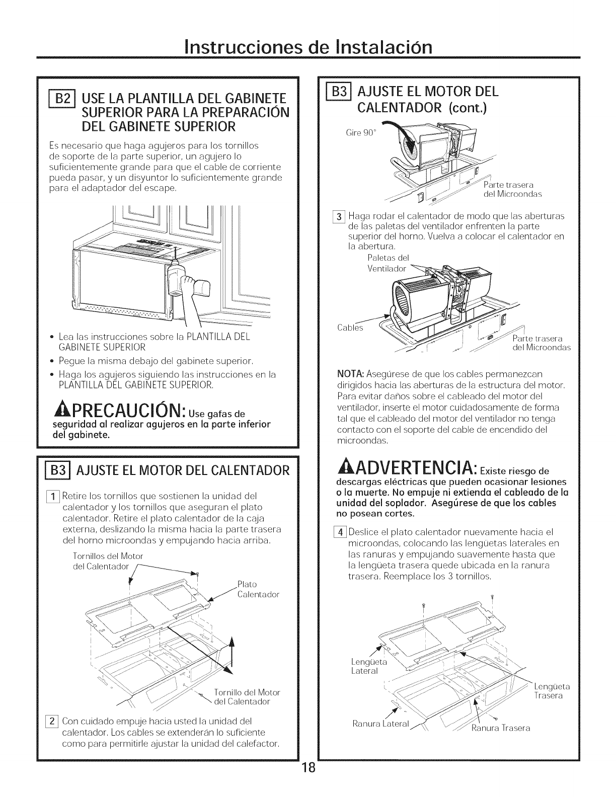
Instrucciones de InstalaciOn
USE LA PLANTILLA DEL GABINETE
SUPERIORPARA LA PREPARACION
DEL GABINETE SUPERIOR
Es necesario que haga agujeros para los tornillos
de soporte de la parte superior, un agujero Io
suficientemente grande para que el cable de corriente
pueda pasar, y un disyuntor Io suficientemente grande
para el adaptador del escape,
• Lea las instrucciones sobre la PLANTILLA DEL
GABINETE SUPERIOR
• Pegue la misma debajo del gabinete superior.
Haga los agujeros siguiendo las instrucciones en la
PLANTILLA DEL GABINETE SUPERIOR.
Annrr, AHr, l_
•-, Useg°fosde
seguridad al realizar agujeros en la parte inferior
del gabinete.
[_ AJUSTEELMOTOR DEL CALENTADOR
_!] Retire los tornillos que sostienen la unidad del
calentador y los tornillos que aseguran el plato
calentador. Retire el plato calentador de la caja
externa, deslizando la misma hacia la parte trasera
del homo microondas y empujando hacia arriba.
Tornillos del Motor
del Calentador_._
IPlato
Calentador
'-_ Tornillo del Motor
del Calentador
_] Con cuidado empuje hacia usted la unidad del
calentador. Los cables se extender_n Io suficiente
como para permitirle ajustar la unidad del calefactor.
| AJUSTE EL MOTOR DEL
CALENTADOR (cont.)
_¢_Js Parte trasera
._ J_ ..... del Microondas
_] Haga rodar el calentador de modo que las aberturas
de las paletas del ventilador enfrenten la parte
superior del homo. Vuelva a colocar el calentador en
la abertura.
Paletas del
Ventilador _
"___ P_r_etra_era
NOTA: Asegurese de que los cables permanezcan
dirigidos hacia las aberturas de la estructura del motor.
Para evitar da_os sobre el cableado del motor del
ventilador, inserte el motor cuidadosamente de forma
tal que el cableado del motor del ventilador no tenga
contacto con el soporte del cable de encendido del
microondas.
A ^r_mEnTE_lr'l_
AI-_/'%uvr K|IF II_lLwl_: Existe riesgo de
descargas electricas que pueden ocasionar lesiones
o la muerte. No empuje ni e_ienda el cableado de la
unidad del soplador. AsegLirese de que los cables
no posean cortes,
[_ Deslice el plato calentador nuevamente hacia el
microondas, colocando las lenguetas laterales en
las ranuras y empujando suavemente basra que
la lengueta trasera quede ubicada en la ranura
trasera. Reemplace los 3 tornillos.
I
Lengueta
Lateral
Ranura Lateral Ranura Trasera
Trasera
18
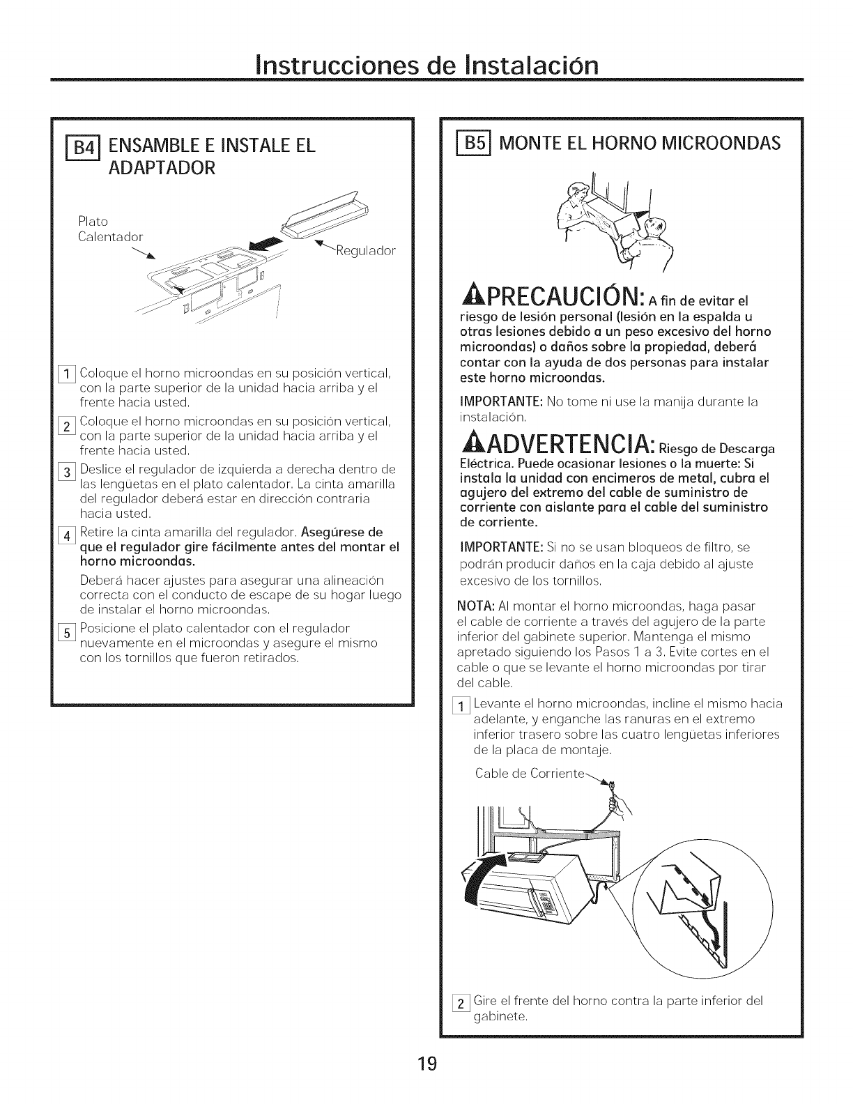
Instrucciones de InstalaciOn
rB-4] ENSAMBLE E INSTALE EL
ADAPTADOR
_l] Coloque el horno microondas en su posicion vertical,
con la parte superior de la unidad hacia arriba y el
frente hacia usted,
[] Coloque el homo microondas en su posicion vertical,
con la parte superior de la unidad hacia arriba y el
frente hacia usted,
_] Deslice el regulador de izquierda a derecha dentro de
las lenguetas en el plato calentador, La cinta amarilla
del regulador debera estar en direccion contraria
hacia usted,
[_ Retire la cinta amarilla del regulador, Asegorese de
que el regulador gire facilmente antes del montar el
homo microondas.
Debera hacer ajustes para asegurar una alineacion
correcta con el conducto de escape de su hogar luego
de instalar el horno microondas,
_] Posicione el plato calentador con el regulador
nuevamente en el microondas y asegure el mismo
con los tornillos que fueron retirados,
MONTE EL HORNO MICROONDAS
JirKr..%i-_u%|u|_: A fin de evitarel
riesgode lesionpersonal (lesionen la espalda u
otraslesionesdebido a un peso excesivo del homo
microondas) o da_os sobre la propiedad, deber6
contar con laayuda de dos personas para instalar
este horno microondas.
IMPORTANTE: No tome ni use la manUa durante la
instalacion,
r lmEnTE lr, l^
JII-I_UVlT l_|ILr" |_IIL_|_'_: Riesgo de Descarga
Electrica. Puede ocasionar lesiones o la muerte: Si
instala la unidad con encimeros de metal, cubra el
agujero del e×tremo del cable de suministro de
corriente con aislante para el cable del suministro
de corriente.
IMPORTANTE: Si no se usan bloqueos de filtro, se
podran producir da_os en la caja debido al ajuste
excesivo de los tornillos,
NOTA: AI montar el horno microondas, haga pasar
el cable de corriente a traves del agujero de la parte
inferior del gabinete superior, Mantenga el mismo
apretado siguiendo los Pasos 1 a 3, Evite cortes en el
cable o que se levante el homo microondas pot tirar
del cable,
_l] Levante el homo microondas, incline el mismo hacia
adelante, y enganche las ranuras en el extremo
inferior trasero sobre las cuatro lenguetas inferiores
de la placa de montaje,
Cable de
Gire el frente del homo contra la parte inferior del
gabinete,
19
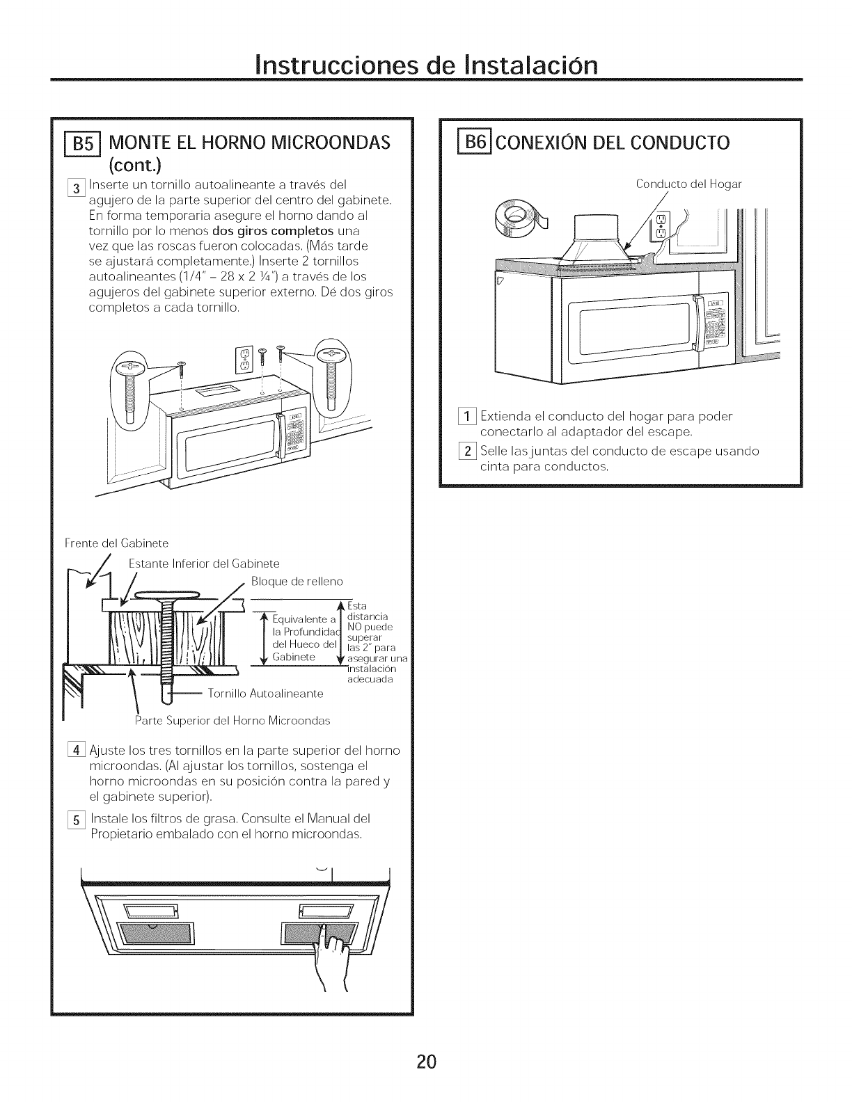
Instrucciones de Instalacion
F_ MONTE EL HORNO MICROONDAS
(cont.)
[] Inserte un tornillo autoalineante a traves del
agujero de la parte superior del centro del gabinete,
En forma temporaria asegure el homo dando al
tornillo por Io menos dos giros completos una
vez que las roscas fueron colocadas, (Mas tarde
se ajustara completamente,) Inserte 2 tornillos
autoalineantes (1/4" - 28 x 2 1/4")a traves de los
agujeros del gabinete superior externo, De dos giros
completos a cada tornillo,
Frente del Gabinete
Estante Inferior del Gabinete
Bloque de relleno
Esta
TEquivalente a/distancia
I la ProfundidaJ NO puede
_superar
del Hueco del _.,-o,, _._._.
_asegurar una
mstalacion
adecuada
-- Tornillo Autoalineante
Parte Superior del Horno Microondas
[] Ajuste los tres tornillos en la parte superior del homo
microondas, (AI ajustar los tornillos, sostenga el
homo microondas en su posicion contra la pared y
el gabinete superior),
[] Instale los filtros de grasa, Consulte el Manual del
Propietario embalado con el homo microondas,
CONEXlON DEL CONDUCTO
Conducto del Hogar
_!] Extienda el conducto del hogar para poder
conectarlo al adaptador del escape,
_] Selle lasjuntas del conducto de escape usando
cinta para conductos,
2O
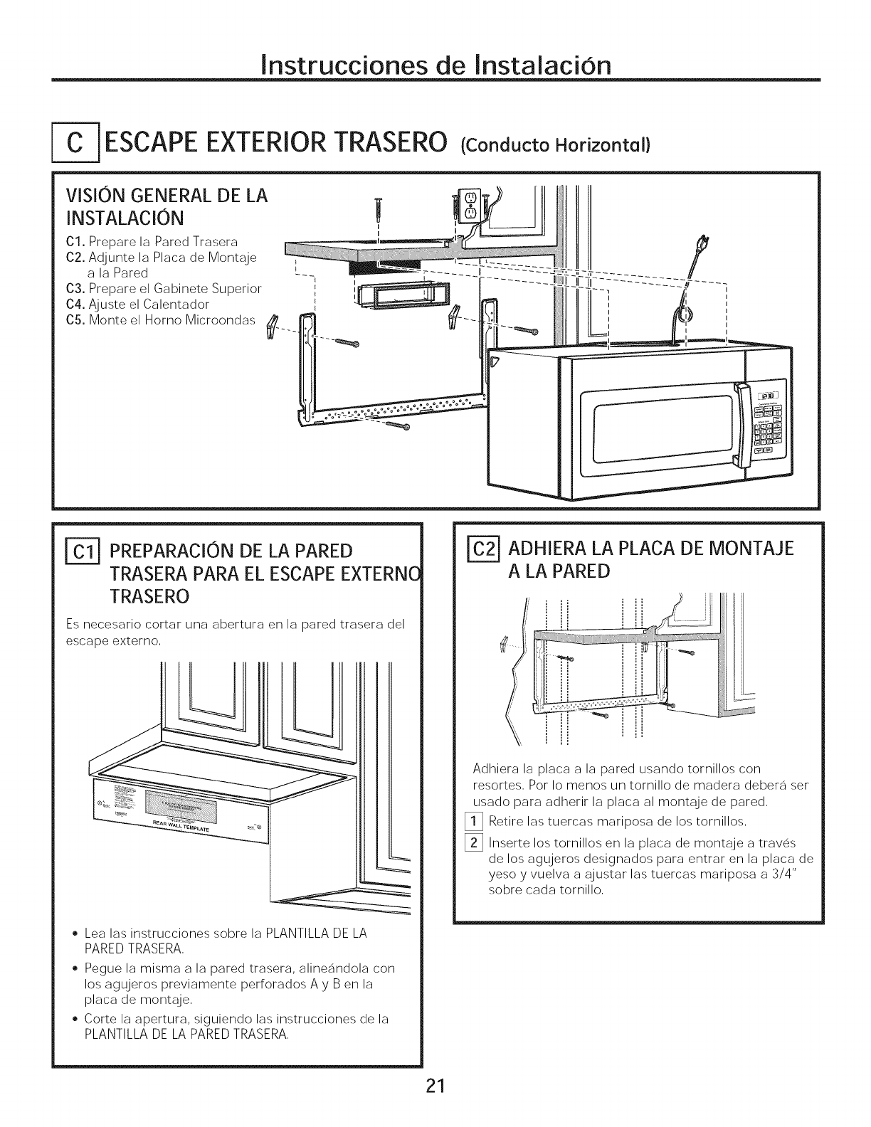
Instrucciones de Instalacion
-]ESCAPE EXTERIORTRASERO (ConductoHorizontal}
VISION GENERAL DE LA
INSTALACION
01, Prepare la Pared Trasera
62. Adjunte la Placa de Montaje _
a la Pared ---
03. Prepare el Gabinete Superior
04. Ajuste el Calentador _
05. Monte el Homo Microondas /#
I
I
I_] PREPARAClON DE LA PARED
TRASERA PARA EL ESCAPE EXTERN(
TRASERO
Es necesario cortar una abertura en la pared trasera del
escape externo.
• Lea las instrucciones sobre la PLANTILLA DE LA
PARED TRASERA.
• Pegue la misma a la pared trasera, alineandola con
los agu]eros previamente perforados A y Ben la
placa de montaje.
• Corte la apertura, siguiendo las instrucciones de la
PLANTILLA DE LA PARED TRASERA.
[_ ADHIERA LA PLACA DE MONTAJE
A LA PARED
i ...........-_ iiiIii
Adhiera la placa a la pared usando tornillos con
resortes. Por Io menos un tornillo de madera debera ser
usado para adherir la placa al montaje de pared,
[] Retire las tuercas mariposa de los tornillos,
[] Inserte los tornillos en la placa de montaje a traves
de los agujeros designados para entrar en la placa de
yeso y vuelva a ajustar las tuercas mariposa a 3/4"
sobre cada tornillo,
21
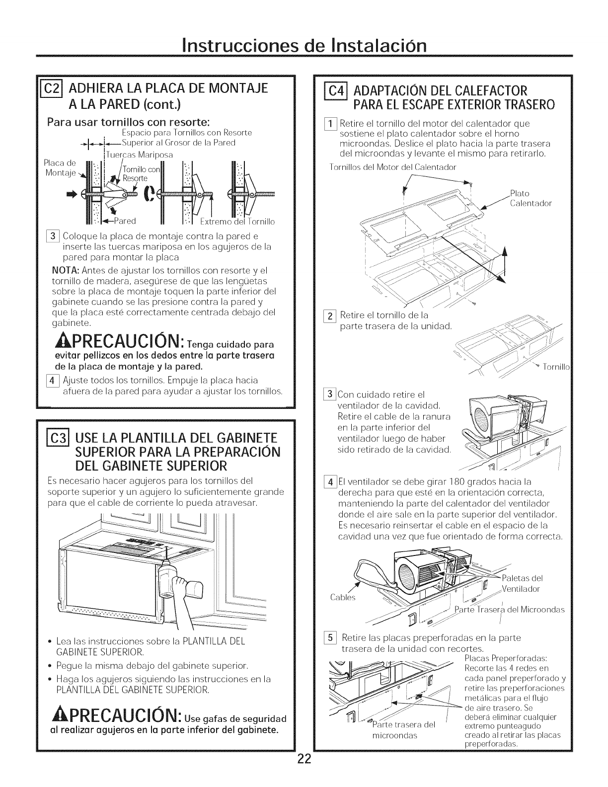
Instrucciones de InstalaciOn
ADHIERA LA PLACA DE MONTAJE
A LA PARED (cont,)
Para usar tornillos con resorte:
Espacio para Tornillos con Resorte
-_l_-_J_----Superior al Grosor de la Pared
Ii
iTuercas Marlposa
Placa de
Extremo del Tornillo
[] Coloque la placa de montaje contra la pared e
inserte las tuercas mariposa en los agujeros de la
pared para montar la placa
NOTA: Antes de ajustar los tornillos con resorte y el
tornillo de madera, asegorese de que las lenguetas
sobre la placa de montaje toquen la parte inferior del
gabinete cuando se las presione contra la pared y
que la placa este correctamente centrada debajo del
gabinete,
PRECAUCION: Tenga cuidado para
evitar pellizcos en los dedos entre la parte trasera
de la placa de montaje y la pared.
[_ Ajuste todos los tornillos, Empuje la placa hacia
afuera de la pared para ayudar a ajustar los tornillos,
r_ USE LA PLANTILLA DEL GABINETE
SUPERIOR PARA LA PREPARACION
DEL GABINETE SUPERIOR
Es necesario hacer agujeros para los tornillos del
soporte superior y un agujero Io suficientemente grande
para que el cable de corriente Io pueda atravesar,
• Lea las instrucciones sobre la PLANTILLA DEL
GABINETE SUPERIOR,
• Pegue la misma debajo del gabinete superior,
Haga los agujeros siguiendo las instrucciones en la
PLANTILLA DEL GABINETE SUPERIOR,
APRECAUCION: Usegafasdeseguridad
al realizar agujeros en la parte inferior del gabinete.
22
ADAPTACIONDELCALEFACTOR
PARAELESCAPEEXTERIORTRASERO
_] Retire el tornillo del motor del calentador que
sostiene el plato calentador sobre el homo
microondas, Deslice el plato hacia la parte trasera
del microondas y levante el mismo para retirarlo,
Tornillos del Motor del Calentador
; Plato
Calentador
_] Retire el tornillo de la
parte trasera de la unidad,
_ Tornillc
_]Con cuidado retire el
ventilador de la cavidad,
Retire el cable de la ranura
en la parte inferior del
ventilador luego de haber
sido retirado de la cavidad,
[_EI ventilador se debe girar 180 grados hacia la
derecha para que este en la orientacion correcta,
manteniendo la parte del calentador del ventilador
donde el aire sale en la parte superior del ventilador,
Es necesario reinsertar el cable en el espacio de la
cavidad una vez que fue orientado de forma correcta,
Cables
Ventilador
/
Parte Trasera del Microondas
_] Retire las placas preperforadas en la parte
trasera de la unidad con recortes,
Placas Preperforadas:
_,-_1__ Recorre las 4 redes en
,0_[_'- __'_;_o _ cada panel preperforado y
___i retire las preper foraciones
meta,ioasparae, ,.jo
J_ ' __--_ de aire trasero, Se
1_!._._"_ _ /debera eliminar cualquier
rarte trasera del extremo punteagudo
microondas creado al retirar las placas
preperforadas,
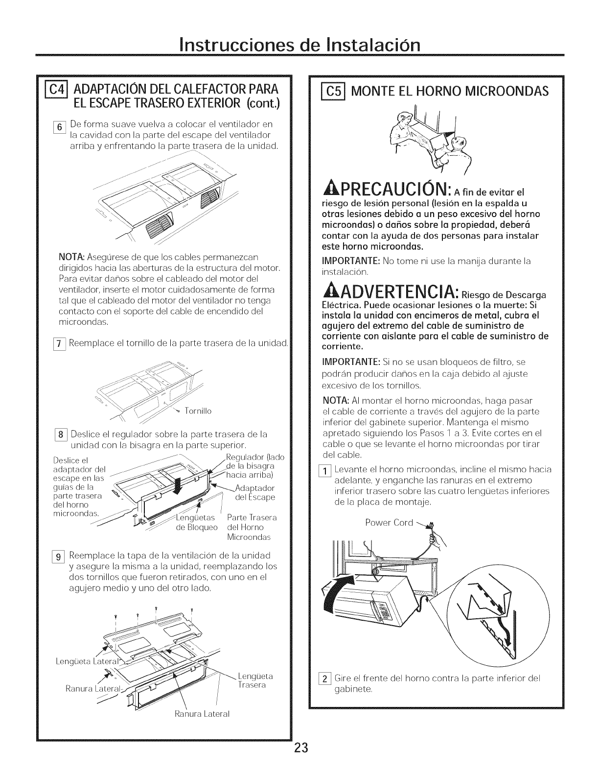
Instrucciones de InstalaciOn
ADAPTACIONDELCALEFACTORPARA
ELESCAPETRASEROEXTERIOR(cont.)
_] De forma suave vuelva a colocar el ventilador en
la cavidad con la parte del escape del ventilador
arriba y enfrentando la parte trasera de la unidad,
s.. --fj /
NOTA: Asegurese de que los cables permanezcan
dirigidos hacia las aberturas de la estructura del motor,
Para evitar da_os sobre el cableado del motor del
ventilador, inserte el motor cuidadosamente de forma
tal que el cableado del motor del ventilador no tenga
contacto con el soporte del cable de encendido del
microondas,
[_ Reemplace el tornillo de la parte trasera de la unidad,
"-_ Tornillo
[] Deslice el regulador sobre la parte trasera de la
unidad con la bisagra en la parte superior,
Deslice el _ _ (lado
adaptador del _ de la bisagra
escape en las arriba)
guias de la
parte trasera del Escape
del homo
microondas, uetas Parte Trasera
deBIoqueo delHorno
Microondas
_] Reemplace la tapa de la ventilacion de la unidad
y asegure la misma a la unidad, reemplazando los
dos tornillos que fueron retirados, con uno en el
agujero medio y uno del otto lado,
Lengueta Lateral
Ranura Lateral
Ranura Lateral
Trasera
r_ MONTE EL HORNO MICROONDAS
APRECAUCION: Ariodeevitarel
riesgode lesionpersonal (lesionen laespalda u
otras lesionesdebido a un peso excesivo del homo
microondas) o da_os sobre la propiedad, deber6
contar con la ayuda de dos personas para instahr
este horno microondas.
IMPORTANTE: No tome ni use la manija durante la
instalacion,
AADVERTENClA: R esgodeDescarga
Electrica. Puede ocasionar lesiones o la muerte: Si
instala la unidad con encimeros de metal, cubra el
agujero del extremo del cable de suministro de
corriente con aislante para el cable de suministro de
corriente,
IMPORTANTE: Si no se usan bloqueos de filtro, se
podran producir da_os en la caja debido al ajuste
excesivo de los tornillos,
NOTA: AI montar el horno microondas, haga pasar
el cable de corriente a traves del agujero de la parte
inferior del gabinete superior, Mantenga el mismo
apretado siguiendo los Pasos 1 a 3, Evite cortes en el
cable o que se levante el homo microondas pot tirar
del cable,
_i] Levante el homo microondas, incline el mismo hacia
adelante, y enganche las ranuras en el extremo
inferior trasero sobre las cuatro lenguetas inferiores
de la placa de montaje,
Power Cord
Gire el frente del homo contra la parte inferior del
gabinete,
23
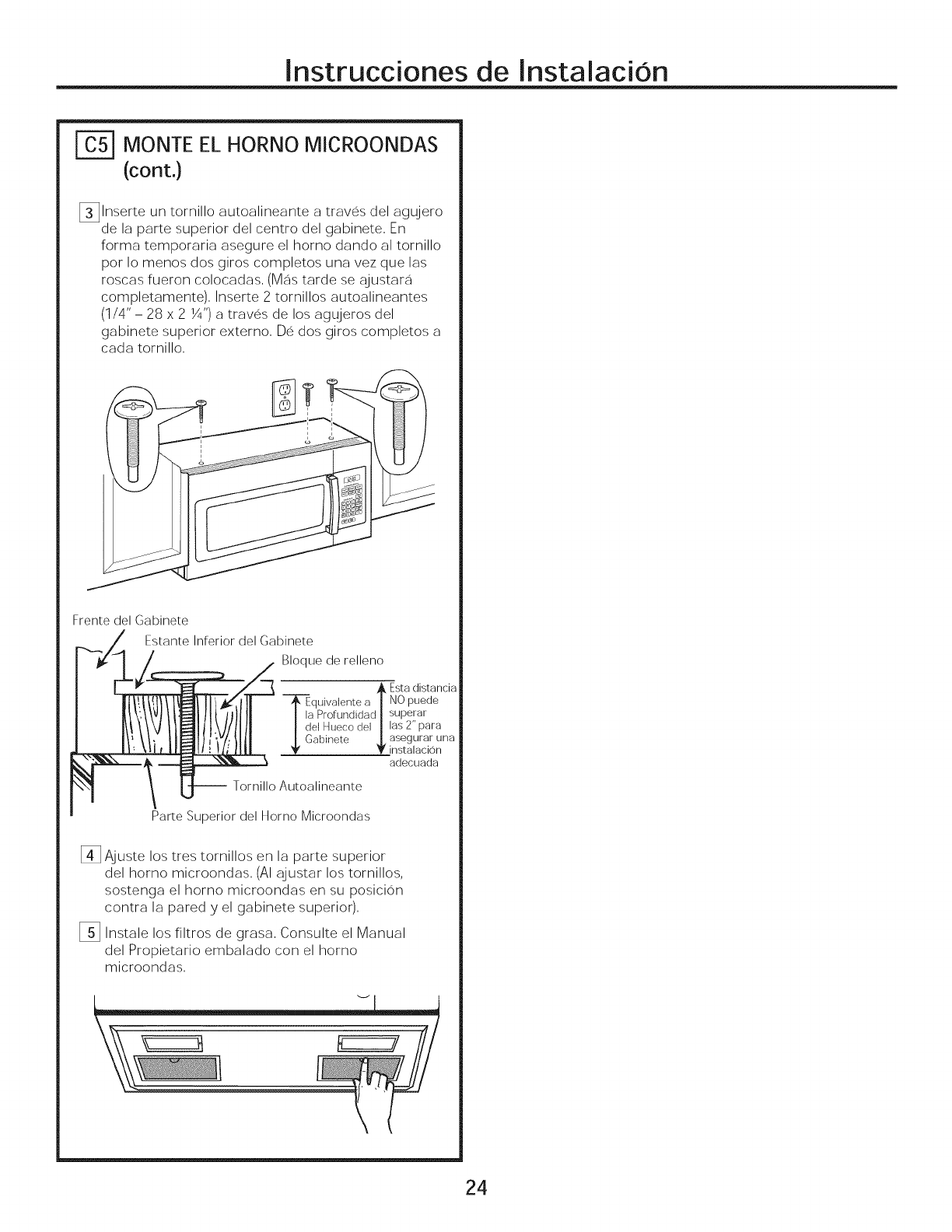
Instrucciones de Instalacion
| MONTE EL HORNOMICROONDAS
(cont.)
[]lnserte un tornillo autoalineante a traves del agujero
de la parte superior del centro del gabinete, En
forma temporaria asegure el homo dando al tornillo
pot Io menos dos giros completos una vez que las
roscas fueron colocadas, (Mas tarde se ajustara
completamente), Inserte 2 tornillos autoalineantes
(1/4"- 28 x 2 Y4")a traves de los agujeros del
gabinete superior externo, De dos giros completos a
cada tornillo,
Frente del Gabinete
Estante Inferior del Gabinete
Bloque de relleno
_. Esta distancia
Tquivalente a _ NO puede
] la Profundidad|superar
I del Hueco del |las 2" para
Oabinete _|. asegurar una
instalacion
adecuada
-- Tornillo Autoalineante
Parte Superior del Horno Microondas
[] Ajuste los tres tornillos en la parte superior
del homo microondas, (AI ajustar los tornillos,
sostenga el homo microondas en su posicion
contra la pared y el gabinete superior),
_] Instale los filtros de grasa, Consulte el Manual
del Propietario embalado con el homo
microondas,
24
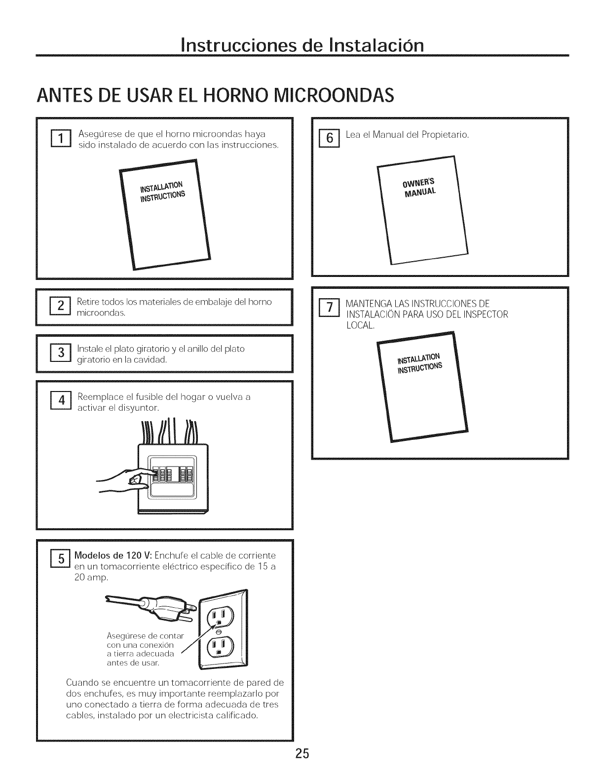
Instrucciones de InstalaciOn
ANTES DE USAR EL HORNO MICROONDAS
FT1
Asegurese de que el homo microondas haya
sido instalado de acuerdo con las instrucciones, r_ Lea el Manual del Propietario,
r 1
giratorio en la cavidad,
Reemplace el fusible del hogar o vuelva a
activar el disyuntor,
r_ ANTENGALASINSTRUCCIONESDE
INSTALACIONPARAUSODELINSPECTOR
LOCAL,
r_ Modelos de 120 V: Enchufe el cable de corriente
en un tomacorriente electrico especifico de 15 a
20 amp,
Asegurese de contar
con una conexion
a qerra adecuada
anLes de usar,
Cuando se encuentre un tomacorriente de pared de
dos enchufes, es muy importante reemplazarlo por
uno conectado a tierra de forma adecuada de tres
cables, instalado pot un electricista calificado,
25

Instrucciones de InstalaciOn
26
Impreso en China
