GE AZ75E09DACM1 User Manual ZONELINE Manuals And Guides L0604543
GE Package Units(both units combined) Manual L0604543 GE Package Units(both units combined) Owner's Manual, GE Package Units(both units combined) installation guides
User Manual: GE AZ75E09DACM1 AZ75E09DACM1 GE ZONELINE - Manuals and Guides View the owners manual for your GE ZONELINE #AZ75E09DACM1. Home:Heating & Cooling Parts:GE Parts:GE ZONELINE Manual
Open the PDF directly: View PDF ![]() .
.
Page Count: 28
ge.com
©
©
Safety Instructions ........... 2
Operati_ Instructions
Controls--Dip Switches ...... 3-5
Controls--Terrain al
Connections .............. 6, 7
On/Off Switch ............... 8
Ventilation Control ........... 8
Care and Cleaning
Air Filters ................... 9
Base Pan ................... 9
Exhaust Coils ................ 9
Installation Instruc_tions
Electrical Supply' ......... ] 1-13
Installing the Zoneline .... ] 4-21
Preparation ................ ] 0
Servicing .................. 22
Troubleshooting Tips ....... 23
Normal Operating Sounds .... 24
Consumer Support
Consumer Support . . .Back Cover
Product Registration ...... 25, 26
*¢\arranty .................. 27
Write the model and serial
numbers here:
Model #
Serial #
Find these numbers on a label
on tile fl'ont case panel.
Heat/Cool and
Heat Pu_@ Modds
7500 Series
TINSEA469JBRZ 49-7534 12-05JR
IMPORTANTSAFETYINFORMATION.
READALLINSTRUCTIONSBEFOREUSING.
WARNING!
For your safe_ the information in this manual must be followed to minimize the risk of fire, electric
shock, or to prevent property damage, personal injury, or loss of life.
_\ "_____SAFETYPRECAUTIONS
_y_ • This Zoneline must be properly
installed ira accordance with tile
Installauon Instrucuons before it is
used. See the Installation Instructions
ira tile back of this manual.
Replace immediately all electric service
cords that have become frayed or
otherwise damaged. A damaged power
supply cord must be replaced with a
new power supply cord obtained from
the mamffacturer and not repaired.
Do not use a cord that shows cracks or
abrasion damage along its length or at
either tile plug or connector erad.
•Unplug or disconnect tile Zoneline at
tile fllse box or circuit breaker before
making any repairs.
NOTE."VVestrongly recommend that any
servicing be performed by a qualified
individual.
•All air conditioners contain refligerants,
which under federal law must be
removed prior to product disposal. If
you are getting rid of an old product
with refrigerants, check with the
company handling disposal about wh at
to do.
READANDFOLLOWTHISSAFETYINFORMAtiONCAREFULLY.
SAVETHESEINSTRUCTIONS
2
Controls-dipswitches. .ecorn
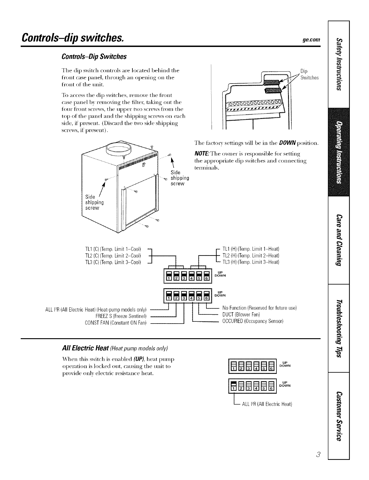
Controls-Dip Switches
The dip sxfitch controls are located behind the
front case I)anel, through, an opening on the
front of the unit.
To access the dip sMtches, remove the front
case panel by removing the filtex, taking out the
ti)ur fl'ont screws, the upper two screws fl'om the
top of the panel and the shipping screws on each
side, if present. (Discard the two side shipping
screws, if present).
zDip
7Switches
Side
• _, shipping
screw
The fi_cto Usettings will be in the DOWN position.
NOTE:The owner is responsible tot setting
the appropriate dip switches and connecting
temdnals.
TL1(C)(Temp.Limit1-Cool)
TL2(C)(Temp.Limit2-Cool)
TL3(C)(Temp.Limit3-Cool)
ALLI_R(All ElectricHeat)(Heat-pumpmodelsonly) --
FREEZS (FreezeSentinel)
CONSTFAN(ConstantONFan)
TL1(H)(Temp.Limit1-Heat)
TL2(H)(Temp.Limit2-Heat)
TL3(H)(Temp.Limit3-Heat)
[__ u_
DOWN
'Ill, No_.
All Electric Heat (Heat pump models only)
When this switch is enabled (UP), heat pump
operation is locked out, causing the unit to
provide only electric resistance heat. [BE]E]BBB]°_
DOWN
[ BBBBB]°"
DOWN
L ALLI_R(All ElectricHeat)
3
Controls-dipswitches.
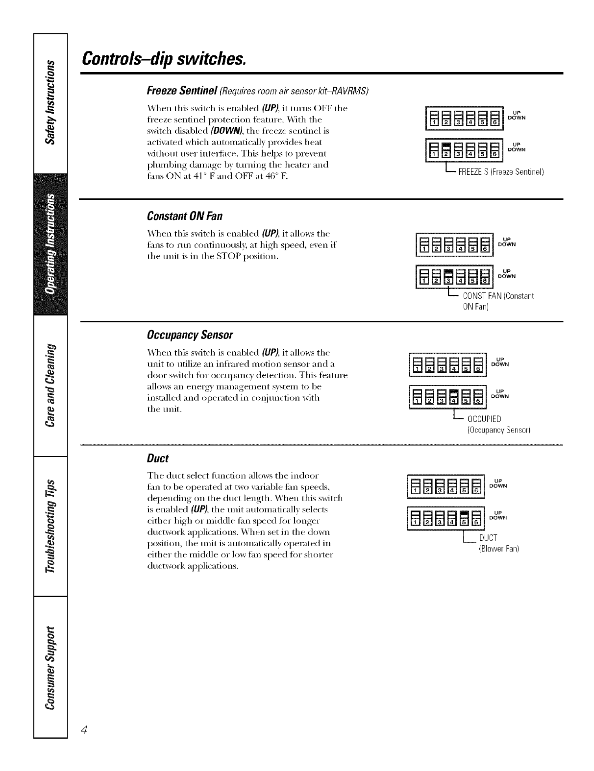
Freeze Sentinel (Requires room air sensor kit-RA VRMS)
_,_]mn this switch is enabled (UP), it turns OFF tile
ti'eeze sentinel protection feature. _._]th tile
switch disabled (DOWN), the freeze sentinel is
acfi\_ted which automatically provides heat
without user intedi_ce. This helps to prevent
I)lumbing damage by turning tile heater and
rims ON at 41 ° F and OFF at 46 ° E
]BBBBBB]°"
DOWN
[B BBBB]
DOWN
L_ FREEZES (FreezeSentinel)
ConstantON Fan
X4qmn this switch is enabled (UP),it allows tile
rims to rtm continuously at high speed, exert if
tile trait is in tile STOP position. [[ BBBBB]D,
DOWN
DOWN
L CONSTFAN(Constant
ONFan)
OccupancySensor
_,_]/en this switch is enabled (UP), it allows tile
trait to utilize an infl'ared motion sensor and a
door switch tot occui)ancy detection. This timtm'e
allows an energy' management system to be
installed and operated in conjtmction with
tile tmit.
laaaaaal°"
DOWN
lBBB J°"
DOWN
L OCCUPIED
(OccupancySensor)
Duct
Tile duct select flmcfion allows tile indoor
tim to be operated at two wn_iable tim speeds,
depending on the duct length. X,\]mn this switch
is enabled (UP), the unit automaficallv selects
either high or middle tim speed for longer
ductwork applications. When set in the down
position, the trait is automatically operated in
either the middle or low tim speed ti)r shorter
ductwork applications.
[BBBBBB[
DOWN
[BBBBBB[
DOWN
LDUCT
(BlowerFan)
4
ge.com
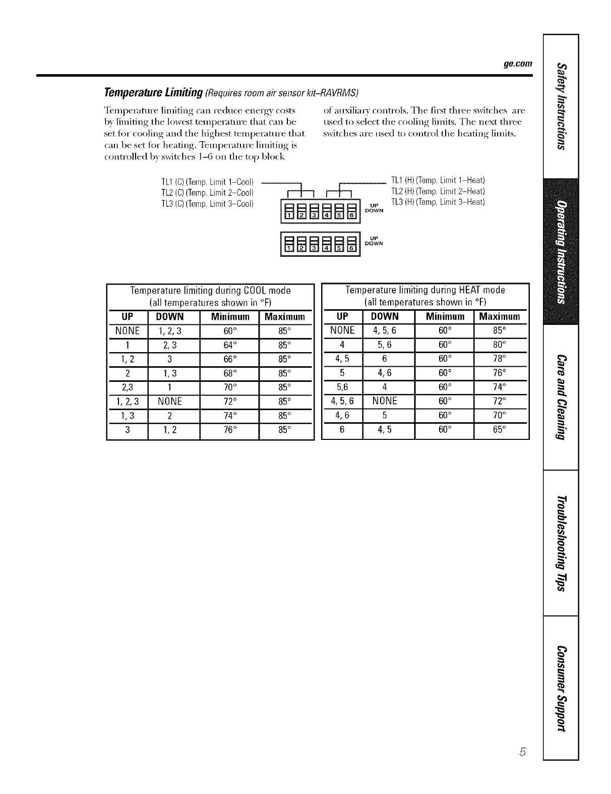
Temperature Limiting(Requiresroom air sensorkit-RAVRMS)
Temperature limiting can reduce energy costs of auxiliary controls. The ti_t three switches are
b)' limiting the lowest teini)erature that can be used to select the cooling limits. The next three
set fin" cooling and the highest temperature that switches are used to control the heating limits.
can be set fin" heating, TemI)erature limiting is
controlled by switches 1-6 on the top block
TL1(C)(Temp.Limit1-Cool)
TL2(C)(Temp.Limit2-Cool)
TL3(C)(Temp.Limit3-Cool) [aBBBBBI
DOWN
[aaaaaal
DOWN
TL1(H)(Temp.Limit 1-Heat)
TL2(H)(Temp.Limit2-Heat)
TL3(H)(Temp.Limit3-Heat)
Temperature limiting during COOLmode
(all temperatures shown in °F)
UP DOWN Minimum Maximum
NONE 1, 2, 3 60° 85°
1 2,3 64° 85°
1, 2 3 66° 85°
2 1,3 68° 85°
2,3 1 70° 85°
1, 2, 3 NONE 72° 85°
1,3 2 74° 85°
3 1, 2 76° 85°
Temperature limiting during HEATmode
(all temperatures shown in °F)
UP DOWN Minimum Maximum
NONE 4, 5, 6 60° 85°
4 5, 6 60° 80°
4, 5 6 60° 78°
5 4, 6 60° 76°
5,6 4 60° 74°
4, 5, 6 NONE 60° 72°
4, 6 5 60° 70°
6 4, 5 60° 65°
5
Controlsmterminalconnections.
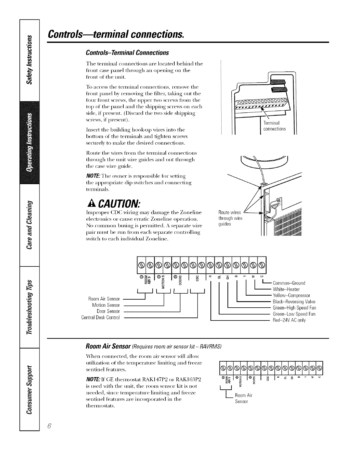
Controls-TerminalConnections
Tile texminal connections are located behind tile
front case panel through, an oi)ening, on tile
fl'ont of tile unit.
To access tile teFmillal COllllectiollS, remove tile
fl'ont panel by removing tile filtei, taking out tile
fimr fl'ont screws, tile upper two screws from tile
top ot the panel and the shipping screws on each
side, if present. (Discard the two side shipping
screws, if present).
Insert tile building hook-up wires into tile
bottom ol tile terminals and tighten screws
securely to make tile desired connections.
Route tile wires fl'om tile temfinal connections
through tile unit wire guides and out through
the case wire guide.
NO_.; The owner is responsible tot setting
tile appropriate dip switches and connecting
temfinals.
CAUTION:
hnproper CDC Mring may damage tile Zoneline Routewires
electronics or cause erratic Zoneline operation, through wire
No common busing is permitted. A separate wire guides
pair must be run fl'om each separate controlling
switch to each individual Zoneline,
l H®l®l®i®l®i®l®l®l®l®l
RoomAir Sensor
MotionSensor
DoorSensor
CentralDeskControl
o o [_ ommon-Ground
White-Heater
Yellow-Compressor
Black-Reversing Valve
Green-High Speed Fan
Green-Low Speed Fan
Red-24V AC only
Room Air Sensor (Requiresroom air sensorkit- RAVRMS)
"_._q/en connected, tile r(iom air sensor will alh)w
utilization of tile teinperature limiting and freeze
sentinel fb'atures.
NOTE: If GE them_ostat ]LM(147P2 or ILM(163P2
is used with tile unit, tile room sensor kit is not
needed, since temperature limiting and freeze
sentinel features are incoq)orated in tile
them_ostats.
o_ _o
_:'* S= o
L Room Air
Sensor
ge.com
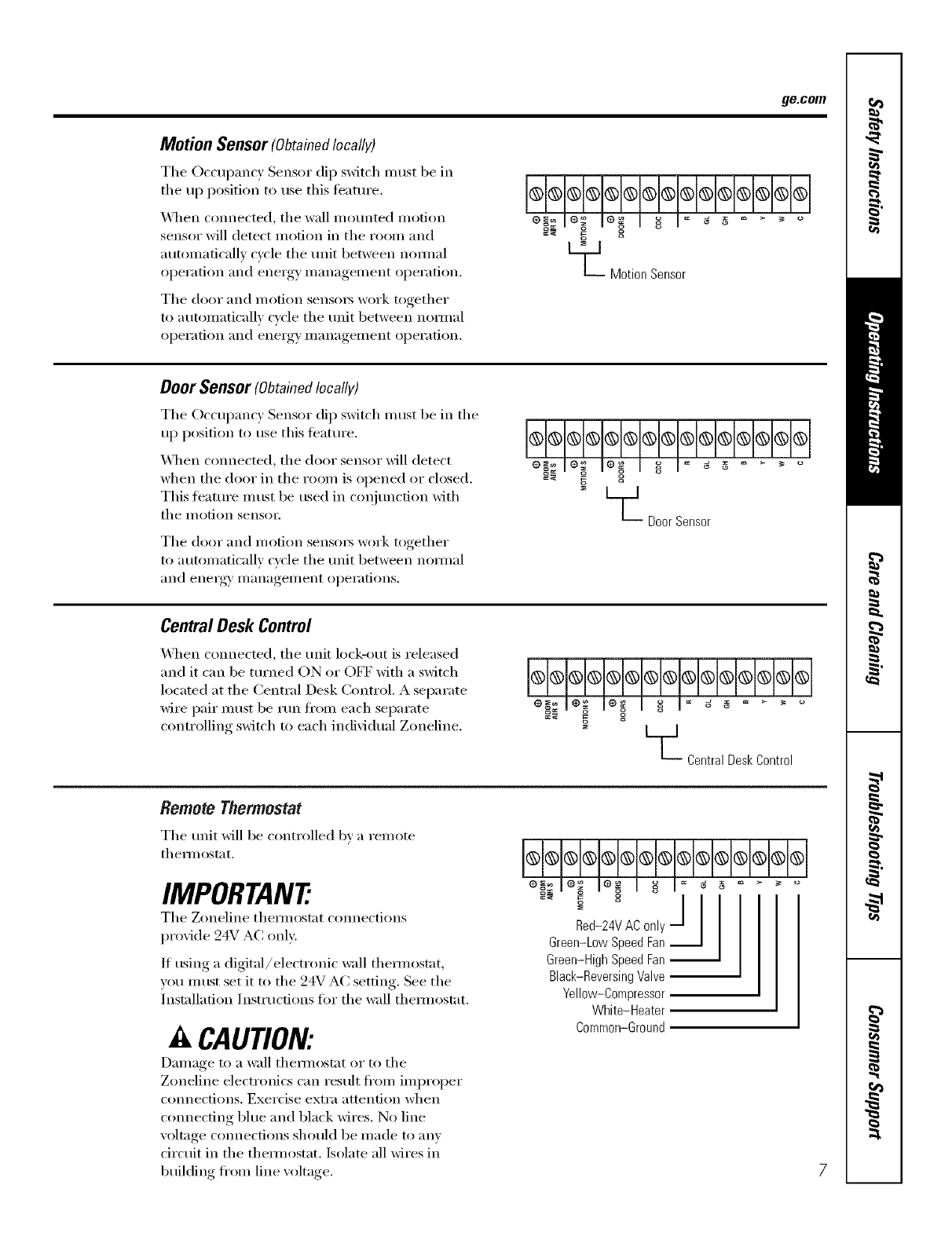
Motion Sensor (Obtainedlocally)
Tile Occupancy Sensor dip switch nmst be ill
tile up position to use this teature.
\_]/en connected, the wall mounted motion
sensor will demct motion in the room and
autolnaficallv cycle tile unit between nomml
operation and energy inanagelnent operation.
Tile door and Inofion sensoI_ work together
to automatically cycle the unit between nomml
operation and energy inanagelnent operation.
I I o o
L_ Motion Sensor
Door Sensor (Obtainedlocally)
The Occupancy Sensor dip switch must be in the
up position to use this teatuI'e.
_]/en connected, tile door sensor will detect
when tile door ill tile room is opened or closed.
This ti_atuI'e n/ust be used in coqjunction with
tile i/lotion sensoI:
The door and i/lotion sensoi3 work together
to auton/aticallv cycle the unit between mmnal
and enei'_ry,, i//anagei//ent, ol)ei'ations.
CentralDesk Control
\4lien connected, tile unit lock-out is released
and it can be turned ON or OFF with a switch
located at the (:entral Desk (;ontrol. A separate
wire pair must be run fl'om each separate
controlling switch to each individual Zoneline.
Remote Thermostat
The unit will be controlled by a rein ote
themlostat.
IMPORTAN7
Tile Zoneline themlostat cmmections
provide 24V AC only.
If using a digiml/elecmmic wall themlostat,
you inust set it to tile 24V AC setting. See tile
Installation Instructions tor tile wall themlostat.
ACAUTION:
Dalnage to a wall themlostat or to tile
Zoneline electronics can result fl'Oln ilnproper
connections. Exercise extra attention when
connecting blue and black wires. No line
voltage connections should be inade to anv
drcuit ill tile d/elmostat. Isolate all wires ill
building fl'oln lille voltage.
Central Desk Control
cc_ -
Red-24V AC0nly
Green-LowSpeedFan
Green-HighSpeedFan
Black-ReversingValve
Yellow-Compressor
White-Heater
Common-Ground
Otherfeaturesof yourZoneline.
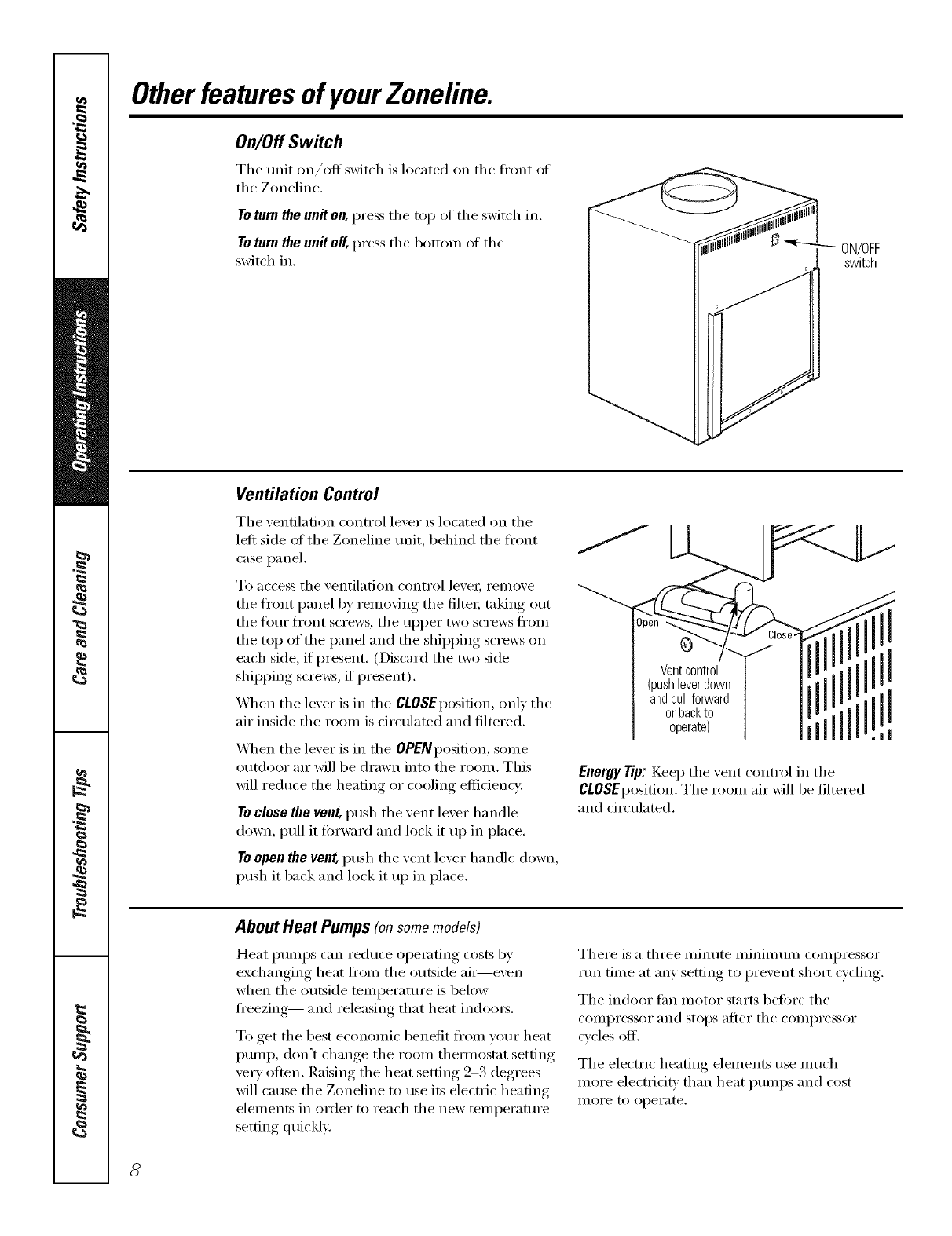
On/Off Switch
The unit on/oH' switch is located on the ti'ont oI
the Zoneline.
Toturn the unit on, press the top oI the switch in.
Toturn the unit of[, press the botton_ oI the
switch in. ON/OFF
switch
Ventilation Control
The ventilation control lever is located on the
left side ot the Zoneline unit, behind the ti'ont
case panel.
To access the ventilation control leve_; remove
the front panel by removing the filte_; taking out
the ti)m" ti'ont screws, the ul)per two screws ti'om
the top of the panel and the shipi)ing screws on
each side, if present. (Discard the two side
shipi)ing screws, if present).
_._]_en the lever is in the CLOSEposition, only the
air inside the room is circulated and filtered.
\._]]en the lever is in the OPEIVposition, some
outdoor air will be drawn into the room. This
will reduce the heating or cooling eflidencv.
Toclose the vent, push the vent lever handle
down, pull it fin'ward and lock it up in place.
Toopen the vent, push the vent lever handle down,
push it back and lock it up in place.
0
Ventcontrol
(pushleverdown
andpullforward
orbackto
operate)
Energy Tip: Kee I) the vent control in the
CLOSEposition. The room air will be filtered
and drculated.
AboutHeat Pumps(onsomemodels)
Heat pumps can reduce operating costs by
exchanging heat ti'om the outside air----even
when the outside temperature is below
fl'eezing-- and releasing that heat ind{){n_.
To get the best economic benefit ti'om yore" heat
I)ump, don't change the room themmstnt setting
very often. Raising the heat setting 2-3 degrees
will cause the Zoneline to use its electric heating
elements in order to reach the new temperature
setting quickly.
There is a three minute minimum compressor
mn time at any setting to prevent short cycling.
The indoor tim motor stnrts befin'e the
compressor and stops after the compressor
cycles off.
The electric heating elements use much
more electricity than heat i)umps and cost
II/OI'e to operate.
8

Careand cleaning, gecem
Turnthe Zoneline offand disconnectthepower supplybeforecleaning.
Indoor/Outdoor Coils
The exhaust coils on the Zoneline should be
checked regularly: If they are clogged with dirt or
soot, they may be protessionally steam cleaned by
w)ur (;E service center; You will need to remove
the refit fl'om the case to inspect the coils
because the dirt build-u I) occm_ on the
exhaust side.
-- Outdoor coils
Have the ceils cleaned regularl,_
Drain
Clean the drain system regularly to
prevent clogging.
Base Pan
In some installations, dirt or other debris may be
blown into the refit fl'om the outside and settle in
the base pan (the bottom of the refit).
In some areas of the United States, a "gelqike"
subst;mce may be present in the base pan.
Check it periodically and clean, if necessa_w:
Air Filters
To maintain optimum performance, change the filter at least every30 days.
The most important thing )'ou can do to Toremove
maintain the Zoneline is to change the filter at and replace
least eve_w 30 days. Dirty filte_ reduce cooling, the filter:
heating and air flow.
Changing the filter will: Decrease cost of operation,
save energai, prevent clogged heat exchanger
coils and reduce the risk ot premature
component tailm'e.
CAUTION: Oonot operate the
Zoneline wi_out the filter in place. If a filter
becomes torn or damaged, It should be replaced
immediately.
Operating without the filter in place or with a
damaged filter will allow dirt and dust to reach
the indoor coil and reduce the cooling, heating,
airflow and efficiency of the unit.
Replacement filtex_ should be imrchased fl'om
your local retailer where air conditioner and
lilI'IlaCe accessolJes are sold.
Filter size required is 20" x 20" x 1".
Filter
Remove filter
Unit-mounted filter
Filter
Returnairgrille Access-panelwith
returnair grille 9
Installation
Instructions Zoneline Air
Conditioners
Iouestions?Visit our Website at: ge.com or call 800.GE.CARES(800.432.2737).
BEFORE YOU BEGIN
Read these instructions completely and carefully.
• IMPORTANT -S.,ethese
instructions fin" local inspector's use.
• IMPORTANT - Obse,,e.ll
governing codes and ordinances.
•Note to Installer -Be sure to leave these
instructions with the owner.
• Note to Owner - Kee I) these instructions tot
fl]ture reference.
• Proper installation is the responsibility of the
installer.
"Product tailure due to improper installation is not
covered under the X_hrrantv.
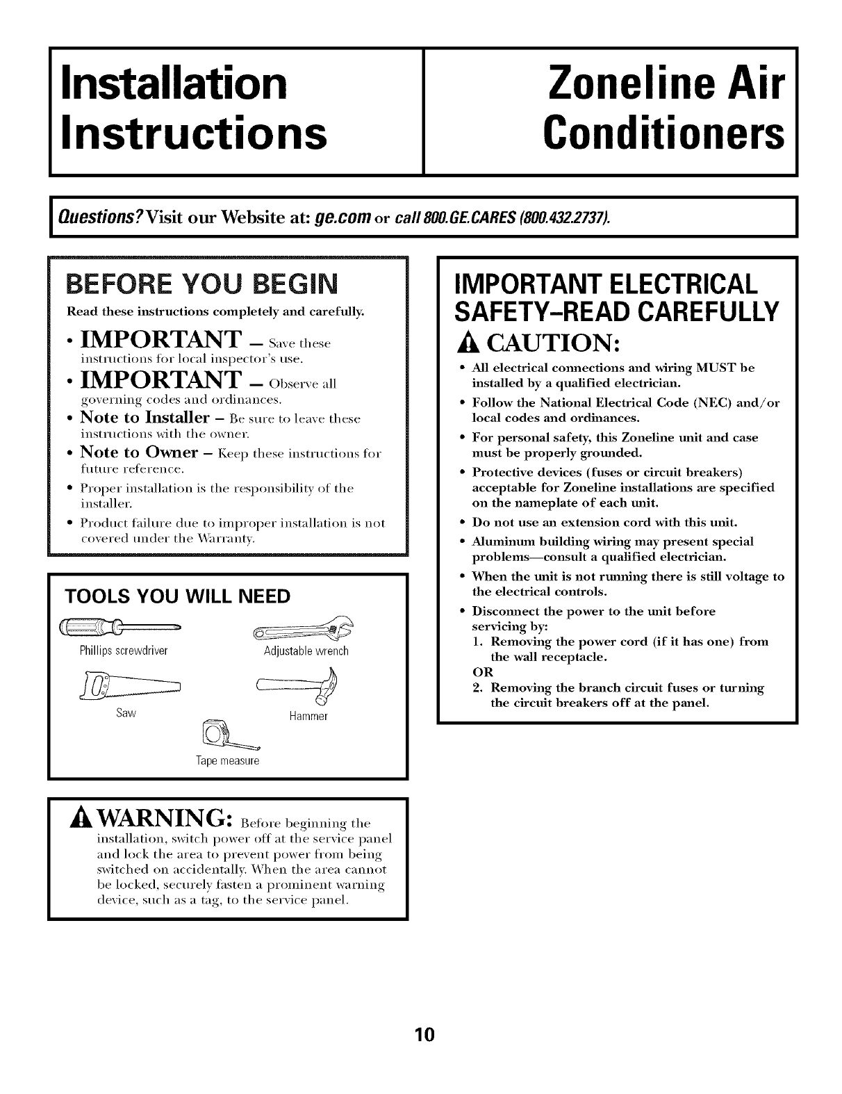
TOOLS YOU WILL NEED
Phillips screwdriver
Saw
Adjustable wrench
Hammer
Tapemeasure
IMPORTANT ELECTRICAL
SAFETY-READ CAREFULLY
CAUTION:
• All electrical cmmections and wiring MUST be
installed by a qualified electrician.
• Follow the National Electrical Code (NEC) and/or
local codes and ordinances.
•For personal safety, this Zoneline unit and case
must be properly grounded.
•Protective devices (fuses or circuit breakers)
acceptable for Zoneline installations axe specified
on the nameplate of each unit.
• Do not use ml extension cord with this unit.
• Aluminum building wiring may present special
problems--consult aqualified electrician.
• When the unit is not running there is still voltage to
the electrical controls.
Discmmect the power to the unit before
servicing by:
1. Removing the power cord (if it has one) from
the wall receptacle.
OR
2. Removing the brmlch circuit fuses or turning
the circuit breakers off at the pmlel.
I
^AUkWARNING: Bef,,,ebe_im,i.,_the
installation, switch power off at the service panel
and lock the area to prevent power from being
switched on accidentally. When the area cannot
be locked, secm'elv tasten a prominent warning
device, such as a tag, to the selwice panel.
10
Installation Instructions
ELECTRICAL REQUIREMENTS
•[)se ONlY the wiring size reconm/ended fin" single
outlet branch circuit.
•Proper current protection is the responsibility
of the owner.
Recommended branch circuit wire sizes*
Nameplate AWG Wire
maximum circuit size**
breaker size
15A 14
20A 12
30A 10
AWG -American Wire Gauge
Singlecircuit breaker from main box
** Based on copper wire, single insulated conductor at 60° C
NOTE: Use COl)per conductm_ only.
230/208 VOLT
ELECTRICAL SUPPLY
A power supi)ly kit must be used to supply power to fl_e
Zoneline trait. The appropfiam kit is detemfined by the
w)ltage, the means of electrical connection and the
amperage of the branch drcuit. See the PO_'ER
CONNECTION CHART on page 13 to select the
ai)i)ropriate kit.
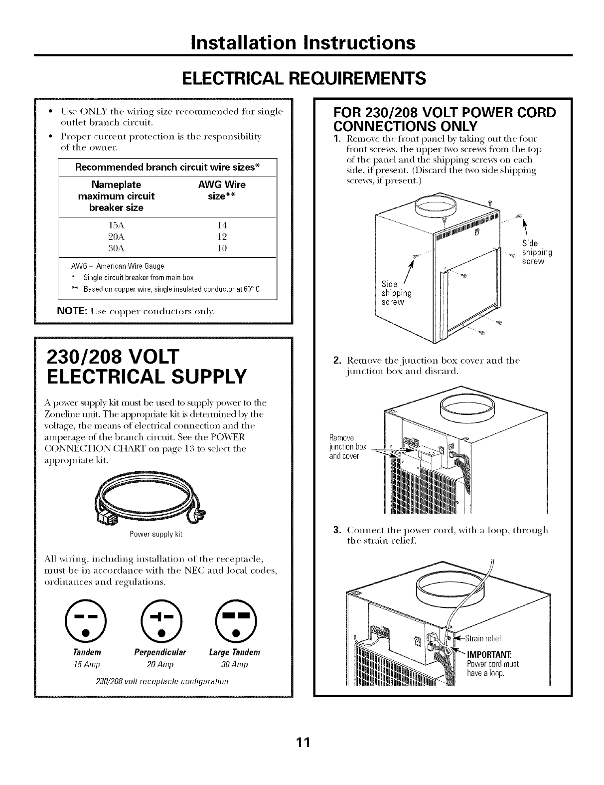
Power supply kit
M1 wirin , including installation of the receptacle,
must be in accordance with the NEC and local codes,
ordinances and regulations.
© © ©
Tandem Perpendicular Large Tandem
15Amp 20 Amp 30 Amp
230/208 volt receptacle configuration
FOR 230/208 VOLT POWER CORD
CONNECTIONS ONLY
1. Remove the tl"ont panel by taking out the tom"
fl'ont scre_vs, the uI)per two scre_v_ fl'om the top
of the panel and the shii)ping scre_vs on each
side, if present. (Discard the two side shii)ping
scrmvs, if present.)
Side
_, shipping
screw
2. ]).emoxe thejtmcti(m box coxer and the
jtmction box and discard.
Remove
junction box
and cover
3. Connect the power cord, with a loop, throm,h
the strain relief.
Powercordmust
havea loop.
11
Installation Instructions
DIRECT CONNECT APPLICATIONS
FOR 230/208 VOLT DIRECT
CONNECT APPLICATIONS ONLY
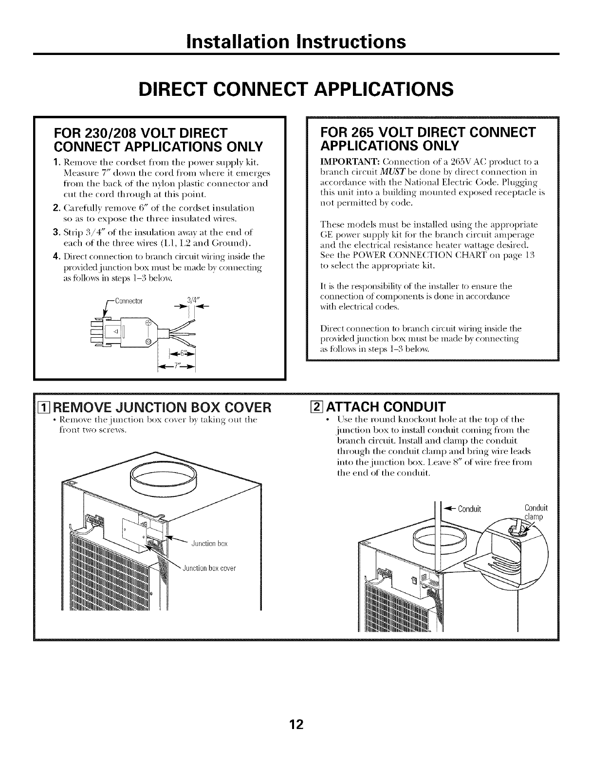
1. ]{emove the cordset fl'om the power supply kit.
Measure 7" down the cord fl'om where it emerges
fl'om the back of the nylon plastic connector and
cut the cord through at this point.
2. Careflfllv remove 6" of the cordset insulation
so as to expose the three insulated wires.
3. Strip 3/4" of the insulation away at the end of
each of the three wires (I,1, 1,9 and Ground).
4. Direct connection to branch circuit wiring inside the
provktedj unctkm box must be made b) connecting
as tbllo_:s in stops 1-3 below.
FOR 265 VOLT DIRECT CONNECT
APPLICATIONS ONLY
IMPORTANT: Connection of a 265V AC product to a
branch circuit MUST be done b) direct connection in
accordance with the Natkmal Electric Code. Plugging
this unit into a building mounted exposed receptacle is
not permitted b} code.
These models must be installed using the ai/propriate
GE power suppl? kit tot tile branch circuit amperage
and the electrical resistance heater wattage desired.
See the POWER CONNECTION (:HART on page 13
to select the al/propriate kit.
It is tile responsibilit) of tile installer to ensure tile
connection of con-}ponents is done ill accordance
with electrical codes.
Direct connection to branch circuit wiring inside the
proxidedjtmction box must be made b) connecting
as fi)llows in steps 1-,, beloxa
[] REMOVE JUNCTION BOX COVER
•Remo_e the junction box co_,er b) taking out the
t]'ont two screws.
[] ATTACH CONDUIT
• /_)se the round knockout hole at the toil of the
junction box to install conduit coming fl'om the
branch circuit. Install and clamp the conduit
through the conduit clamp and bring wire leads
into the j unction box. i,eave 8" ot wire fl'ee fl'om
the end of the conduit.
boxcover
Conduit Conduit
12
Installation Instructions
DIRECT CONNECT APPLICATIONS
[] MAKE WIRE LEAD CONNECTIONS INSIDE THE JUNCTION BOX
1. Make all wire connections bv using al_l_ropriate UiAisted electrical connecto_ and techniques.
2. Select the applicable wiring situation and tbllow the instructions accordingly:
1-Phase 220-240 VAC
1_Twn_o,r_e(:/i,_"//w Zone&w /o a si,@.J)hasv cir(ui@.
230V a/qdicalio_,_:
Omnect the white and black leads ot the Zoneline
power sui)ply kit to the branch circuit 1,1 and 1,2
leads. (The white lead of the power sui)ply kit should
be identified by the installer using electrical tape with
some color other than green or white.) Cmmect the
green lead ot the power sui)ply kit to the power
sui)ply and branch circuit gmtmd.
3-Phase 208 VAC
IUu,, (o,necti,g" the Zondim: to a thweJdu¢,v: ci*vuitJbr
208V a/qdicatio,,_:
Connect the white and black leads ot the Zoneline
power supply kit to the branch drcuit 1,1 and 1,2
leads. (The white lead of the power supply kit should
be identified by the installer using electrical tape with
some color other than green or white,) Connect the
green lead of the power supply kit to the power
supply and branch circuit ground.
3-Phase 208 VAC with "Crazy Leg"
//7wn _onn_(ling" the _mdine 10a gmu@hasv ci*_uit wilh
"(;mzr L_¢"Jbr 208V ap/)lk:ation,_:
Connect the white and black leads of the Zoneline
power supply kit to the branch drcuit Neutral and 1,1
leads. (The white lead dthe power supply kit should
be com_ected to neutral.) Cmmect the green lead of
the power supply kit m the power supply and branch
circuit grotmd.
3-Phase 253-277 VAC
IIIw. _onrwcii,g" the 7_mdim_ lo alh*_u@hasvcimuitJbr
265V ap/dicalio,s:
Connect the white and black leads of the Zoneline
power supply kit to the branch circuit Neutral and 1,1
leads. (The white lead dthe power supply kit should
be connected to neutral.) Connect the green lead of
the power supply kit to the power supply and branch
circuit grotmd.
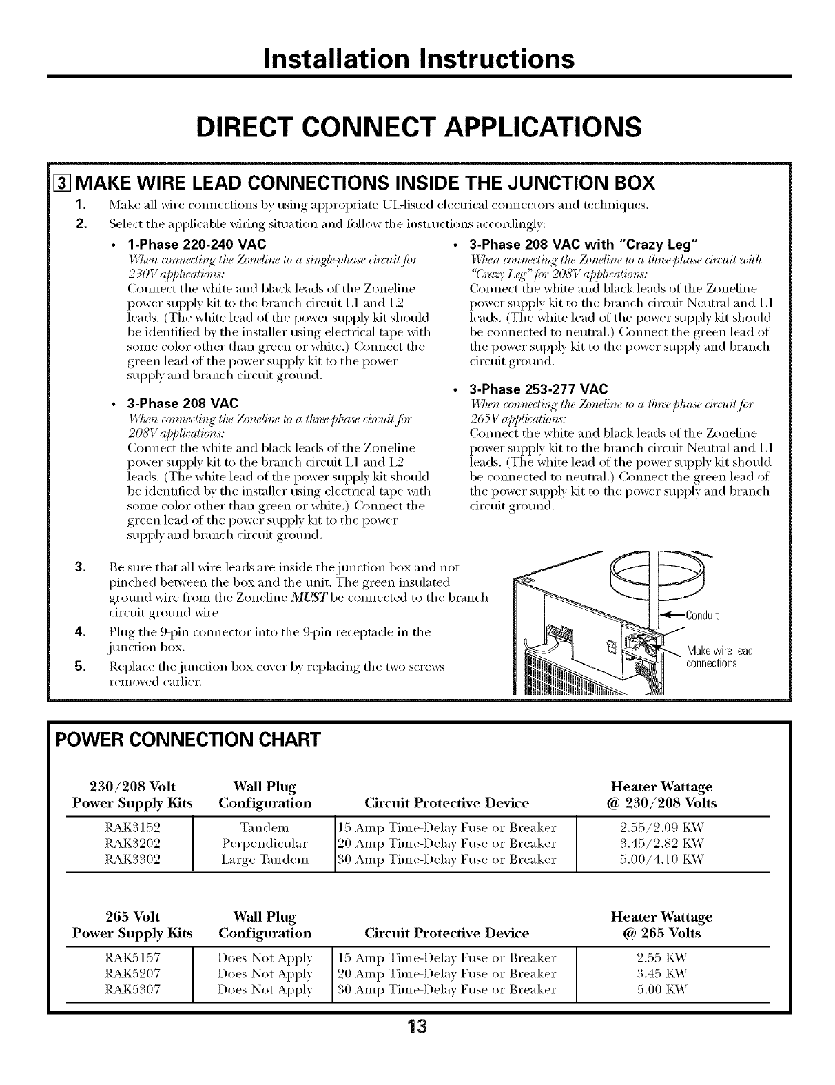
3. Be sure that all wire leads are inside thejtmction box and not
pinched between the box and the trait. The green insulated
grotmd wire from the Zoneline MUST be com_ected to the branch
circuit grotmd wire.
4. Plug the 9-pin c(mnector into the 9-pin receptacle in the
junction box.
5. Replace the junction box cover by replacing the two scre_vs
removed earlier:
bnduit
Makewire lead
connections
POWER CONNECTION CHART
230/208 Volt
Power Supply Kits
RAK3152
RAK3202
RAK3302
Wall Plug
Configuration
T_I n den/
Perpendicular
i,arge Tandem
Circuit Protective Device
15 Amp Time-Delay Fuse or Breaker
20 Amp Time-Delay Fuse or Breaker
30 Amp Time-Delay Fuse or Breaker
Heater Wattage
Ca)230/208 Volts
2.55/2.09 I_A_'
3.45/2.82 I_A_'
5.00/4.10 I_A_'
265 Volt Wall Plug Heater Wattage
Power Supply Kits Configuration Circuit Protective Device @ 265 Volts
RAK5157 Does Not Apply 15 Amp Time-Delay Fuse or Breaker 2.55 K_'
RAK5207 Does Not Apply 20 Amp Time-Delay Fuse or Breaker 3.45 K_'
RAK5307 Does Not Apply 30 Amp Time-Delay Fuse or Breaker 5.00 K_'
13
Installation Instructions
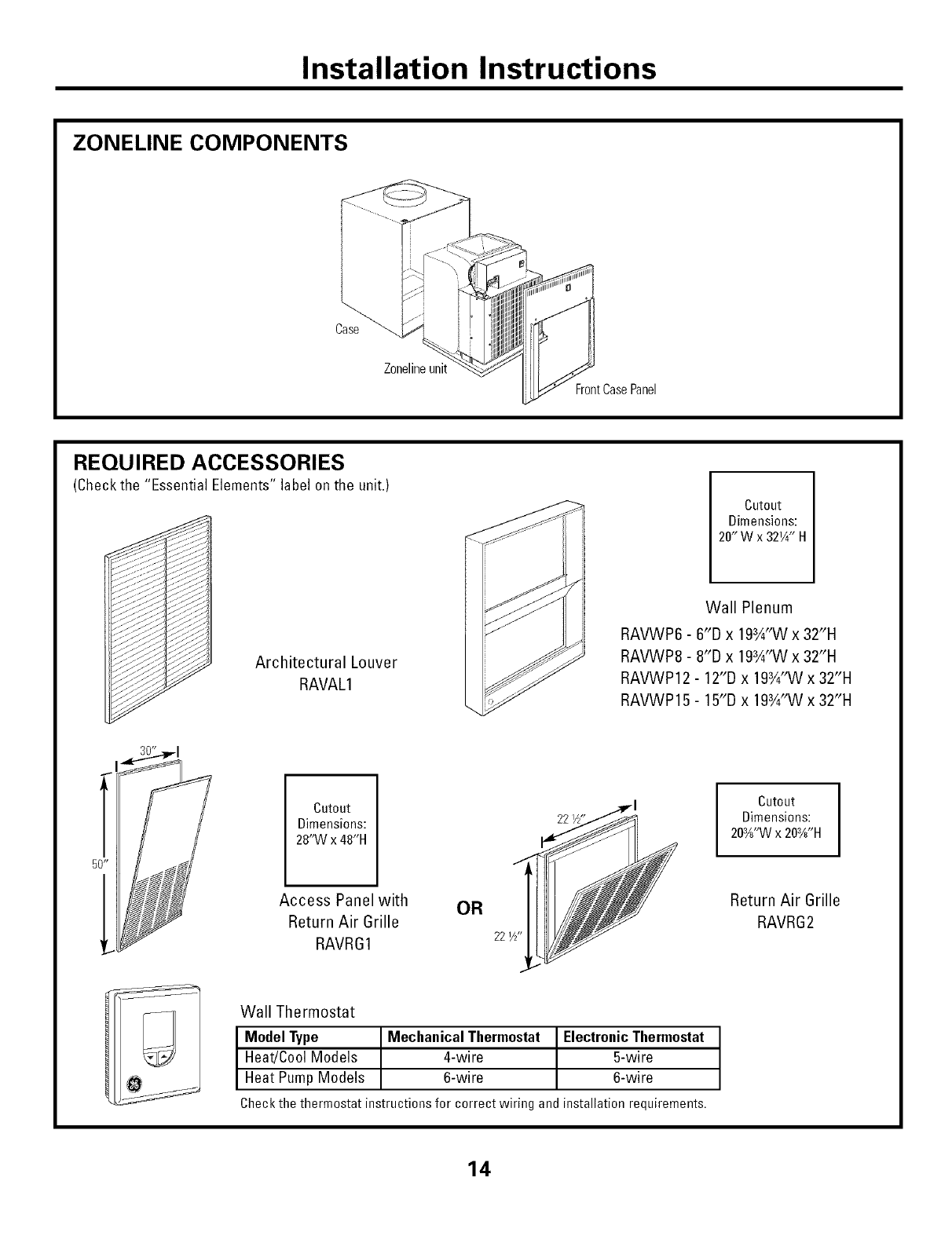
ZONELINE COMPONENTS
Case
Zonelineunit
FrontCase Panel
REQUIRED ACCESSORIES
(Check the "Essential Elements" label on the unit.)
ArchitecturalLouver
RAVAL1
Cutout
Dimensions:
20" W x 32W' H
Wall Plenum
RAVWP6 - 6"D x 193A'INx 32"H
RAVWP8 - 8"D x 193A"Wx 32"H
RAVWP12 - 12"D x 193/4'1Nx 32"H
RAVWP15 - 15"D x 193/4'1Nx 32"H
Cutout
Dimensions:
28'M/x 48"H
Access Panel with OR
Return Air Grille
RAVRG1 22i/z'
ICutout
Dimensions:
203/8"VVx 203X'H
Return Air Grille
RAVRG2
Wall Thermostat
Model Type Mechanical Thermostat Electronic Thermostat
Heat!Cool Models 4-wire 5-wire
Heat Pump Models 6-wire 6-wire
Check the thermostat instructions for correct wiring and installation requirements.
14
Installation Instructions
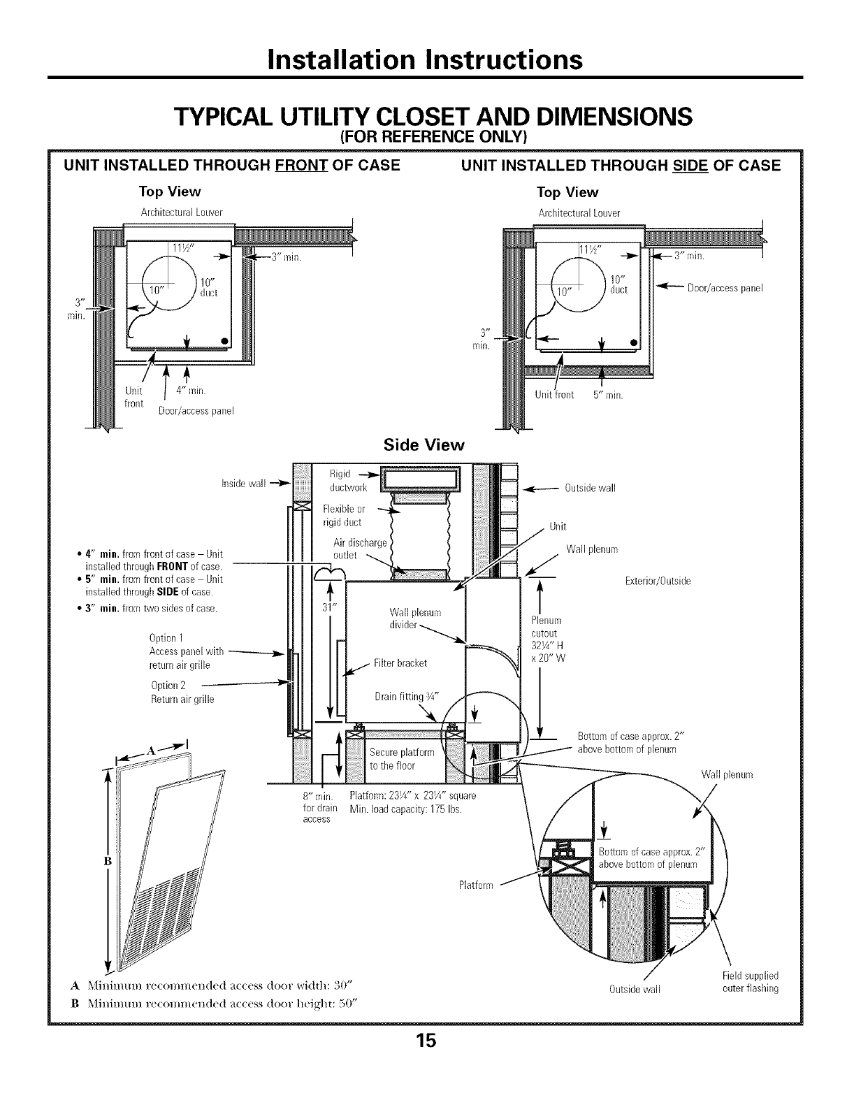
TYPICAL UTILITY CLOSET AND DIMENSIONS
(FOR REFERENCE ONLY)
UNIT INSTALLED THROUGH FRONT OF CASE UNIT INSTALLED THROUGH SIDE OF CASE
Top View Top View
Arcbitectural Louver ArchitecturalLouver
111/Z'
4" ffdn.
Door/access pauel
Insidewall
•4" min. fromfront of case Unit
installed throughFRONTof case.
•5" min. fromfront of case Unit
installed throughSIDEof case.
•3" min. from two sides of case.
Option1
Accesspanelwith
returnair grille
Option2
Returnair grille
3 _ _
rain.
Side View
Rigid --_
ductwork
Flexibleor _ /
rigid duct / /
Air discbarge_
_1" Wall plenum
a divider-.........__-. l
I F FHterbracket
;7--
pto t e f oor .....
8" rain. Platform:231/4"x 231/4" square
for drain Min. loadcapacity: 175Ibs.
access
t1:t
,_-- 3" rain.
D00r/accesspanel
Uuitfront 5" min.
Outsidewall
Unit
Wall plenum
/
l Exterior/Outside
Plenum
cutout
321/4"H
x20"W
Bottomof case approx.2"
/abovebottom of plenum
Wall plenum
Platform
A _([il/ir///lrll F(!COl//]//Clld(!d _tcc(_ss dooF _ldth" o0"
BMinimum re(ommended a((ess door heigl]u 50"
Fieldsupplied
Outsidewall outerflashiug
15
Installation Instructions
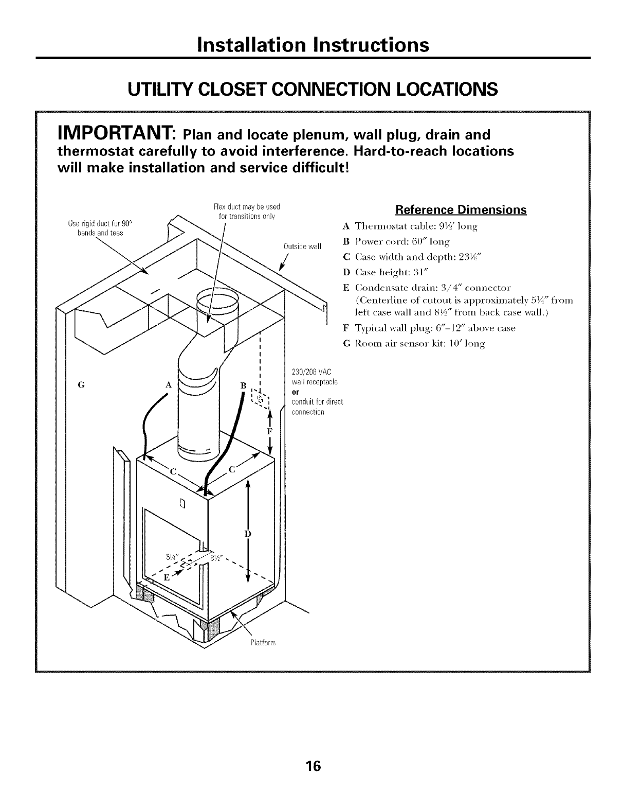
UTILITY CLOSET CONNECTION LOCATIONS
IMPORTANT: Plan and locate plenum, wall plug, drain and
thermostat carefully to avoid interference. Hard-to-reach locations
will make installation and service difficult!
Userigid ductfor 90°
bendsand tees
Flexduct roaybe used
for transitions only
Outsidewall
/
I
I
I
I
I
D
230/208VAC
wall receptacle
or
conduit for direct
connection
Reference Dimensions
A Them/ostat cable: 9½' long
BPower cord: 60" long
C Case width and depth: 23½"
D Case height: 31"
E (_ondensate drain: 3/4" connector
(Cei_terline of cutout is approxinmtely 5¼" from
left case wall and 8½" fl'om back case wall.)
F Typical wall plug: 6"-12" above case
G Room air sensor kit: 10' long
Platform
16
Installation Instructions
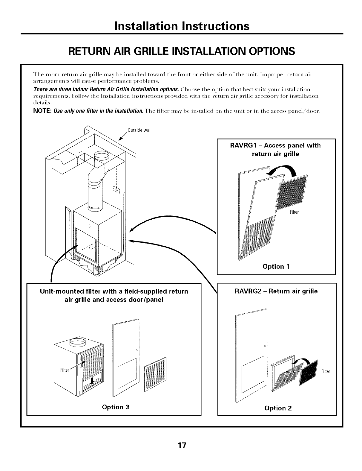
RETURN AIR GRILLE INSTALLATION OPTIONS
The room return air grille may be installed toward the fl'ont or either side of the unit. ]ml)roper return air
arrangements will cause perfi)m/ance problems,
There are three indoor Return Air Grille Installation options. Choose the option that best suits w)ur installation
requirements, Follow the Installation Instructions i)rovided with the return air grille accessory for installation
details,
NOTE: Use only one filter in the installation.The filter ma_ be installed on the unit or in the access panel/door.
Outside wall
RAVRG1 - Access panel with
return air grille
/
Option 1
Unit-mounted filter with a field-supplied return
air grille and access door/panel
Option 3
RAVRG2 - Return air grille
Option 2
Filter
17
Installation Instructions
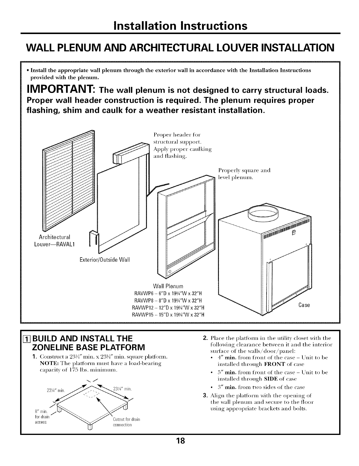
WALL PLENUM AND ARCHITECTURAL LOUVER INSTALLATION
•Install the appropriate wall plenum through the exterior wall in accordance with the Installation Instructions
provided with the plenmn.
IMPORTANT: The wall plenum is not designed to carry structural loads.
Proper wall header construction is required. The plenum requires proper
flashing, shim and caulk for a weather resistant installation.
Proper header for
structural support.
Apply proper caulking
and flashing.
Properly square and
lexel plenmn.
Architectural
Louver--RAVAL1
Exterior/0utside Wall
Wall Plenum
RAVWP6- 6"D x 19¾"VVx 32"14
RAVWP8- 8"D x 19¾"VVx 32"14
RAVWP12- 12"D x 19¾"VVx 32"14 Case
RAVWP15- 15"D x 19¾"Wx 32"14
[] BUILD AND INSTALL THE
ZONELINE BASE PLATFORM
1. Construct a 23V(' rain. x 23¼" rain. square pladimu.
NOTE: The platform must have a load-bearing
capacity of 175 lbs. minimum.
-..J
\S
8" rain: /
:;:de::m M'J __/'_Qlt0ut;pr drail,
COllll_CtlO[1
2. Place the platfimn in the utiliW closet with the
following clearance between it and the interior
surface of the walls/door/panel:
• 4" rain. ti'om front of the case - Unit to be
installed through FRONT of case
• 5" rain. fl'om front of the case - Unit to be
installed through SIDE of case
• 3" rain. fl'om two sides of the case
3. Align the platflmu with the oI)eniw,_ of
the wall plenum and secm'e to the floor
using appropriate brackets and bolts.
18
Installation Instructions
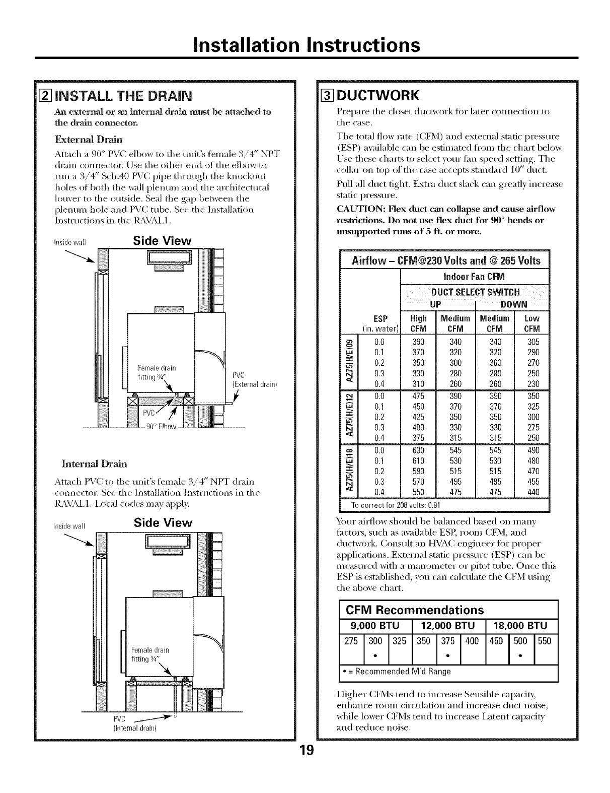
[] iNSTALL THE DRAIN
An externaJ or an internal drain must be attached to
the drain connector.
F_ternal Drain
Attach a 90 ° PVC elbow to the unit's fbmale 3/4" NPT
chain connecto_ Use the other end of the elbow to
run a 3/4" Sch.40 PVC pipe through the knockout
holes of both the wall plenum and the architectural
louver to the outside. Seal the gap between the
plenum hole and PVC tube. See the Installation
Instructions in the Ig_,VAL1.
Insidewall Side View
90° Elbow
iiiiiiiiiNIIN==
iiiiiiiiiJN==
iiiiiiiiiNIl_
HHHHi_
iiiiiiiiilllll===
HHHH_Ia_
PVC
(Externaldrain)
J
iiiiiiiIIm===
Internal Drain
Attach PVC to the unit's female '_ " )
.,/4 NIT drain
com_ector. See the Installation Instructions in the
IL_VAL1. Local codes ma)apply.
Insidewall Side View
PVC ....------"_J'_:'
(Internaldrain)
[] DUCTWORK
Prepare the closet ductwork for later com_ection to
the case.
The total flow rate (C[q¥1) and external static pressure
(ESP) ax:dlable can be estimated ti'om the chart below.
Use these charts to select your lira sl)eed setting. The
collar on top _ff the case accepts standard 10" duct.
Pull all duct tight. Extra duct slack can greatly increase
static pressure.
CAUTION: Flex duct can collapse mad cause airflow
restrictions. Do not use flex duct for 90 ° bends or
mlsupported rmls of 5 ft. or more.
19
Airflow -CFM@230 Volts and @ 265 Volts
indoor Fan CFM
swITc.
UP IDOWN
ESP High Medium Medium Low
(in.water) CFM CFM CFM CFM
0.0 390 340 340 305
0.1 370 320 320 290
0.2 350 300 300 270
0.3 330 280 280 250
'_ 0.4 310 260 260 230
0.0 475 390 390 350
0.1 450 370 370 325
0.2 425 350 350 300
Da 0.3 400 330 330 275
<0.4 375 315 315 250
0.0 630 545 545 490
0.1 610 530 530 480
=: 0.2 590 515 515 470
Da 0.3 570 495 495 455
<0.4 550 475 475 440
To correct for 208volts: 0.91
Your ai_low should be balanced based on many
fi_cto_, such as available ESP, room CFM, and
ductwork. Consult an HVAC engineer fi)r proper
applications. External static pressure (ESP) can be
measured with a manometer or pitot tube. Once this
ESP is established, you can calculate the CFM using
the above chart.
CFM Recommendations
=Recommended Mid Range
Higher CFMs tend to increase Sensible capadb;
enhance room circulation and increase duct noise,
while lower C[q¥1s tend to increase i,atent capacib'
and reduce noise.
Installation Instructions
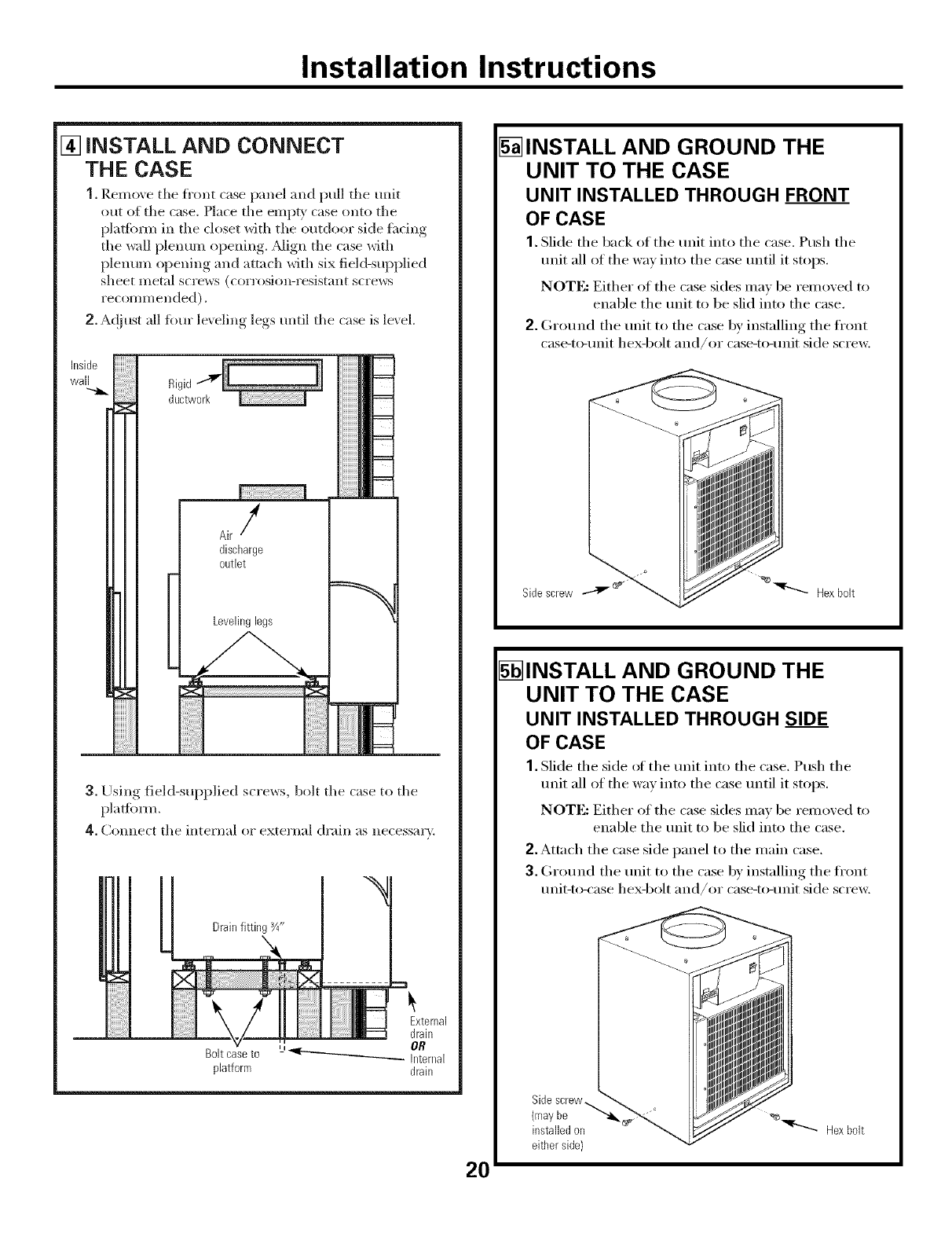
[] iNSTALL AND CONNECT
THE CASE
1. Remove tile fl'ont case panel and pull the unit
ot/t of the case. Place tile empty case onto tile
plat]onn in the closet with tile outdoor side fl*dng
tile wall plentun opening. _Mign the case _th
plenum ol)ening and attach with six field-supplied
sheet metal scI'ews (corl'oSiOl]-I'esistant screws
I'ecoml't] ended).
2. A<!}ust all fimr leveling legs until tile case is le\ el.
Inside
wall
Air/
discharge
outlet
Levelinglegs
3. -Using field-supplied screws, bolt tile case to tile
plalfb_n.
4. Connect tile internal o_ external drain as necessary.
Boltcaseto
platform
5_INSTALL AND GROUND THE
UNIT TO THE CASE
UNIT INSTALLED THROUGH FRONT
OF CASE
1. Slide tile back oI tile unit into tile case. Push tile
unit all of tile way into tile case until it stops.
NOTE: Either of tile case sides may be removed to
enable tile unit to be slid into tile case.
2. Ground tile unit to tile case by installing the fl'ont
case-to-unit hex-bolt and/or case-to-unit side screw,
Sidescrew "_"_ Hexbolt
5_INSTALL AND GROUND THE
UNIT TO THE CASE
UNIT INSTALLED THROUGH SIDE
OF CASE
1. Slide tile side ot tile unit into tile case. Push tile
unit all of tile way into tile case until it stops.
NOTE: Either of tile case sides may be removed to
enable the unit to be slid into the case.
2. Attach the case side panel to the main case.
3. Ground tile unit to tile case by installing tile fl'ont
unit-to-case hex-bolt and/or case-to-unit side scre_:
20
Sidescrew_
(mayhe
installed on _r---..._. Hexbolt
either side}
Installation Instructions
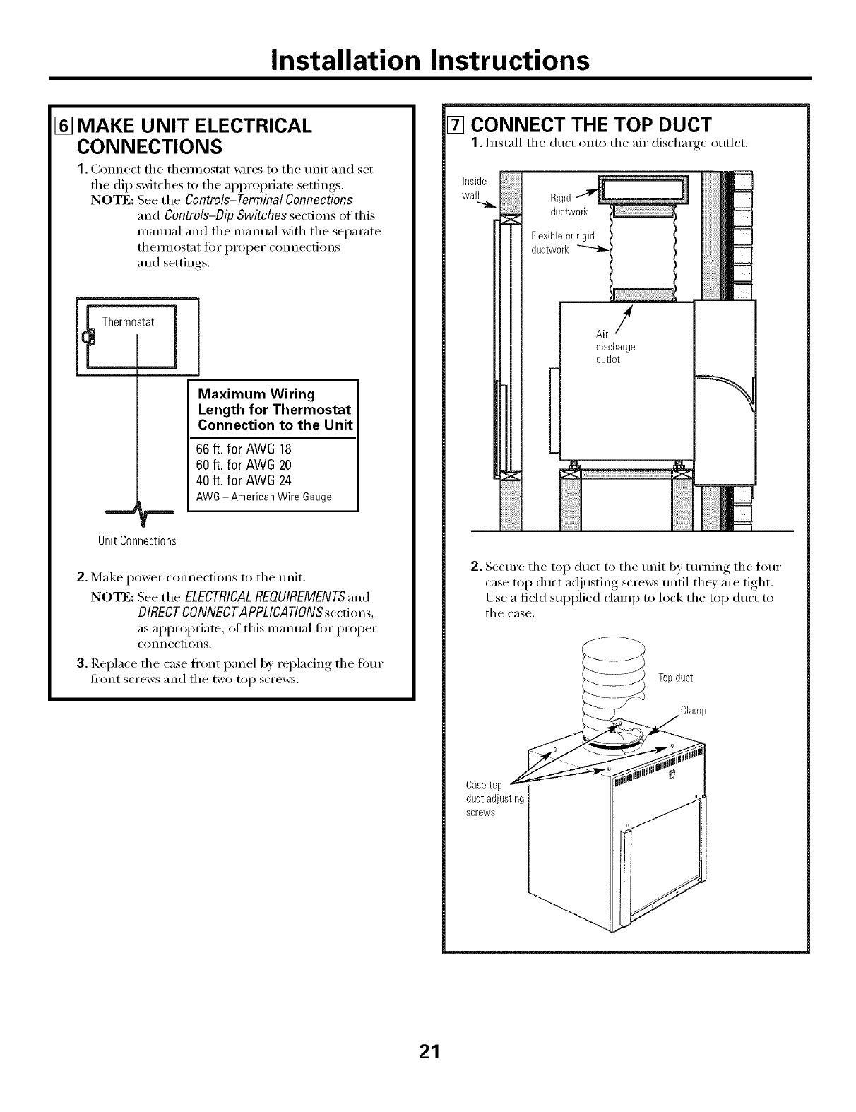
[] MAKE UNIT ELECTRICAL
CONNECTIONS
1. Connect tile themlostat wires to tile unit and set
tile dip switches to tile appropriate settings.
NOTE: See the Controls-TerminalConnections
and Controls-Dip Switches sect.ions of this
mmmal and tile manual with tile separate
thellilOstat ti)i" proper connections
and settings.
Thermostat ]
--r
Unit Connections
Maximum Wiring
Length for Thermostat
Connection to the Unit
66 ft. for AW6 18
60 ft. for AW6 20
40 ft. for AW6 24
AWG AmericanWire Gauge
2. Make power connections to tile trait.
No'rE: See tile ELECTRICALREOUIREMENTS',md
DIRECT CONNECTAPPLICATIONS secdons,
as appropriate, ot this inanual for proper
connections.
3. Replace tile case fl'ont panel b)' replacing tile four
Ji'ont ScI'eWS }lll(l tile two top scre_vs.
[] CONNECT THE TOP DUCT
1. Install tile duct onto tile air discharge outlet.
i!;i!;i!;i!;i!;i!;ii
i
Flexibleorrigid
ducWvork_ '
Airf
discharge
outlet
2. Secm'e tile top duct to tile trait by tm'ning tile fl)m"
case top duct a(!justing scre_vs tmtil they are tight.
Use a field supplied clamp to lock tile top dtlct to
tile case.
Casetop
ductadjusting
screws
Topduct
Clamp
21
Installation Instructions
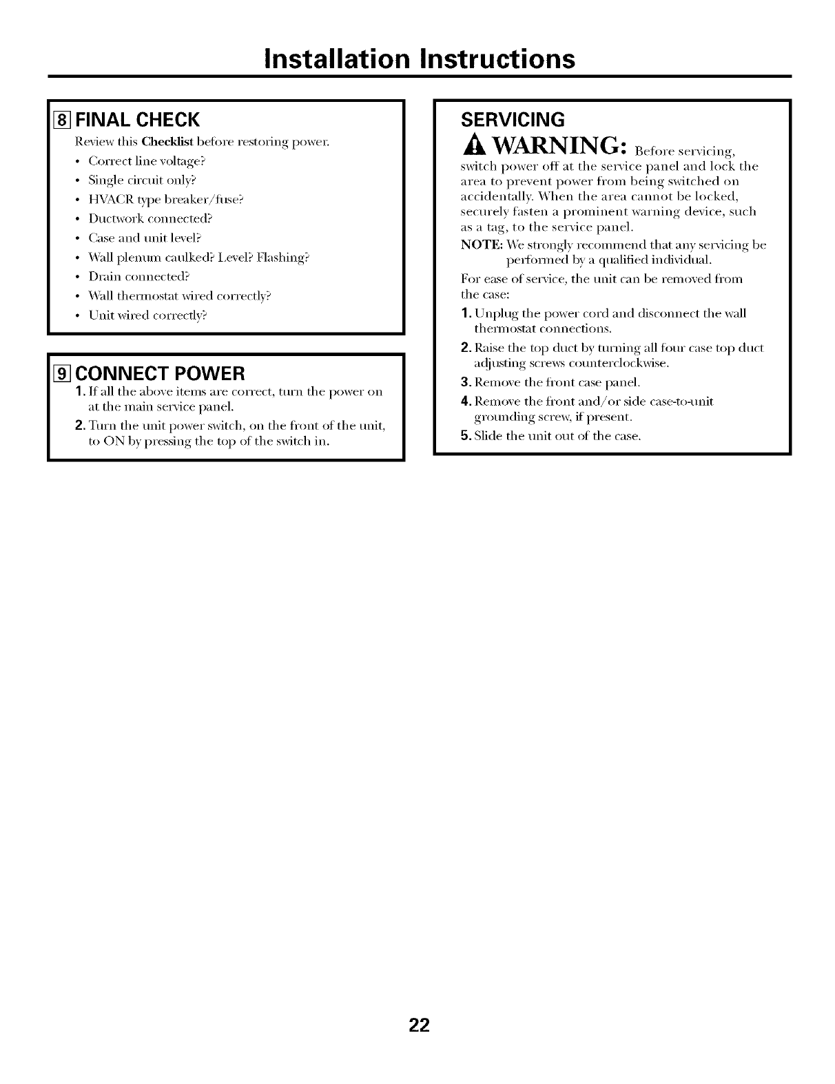
[] FINAL CHECK
Review this Checklist before restoring power:
•Correct line voltage?
• Single circuit only?
• HVACR _'pe breaker/fllse?
• Ductwork connected?
• Case and unit level?
• Wdl plenum caulked? I,evel? Flashing?
• Drain connected?
• _4all them_ostat wired correctly?
• Unit wi_ed correcflv?
[] CONNECT POWER
1. If all tile above items are correct, tm'n tile power on
at tile main service panel.
2. Turn tile unit power switch, on tile fl'ont of tile unit,
to ON by pressing the top of the switch in.
SERVICING
./kWARNING: Before ser\icing,
switch power off at the service panel and lock the
area to prevent power fl'om being switched on
accidentally. When the area cammt be locked,
securely fasten a prominent warning device, such
as a tag, to the service panel.
NOTE: We strongly recommend that any se_Mcing be
pe_tmmed bv a qualified individual.
For ease of service, tile trait can be removed fl'om
the case:
1. Unplug tile power cord and disc(mnect tile wall
them]ostat C()IlIlec[i()IIS,
2. Raise tile top duct by turning all fl)m" case top duct
a(!iusting screws co/mterclockwise,
3. Remove the fl'ont case panel,
4. Remove tile fl'ont and/or side case-to-refit
gro/mding scre_, if present.
5. Slide the unit out ot the case.
22
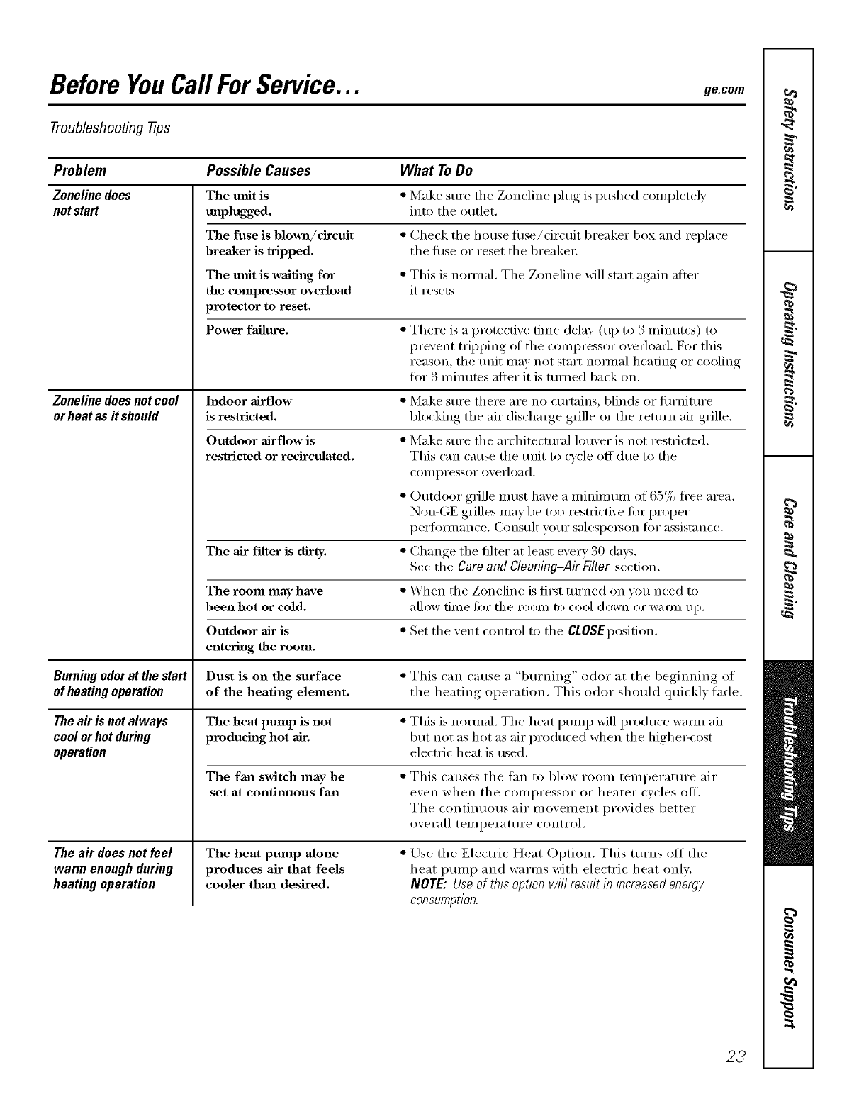
Before YouCall ForService... ge.om
Troubleshooting -tips
Problem Possible Causes What ToDo
Zoneline does The unit is *Make sure tile Zoneline plug is pushed comi)letely
notstart maplugged, into tile outlet.
The fuse is blown/dreuit *Check tile house filse/circuit breaker box and replace
breaker is tripped, the filse or reset the breakei:
The unit is waiting for • This is hernial. The Zoneline will start again atter
the compressor overload it resets.
protector to reset,
Power failure, • There is a protective tilne delay (up to 3 ininutes) to
prevent tI_ipping of tile compressor overload. For this
reason, tile unit may not start noi-/nal heating or cooling
fi)r 3 Ininutes atter it is turned back on.
Zoneline does not cool Indoor airflow
orheatas it should is restricted.
Outdoor airflow is
restricted or recirculated.
• Make sure there are no ctmains, blinds or fiu'niture
blocking the air dischaxge grille or the returxl air grille.
• Make sure tile ax'chitectux'al louver is not restricted.
This can cause tile unit to cycle off due to tile
COlI/i)l'eSSOl" overload.
• Outdoor grille lnust have a uliniu/uln of 65% fl'ee area.
Non-GE grilles may be too restrictive tor proper
perfinmance. Consult your salespei_on tor assistance.
• Change the filmr at least every 30 days.
See the Care and Cleaning-Air Filter section.
• When the Zoneline is fii_t turned oil vou need to
allow tilne tor tile l'OOlU to COO1 down oi" W_ilIU Ill),
• Set tile vent control to tile ClOSEposition.
The air filter is dirty,
The room may have
been hot or cold.
Outdoor air is
entering the room.
Burning odorat the start Dust is on the surface • This can cause a "burning" odor at tile beginning of
of heatingoperation of the heating element, tile heating operation. This odor should quickly lade.
The air is not always The heat pinup is not • This is hernial. Tile heat i)ump will produce wmm air
cool orhot during producing hot air, but not as hot as air produced when tile higheI_cost
operation electric heat is used.
The fma switch may be • This causes tile fan to blow roonl telnl)erature air
set at continuous fan even when tile colnl)ressor or heater cvcles off.
The continuous air n/ovelnent provides better
overall telni)erature control.
The heat pump alone
produces air that feels
cooler thm_ desired.
The a# does not feel
warm enough during
heating operation
• Use tile Electric Heat Option. This turns off tile
heat I)tunI ) and warlns with electric heat only.
NOTE: Useof this option will resultin increasedenergy
consumption.
23
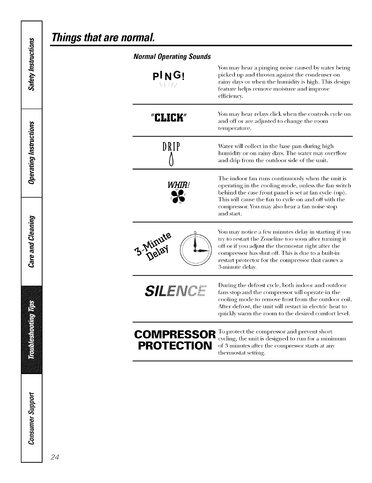
Thingsthatare normal
Normal Operating Sounds
PING! You may hear a pinging noise caused by water being
picked up and thrown against tile condenser on
rainy days or when the humidi b' is high. This design
teature helps relnove moisture and improve
etticiencv.
"CLICK" You ma) hear rela)_ click when tile controls cxcle on
and otI or are a(!iusted to change tile room
temperature.
DRIP
6X4_ter will collect in tile base pan during high
humidit_ or on raim days. Tile water may oxertlow
and drip fl'om tile outd(>(>r side of tile unit.
WHIR! Tile indoor tim runs continuously when tile unit is
operating in tile cooling mode, unless tile tim switch
behind tile case fl'ont panel is set at tim cycle (up).
This will cause the tim to cycle on and off with the
COIlll)I'eSSOI: roll Ill[ly also hear a thn noise stop
and staY[.
_t
Ym may notice a tew minutes delay in starting if w_u
ti T to restart tile Zoneline too soon after turning it
oIt or if you a(!iust tile them/ostat right alter tile
compressor has shut off. This is due to a built-in
i'est;irt protector tor tile COilll)i'essor that catises a
3-minute delay.
During tile defl'ost cycle, both indoor and outdoor
tiros stop and tile compressor will operate in tile
cooling illode to i'eil/ove ti'ost J[i'Oiil tile o/lt(loor coil.
_Mfer defl'ost, tile unit will restart in electric heat to
quickly wmm the room to the desired comiort level.
COMPRESSOR T,.pi.tectthec..mi,ie_,,i;,.dl)rexent short
c) cling, tile unit is designed to run fin" a minimum
PROTECTION '":_mi.,/te__,,ei"tilecoinl)ressorstarts at any
them_ostat setting.
24
*_ Ct/t here
Please place in envelope and mail to:
General Electric Company
Warranty Registration Department
P.O. Box 32150
Louisville, KY 40232-2150
25

Consumer Product Ownership Registration
Dear Customer:
Thank you tbr purchasing our product and thank you for placing your confidence in us.
X&'eare proud to haxe you as a customer'.
Follow these three steps to protect your new appliance investment:
Complete and mail
your Consumer
Product Ownership
Registration today:
IL_v_, th,_,l)_,_c_, of
mind of knowiHg we
Call COllt_tct VOI/ ill
the unlik(_ly event of a
sat_.*ty moditication.
At]er mailing the
re_gistration below,
store this document
ill a saf;_'place. It
contains information
you will need should
you reqtlire service.
Our service mlml)er is
800.GE.CARES
(800.432.2737).
Read VOllr ()%%-11e1-_s
Manual caretilllv
It will hel l)you
operate VOlll" ll('_"
appliance prope rlT_;
Model Number Serial Number
IIIII
Important: If you did not get a registration card with your
product, detach and return the form below to
ensure that your product is registered, or register
online at ge.com. ._,.._ Cut ll(_r(_
Consumer Product Ownership Registration
Model Number Serial Number
M_ his. Mrs. Miss
First] ] List ]
N_mle IIIIIIIII Nam( I I I I I I I I I I I I
Str(( t [
Address IIIIIIIIIII IIIIIIIIIIIII
, I
I
I
,_p,#I,,,,ii,IE-mail,\cldr<ss,:_
GE Consumer & Industrial
Appliances
General Electric Compang
Louisville, KY/40225
ge.com
26
'_'Please provi(le your e-mail address to receive, via e-mail, (liscounts, sp_cial otl;_rs and other
important colmmmications ti-om (;E Applia_lces ((;EA).
Check here if you (lo not want to receive communications fkom (;EA's caretilllv select(d
partners.
FAILL RE TO COMPLETE AND RETI RN Tt tlS CARD DOES NOT DIMINISt t g()l R
W.\RI_ \N'[_" RIGt ITS.
For intk_rmation al_out (,EA's privacy and data usage policy, go to ge.com and click oll
'Prixacy Policy" or call 800.6'_)6.2224.
I
I
VerticaIZoneline Warranty.
All warranty service provided by our Factory Service Centers,
or an authorized Customer Care®technician. To schedule
service, on-line, 24 hours a day, vis# us at go.cam, or call
800.GE.CARES(800.432.2737). For service in Canada, call
1.800.361.3400.Please have serial number and model
number available when calling for service.
Staple your receipt here.
Proof of the original purchase
date is needed to obtain service
under the warranty
ForThe PeriodOf:
One Year
From the date of the
original purchase
Five Years
From the date of the
original purchase
Five Years
Fromthe date of the
originalpurchase
GEWill Replace:
Anypart(,t the Z(meline which ti=ils due to a detect in mliterials or workmanship. During this
Ignited one-year warranty, GE will also provide, free of charge, all labor and related service to
replace the de_bctive part.
Any part of the sealed refrigerating system (the compresso_; condense1; ex_q_orator and all
connecting robing) which fidls due to a detect in materials or workmanship. Dudng this
four-year limited additional warranty, GE will also provide, free of charge, all labor
and related service to replace the defective pm_.
For the second through the fifth yearKom the (late of original purchase, GE will replace
certain parts that fidl due to a defect in materials or worl<manship. Pm_s covered are iim
motol_, switches, thermostats, heatei; heater protectol% compiessor overload, solenoids,
drcuit boards, au_liary controls, thermistors, Ks)st contI'OIs, ICR pump, capacitor5, Val'iStolN
and indoor blower bea_ing. During this four-year I#nited additional warranty, you will be
responsible tar any labor or on-site service costs.
What GE Will Not Cover:
•Service trips to your site to teach you how to use the
product.
•Improper installation, delivery or ma'_mtenmace.
If you have an h_staJlation problem, or if the Mr
conditioner is of improper cooling or heating capacity
for the intended use, contact your dealer or hlstaller.
You are responsible for providing adequate electrical
comlecth_g facilities.
• In commercial locations, labor necessary to move the
unit to a location where it is accessible for service by ml
hldJviduaJ teclnficimL
•Failure or dmnage resulting from corrosion due to
installation in ml enviromnent containing corrosive
chemicals.
•Replacement of fuses or resetting of circuit breakers.
•Vdters.
•FaJhtre of the product resulting from modifications to
the product or due to unreasonable use including
failure to provide reasonable m_d necessary
maJlltenaJlce,
• Failure or dmnage resuith_g from corrosion due to
h_staJlation in a coastaJ enviromnent, except for models
weated with special factory-applied m_ti-corrosion
protection as designated in the model number.
• Damage to product caused by improper power supply
voltage, accident, fire, floods or acts of God.
• Incidental or consequentiM damage caused by possible
defects with this air conditioner.
• Damage caused after delivery.
• Product not accessible to provide required service.
IXCLUSION OFIMPLIED WARRANTIES--Your sole and exclusive remedy is product repa# as provided hi this Lim#ed
Warranty.Any implied warranties, inclodiug the implied warranties of merchantability or fitness for a particular purpose,
are limited to one year or the shortestperiod allowed by law.
This warranty is extended to the original purchaser and any succeeding owner for products purchased for
use within the USA and Canada. If the product is located in an area where service by a GEAuthorized Servicer
is not available, you may be responsible for a trip charge or you may be required to bring the product to an
Authorized GE Service location for service. In Alaska, the warranty excludes the cost of shipping or service
calls to your site.
Some states or provinces do not allow the exclusion or limitation of incidental or consequential damages.
This warranty gives you specific legal rights, and you may also have other rights which vary from state to state
or province to province. To know what your legal rights are, consult your local, state or provincial consumer
affairs office or your state's Attorney General
Warrantor: General Electric Company. Louisville, KY 40225 2 7
ConsumerSupport.
gEAppliancesWebsite ge.com
Have a question or need assistance with your appliance? Try tile GE Appliances Website 24 hom_ a day,
any day of tile year! For greater convenience and taster serxJce, you can now download Owner's Manuals,
order parts, cat;dogs, or even schedule service ondine. You can also "_sk Ore" Team of EN)erts ......
yo/Ir qtlestions, and so II/{lcl/II/ore...
ScheduleService
Expert (;E repair se_sice is only one step awm fl'om veto" doo_: Get on-line and schedule veto" serxice at
( " 1
veto" comenience 24 hems any day )f tile vea_ Or call 800.(;E.CARES (800.432.2737) (hmng nomml
business hems.
ge.com
RealLifeDesignStudio ge.com
GE supports tile ILrnive_al Design concept--products, services and enviromnents that can be used by
people of all ages, sizes and capabilities. _\'e recognize tile need to design fi)r a wide range of ph}:sical and
mental abilities and impaim_ents. For details of GE's Universal Design applications, including kitchen
design ideas fin" people with disabilities, check out o/ir X,Vebsim today. For tile heating impaired, please call
800.TDD.GEAC (800.833.4322).
PartsandAccessories ge.com
Individuals qualified m se_'ice their own appliances can have parts or accessories sent directly to their
homes (VISA, MasterCard and Discover cards are accepted). Order on-line today, 24 hom_ eve_a' day or by
phone at 800.626.2002 dining nomml business hom_.
Instructions contained in this manual cover procedures to be performed by any user. Other servicing generally
should be referred to qualified service personnel. Cautionmust be exercised, since improper servicing may cause
unsafe operation.
ContactUs ge.com
If you are not satisfied with tile service w)u receive fl'om GE, contact us on our X'Vebsite with all tile details
including your phone ntlll/beI; or wlJte to: (;eneral Manage_; C/lStOll/ei" Relations
GE Appliances, Appliance Park
I,ouisville, KY 40225
RegisterYourApplbnce
Register your new applimlce on-lille---at your convenience! Timel) product registration will allow fin.
enhanced ('oi//illtlni('ation and prolllpt service tinder tile telI//s of _o/Ir WalTallt} _, should tile need alJse.
You may also mail in tile pre-pfinted registration card included in tile I)ackim"_ material.
ge.com
Printed in China
