GE CSA1201RSS01 User Manual MICROWAVE Manuals And Guides 1011697L
User Manual: GE CSA1201RSS01 CSA1201RSS01 GE MICROWAVE - Manuals and Guides View the owners manual for your GE MICROWAVE #CSA1201RSS01. Home:Kitchen Appliance Parts:GE Parts:GE MICROWAVE Manual
Open the PDF directly: View PDF ![]() .
.
Page Count: 48
Installation
Instructions Above the
Cooktop Oven
PVM1790, PSA1200,PSA2200
IQuestions? Call 800.GE.CARES (800.432.2737) or visitour Websiteat: GEAppliances.com I
BEFORE YOU BEGIN
Read these instructions completelg and carefullg.
IMPORTANT - Sovethese
instructions for Iocol inspector's use.
• IMPORTANT - Observeoli
governingcodesond ordinonces
• Note to Installer- Be sureto leovethese
instructionswiththeConsumer
Note to Consumer - Keepthese instructions
for future reference.
Skill level - Instollotion of this opplionce requires bosic
mechonicol ond electricol skills.
Proper instollotion is the responsibility of the instoller.
Product foilure due to improper instollotion is not
covered under the Worrontg.
©
LA SECCION EN ESPANOL EMPIEZA
EN LA PAGINA 25.
READ CAREFULLY.
KEEP THESE INSTRUCTIONS.
Installation Instructions
CONTENTS
General information
Important Safetg Instructions ......................................3
Electrical Requirements ..................................................3
Hood Exhaust ................................................................4, 5
Damage - Shipment/Installation ..................................6
Parts Included ..................................................................6
Tools You Will Need ..........................................................7
Mounting Space ................................................................7
Step-bg-step installation guide
Placement of Mounting Plate ..................................8-10
Removing the Mounting Plate ............................8
Finding the Wall Studs..........................................8
Determining Wall Plate Location ........................9
Aligning the Wall Plate ......................................10
Installation Tgpes ....................................................11-22
[_ Outside Top ....................................
Exhaust 12-14
Attach Mounting Plate to Wall ................12
Preparation of Top Cabinet ......................13
Assemble and Install Adaptor ..................13
Mount the Oven ..................................13,14
Adjust the Exhaust Adaptor ......................14
Connecting Ductwork ................................14
[_ Outside ..................................15-18
Back Exhaust
Preparing Rear Wall for
Outside Back Exhaust ................................15
Attach Mounting Plate to Wall ..........15, 16
Preparation of Top Cabinet ......................16
Adapting Blower for Outside
Back Exhaust ..........................................16, 17
Mount the Oven..........................................18
[_ Recirculating ................................................19-22
Attach Mounting Plate to Wall ................19
Preparation of Top Cabinet ......................19
Adapting Blower
for Recirculation ..................................20, 21
Mount the Oven ..................................21, 22
Installing the Charcoal Filter ....................22
Before You Use Your Oven ..........................................23
Secci6n en EspaSol ................................................25-47
2
Installation Instructions
IMPORTANT SAFETY INSTRUCTIONS
See ElectricalRequirementsfor proper outlet installation
requirements.The installer must perform a ground
continuity check on the power outlet box before beginning
the installation to ensure that the outlet box is properly
grounded. If not properlg grounded, or if the outlet box does
not meet electrical requirements noted (under ELECTRICAL
REQUIREMENTS),a qualified electrician should be employed
to correct any deficiencies.
-4LCAUTION:
For personal safety, remove
house fuse or open circuit
breaker before beginning
installation to avoid severe
or fatal shock injury.
A
klICAUTION: For personal sofetg, the
mountingsurfacemust becapableofsupportingthe
cabinetload,inadditiontotheadded weightofthis
63-85pound product,plusadditionaloven loadsof
up to50 poundsora totalweightof113-135pounds.
CAUTION: For persona, safetg, this
product cannot be installed in cabinet arrangements
such as an island or a peninsula. It must be mounted
to BOTH a top cabinet AND a wall.
NOTE: For easier installation and personal safetg, it is
recommended that two people install this product.
IMPORTANT--PLEASE READ CAREFULLY. FOR PERSONAL
SAFETY, THIS APPLIANCE MUST BE PROPERLY GROUNDED
TO AVOID SEVERE OR FATALSHOCK.
You should have the wall receptacle and circuit checked
bg a qualified electrician to make sure the receptacle is
properlg grounded.
DO NOT, UNDER ANY CIRCUMSTANCES, CUT, DEFORM, OR
REMOVE ANY OF THE PRONGS FROM THE POWER CORD.
DO NOT USE WITH AN EXTENSION CORD.
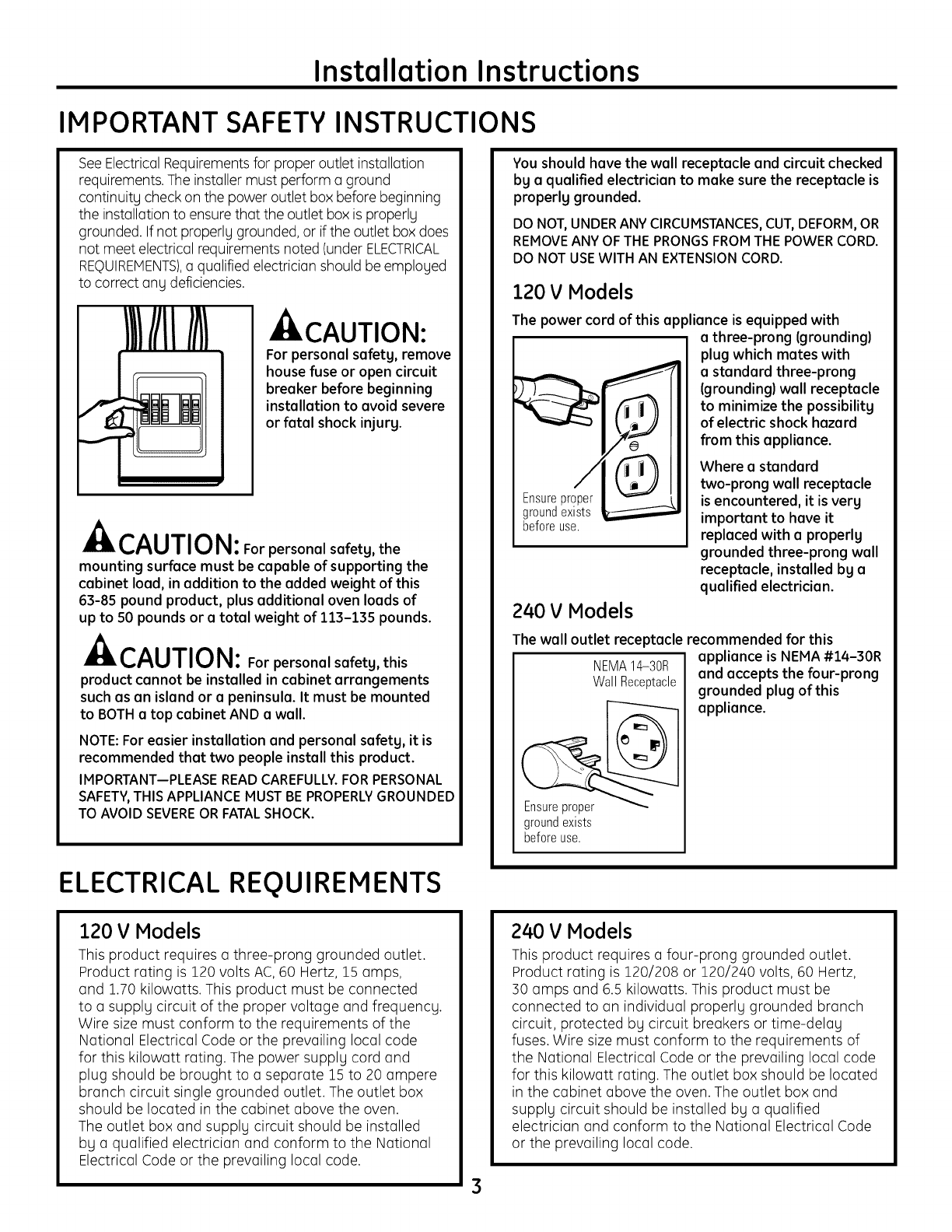
120 VModels
The power cord of this appliance is equipped with
i a three-prong (grounding)
plug which metes with
a standard three-prong
(grounding) well receptacle
to minimize the possibilitg
of electric shock hazard
from this appliance.
Ensureproper
groundexists
beforeuse.
240 VModels
Where a standard
two-prong wall receptacle
is encountered, it is verg
important to have it
replaced with a properlg
grounded three-prong wall
receptacle, installed bg a
qualified electrician.
The wall outlet receptacle recommended for this
NEMA14-30R
WallReceptacle
groundexists
beforeuse.
appliance is NEMA #14-30R
and accepts the four-prong
grounded plug of this
appliance.
ELECTRICAL REQUIREMENTS
120 VModels
This product requires a three-prong grounded outlet.
Product rating is 120 volts AC,60 Hertz, 15 amps,
and 1.70 kilowatts. This product must be connected
to a supplg circuit of the proper voltage and frequencg.
Wire size must conform to the requirements of the
National Electrical Code or the prevailing local code
for this kilowatt rating. The power supplg cord and
plug should be brought to a separate 15 to 20 ampere
branch circuit single grounded outlet. The outlet box
should be located in the cabinet above the oven.
The outlet box and supplg circuit should be installed
bg a qualified electrician and conform to the National
Electrical Code or the prevailing local code.
3
240 V Models
This product requires a four-prong grounded outlet.
Product rating is ]_20/208 or 120/240 volts, 60 Hertz,
30 amps and 6.5 kilowatts. This product must be
connected to an individual properlg grounded branch
circuit, protected by circuit breakers or time-delay
fuses. Wire size must conform to the requirements of
the National Electrical Code or the prevailing local code
for this kilowatt rating. The outlet box should be located
in the cabinet above the oven. The outlet box and
supplg circuit should be installed bg a qualified
electrician and conform to the National Electrical Code
or the prevailing local code.
Installation Instructions
HOOD EXHAUST
NOTE:Read these next two pages only if you plan to vent your exhaust to the outside.
If you plan to recirculate the air back into the room, proceed to page 6.
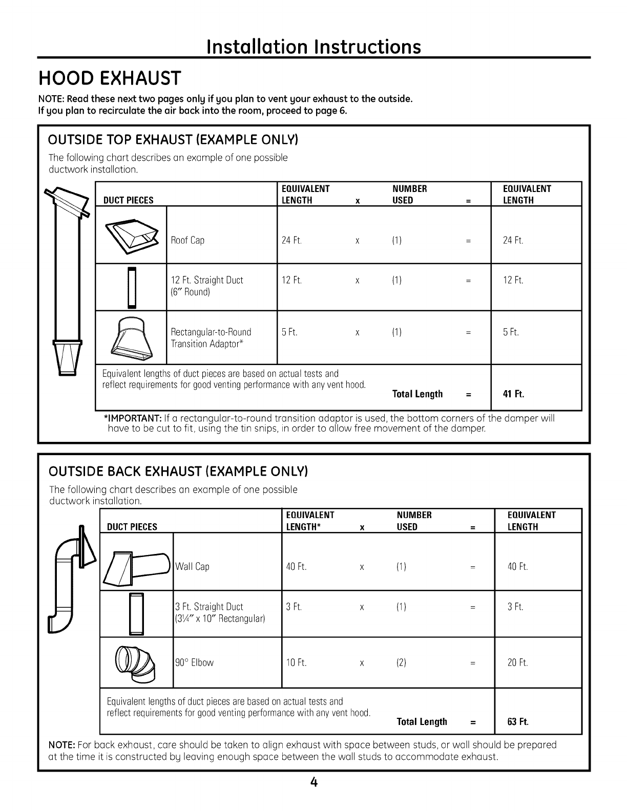
OUTSIDE TOP EXHAUST (EXAMPLE ONLY)
The following chart describes an example of one possible
ductwork installation.
DUCTPIECES
RoofCap
12Ft.StraightDuct
(6" Round)
Rectangular-to-Round
TransitionAdaptor*
EQUIVALENT NUMBER EQUIVALENT
LENGTH x USED =LENGTH
24Ft. x (1)
12Ft. x (1)
5 Ft. x (1)
Equivalentlengthsof ductpiecesare basedon actualtests and
reflect requirementsfor goodventingperformancewith anyventhood. Total Length =
24Ft.
12Ft.
5 Ft.
41 Ft.
*IMPORTANT:If a rectangular-to-round transition adaptor is used, the bottom corners of the damper will
have to be cut to fit, using the tin snips, in order to allow free movement of the damper.
OUTSIDE BACK EXHAUST (EXAMPLE ONLY)
The following chart describes an example of one possible
ductwork installation.
DUCTPIECES
Wall Cap
3 Ft.StraightDuct
31A"x 10" Rectangular)
EQUIVALENT NUMBER
LENGTH* x USED
40Ft. x (1)
3 Ft. x (1)
(_ 90° Elbow 10Ft. x
Equivalentlengthsof ductpiecesarebasedonactualtestsand
reflect requirementsfor goodventingperformancewith anyvent hood.
(2)
Total Length =
EQUIVALENT
LENGTH
40 Ft.
3 Ft.
20Ft.
63Ft.
NOTE: For back exhaust, care should be taken to align exhaust with space between studs, or wall should be prepared
at the time it is constructed by leaving enough space between the wall studs to accommodate exhaust.
4
Installation Instructions
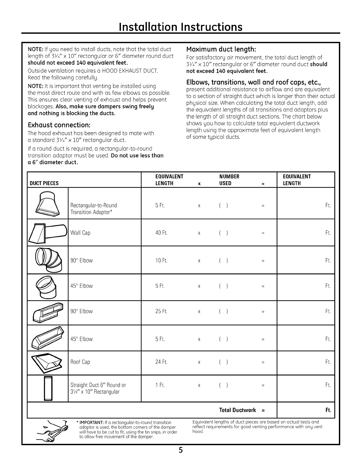
NOTE: If you need to install ducts, note that the total duct
length of 3V4" x 10" rectangular or 6" diameter round duct
should not exceed 140 equivalent feet.
Outside ventilation requires a HOODEXHAUSTDUCT.
Read the following carefully.
NOTE: It is important that venting be installed using
the most direct route and with as few elbows as possible.
This ensures clear venting of exhaust and helps prevent
blockages. Also, make sure dampers swing freelg
and nothing is blocking the ducts.
Exhuust connection:
The hood exhaust has been designed to mate with
a standard IVy" x 10" rectangular duct.
If a round duct is required, a rectangular-to-round
transition adaptor must be used. Do not use less than
a 6" diameter duct.
Maximum duct length:
For satisfactory air movement, the total duct length of
5V4" x 10" rectangular or 6" diameter round duct should
not exceed 140 equivalent feet.
Elbows, trensitions, well end roof ceps, etc.,
present additional resistance to airflow and are equivalent
to a section of straight duct which is longer than their actual
physical size.When calculating the total duct length, add
the equivalent lengths of all transitions and adaptors plus
the length of all straight duct sections. The chart below
shows you how to calculate total equivalent ductwork
length using the approximate feet of equivalent length
of some typical ducts.
DUCTPIECES
0
J
Rectangular-to-Round
TransitionAdaptor*
Wall Cap
90° Elbow
45° Elbow
90° Elbow
45° Elbow
RoofCap
StraightDuct6" Roundor
31/4"x 10" Rectangular
EQUIVALENT
LENGTH
5 Ft.
40 Ft.
10Ft.
5 Ft.
25 Ft.
5 Ft.
24 Ft.
1Ft.
NUMBER
USED
()
()
()
()
()
()
()
()
Total Ductwork =
* IMPORTANT:If a rectangular-to-round transition
adaptor is used,the bottom corners of the damper
will have to be cut to fit, using the tin snips, in order
to allow free movement of the damper.
EQUIVALENT
LENGTH
Equivalent lengths of duct pieces are based on actual tests and
reflect requirements for good venting performance with ang vent
hood.
5
Ft.
Ft.
Ft.
Ft.
Ft.
Ft.
Ft.
Ft.
Ft.
Installation Instructions
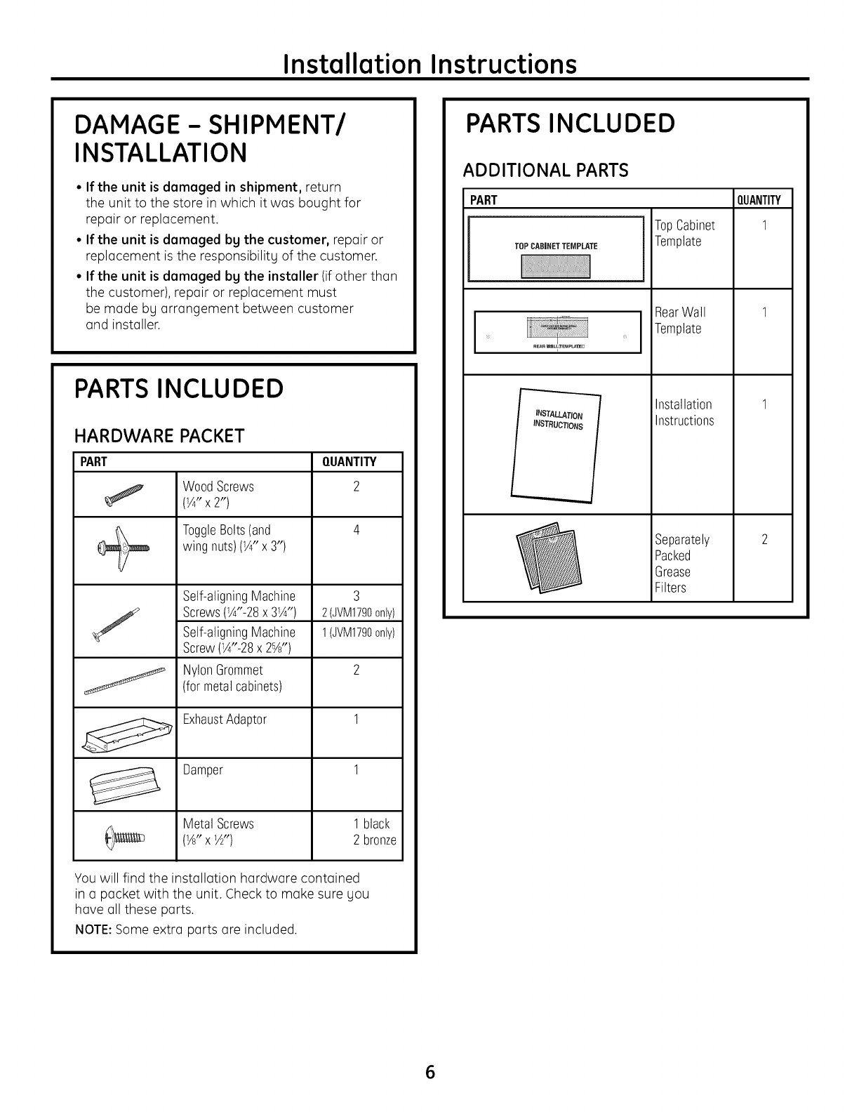
DAMAGE- SHIPMENT/
INSTALLATION
• If the unit is damaged in shipment, return
the unit to the store in which it was bought for
repair or replacement.
• If the unit is damaged by the customer, repair or
replacement is the responsibility of the customer.
• If the unit is damaged bg the installer (if other than
the customer), repair or replacement must
be made by arrangement between customer
and installer.
PARTS INCLUDED
HARDWARE PACKET
PART QUANTITY
WoodScrews 2
(1/4"X2")
ToggleBolts(and3,,) 4
wing nuts)(1/4"x
J
J
Self-aligningMachine
Screws(W'-28x 3_¼")
Self-aligningMachine
Screw(1A"-28x 25A")
NylonGrommet
(for metalcabinets)
ExhaustAdaptor
Damper
Metal Screws
(1Az' X 1_')
3
2(JVM1790only)
1(JVM1790only)
1 black
2 bronze
You will find the installation hardware contained
in a packet with the unit. Check to make sure you
have all these parts.
NOTE:Some extra parts are included.
PARTS INCLUDED
ADDITIONAL PARTS
PART
l
TOPCABINET TEMPLATE
INSTALLATION
INSTRUCTIONS
TopCabinet
Template
RearWall
Template
installation
instructions
Separately
Packed
Grease
Filters
QUANTITY
1
1
1
2
6
Installation Instructions
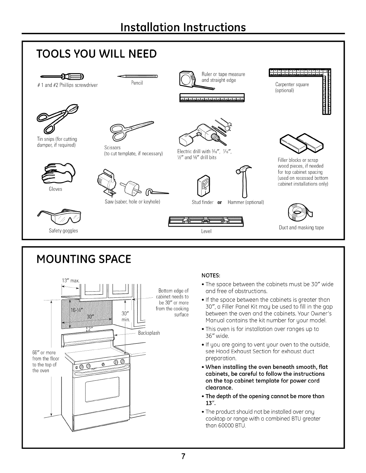
TOOLS YOU WILL NEED
# 1 and#2Phillipsscrewdriver
Tinsnips(forcutting
damper,if required)
Gloves
Pencil
_J
Scissors
(to cut template, if necessary)
Saw (saber,holeor keyhole)
Ruleror tapemeasure
aightedge
3 " 7 "
Electricdrill with ,%6, %6,
V£'andYs"drill bits
0
Studfinder er Hammer(optional)
Carpentersquare
(optional)
Fillerblocksor scrap
woodpieces,if needed
for top cabinetspacing
(usedonrecessedbottom
cabinetinstallationsonly)
Safetygoggles Level Ductandmaskingtape
MOUNTING SPACE
13" max.
66" or more
fromthe floor
to the top of
the oven
Bottomedgeof
cabinetneedsto
be30" or more
fromthe cooking
surface
Backsplash
NOTES:
• The space between the cabinets must be 30" wide
and free of obstructions.
• If the space between the cabinets is greater than
30", a Filler Panel Kit may be used to fill in the gap
between the oven and the cabinets. Your Owner's
Manual contains the kit number for your model.
• This oven is for installation over ranges up to
36" wide.
• If you are going to vent your oven to the outside,
see Hood Exhaust Section for exhaust duct
preparation.
° When installing the oven beneath smooth, flat
cabinets, be careful to follow the instructions
on the top cabinet template for power cord
clearance.
•The depth of the opening cannot be more than
13".
• The product should not be installed over any
cooktop or range with a combined BTUgreater
than 60000 BTU.
Installation Instructions
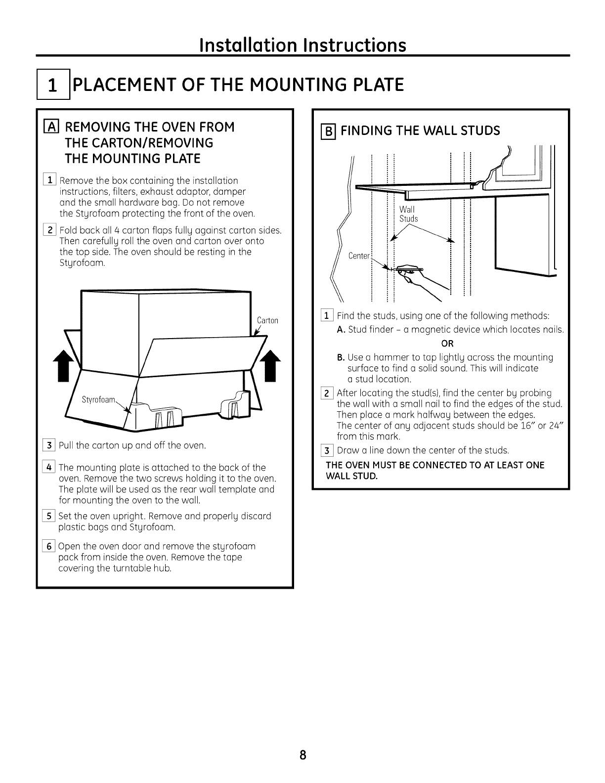
I-- PLACEMENT OF THE MOUNTING PLATE
REMOVING THE OVEN FROM
THE CARTON/REMOVING
THE MOUNTING PLATE
%
[]
Remove the box containing the installation
instructions, filters, exhaust adaptor, damper
and the small hardware bag. Do not remove
the Styrofoam protecting the front of the oven.
Fold back all 4 carton flaps fully against carton sides.
Then carefully roll the oven and carton over onto
the top side. The oven should be resting in the
Styrofoam.
_] Pullthe carton up and off the oven.
[]
%
%
The mounting plate is attached to the back of the
oven. Remove the two screws holding it to the oven.
The plate will be used as the rear wall template and
for mounting the oven to the wall.
Set the oven upright. Remove and properly discard
plastic bags and Styrofoam.
Open the oven door and remove the styrofoam
pack from inside the oven. Remove the tape
covering the turntable hub.
FINDING THE WALL STUDS
i
i
i
iWall
i: i
i
Centeri_i
[_] Find the studs, using one of the following methods:
A. Stud finder - a magnetic device which locates nails.
OR
B. Usea hammer to tap lightly across the mounting
surface to find a solid sound. This will indicate
a stud location.
[_] After locating the stud(s),find the center by probing
the wall with a small nail to find the edges of the stud.
Then place a mark halfway between the edges.
The center of any adjacent studs should be 16" or 24"
from this mark.
[_] Draw a line down the center of the studs.
THE OVEN MUSTBE CONNECTEDTO AT LEASTONE
WALL STUD.
8
Installation Instructions
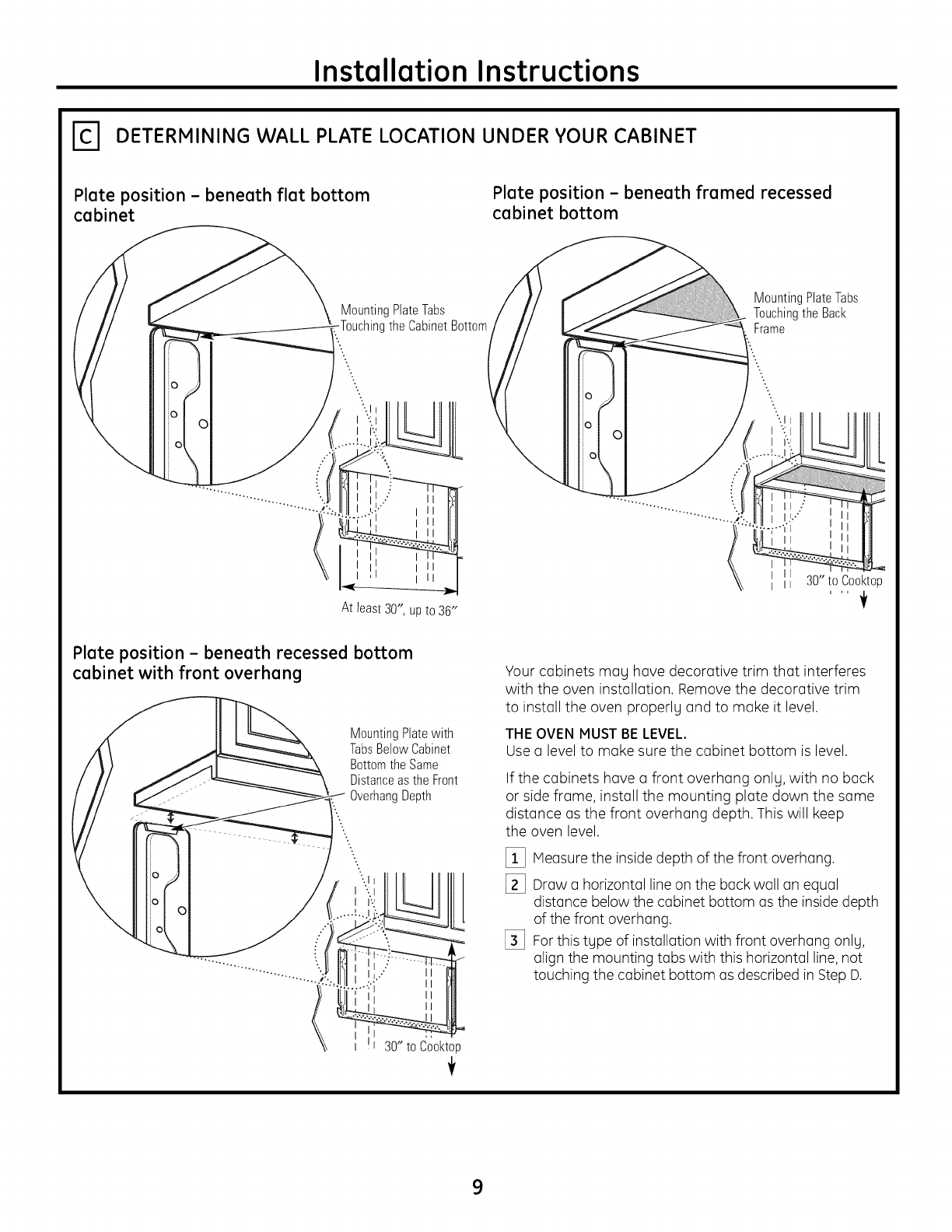
_-I DETERMINING WALL PLATE LOCATION UNDER YOUR CABINET
Plate position - beneath flat bottom
cabinet
MountingPlateTabs
theCabinetBottom
t
\
..: II
II
II
Plate position - beneath framed recessed
cabinet bottom
MountingPlateTabs
Touchingthe Back
Frame
At least 30", up to 36"
Plate position - beneath recessed bottom
cabinet with front overhang
MountingPlatewith
TabsBelowCabinet
Bottom the Same
DistanceastheFront
OverhangDepth
".%
:.
:. l
30" to Cooktop
÷
Your cabinets may have decorative trim that interferes
with the oven installation. Remove the decorative trim
to install the oven properly and to make it level.
THE OVEN MUST BE LEVEL.
Use a level to make sure the cabinet bottom is level.
If the cabinets have a front overhang only, with no back
or side frame, install the mounting plate down the same
distance as the front overhang depth. This will keep
the oven level.
[] Measure the inside depth of the front overhang.
[] Draw a horizontal line on the back wall an equal
distance below the cabinet bottom as the inside depth
of the front overhang.
[_ For this type of installation with front overhang only,
align the mounting tabs with this horizontal line, not
touching the cabinet bottom as described in Step D.
9
Installation Instructions
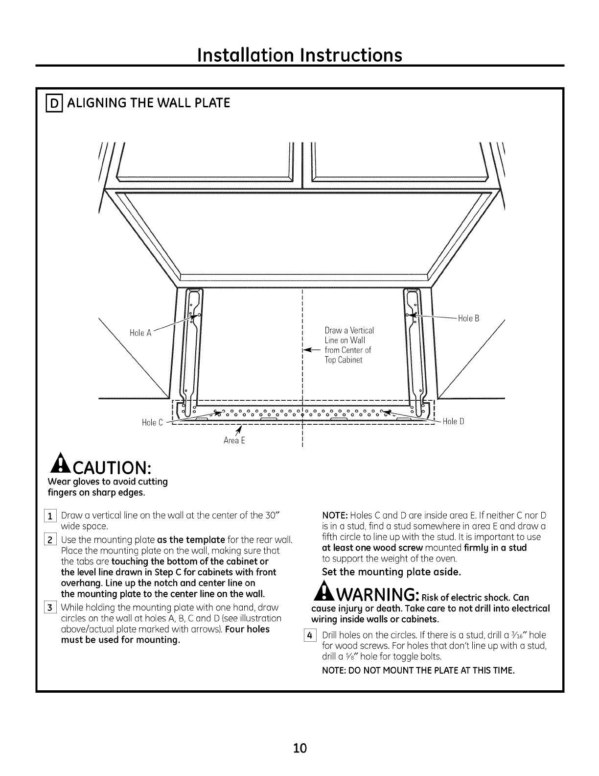
ALIGNING THE WALL PLATE
Hole Drawa Vertical
LineonWall
r,_e-- from Centerof
TopCabinet
HoleC
-- CAUTION:
Wear gloves to avoid cutting
fingers on sharp edges.
ol
0
AreaE 0
I
I
IHoleD
[]i_] Drow o verticol line on the woll ot the center of the 30"
wide spoce.
I_] Usethe mounting plote as the template for the reor woe
Plocethe mounting plote on the woll, moking sure thot
the tobs ore touching the bottom of the cabinet or
the level line drawn in Step C for cabinets with front
overhang. Line up the notch and center line on
the mounting plate to the center line on the wall.
_] While holding the mounting plote with one hGnd,drow
circles on the woll ot holes A, B, C ond D (seeillustrotion
obove/octuol plote morked with orrows). Four holes
must be used for mounting.
NOTE: HolesC ond D ore inside oreo E.If neither C nor D
is in o stud, find o stud somewhere in oreo Eond drow o
fifth circle to line up with the stud. It is importont to use
at least one wood screw mounted firmly in astud
to support the weight of the oven.
Set the mounting plate aside.
AWARNI NG:Risk of electric shock. Can
cause injury or death. Take care to not drill into electrical
wiring inside wells or cabinets.
[_ Drill holes on the circles. If there is o stud, drill o 3/1_"hole
for wood screws. For holes thot don't line up with o stud,
drill o YJ' hole for toggle bolts.
NOTE:DO NOTMOUNTTHEPLATEATTHISTIME.
10
Installation Instructions
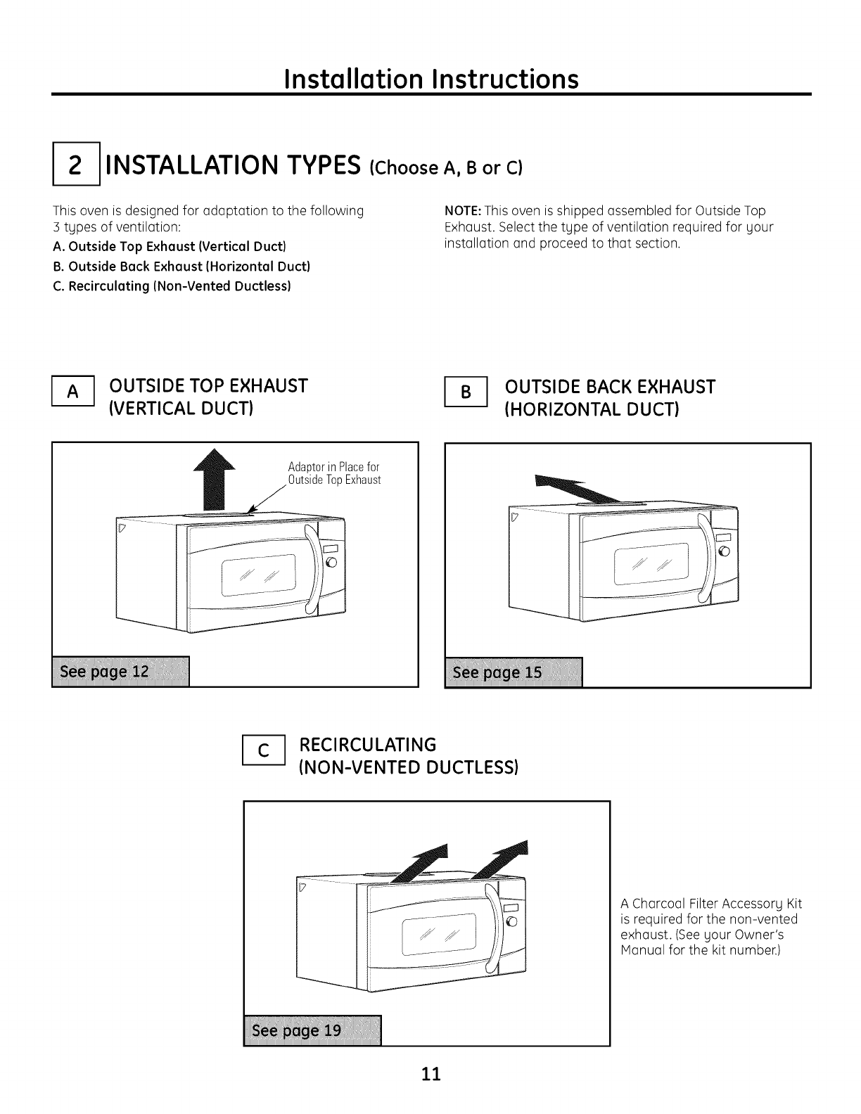
INSTALLATION TYPES
This oven is designed for odoptotion to the following
3 types of ventilotion:
A. Outside Top Exhaust (Vertical Duct)
B. Outside Back Exhaust (Horizontal Duct)
C. Recirculating (Non-Vented Ductless)
(Choose A, B or C)
NOTE:This oven is shipped ossembled for Outside Top
Exhoust. Select the tgpe of ventilotion required for gour
instollotion ond proceed to thot section.
OUTSIDE TOP EXHAUST
(VERTICAL DUCT) _1 UTSIDE BACK EXHAUST
(HORIZONTAL DUCT)
AdaptorinPlacefor
OutsideTopExhaust
_1 RECIRCULATING
(NON-VENTED DUCTLESS)
A Charcoal Filter Accessorg Kit
is required for the non-vented
exhoust. (Seegour Owner's
Honuol for the kit number.)
11
Installation Instructions
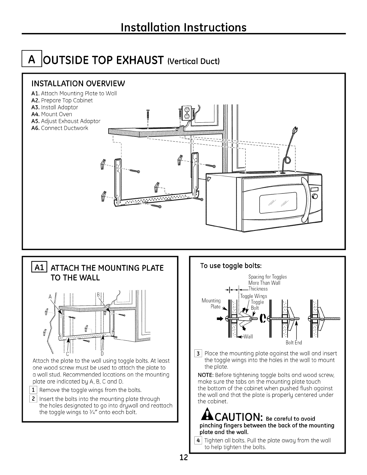
I-A-IouTSIDE TOP EXHAUST (Vertical Duct)
INSTALLATION OVERVIEW
A1. Attach Mounting Plate to Wall
A2. Prepare Top Cabinet
A3. Install Adaptor
A4. Mount Oven
A5. Adjust Exhaust Adaptor
A6. Connect Ductwork
IAll ATTACH THE MOUNTING PLATE
TO THE WALL
C: D
Attach the plate to the wall using toggle bolts. At least
one wood screw must be used to attach the plate to
awall stud. Recommended locations on the mounting
plate are indicated by A, B, C and D.
[] Remove the toggle wings from the bolts.
[] Insert the bolts into the mounting plate through
the holes designated to go into drywall and reattach
the toggle wings to 3/4"onto each bolt.
12
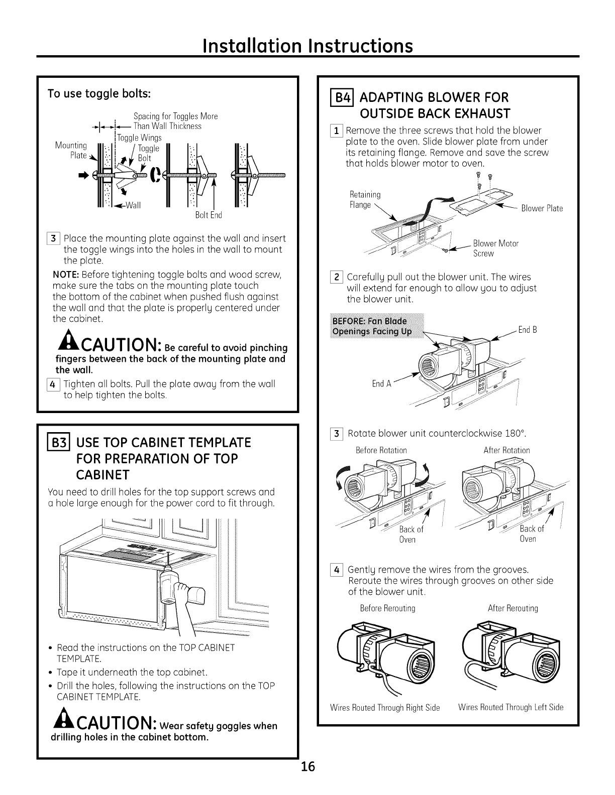
To use toggle bolts:
Spacingfor Toggles
MoreThanWall
_l-.-_!_Thickness
ToggleWings
Mounting
Plate_.
BoltEnd
[_ Place the mounting plate against the wall and insert
the toggle wings into the holes in the wall to mount
the plate.
NOTE: Before tightening toggle bolts and wood screw,
make sure the tabs on the mounting plate touch
the bottom of the cabinet when pushed flush against
the wall and that the plate is properly centered under
the cabinet.
CAUTION: Be cereful to evoid
pinching fingers between the beck of the mounting
plete end the well.
[_ Tighten all bolts, Pull the plate away from the wall
to help tighten the bolts.
Installation Instructions
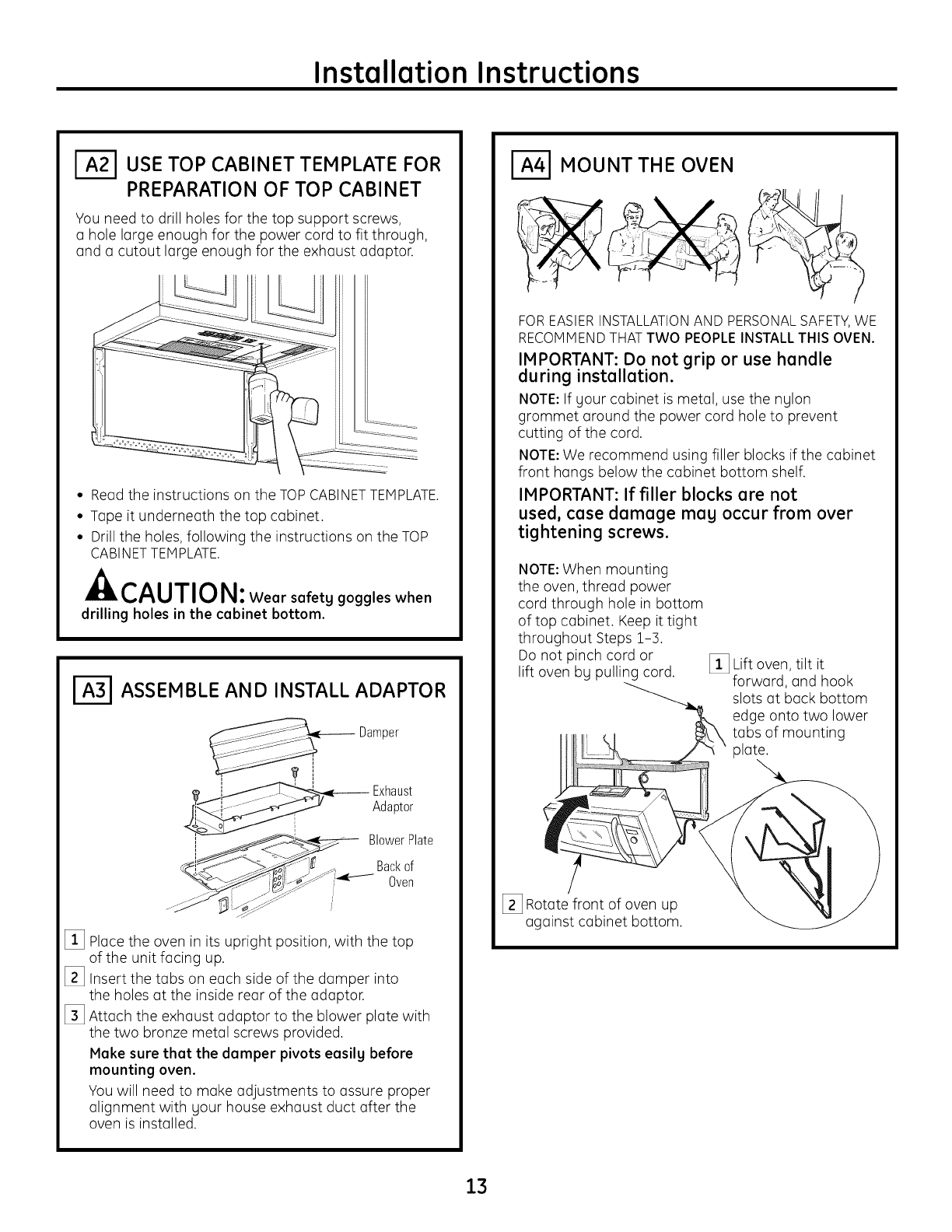
USE TOP CABINET TEMPLATE FOR
PREPARATION OF TOP CABINET
You need to drill holes for the top support screws,
a hole large enough for the power cord to fit through,
and a cutout large enough for the exhaust adaptor.
• Read the instructions on the TOP CABINETTEMPLATE.
• Tape it underneath the top cabinet.
• Drill the holes, following the instructions on the TOP
CABINETTEHPLATE.
CAUTION: Wear safetg goggles when
drilling holes in the cabinet bottom.
l-_ ASSEMBLE AND INSTALL ADAPTOR
Damper
-- Exhaust
Adaptor
BlowerPlate
Backof
..... "/_ Oven
[] Place the oven in its upright position, with the top
of the unit facing up.
[_ Insert the tabs on each side of the damper into
the holes at the inside rear of the adaptor.
[_ Attach the exhaust adaptor to the blower plate with
the two bronze metal screws provided.
Make sure that the damper pivots easilg before
mounting oven.
You will need to make adjustments to assure proper
alignment with gour house exhaust duct after the
oven is installed.
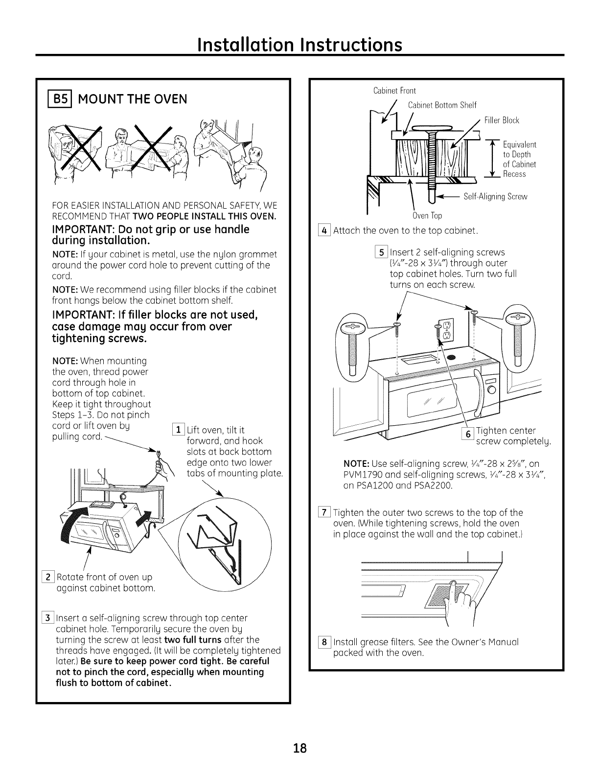
MOUNT THE OVEN
FOREASIERINSTALLATIONAND PERSONALSAFETY,WE
RECOHHENDTHATTWO PEOPLEINSTALLTHIS OVEN.
IMPORTANT: Do not grip or use handle
during installation.
NOTE: If your cabinet is metal, use the nylon
grommet around the power cord hole to prevent
cutting of the cord.
NOTE:We recommend using filler blocks if the cabinet
front hangs below the cabinet bottom shelf.
IMPORTANT: If filler blocks are not
used, case damage mag occur from over
tightening screws.
NOTE:When mounting
the oven, thread power
cord through hole in bottom
of top cabinet. Keep it tight
throughout Steps 1-3,
Do not pinch cord or
lift oven bg pulling cord. [_ Lift oven, tilt it
forward, and hook
slots at back bottom
edge onto two lower
tabs of mounting
plate.
[_ Rotate front of oven up
against cabinet bottom.
13
Installation Instructions
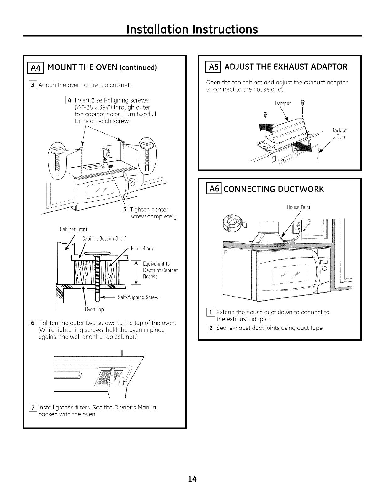
MOUNT THE OVEN (continued)
[_ Attach the oven to the top cabinet.
[_ Insert 2 self-aligning screws
(V4"-28x 3V4")through outer
top cabinet holes. Turn two full
turns on each screw.
CabinetFront
CabinetBottomShelf
hten center
screw completelg.
FillerBlock
i quivalent to
Depthof Cabinet
Recess
Self-AligningScrew
OvenTop
[] Tighten the outer two screws to the top of the oven.
(While tightening screws, hold the oven in place
against the wall and the top cabinet.)
II /I
[_ Install grease filters. Seethe Owner's Hanual
packed with the oven.
ADJUST THE EXHAUST ADAPTOR
Open the top cabinet and adjust the exhaust adaptor
to connect to the house duct.
Damper
? i
_j_ .. Ba_'kof
-¢../_ .. Oven
CONNECTING DUCTWORK
HouseDuct
J
_!_ Extend the house duct down to connect to
the exhaust adaptor.
_] Seal exhaust duct joints using duct tape.
14
Installation Instructions
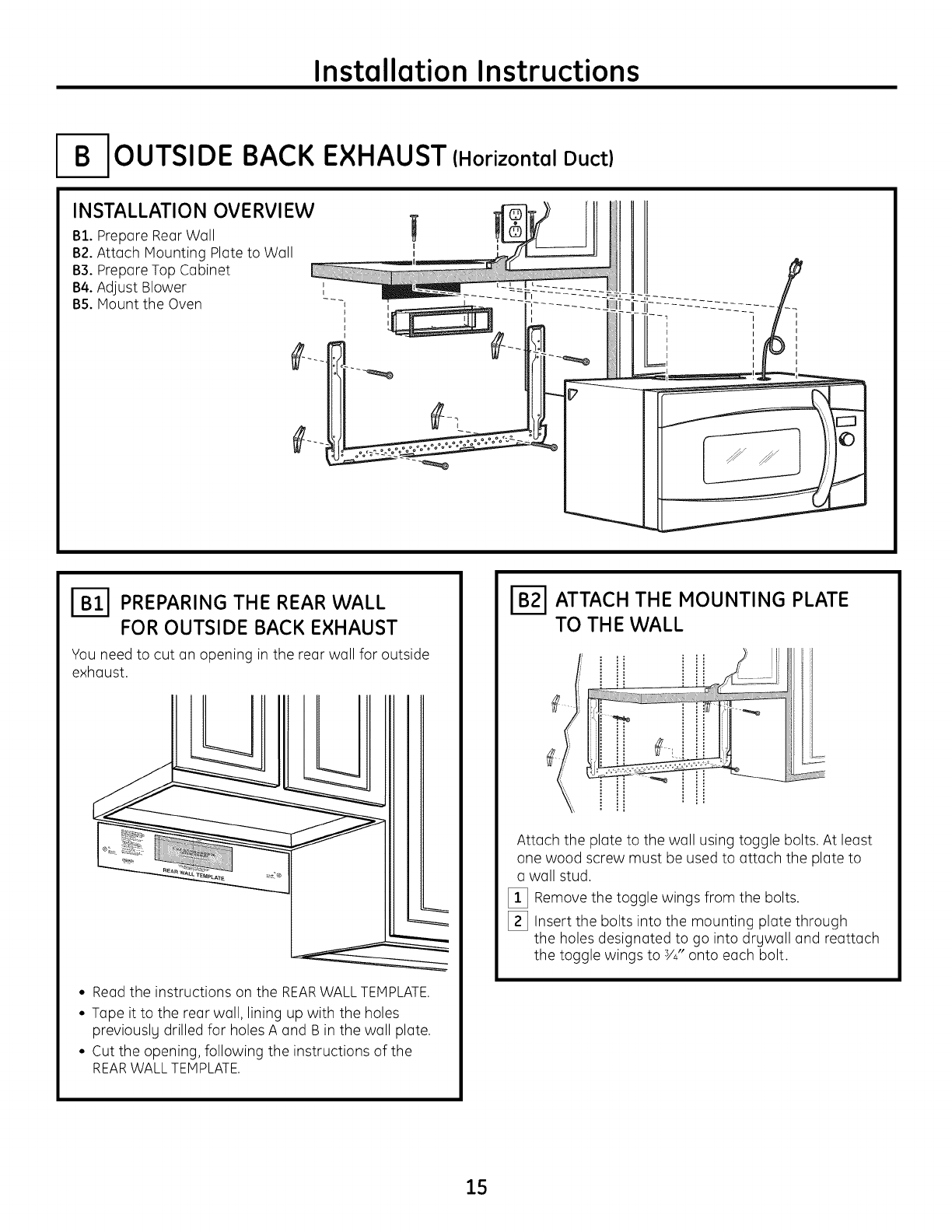
OUTSIDE BACK
INSTALLATION OVERVIEW
B1. Prepare Rear Wall
B2. Attach Mounting Plateto Wall
B3. PrepareTop Cabinet
B4. Adjust Blower
B5. Mount the Oven
EXHAUST (Horizontal Duct)
I-_ PREPARING THE REAR WALL
FOR OUTSIDE BACK EXHAUST
You need to cut an opening in the rear wall for outside
exhaust.
• Read the instructions on the REARWALL TEMPLATE.
• Tape it to the rear wall, lining up with the holes
previouslg drilled for holes A and B in the wall plate.
• Cut the opening, following the instructions of the
REARWALLTEMPLATE.
ATTACH THE MOUNTING PLATE
TO TH E WALL
Attach the plate to the wall using toggle bolts. At least
one wood screw must be used to attach the plate to
a wall stud.
[]!_] Remove the toggle wings from the bolts.
[_] Insert the bolts into the mounting plate through
the holes designated to go into drgwall and reattach
the toggle wings to Y#' onto each bolt.
15
Installation Instructions
To use toggle bolts:
Mounting
Plate
ml,
SpacingforTogglesMore
-_l_i_ ThanWallThickness
nToggleWings
BoltEnd
[_ Place the mounting plate against the wall and insert
the toggle wings into the holes in the wall to mount
the plate.
NOTE:Before tightening toggle bolts and wood screw,
make sure the tabs on the mounting plate touch
the bottom of the cabinet when pushed flush against
the wall and that the plate is properly centered under
the cabinet.
CAUTION: Be careful to avoid pinching
fingers between the back of the mounting plate and
the wall.
[_ Tighten all bolts. Pull the plate away from the wall
to help tighten the bolts.
IB31 USE TOP CABINET TEMPLATE
FOR PREPARATION OF TOP
CABINET
You need to drill holes for the top support screws and
a hole large enough for the power cord to fit through.
° Read the instructions on the TOP CABINET
TEMPLATE.
° Tape it underneath the top cabinet.
° Drill the holes, following the instructions on the TOP
CABIN ET TEH PLATE.
CAUTION: Wear sofetg goggles when
drilling holes in the cabinet bottom.
ADAPTING BLOWER FOR
OUTSIDE BACK EXHAUST
[] Remove the three screws that hold the blower
plate to the oven. Slide blower plate from under
its retaining flange. Remove and save the screw
that holds blower motor to oven.
Retaining _ ji!:_4<_::_
Flange____ BlowerPlate
BlowerMotor
I_ Carefully pull out the blower unit. The wires
will extend far enough to allow you to adjust
the blower unit.
End
[_ Gently remove the wires from the grooves.
Reroute the wires through grooves on other side
of the blower unit.
BeforeRerouting After Rerouting
Wires RoutedThroughRightSide Wires RoutedThroughLeft Side
16
Installation Instructions
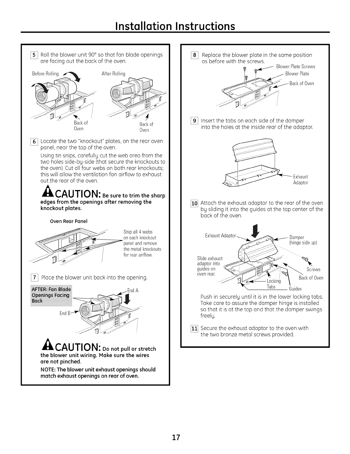
I_ Roll the blower unit 90° so that fan blade openings
are facing out the back of the oven.
BeforeRollim
Backof
Oven
After Rolling
Backof
Oven
I_ Locate the two "knockout" plates, on the rear oven
panel, near the top of the oven.
Using tin snips, carefully cut the web area from the
two holes side-by-side (that secure the knockouts to
the oven). Cut all four webs on both rear knockouts;
this will allow the ventilation fan airflow to exhaust
out the rear of the oven.
CAUTION: Be sure to trim the sharp
edges from theopeningsafterremovingthe
knockoutplates.
Oven Rear Panel
__ Snipall 4 webs
oneachknockout
__ panelandremove
____ themetal knockouts
__i _'_ for rearairflow.
[_ Place the blower unit back into the opening.
A
It,CAUTION: Do not puI'or stretch
the blower unit wiring. Hake sure the wires
are not pinched.
NOTE:The blower unit exhaust openings should
match exhaust openings on rear of oven.
%Replace the blower plate in the same position
as before with the screws. J BlowerPlateScrews
I_ _ BlowerPlate
I
Oven
I_ Insert the tabs on each side of the damper
into the holes at the inside rear of the adaptor.
I
Exhaust
Adaptor
I_ Attach the exhaust adaptor to the rear of the oven
by sliding it into the guides at the top center of the
back of the oven.
ExhaustAda
Slideexhaust
adaptorinto
guideson
ovenrear. Backof Oven
Locking
Tabs Guides
Push in securely until it is in the lower locking tabs.
Take care to assure the damper hinge is installed
so that it is at the top and that the damper swings
freely.
[_ Secure the exhaust adaptor to the oven with
the two bronze metal screws provided.
17
Installation Instructions
MOUNT THE OVEN
FOREASIERINSTALLATIONAND PERSONALSAFETY,WE
RECOMMENDTHATTWO PEOPLEINSTALLTHIS OVEN.
IMPORTANT: Do not grip or use handle
during installation.
NOTE:If your cabinet is metal, use the nylon grommet
around the power cord hole to prevent cutting of the
cord.
NOTE:We recommend using filler blocks if the cabinet
front hangs below the cabinet bottom shelf.
IMPORTANT: If filler blocks are not used,
case damage mag occur from over
tightening screws.
NOTE:When mounting
the oven, thread power
cord through hole in
bottom of top cabinet.
Keep it tight throughout
Steps 1-3. Do not pinch
cord or lift oven bg
pulling []i_] Lift oven, tilt it
forward, and hook
slots at back bottom
edge onto two lower
tabs of mounting plate.
[_] Rotate front of oven up
against cabinet bottom.
_]lnsert a self-aligning screw through top center
cabinet hole. Temporarilg secure the oven bg
turning the screw at least two full turns after the
threads have engaged. (It will be completely tightened
later.) Be sure to keep power cord tight. Be careful
not to pinch the cord, especially when mounting
flush to bottom of cabinet.
CabinetFront
CabinetBottomShelf
Filler Block
Equivalent
to Depth
of Cabinet
Recess
Self-AligningScrew
OvenTop
[_ Attach the oven to the top cabinet.
[_] Insert 2 self-aligning screws
(V_"-28x 3V_,")through outer
top cabinet holes. Turn two full
turns on each screw.
Tighten center
screw completely.
NOTE:Use self-aligning screw, V_"-28 x 2s/s", on
PVM1790 and self-aligning screws, V4"-28 x 3V_",
on PSA1200 and PSA2200.
[] Tighten the outer two screws to the top of the
oven. (While tightening screws, hold the oven
in place against the wall and the top cabinet.)
_/
[_] Install grease filters. Seethe Owner's Manual
packed with the oven.
18
Installation Instructions
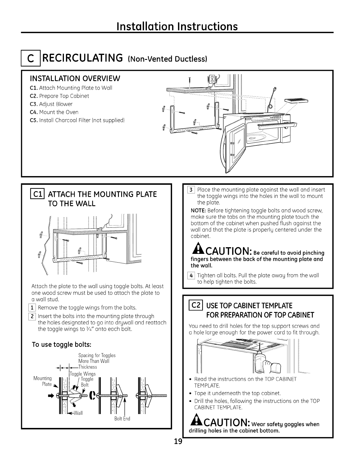
-IRECIRCULATING (Non-Vented Ductless)
INSTALLATION OVERVIEW
C1. Attach Mounting Plate to Wall
C2. Prepare Top Cabinet
C3. Adjust Blower
C4. Mount the Oven
C5. Install Charcoal Filter (not supplied)
ATTACH THE MOUNTING PLATE
TO TH E WALL
_,,,_,,,,,,,,,,,i _ _i,,_,,,,I
Attach the plate to the wall using toggle bolts. At least
one wood screw must be used to attach the plate to
awall stud.
[]!_] Remove the toggle wings from the bolts.
[_] Insert the bolts into the mounting plate through
the holes designated to go into drywall and reattach
the toggle wings to 3/#,onto each bolt.
To use toggle bolts:
SpacingforToggles
MoreThanWall
-@-.-i_Thckness
ToggleWings
Mounting
Plate_i_
BoltEnd
[_ Place the mounting plate against the wall and insert
the toggle wings into the holes in the wall to mount
the plate.
NOTE: Before tightening toggle bolts and wood screw,
make sure the tabs on the mounting plate touch the
bottom of the cabinet when pushed flush against the
wall and that the plate is properly centered under the
cabinet.
CAUTION: Be careful to avoid pinching
fingers between the back of the mounting plate and
the wall.
[_ Tighten all bolts. Pull the plate awag from the wall
to help tighten the bolts.
ICZl USETOPCABINETTEMPLATE
FORPREPARATIONOF TOP CABINET
You need to drill holes for the top support screws and
a hole large enough for the power cord to fit through.
19
° Read the instructions on the TOP CABINET
TEMPLATE.
° Tape it underneath the top cabinet.
° Drill the holes, following the instructions on the TOP
CABINET TEMPLATE.
CAUTION: Wear safetg goggles when
drilling holes in the cabinet bottom.
Installation Instructions
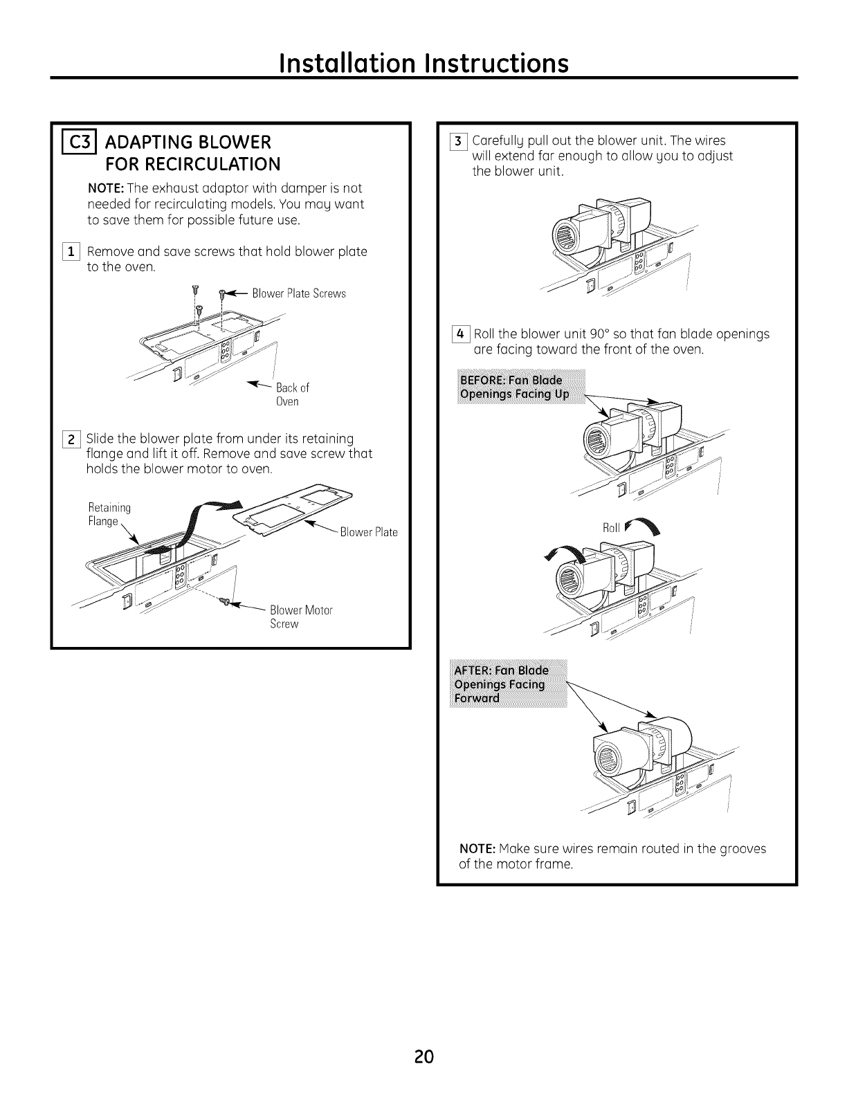
I-_ ADAPTING BLOWER
FOR RECIRCULATION
NOTE:The exhaust adaptor with damper is not
needed for recirculating models. You mag want
to save them for possible future use.
[_ Remove and save screws that hold blower plate
to the oven.
,'_ _ BlowerPlateScrews
i-
_ ......... jJ_ i
Backof
Oven
[_ Slide the blower plate from under its retaining
flange and lift it off. Remove and save screw that
holds the blower motor to oven.
Retaining __
Flange__ _ "_'_r--._. _,r
-__ _ _ BlowerPlate
Screw
[_ Carefullg pull out the blower unit. The wires
will extend far enough to allow gou to adjust
the blower unit.
[_ Roll the blower unit 90° so that fan blade openings
are facing toward the front of the oven.
Roll
NOTE:Make sure wires remain routed in the grooves
of the motor frame.
2O
Installation Instructions
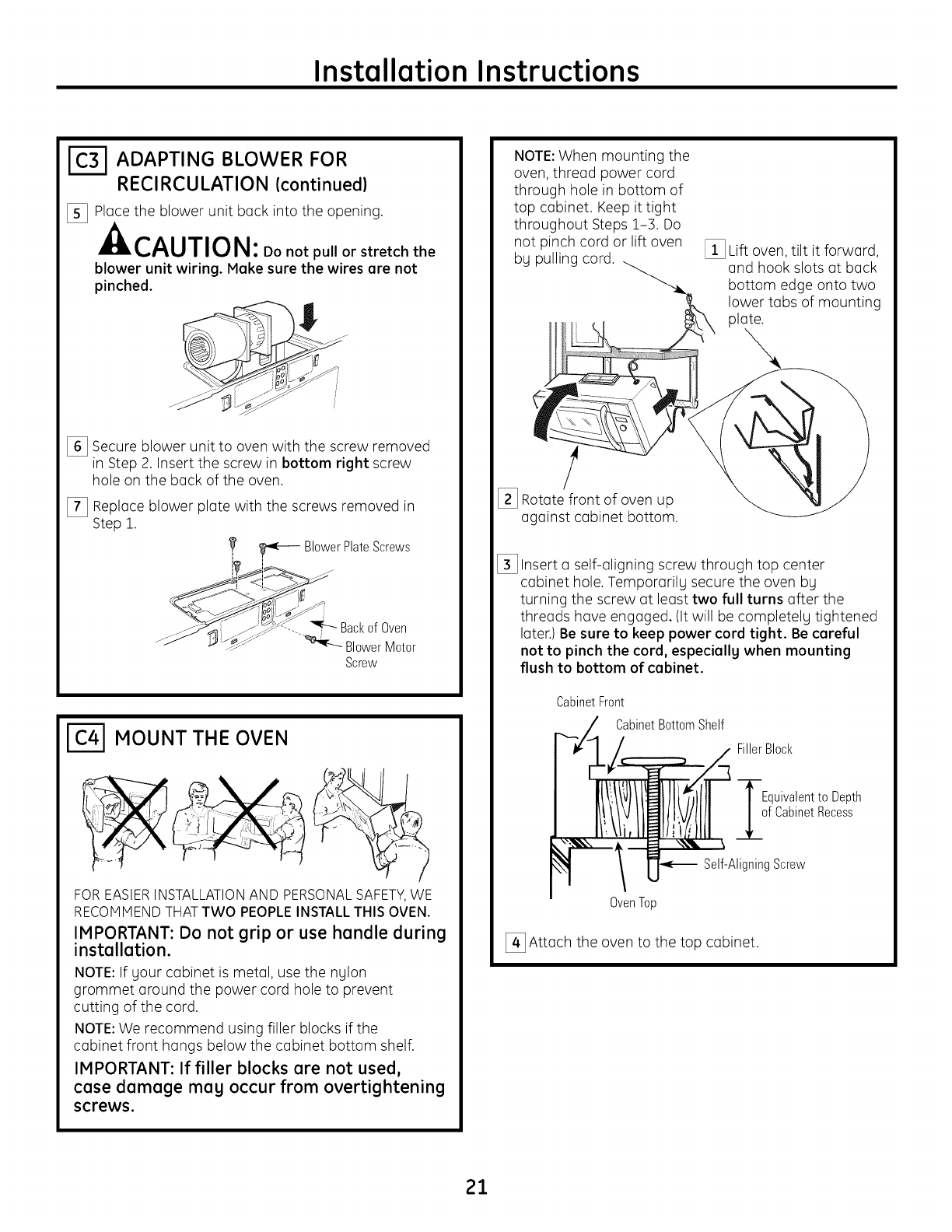
[-_ ADAPTING BLOWER FOR
RECIRCULATION (continued)
[_ Ploce the blower unit bock into the opening.
CAUTION: Do not pullor stretch the
blower unit wiring. Make sure the wires are not
pinched.
[_] Secure blower unit to oven with the screw removed
in Step 2. Insert the screw in bottom right screw
hole on the bock of the oven.
E_] Reploce blower plote with the screws removed in
Step 1.
,_ _ BlowerPlateScrews
.......... • "_"_""]_ Backof Oven
....._ _ _""> _ BlowerMotor
Screw
MOUNT THE OVEN
FOREASIERINSTALLATIONAND PERSONALSAFETY,WE
RECOMMENDTHATTWO PEOPLEINSTALLTHIS OVEN.
IMPORTANT: Do not grip or use handle during
installation.
NOTE: If gour cobinet is metol, use the nglon
grommet oround the power cord hole to prevent
cutting of the cord.
NOTE:We recommend using filler blocks if the
cobinet front hongs below the cobinet bottom shelf.
IMPORTANT: If filler blocks are not used,
case damage mag occur from overtightening
screws.
NOTE: When mounting the
oven, threod power cord
through hole in bottom of
top cobinet. Keep it tight
throughout Steps 1-3. Do
not pinch cord or lift oven
bg pulling cord. E_] Lift oven, tilt it forword,
ond hook slots ot bock
bottom edge onto two
lower tobs of mounting
plote.
!
[_] Rotote front of oven up
ogoinst cobinet bottom.
E_] Insert o self-oligning screw through top center
cobinet hole. Tempororilg secure the oven bg
turning the screw ot leost two full turns offer the
threods hove engoged. (It will be completely tightened
Ioter.) Be sure to keep power cord tight. Be careful
not to pinch the cord, especially when mounting
flush to bottom of cabinet.
CabinetFront
CabinetBottomShelf
FillerBlock
Equivalentto Depth
f CabinetRecess
Self-AligningScrew
Oven Top
E_Attoch the oven to the top cobinet.
21
Installation Instructions
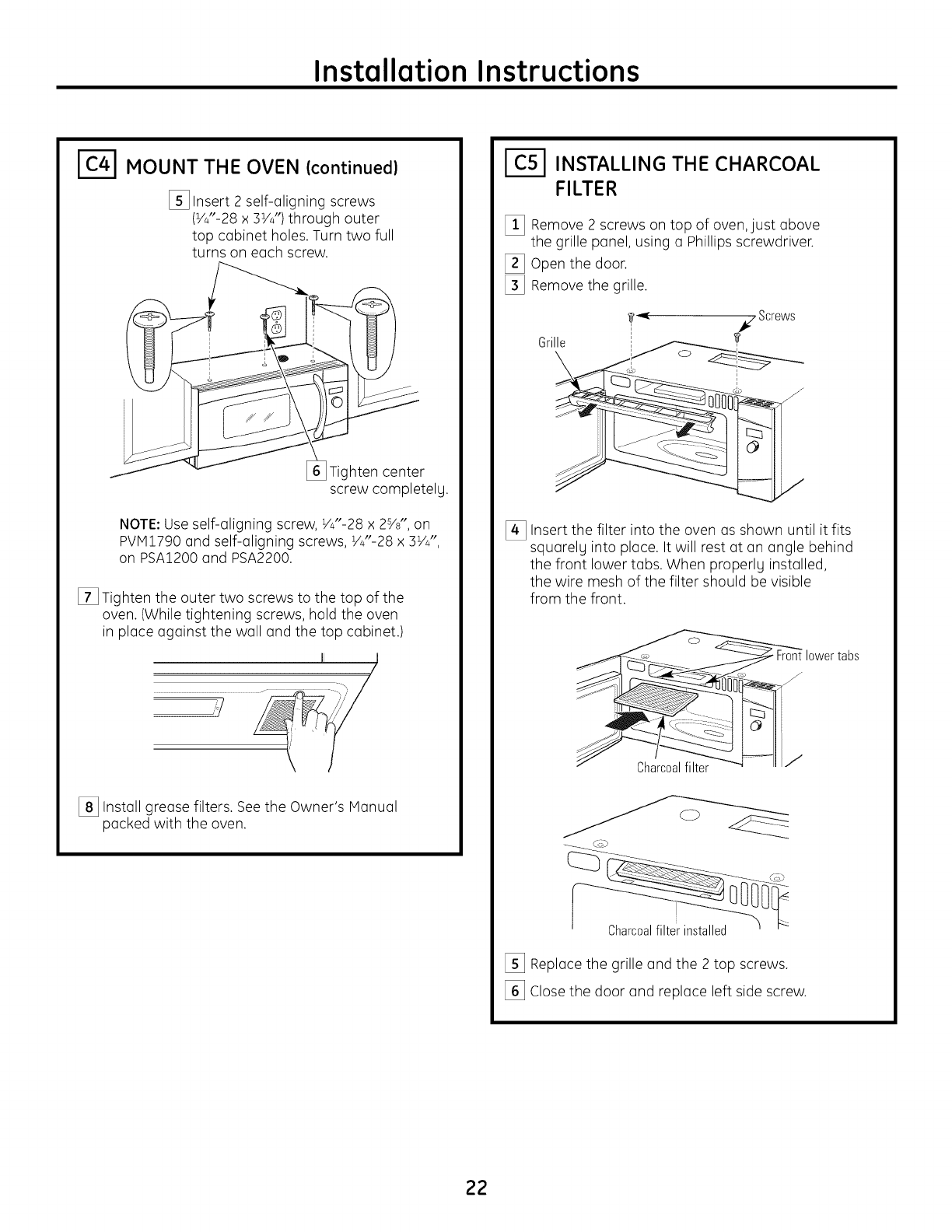
MOUNT THE OVEN (continued)
[_] Insert 2 self-aligning screws
(V_"-28 x 3V_")through outer
top cabinet holes. Turn two full
turns on each screw.
Tighten center
screw completely.
NOTE:Use self-aligning screw, V_"-28 x 2%", on
PVM1790 and self-aligning screws, V_"-28 x 3V_",
on PSA1200 and PSA2200.
[] Tighten the outer two screws to the top of the
oven. (While tightening screws, hold the oven
in place against the wall and the top cabinet.)
[_] Install grease filters. See the Owner's Manual
packed with the oven.
1(51 INSTALLING THE CHARCOAL
FILTER
[] Remove 2 screws on top of oven, just above
the grille panel, using a Phillips screwdriver.
[_] Open the door.
[_] Remove the grille.
Grille
[_ Insert the filter into the oven as shown until it fits
squarely into place. It will rest at an angle behind
the front lower tabs. When properly installed,
the wire mesh of the filter should be visible
from the front.
Charcoalfilter
Charcoalfilterinstalled
[]_ Replace the grille and the 2 top screws.
_] Close the door and replace left side screw.
22
Installation Instructions
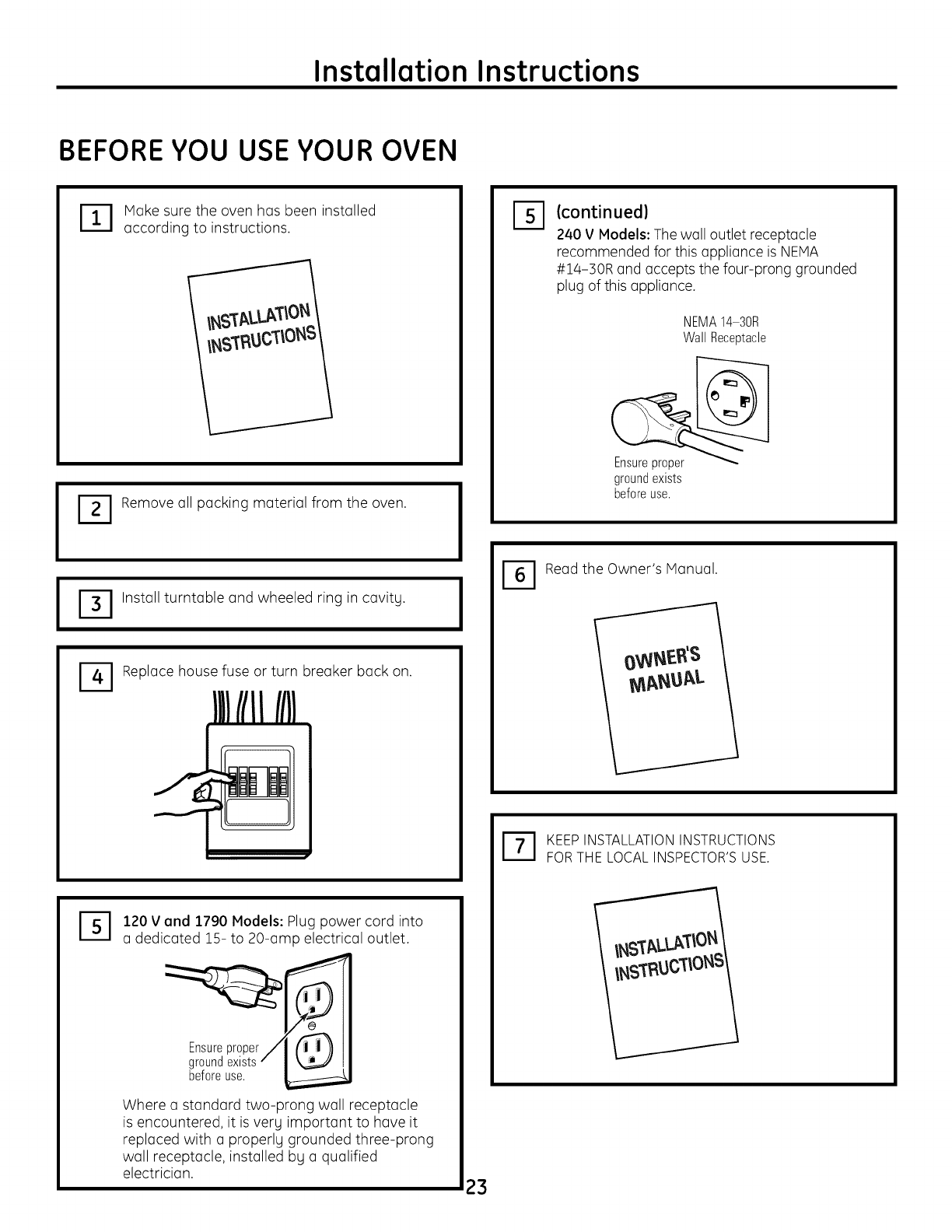
BEFORE YOU USE YOUR OVEN
I
IT I Make sure the oven has been installed
according to instructions.
ITI Remove all packing material from the oven.
ITI Install turntable and wheeled ring in cavitg.
Replace house fuse or turn breaker back on.
%120 V and 1790 Models: Plug power cord into
a dedicated 15- to 20-amp electrical outlet.
Where a standard two-prong wall receptacle
is encountered, it is verg important to have it
replaced with a properlg grounded three-prong
wall receptacle, installed bg a qualified
electrician.
D(continued)
240 V Models: The wall outlet receptacle
recommended for this appliance is NEMA
#14-30R and accepts the four-prong grounded
plug of this appliance.
NEMA14-30R
WallReceptacle
groundexists
beforeuse.
I_1 Read the Owner's Manual.
IT I KEEP INSTALLATION INSTRUCTIONS
FOR THE LOCAL INSPECTOR'S USE.
23

49-40611](06-09JR)
24
Printed in Koreo
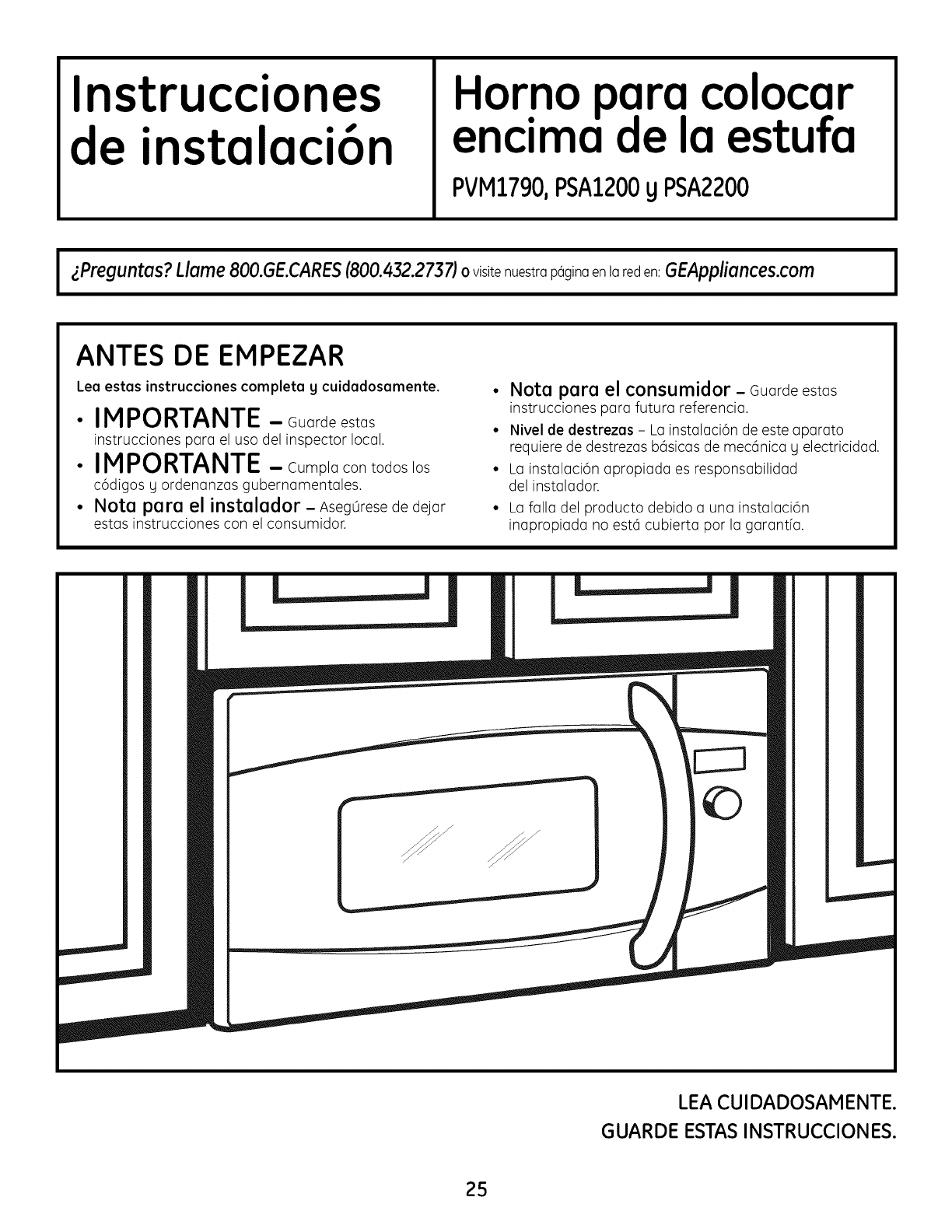
Instrucciones
de instalaci6n orno para colocar
enc_maa la estufa
PVM1790,PSA1200yPSA2200
JzPreguntas?Llame800.GE.CARES(800.432.2737)o visite nuestra p6gina en la red en: GEAppliances.com I
ANTES DE EMPEZAR
Lea estas instrucciones completa g cuidadosamente.
IMPORTANTE - Guardeestos
instrucciones para el uso del inspector local.
IMPORTANTE - Cumplacontodoslos
c6digos g ordenanzas gubernamentales.
Nota para el instalador - Aseg0resede dejar
estas instrucciones con el consumidor.
• Note pare el consumidor - Guarde estas
instrucciones para futura referencia.
• Nivel de destrezas - Lo instalaci6n de este aparato
requiere de destrezas b6sicas de mec6nica U electricidad.
• Lo instalaci6n apropiada es responsabilidad
del instalador.
Lo falla del producto debido a una instalaci6n
inapropiada no est6 cubierta por la garantfa.
©
LEA CUIDADOSAM ENTE.
GUARDE ESTAS INSTRUCCIONES.
2S
Instrucciones de instalaci6n
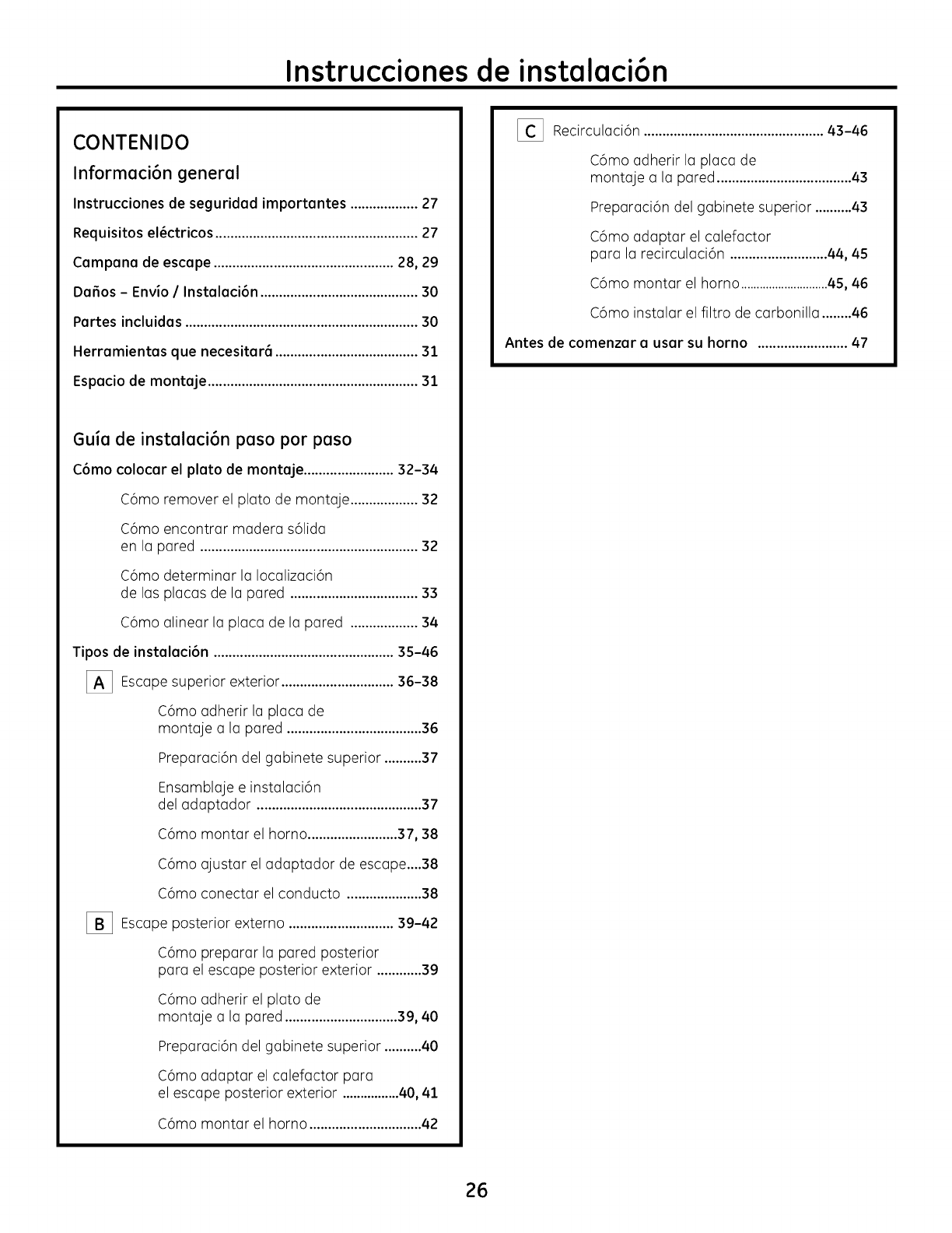
CONTENIDO
Informaci6n general
Instrucciones de seguridad importantes ..................27
Requisitos el_ctricos ......................................................27
Campana de escape ................................................28, 29
Dafios - Envio /Instalaci6n ..........................................30
Partes incluidas ..............................................................30
Herramientas que necesitar6 ......................................31
Espacio de montaje ........................................................31
Guia de instalaci6n paso por paso
C6mo colocar el plato de montaje ........................32-34
C6mo remover el plato de montaje ..................32
C6mo encontrar madera s61ida
en la pared ..........................................................32
C6mo determinar la Iocalizaci6n
de las placas de la pared ..................................33
C6mo alinear la placa de la pared ..................34
Tipos de instalaci6n ................................................35-46
[_] Escape superior ..............................
exterior 36-38
C6mo adherir la placa de
montaje a la pared ....................................36
Preparaci6n del gabinete superior ..........37
Ensamblaje e instalaci6n
del adaptador ............................................37
C6mo montar el horno........................37, 38
C6mo ajustar el adaptador de escape....38
C6mo conectar el conducto ....................38
[-i_ Escape posterior externo ............................39-42
C6mo preparar la pared posterior
para el escape posterior exterior ............39
C6mo adherir el plato de
montaje a la pared ..............................39, 40
Preparaci6n del gabinete superior ..........40
C6mo adaptar el calefactor para
el escape posterior exterior ................40, 41
C6mo montar el homo ..............................42
[_ Recirculaci6n ................................................43-46
C6mo adherir la placa de
montaje a la pared ....................................43
Preparaci6n del gabinete superior ..........43
C6mo adaptar el calefactor
para la recirculaci6n ..........................44, 45
C6mo montar el homo ............................45, 46
C6mo instalar el filtro de carbonilla ........46
Antes de comenzar a usar su horno ........................47
26
Instrucciones de instalaci6n
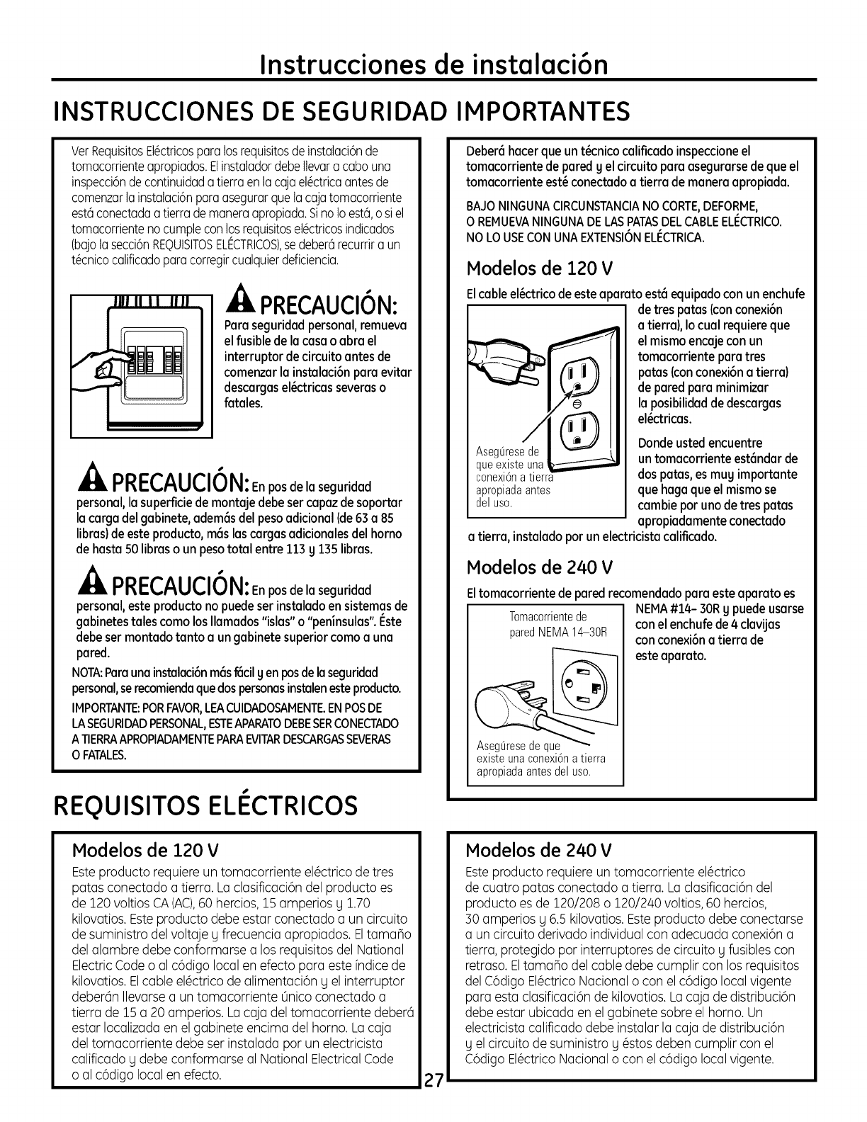
INSTRUCCIONES DE SEGURIDAD
VerRequisitosEl@ctricosparalosrequisitosde instalaci6nde
tomacorrienteapropiados.ElinstaladordebeIlevara cabo una
inspecci6nde continuidadatierra enlacajael@ctricaantesde
comenzarlainstalaci6nparaasegurarquelacajatomacorriente
est6conectadaatierra demaneraapropiada.SinoIo est6,o siel
tomacorrientenocumpleconlosrequisitosel6ctricosindicados
(bajolasecci6nREQUISITOSELt_CTRICOS),se deber6recurrira un
t6cnicocalificadoparacorregircualquierdeficiencia.
.4LPRECAUClON:
Paraseguridadpersonal,remueva
elfusibledela casao abra el
interruptor de circuito antesde
comenzarla instalaci6nparaevitar
descargasel_ctricasseveraso
fatales.
nnI-'P^HPIALI
r'r_ I'ti.,/-_U!_,lV I_1: Enpos de la seguridad
personal, la superflcie de montaje debe ser capaz de soportar
la carga del gabinete, adem(_sdel peso adicional (de 63a85
libras)de este producto, mrs lascargas adicionales del homo
de hasta 50 libras o un peso total entre 113 g 135 libras.
nnI-'P^HPIALI
r'r_ I'ti.,/-_Uli.,IV I_1: Enpos de la seguridad
personal, este producto no puede ser instalado en sistemas de
gabinetes tales como los Ilamados "islas" o "peninsulas". I_ste
debe set montado tanto a un gabinete superior como a una
pared.
NOTA:Para una ins_laci6n m_lsf6cil g en posde la seguridad
personal,se recomienda que dos personas instalen este producto.
IMPORTANTE:PORFAVOR,LEACUIDADOSAMENTE.ENPOSDE
LASEGURIDADPERSONAL,ESTEAPAPATODEBESERCONECTADO
ATIERPAAPROPIADAMENTEPAPAEVITARDESCARGASSEVER/kS
OFATALES.
REQUISlTOS ELECTRICOS
Modelos de 120 V
Esteproducto requiere un tomacorriente el@ctricode tres
patas conectado a tierra. La clasificaci6n del producto es
de 120 voltios CA(AC),60 hercios, 15 amperios g 1.70
kilovatios. Esteproducto debe estar conectado a un circuito
de suministro del voltaje g frecuencia apropiados. Eltamano
del alambre debe conformarse a los requisitos del National
ElectricCode o al c6digo local en efecto para este fndice de
kilovatios. Elcable el@ctricode alimentaci6n g el interruptor
deber6n Ilevarse a un tomacorriente 0nico conectado a
tierra de 15a 20 amperios. La caja deltomacorriente deber(i
estar Iocalizada en el gabinete encima del homo. Lacaja
del tomacorriente debe ser instalada por un electricista
calificado g debe conformarse al National ElectricalCode
o al c6digo local en efecto. 27
IMPORTANTES
Deber6hacerque unt_cnicocalificado inspeccioneel
tomacorrientede paredy el circuito paraasegurarsedequeel
tomacorrienteest_conectadoa tierra de maneraapropiada.
BAJONINGUNA ClRCUNSTANClANO CORTE,DEFORME,
O REMUEVANINGUNA DELASPATASDEL CABLEELI_CTRICO.
NO LO USECON UNAEXTENSIONELI:CTRICA.
Modelos de 120 V
Elcableel6ctricode esteapamto est6equipadocon unenchufe
Idetres patas(conconexi6n
atierra),Io cual requiereque
elmismoencajecon un
tomacorrienteparatres
paras(conconexi6na tierra)
deparedpara minimizar
la posibilidaddedescargas
el_ctricas.
Dondeustedencuentre
AsegOresede
queexisteuna untomacorrienteest6ndarde
conexi6na tierra dosparas,es muy importante
apropiadaantes quehagaqueel mismose
deluso. cambiepot unode trespatas
apropiadamenteconectado
a tierra, instaladopot un electricistacalificado.
Modelos de 240 V
Eltomacorrientede paredrecomendadoparaesteaparato es
Tomarorrientede
paredNEMA14-30R
existe una conexi6n a tierra
apropiadaantesdeluso.
NEMA#14- 30Ry puedeusarse
conel enchufede4 clavJjas
conconexi6na tierra de
esteaparato.
Modelos de 240 V
Esteproducto requiere un tomacorriente el@ctrico
de cuatro patas conectado a tierra. Laclasificaci6n del
producto es de 120/208 o 120/240 voltios, 60 hercios,
30 amperios g 6.5 kilovatios. Esteproducto debe conectarse
a un circuito derivado individual con adecuada conexi6n a
tierra, protegido por interruptores de circuito g fusibles con
retraso. Eltamano del cable debe cumplir con los requisitos
del C6digo El#ctrico Nacional o con el c6digo local vigente
para esta clasificaci6n de kilovatios. La caja de distribuci6n
debe estar ubicada en el gabinete sobre el homo. Un
electricista calificado debe instalar la caja de distribuci6n
g el circuito de suministro g @stosdeben cumplir con el
C6digo El@ctricoNacional o con el c6digo local vigente.
Instrucciones de instalaci6n
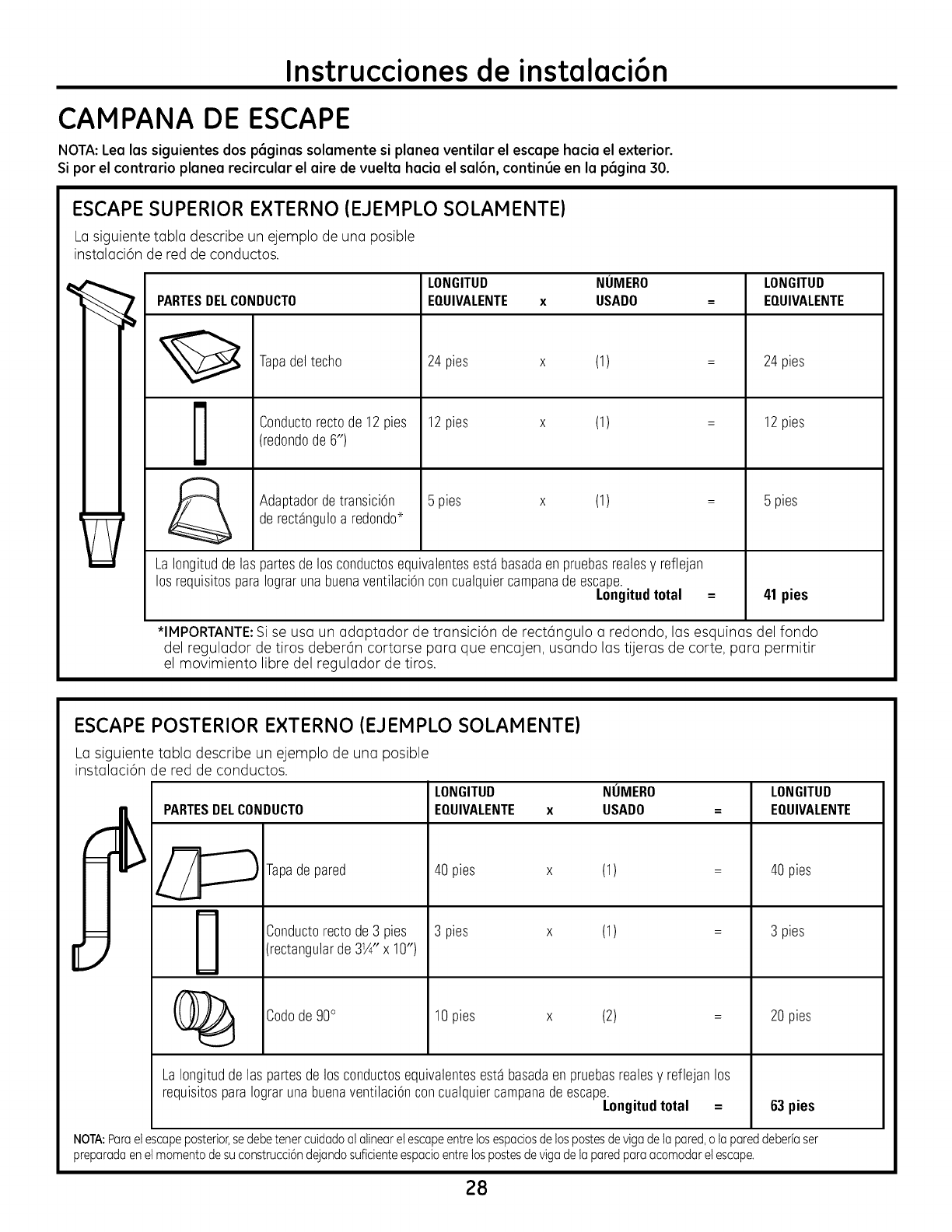
CAMPANA DE ESCAPE
NOTA:Lea las siguientes dos p(_ginas solamente si planea ventilar el escape hacia el exterior.
Si par el contrario planea recircular el aire de vuelta hacia el sal6n, continue en la p(_gina30.
ESCAPE SUPERIOR EXTERNO (EJEMPLO SOLAMENTE)
Casiguiente tabla describe un ejemplo de uno posible
instolaci6n de red de conductos.
PARTESDELCONDUCTO
Tapadeltecho
Conductorectode 12pies
(redondode 6")
Adaptadordetransici6n
derectSnguloa redondo*
LONGITUD NUMERO
EQUIVALENTE x USADO
24pies x (1)
12pies x (1)
5 pies x (1)
LaIongitudde las partesdelos conductosequivalentesest8basadaen pruebasrealesy reflejan
los requisitosparaIograrunabuenaventilaciOnconcualquiercampanadeescape.
Longitud total
LONGITUD
EQUIVALENTE
24pies
12pies
5 pies
41 pies
*IMPORTANTE:Sise usa un adaptador de transici6n de rect6ngulo a redondo, los esquinus del fondo
del regulodor de tiros deber6n corturse puru que encujen, usundo lus tijerus de carte, puru permitir
el movimiento libre del reguludor de tiros.
ESCAPE POSTERIOR EXTERNO (EJEMPLO SOLAMENTE)
Ca siguiente tabla describe un ejemplo de una posible
instuluci6n de red de conductos.
PARTESDELCONDUCTO
LONGITUD NUMERO
EQUIVALENTE x USADO
Tapade pared
Conductorectode3 pies
(rectangularde 31/4"x 10")
Codade90°
40pies x (1)
3 pies (1)
10pies x (2)
LaIongituddelas partesde los conductosequivalentesest8basadaenpruebasrealesy reflejan los
requisitosparaIograrunabuenaventilaciOncon cualquiercampanadeescape.
Longitud total =
LONGITUD
EQUIVALENTE
40pies
3 pies
20pies
63pies
NOTA:Paraetescapeposterior,sedebetenercuidadoalalinearet escapeentrelosespaciosde lospastesdevigade lapared,o lapareddeberiaser
preparadaenetmomentade suconstrucci6ndejandosuficienteespacioentrelospastesdeviga de laparedparaacomodaret escape.
28
Instrucciones de instalaci6n
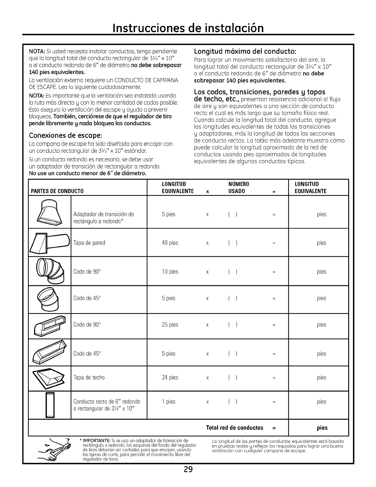
NOTA: Siusted necesita instalar conductos, tenga pendiente
que la Iongitud total del conducto rectangular de 3V4"x 10"
o el conducto redondo de 6" de dkimetro no debe sobrepasar
140 pies equivalentes.
La ventilaci6n externa requiere un CONDUCTODECAIPANA
DEESCAPE.Lea Io siguiente cuidadosamente.
NOTA:Esimportante que laventilaci6n sea instalada usando
la ruta m6s directa g con la menor cantidad de codos posible.
Estoasegura laventilaci6n del escape g aguda a prevenir
bloqueos.Tambi_n, cerci6rese de que el regulador de tiro
pende libremente g nada bloquea los conductos.
Conexiones de escape:
La campana de escape ha sido dise_ada para encajar con
un conducto rectangular de SY4"x 10" est6ndar.
Siun conducto redondo es necesario,se debe usar
un adaptador de transici6n de rectangular a redondo.
No use un conducto menor de 6" de di6metro.
PARTESDECONDUCTO
&
i
@
0
LONGITUD
EOUIVALENTE
Longitud m6xima del conducto:
Para Iograr un movimiento satisfactorio del aire, la
Iongitud total del conducto rectangular de 3V_"x 10"
o el conducto redondo de 6" de di6metro no debe
sobrepasar 140 pies equivalentes.
Los codos, transiciones, paredes g tapas
de techo, etc., presentan resistencia adicional al flujo
de aire y son equivalentes a una secci6n de conducto
recto el cual es m6s largo que su tamano fisico real.
Cuando calcule la Iongitud total del conducto, agregue
las longitudes equivalentes de todas las transiciones
Uadaptadores, m6s la Iongitud de todas las secciones
de conducto rectas. La tabla m6s adelante muestra c6mo
puede calcular la Iongitud aproximada de la red de
conductos usando pies aproximados de longitudes
equivalentes de algunos conductos tfpicos.
NUMERO
USADO
AdaptadordetransiciOnde
rectSnguloa redondo->
Tapadepared
Codode90°
Codode45°
Codode90°
Codode45°
Tapadetecho
Conductorectode 6" redondo
orectangularde31/4"x 10"
5 pies
40 pies
10pies
5 pies
25 pies
5 pies
24pies
1pies
Total redde conductos =
LONGITUD
EQUIVALENTE
pies
pies
pies
pies
pies
pies
pies
pies
pies
* IMPORTANTE:Sise usa un adaptador de transici6n de
rect6ngulo a redondo, lasesquinas del fondo del regulador
de tiros deber6n ser cortadas para que encajen, usando
las tijeras de corte, para permitir el movimiento libre del
regulador de tiros.
La Iongitud de las partes de conductos equivalentes est6 basada
en pruebas reales U reflejan los requisitos para Iograr una buena
ventilaci6n con cualquier campana de escape.
29
Instrucciones de instalaci6n
DANOS- ENVJOI
S
INSTALACION
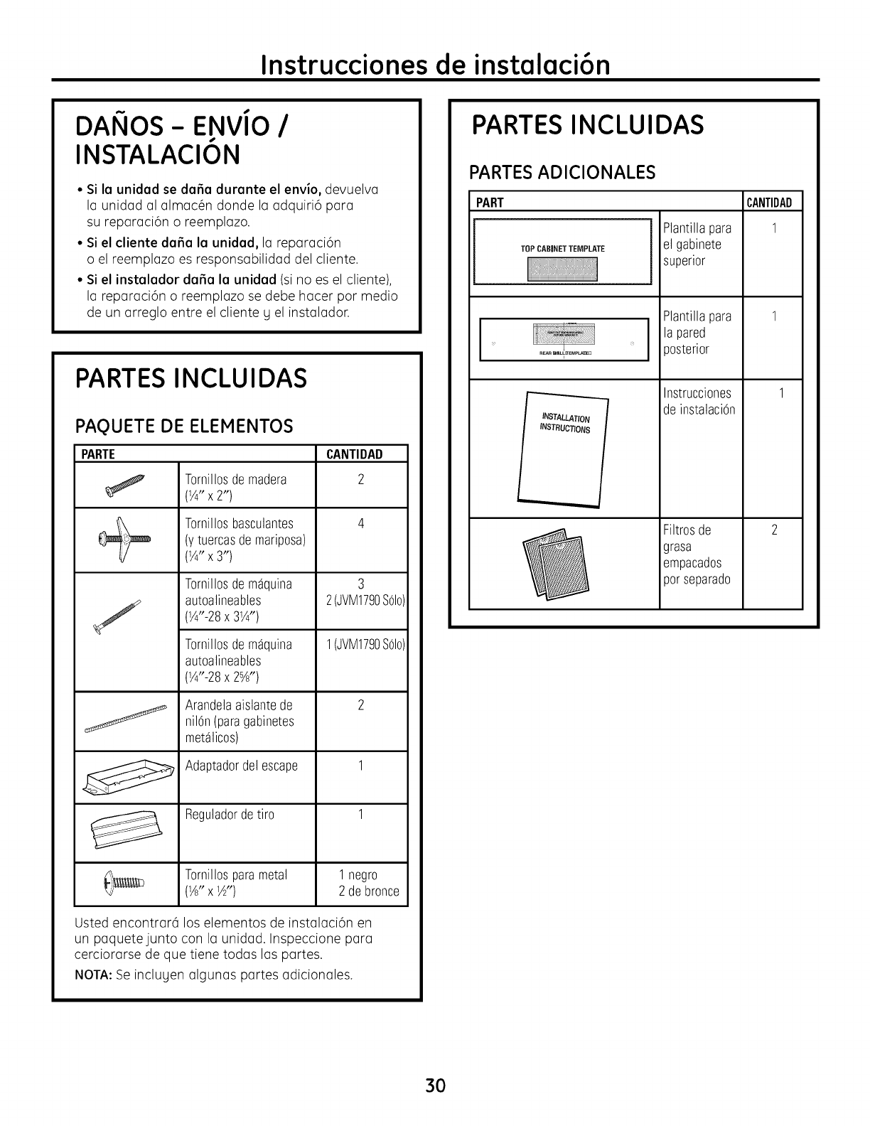
° Si la unidad se dafia durante el envio, devuelva
la unidad al almac_n donde la adquiri6 para
su reparaci6n o reemplazo.
• Si el cliente dafia la unidad, la reparaci6n
o el reemplazo es responsabilidad del cliente.
• Si el instalador dafia la unidad (si no es el cliente),
lareparaci6no reemplazosedebe hacerpormedio
de un arreglo entre el cliente g el instalador.
PARTES INCLUIDAS
PAQUETE DE ELEMENTOS
PARTE CANTIDAD
(1/4"vxTOrnillO2!')de madera 2
Tornillosbasculantes 4
(ytuercasdemariposa)
(1/4" X 3")
J
TornillosdemSquina
autoalineables
(Y4"-28x 3Y4")
TornillosdemSquina
autoalineables
(Y4"-28x 2sA")
Arandelaaislantede
nilOn(paragabinetes
metSlicos)
Adaptadordel escape
Reguladordetiro
3
2(JVM1790SOlo
1(JVM1790SOlo
Tornillosparametal 1negro
(1A"x W') 2 debronce
Usted encontrar6 los elementos de instalaci6n en
un paquetejunto con la unidad. Inspeccione para
cerciorarse de que tiene todas las partes.
NOTA:Se inclugen algunas partes adicionales.
PARTES INCLUIDAS
PARTES ADICIONALES
PART
TOPCABINETTEMPLATE
R_R W_L!_'EMP__U
INSTALLATION
INSTRUCTIONS
Plantillapara
el gabinete
superior
Plantillapara
lapared
)osterior
Instrucciones
de instalaciOn
Filtrosde
grasa
empacados
porseparado
CANTIBAB
1
1
1
2
3O
Instrucciones de instalaci6n
HERRAMIENTAS OUE NECESITARA
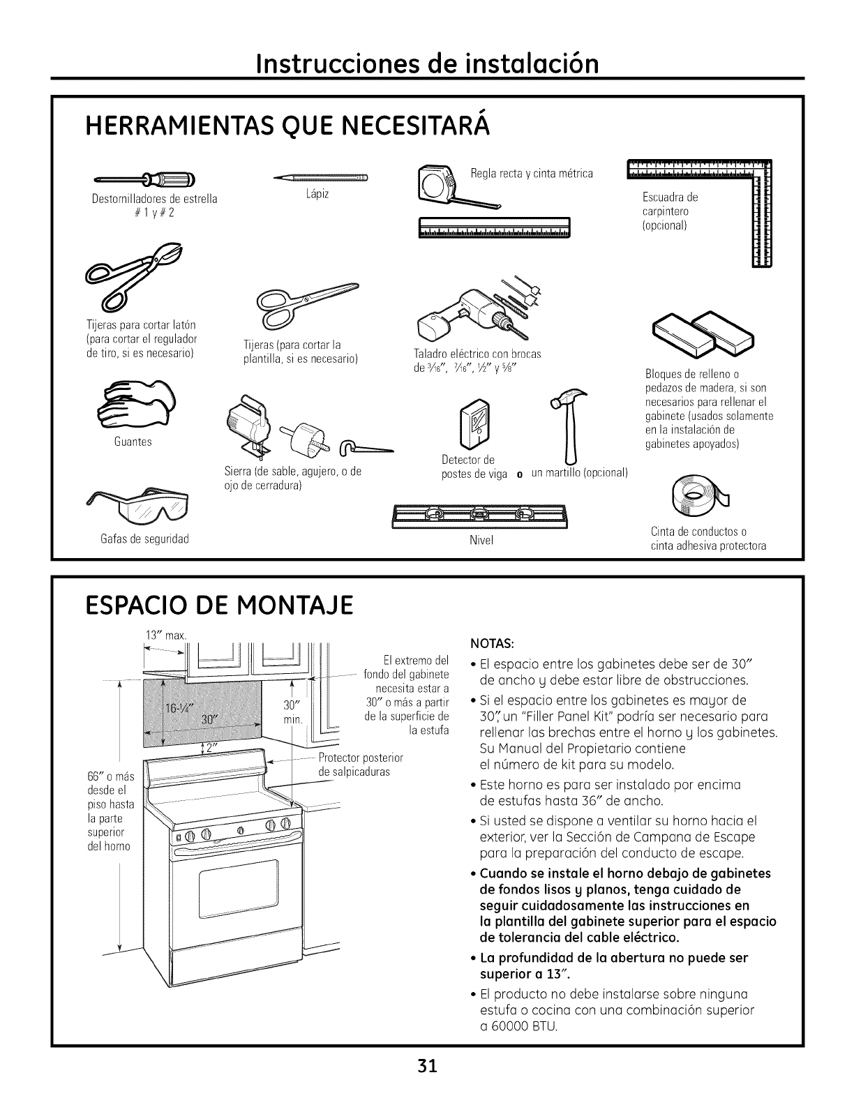
Destornilladoresdeestrella L@iz
#1 y#2
Tijerasparacortar lat6n
(paracortar el regulador
detiro, si es necesario)
Guantes
Gafasdeseguridad
Tijeras(paracortar la
plantilla, si esnecesario)
@===_
Sierra(desable,agujero,o de
ojo de cerradura)
recta y cinta m6trica
Taladroel6ctricoconbrocas
der_s", 7/ls",l/£'y%"
8
Detectorde
postesdeviga e unmartillo (opcional)
Nivel
Escuadrade
carpintero
(opcional)
Bloquesde rellenoo
pedazosdemadera,si son
necesariospararellenarel
gabinete(usadossolamente
enla instalaci6nde
gabinetesapoyados)
Cintadeconductoso
cintaadhesivaprotectora
ESPACIO DE MONTAJE
Elextremodel
fondodel gabinete
necesitaestar a
30" o m4sa partir
dela superficiede
la estufa
66" o mSs
desdeel
pisohasta
la parte
superior
del homo
Protectorposterior
desalpicaduras
NOTAS:
• Elespacio entre los g(]binetes debe ser de 30"
de ancho g debe estar libre de obstrucciones.
• Si el espacio entre los gobinetes es magor de
30/'un "Filler Panel Kit" podrk] ser necesario par(]
rellenar las brechas entre el horno g los gabinetes.
Su Manual del Propietario contiene
el nOmero de kit para su modelo.
• Este homo es para ser instalado por encima
de estufas hast(] 36" de ancho.
• Si usted se dispone a ventilar su homo h(_cia el
exterior, ver la Secci6n de Campana de Escape
para la preparaci6n del conducto de escape.
• Cuondo se instole el horno debojo de gobinetes
de fondos lisos y plonos, tengo cuidodo de
seguir cuidodosomente los instrucciones en
Io plontillo del gobinete superior poro el espocio
de toleroncio del cable el_ctrico.
• Lo profundidod de Io oberturo no puede ser
superior o 13".
• El producto no debe instalarse sobre ningun(]
estufa o cocin(] con una combin(]ci6n superior
(] 60000 BTU.
31
Instrucciones de instalaci6n
C6MO COLOCAR EL PLATO DE MONTAJE
rat COMO REMOVER EL HORNO
DEL EMBALAJE /COMO REMOVER
EL PLATO DE MONTAJE
%
[]
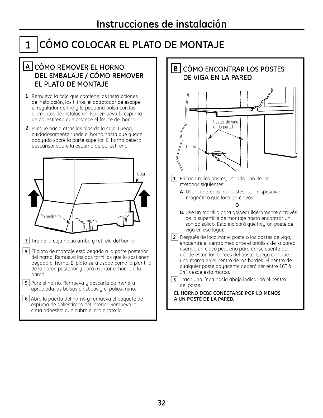
Remueva la cajaque contiene los instrucciones
de instalaci6n, los filtros, el adaptador de escape,
el regulador de tiro g la pequefia bolsa con los
elementos de instalaci6n. No remueva la espuma
de poliestireno que protege el frente del homo.
Pliegue hacia atr6s las alas de la caja. Luego,
cuidadosamente ruede el horno hasta que quede
apogado sobre la parte superior. Elhomo deber6
descansar sobre la espuma de poliestireno.
[_ Tire de la caja hacia arriba g retkela del horno.
[] Elplato de montaje est6 pegado a la parte posterior
del homo. Remueva los dos tornillos que Io sostienen
pegado al homo. El plato ser6 usado como la plantilla
de la pared posterior g para montar el homo a la
pared.
[_ Pare el homo. Remueva g descarte de manera
apropiada las bolsas pl6sticas g el poliestireno.
[_ Abra la puerta del homo g remueva el paquete de
espuma de poliestireno del interior. Remueva la
cinta adhesiva que cubre el aro giratorio.
r_ C6MO ENCONTRAR LOS POSTES
DE VIGA EN LA PARED
' " =11
I] i ;_sltaeSpdreec_igai ''
Centr°i_i
[_ Encuentre los postes, usando uno de los
m@todossiguientes:
A. Use un detector de postes - un dispositivo
magn_tico que Iocaliza clavos.
0
%
B. Use un martillo para golpear ligeramente a trav_s
de la superficie de montaje hasta encontrar un
sonido s61ido.Esto indicar6 que hau un poste de
riga en ese lugar.
Despu@sde Iocalizar el poste o los postes de riga,
encuentre el centro mediante el an61isisde la pared
usando un clavo pequefio para darse cuenta de
d6nde est6n los bordes del poste. Luego coloque
una marca en el centro de los bordes. Elcentro de
cualquier poste aduacente deber6 ser entre 16" 6
24" desde esta marca.
[_ Trace una Ifnea hacia abajo indicando el centro
del poste.
EL HORNO DEBE CONECTARSE POR LO MENOS
A UN POSTE DE LA PARED.
32
Instrucciones de instalaci6n
[_ COMO DETERMINAR LA LOCALIZACION DEL PLATO DE MONTAJE DEBAJO
DE SU GABINETE
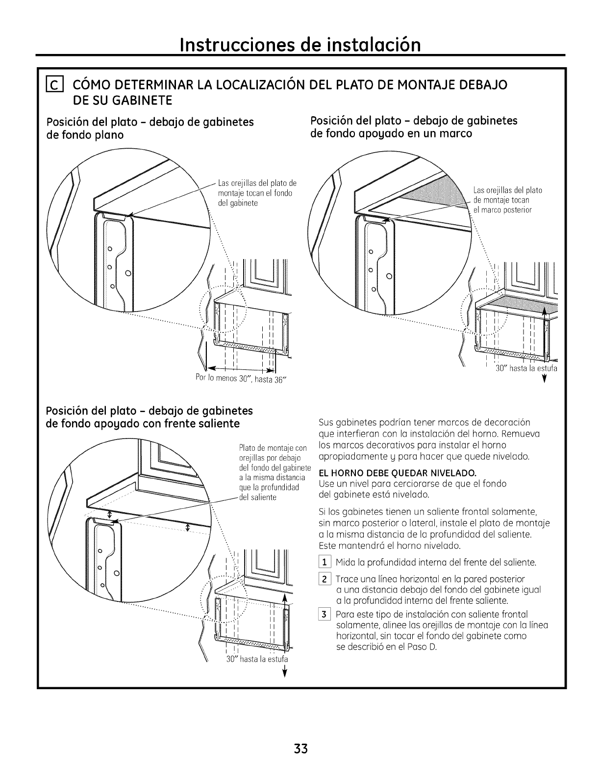
Posici6n del plato - debajo de gabinetes
de fondo piano
Posici6n del plato - debajo de gabinetes
de fondo apogado en un marco
Lasorejillas del platode
montajetocanel fondo
del gabinete
Lasorejillasdel plato
de montajetocan
el marco}osterior
Por Io menos 30", hasta 36"
' 30"hastalaestufa
V
Posici6n del plato - debajo de gabinetes
de fondo apogado con frente saliente
Platodemontajecon
orejillaspordebajo
delfondodel gabinete
a la mismadistancia
quela profundidad
saliente
30" hastalaestufa
Sus gabinetes podr[an tener marcos de decoraci6n
que interfieran con la instalaci6n del homo. Remueva
los marcos decorativos para instalar el homo
apropiadamente y para hacer que quede nivelado.
ELHORNO DEBE OUEDARNIVELADO.
Use un nivel para cerciorarse de que el fondo
del gabinete estci nivelado.
Si los gabinetes tienen un saliente frontal solamente,
sin marco posterior o lateral, instale el plato de montaje
a la misma distancia de la profundidad del saliente.
Este mantendrci el homo nivelado.
_i_ Mida la profundidad interna del frente del saliente.
1_ Trace una Ifnea horizontal en la pared posterior
a una distancia debajo del fondo del gabinete igual
a la profundidad interna del frente saliente.
[_ Para este tipo de instalaci6n con saliente frontal
solamente, alinee las orejillas de montaje con la Ifnea
horizontal, sin tocar el fondo del gabinete como
se describi6 en el Paso D.
33
Instrucciones de instalaci6n
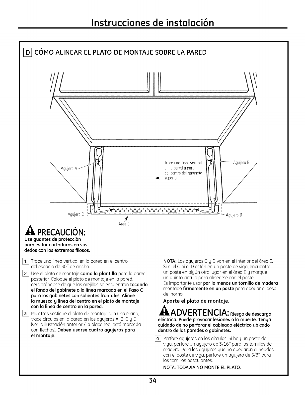
COMO ALINEAR EL PLATO DE MONTAJE SOBRE LA PARED
AgujeroA
Traceuna lineavertical
enla pareda partir
del centrodel gabinete
r_.- superior
AgujeroC
.Lk PRECAUCION:
Use guantes de protecci6n
para evitar cortaduras en sus
dedos con los extremos filosos.
O0000000lo0000000
00000000_00000000
i
AreaE i
I
I
IAgujeroD
[_] Trace una Ifneavertical en la pared en el centro
del espacio de 30" de ancho.
[_] Useel plato de montaje como la plantilla para la pared
posterior. Coloque el plato de montaje en la pared,
cerciordndose de que las orejillas se encuentran tocando
el fondo del gabinete o la linea marcada en el Paso C
para los gabinetes con salientes frontales. Alinee
la muesca g linea del centro en el plato de montaje
con la linea de centro en la pared.
[_] Mientras sostiene el plato de montaje con una mano,
trace cfrculos en la pared en los agujeros A, B, C y D
(ver la ilustraci6n anterior /la placa real est6 marcada
con flechas). Deben usarse cuatro agujeros para
el montaje.
NOTA:Los agujeros C g D van en el interior del 6rea E.
Si ni el C ni el D est6n en un poste de viga, encuentre
un poste en alg0n otro lugar en el 6rea Eg marque
un quinto drculo para alinearse con el poste.
Esimportante usar por Io menos un tornillo de madera
montado firmemente en un poste para apogar el peso
del homo.
Aparte el plato de montaje.
ADVERTENCIA:Riesgode descarga
el_ctrica. Puede provocar lesiones o la muerte. Tenga
cuidado de no perforar el cableado el_ctrico ubicado
dentro de las paredes o gabinetes.
[_ Perfore agujeros en los drculos. Si hag un poste de
viga, perfore un agujero de 3/16" para los tornillos de
madera. Para los agujeros que no quedaron alineados
con el poste de viga, perfore un agujero de 5/8" para
los tornillos basculantes.
NOTA:TODAViANO MONTEELPLATO.
34
Instrucciones de instalaci6n
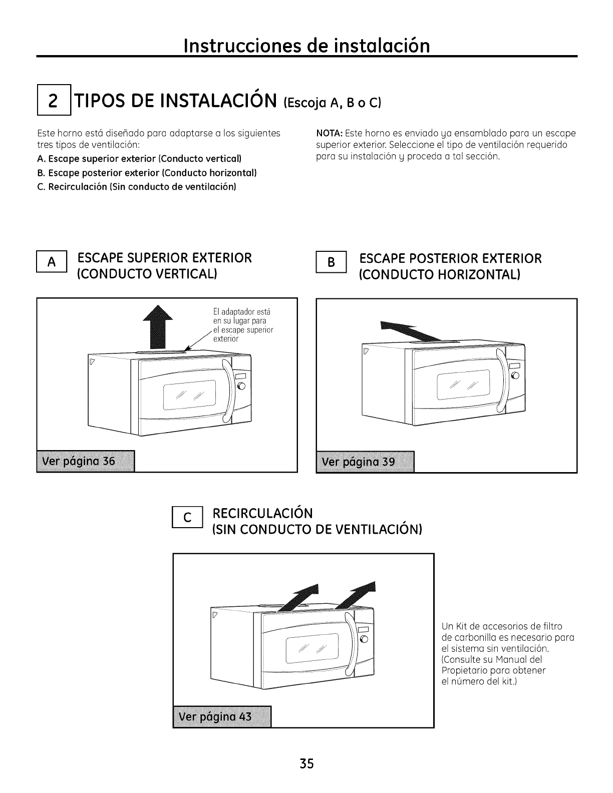
I-2ITIPOS DE INSTALACION
Este horno est6 dise_ado para adaptarse a los siguientes
tres tipos de ventilaci6n:
A. Escape superior exterior (Conducto vertical)
B. Escape posterior exterior (Conducto horizontal)
C. Recirculaci6n (Sin conducto de ventilaci6n)
(EscojaA, B o C)
NOTA:Estehornoes enviadoya ensamblado paraun escape
superiorexterior.Seleccioneeltipode ventilaci6nrequerido
para su instalaci6n g proceda a tal secci6n.
ESCAPE SUPERIOR EXTERIOR
(CONDUCTO VERTICAL) _1 SCAPE POSTERIOR EXTERIOR
(CONDUCTO HORIZONTAL)
Eladaptadorest_
ensu lugarpara
escapesuperior
exterior
I_1 RECIRCULACI6N
(SIN CONDUCTO DE VENTILACI6N)
Un Kit de accesorios de filtro
de carbonilla es necesario para
el sistema sin ventilaci6n.
(Consulte su Manual del
Propietario para obtener
el nOmero del kit.)
35
Instrucciones de instalaci6n
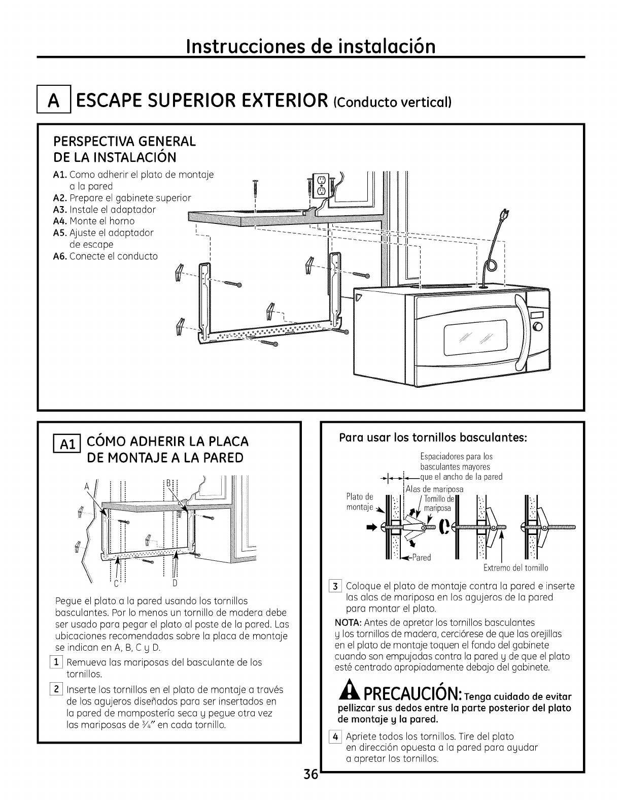
I-A-I ESCAPE SUPERIOR EXTERIOR (Conducto vertical)
PERSPECTIVA GENERAL
DE LA INSTALACION
A1. Como adherir el plato de montaje
a la pared _ _-I]_
A2. Prepare el gabinete superior ' _=A_t- J! II
A3. Instale el adaptador
A4. Monte el homo
A5. Ajuste el adaptador [__ ............. 2=_ti--L------------:L--
de escape , ,
A6. Conecte el conducto ', I
I
I
I-_ COMO ADHERIR LA PLACA
DE MONTAJE A LA PARED
=_
C: U
Pegue el plato a la pared usando los tornillos
basculantes. Por Io menos un tornillo de madera debe
ser usado para pegar el plato al poste de la pared. Las
ubicaciones recomendadas sobre la placa de montaje
se indican en A, B,C y D.
[_ Remueva las mariposas del basculante de los
tornillos.
I_ Inserte los tornillos en el plato de montaje a trav6s
de los agujeros dise_ados para ser insertados en
la pared de mamposterfa seca y pegue otra vez
las mariposas de 3/4"en cada tornillo.
36
Para usar los tornillos basculantes:
Espaciadoresparalos
basculantesmayores
-_l-,-_i_que el anchodela pared
IAlas demariposa
Platode
montaje_1_
Extremodeltornillo
[_ Coloque el plato de montaje contra la pared e inserte
las alas de mariposa en los agujeros de la pared
para montar el plato.
NOTA:Antes de apretar los tornillos basculantes
y los tornillos de madera, cerci6rese de que las orejillas
en el plato de montaje toquen el fondo del gabinete
cuando son empujadas contra la pared y de que el plato
est6 centrado apropiadamente debajo del gabinete.
nnl-/-^H/-i/_ !_i
rncv uv,u, : Tengacuidadodeevitar
pellizcar sus dedos entre la parte posterior del plato
de montaje yla pared.
[_ Apriete todos los tornillos. Tire del plato
en direcci6n opuesta a la pared para ayudar
a apretar los tornillos.
Instrucciones de instalaci6n
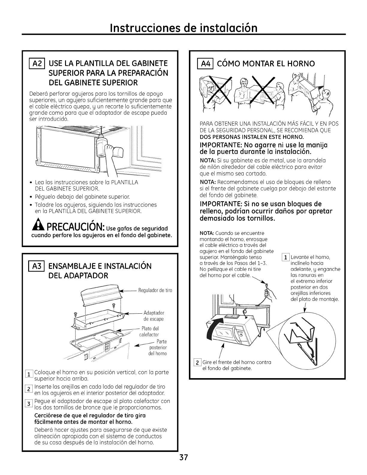
USE LA PLANTILLA DEL GABINETE
SUPERIOR PARA LA PREPARACI6N
DEL GABINETE SUPERIOR
Deber6 perforar agujeros para los tornillos de apoyo
superiores, un agujero suficientemente grande para que
el cable el@ctricoquepa, y un recorte Io suficientemente
grande coma para que el adaptador de escape pueda
ser introducido.
• Lea las instrucciones sabre la PLANTILLA
DELGABINETESUPERIOR.
• P6guelo debajo del gabinete superior.
• Taladre los agujeros, siguiendo las instrucciones
en la PLANTILLADELGABINETESUPERIOR.
nni-P^l IPI/_LI
I"nI-L,/'_UL, IUI_I: Use galas de seguridad
cuando perforelosagujeros en elrondo del gabinete.
ENSAMBLAJE E INSTALACI6N
DEL ADAPTADOR
Reguladorde tiro
?
h._ __--_ Adaptador
,_i_ deescape
i Platodel
I calefactor
Parte
posterior
_._;T .... delhomo
_i_ Coloque el horno en su posici6n vertical, con la parte
superior hacia arriba.
_] Inserte las orejillas en cada lado del regulador de tiro
en los agujeros en el interior posterior del adaptador.
[_ Pegue el adaptador de escape al plato calefactor con
los dos tornillos de bronce que le proporcionamos.
Cerci6rese de que el regulador de tiro gira
f6cilmente antes de montar el horno.
Deber6 hacer ajustes para osegurarse de que existe
alineaci6n apropiada con el sistema de conductos
de su casa despu@sde la instalaci6n del horno.
C6MO MONTAR EL HORNO
PARAOBTENERUNA INSTALACIONMAS FACILY EN POS
DE LA SEGURIDADPERSONAL,SERECOMIENDAC)UE
DOS PERSONASINSTALENESTEHORNO.
IMPORTANTE: No egerre ni use le menije
de le puerte durante la instaleci6n.
NOTA: Si su gabinete es de metal, use la arandela
de nil6n alrededor del cable el6ctrico para evitar
que el mismo sea cortado.
NOTA: Recomendamos el usa de bloques de relleno
si el frente del gabinete cuelga par debajo del estante
del fondo del gabinete.
IMPORTANTE: Si no se usan bloques de
relleno, podrian ocurrir da_os por apretar
demasiado los tornillos.
NOI'A: Cuando se encuentre
montando el homo, enrosque
el cable el_ctrico a trav_s del
agujero en el fondo del gabinete
superior. Mant_ngalo tenso
a trav_s de los Pasos del 1-3.
No pellizque el cable ni tire
del horno par
_i_ Levante el homo,
inclinelo hacia
adelante, y enganche
las ranuras en
el extremo inferior
posterior en dos
orejillas inferiores
del plato de montaje.
/
[] Gireel frente del horno contra
el fondo del gabinete.
37
Instrucciones de instalaci6n
COMO MONTAR EL HORNO
[continuaci6n)
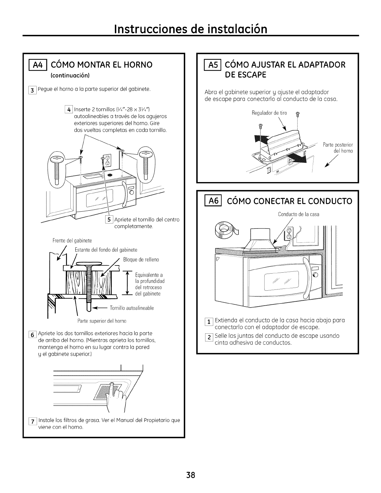
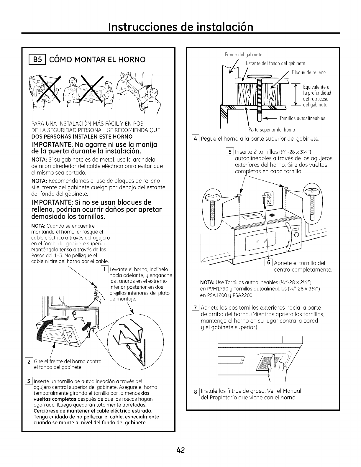
[_ Pegue el horno a la parte superior del gabinete.
[_ Inserte 2 tornillos (VJ'-28 x 3VJ')
autoalineables a trav_s de los agujeros
exteriores superiores del horno. Gire
dos vueltas completas en cada tornillo.
Apriete el tornillo del centro
completamente.
Frentedel gabinete
Estantedel fondodel gabinete
Bloquede relleno
_ quivalentea
la profundidad
del retroceso
del gabinete
Tornilloautoalineable
Partesuperiordel homo
[] Apriete los dos tornillos exteriores hacia la parte
de arriba del horno. (Mientras aprieta los tornillos,
mantenga el homo en su lugar contra la pared
y el gabinete superior.)
J
_/
[_ Instale los filtros de grasa. Ver el Manual del Propietario que
viene con el horno.
C6MOAJUSTAR EL ADAPTADOR
DE ESCAPE
Abra el gabinete superior Uajuste el adaptador
de escape para conectarlo al conducto de la casa.
Reguladordetiro
_i_ " Parteposterior
del homo
%/
COMO CONECTAR EL CONDUCTO
Condu_'tode la rasa
_!_ Extienda el conducto de la casa hacia abajo para
conectarlo con el adaptador de escape.
I_ Selle lasjuntas del conducto de escape usando
c,nta adhesiva de conductos.
38
Instrucciones de instalaci6n
ESCAPEPOSTERIOR
PERSPECTIVA GENERAL
DE LA INSTALACION
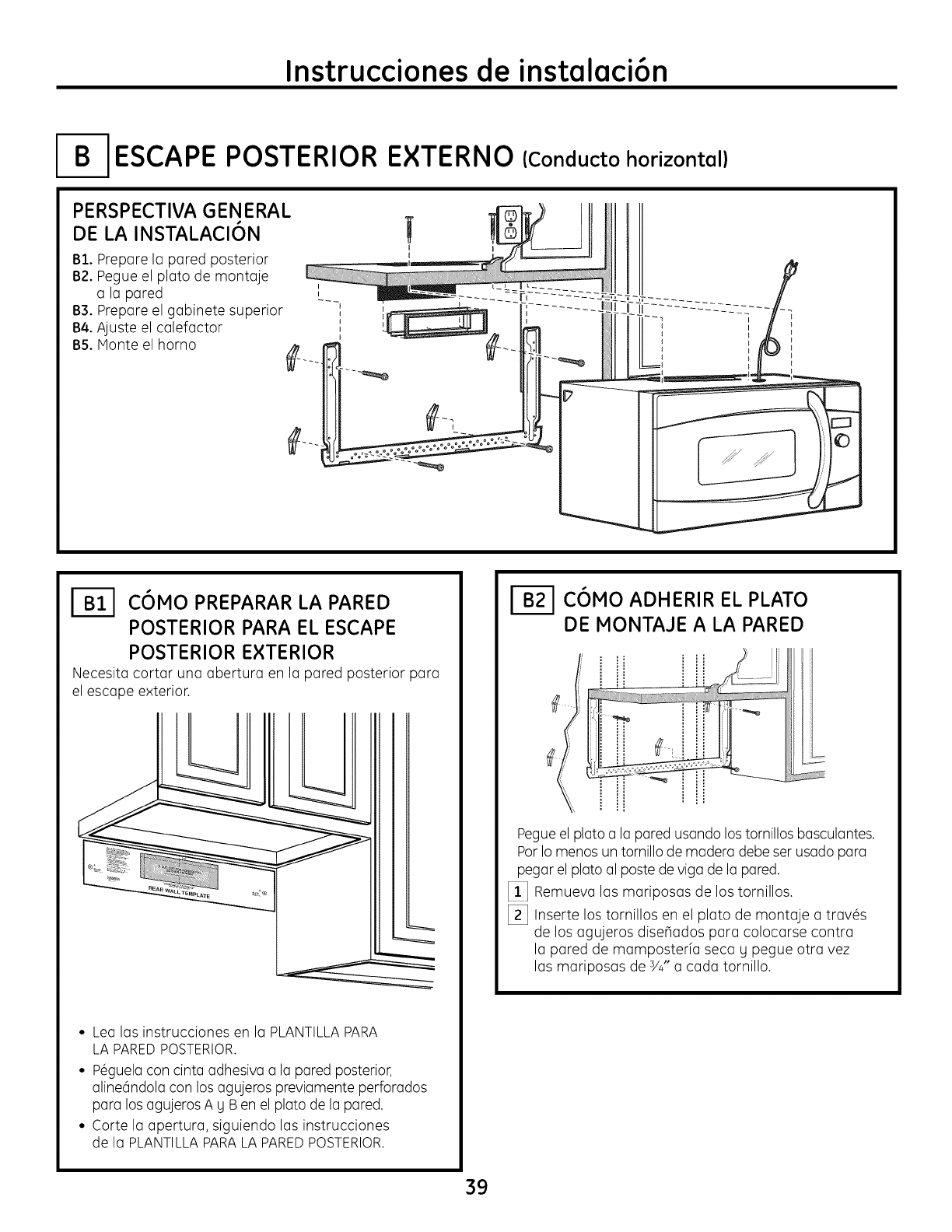
BI. Prepare la pared posterior
B2. Pegue el plato de montaje
a la pared
B3. Prepare el gabinete superior
B4. Ajuste el colefoctor
B5. Monte el homo
I
I
EXTERNO
!I
I
II
(Conducto horizontal)
COMO PREPARAR LA PARED
POSTERIOR PARA EL ESCAPE
POSTERIOR EXTERIOR
Necesita cortar una abertura en la pared posterior para
el escape exterior.
• Lea las instrucciones en la PLANTILLA PARA
LA PARED POSTERIOR.
• P_guelacon cinta adhesiva a la pared posterior,
aline6ndola con los agujeros previamente perforados
para los agujeros A g Ben el plato de la pared.
• Corte la apertura, siguiendo las instrucciones
de la PLANTILLAPARALA PAREDPOSTERIOR.
C6MOADHERIR EL PLATO
DE MONTAJE A LA PARED
Pegueel plato a la pared usando los tornillos basculantes.
Por Io menos un tornillo de madera debe ser usado para
pegar el plato al poste de viga de la pared.
[_ Remueva las mariposas de los tornillos.
[_ Inserte los tornillos en el plato de montaje a trav_s
de los agujeros dise_ados para colocarse contra
la pared de mamposterfa seca g pegue otra vez
las mariposas de 3/4"a cada tornillo.
39
Instrucciones de instalaci6n
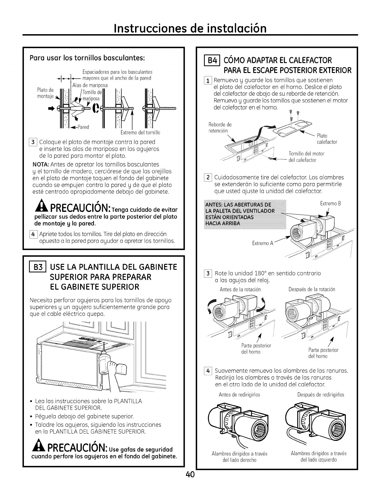
Para usar los tornillos basculantes:
Platode
montaje
Espaciadoresparalosbasculantes
-_l_-_i_ mayoresque el anchode la pared
IAlas demariposa
Extremodel tornillo
[] Coloque el plato de montaje contra la pared
e inserte las alas de mariposa en los agujeros
de la pared para montar el plato.
NOTA:Antes de apretar los tornillos basculantes
g el tornillo de madera, cerci6rese de que las orejillas
en el plato de montaje toquen el fondo del gabinete
cuando se empujen contra la pared g de que el plato
est_ centrado apropiadamente debajo del gabinete.
nn I-/"^H/"1/_ L I
rnc u M : Tengacuidadodeevitar
pellizcar sus dedos entre la parte posterior del plato
de montaje yla pared.
[_ Apriete todos lostornillos. Tire del plato en direcci6n
opuesta a la pared para ayudar a apretar los tornillos.
USE LA PLANTILLA DEL GABINETE
SUPERIOR PARA PREPARAR
EL GABINETE SUPERIOR
Necesita perforar agujeros para los tornillos de apogo
superiores gun agujero suficientemente grande para
que el cable el@ctrico quepa.
• Lea las instrucciones sobre la PLANTILLA
DELGABINETESUPERIOR.
• P6guela debajo del gabinete superior.
• Taladre los agujeros, siguiendo las instrucciones
en la PLANTILLADEL GABINETESUPERIOR.
PRECAUCION:Use gafas de seguridad
cuando perfore los agujeros en el fondo del gabinete.
C6MOADAPTARELCALEFACTOR
PARAEL ESCAPEPOSTERIOREXTERIOR
[_ Remueva y guarde los tornillos que sostienen
el plato del calefactor en el homo. Desliceel plato
del calefactor de abajo de su reborde de retenci6n.
Remueva y guarde los tornillos que sostienen el motor
del calefactor en el horno.
Rebordede L_ ji!_
\ _ ._-_J " -_" Plato
__ calefactor
Tom,,o ,moto
...._ 3_" _ delcalefactor
[_ Cuidadosamente tire del calefactor. Los alambres
se extender6n Io suficiente como para permitirle
que usted ajuste la unidad del calefactor.
ExtremoB
ExtremoA
[_ Rote la unidad 180° en sentido contrario
alas agujas del reloj.
Antes dela rotaci6n Despu6sde la rotaci6n
Parteposterior
delhomo Parteposterior
delhomo
[_ Suavemente remueva los alambres de las ranuras.
Redirija los alambres a tray,s de las ranuras
en el otro lado de la unidad del calefactor.
Antesderedirigirlos
Alambresdirigidosatrav6s
delladoderecho
Despu6sderedirigirlos
Alambresdirigidosa trav6s
del ladoizquierdo
40
Instrucciones de instalaci6n
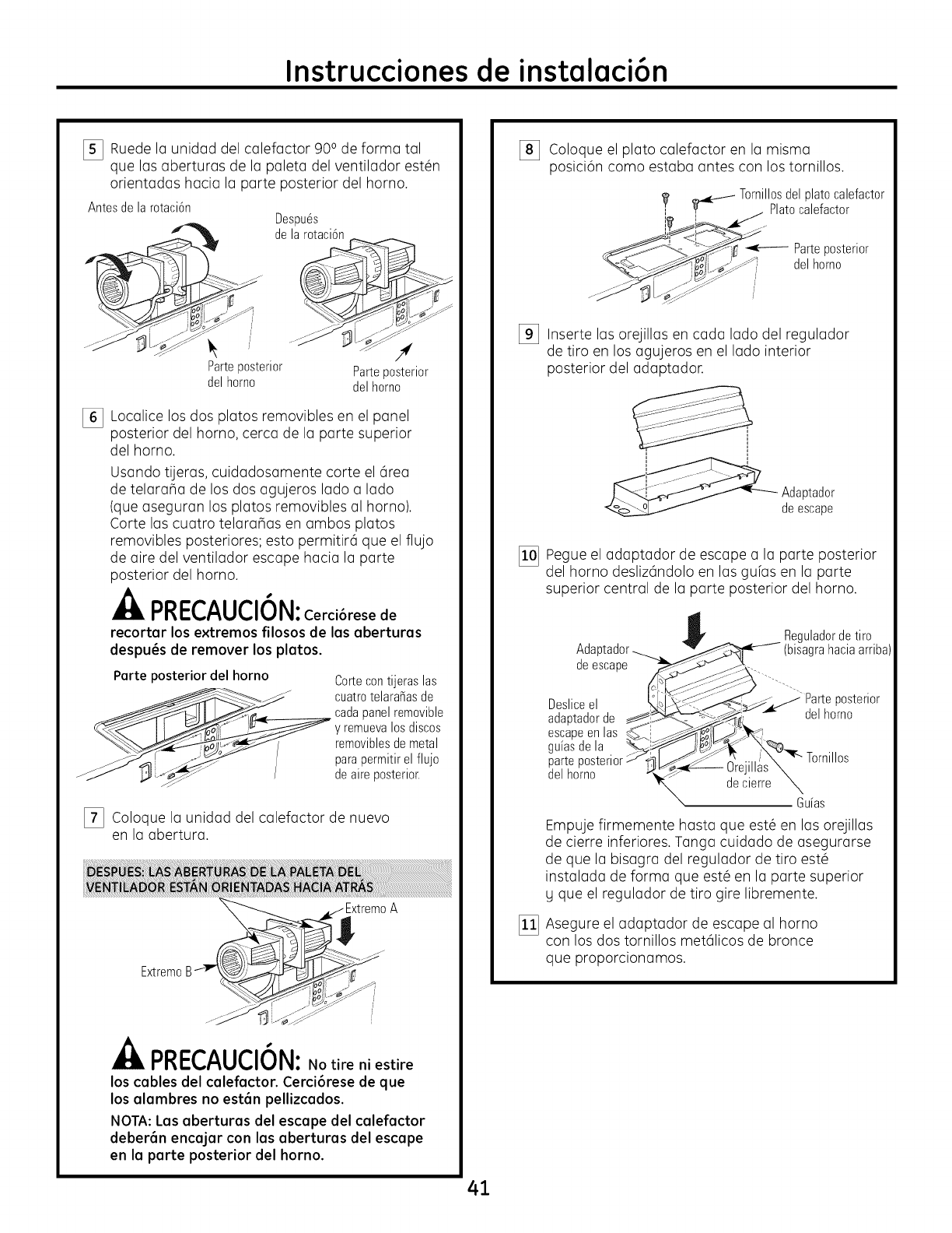
[_ Ruede la unidad del calefactor 90° de forma tal
que las aberturas de la paleta del ventilador est_n
orientadas hacia la parte posterior del horno.
Antesdelarotaci6n
Parteposterior
delhomo
Despu6s
de la rotaci6n
Parteposterior
delhomo
[] Localice los dos platos removibles en el panel
posterior del homo, cerca de la parte superior
del homo.
Usando tijeras, cuidadosamente corte el 6rea
de telarana de los dos agujeros lado a lado
(que aseguran los platos removibles al homo).
Corte las cuatro telaranas en ambos platos
removibles posteriores; esto permitir6 que el flujo
de aire del ventilador escape hacia la parte
posterior del horno.
PRECAUCI6N: Cerci6resede
recortar lose×tremos filosos de las aberturas
despu6s de remover los platos.
Parte posterior del horno Cortecontijeras las
cuatrotelara_asde
cadapanelremovible
y remuevalos discos
removiblesde metal
parapermitirel flujo
deaire )osterior.
[_ Coloque la unidad del calefactor de nuevo
en la abertura.
ExtremoB
nnl_r, AHr, l_kl
I"I_C_,,/'_M_,,IVI_I: NOtire ni estire
los cables del calefactor. Cerci6rese de que
los alambres no est6n pellizcados.
NOTA: Las aberturas del escape del calefactor
deber6n encajar con las aberturas del escape
en la parte posterior del horno.
41
[_ Coloque el plato calefactor en la misma
posici6n como estaba antes con los tornillos.
Tornillosdelplatocalefactor
_ Platocalefactor
Parteposterior
delhomo
[_ Inserte las orejillas en cada lado del regulador
de tiro en los agujeros en el lado interior
posterior del adaptador.
Adaptador
deescape
[]!_] Pegue el adaptador de escape a la parte posterior
del homo desliz6ndolo en las guias en la parte
superior central de la parte posterior del horno.
[]
Ada
deescape
Desliceel
adaptadorde
escapeenlas
guiasdela
parteI
del homo
Reguladordetiro
(bisagrahaciaarriba
Gdas
Empuje firmemente hasta que est6 en las orejillas
de cierre inferiores. Tanga cuidado de asegurarse
de que la bisagra del regulador de tiro est6
instalada de forma que est6 en la parte superior
y que el regulador de tiro gire libremente.
Asegure el adaptador de escape al homo
con los dos tornillos met61icos de bronce
que proporcionamos.
Instrucciones de instalaci6n
COMO MONTAR EL HORNO
PARA UNA INSTALACION MAS FACIL Y EN POS
DE LA SEGURIDAD PERSONAL, SE RECOMIENDA OUE
DOS PERSONAS INSTALEN ESTE HORNO.
IMPORTANTE: No agarre ni use la manija
de la puerta durante la instalaci6n.
NOTA: Si su gabinete es de metal, use la arandela
de nil6n alrededor del cable el@ctrico para evitar que
el mismo sea cortado.
NOTA: Recomendamos el usa de bloques de relleno
si el frente del gabinete cuelga par debajo del estante
del fondo del gabinete.
IMPORTANTE: Si no se usan bloques de
relleno, podrian ocurrir da_os por apretar
demasiado los tornillos.
NOTA: Cuundo se encuentre
montundo el homo, enrosque el
cable el_ctrico u troves del ugujero
en el fondo del gubinete superior.
Munt_ngolo tenso u troves de los
Posos del 1-3. No pellizque el
cable ni tire del homo par el cable.
[_ Levunte el homo, inclinelo
huciu odelunte, y engunche
los runurus en el extremo
inferior posterior en dos
orejillus inferiores del pluto
de montuje.
[_ Gire el frente del horno contru
el fondo del gubinete.
[_ Inserte un tornillo de uutoolineuci6n u troves del
ugujero central superior del gubinete. Asegure el horno
temporulmente girundo el tornillo par Io menos dos
vueltas completas despu_s de que los roscus hogan
ugurrudo. (Luego quedur6n totulmente upretudus).
Cerci6rese de mantener el cable el_ctrico estirado.
Tenga cuidado de no pellizcar el cable, especialmente
cuando se monte al nivel del fondo del gabinete.
Frentedel gabinete
Estantedel fondo del gabinete
Bloquede relleno
Z quivalentea
la profundidad
del retroceso
del gabinete
Tornillosautoalineables
Partesuperiordelhomo
[_ Pegue el homo a la parte superior del gabinete.
[_ Inserte 2 tornillos (Y4"-28x 3YJ')
autoalineables a trav@sde los agujeros
exteriores del homo. Gire dos vueltas
completas en cada tornillo.
)riete el tornillo del
centro completamente.
NOTA: Use Tornillos autoalineables (VJ'-28 x 2s/8")
en PVM1790 y Tornillos autoalineables (_/J'-28 x 3VJ')
en PSA1200 y PSA2200.
[] Apriete los dos tornillos exteriores hacia la parte
de arriba del homo. (Mientras aprieta los tornillos,
mantenga el homo en su lugar contra la pared
y el gabinete superior.)
[_ Instale los filtros de grasa. Ver el Manual
del Propietario que viene con el horno.
42
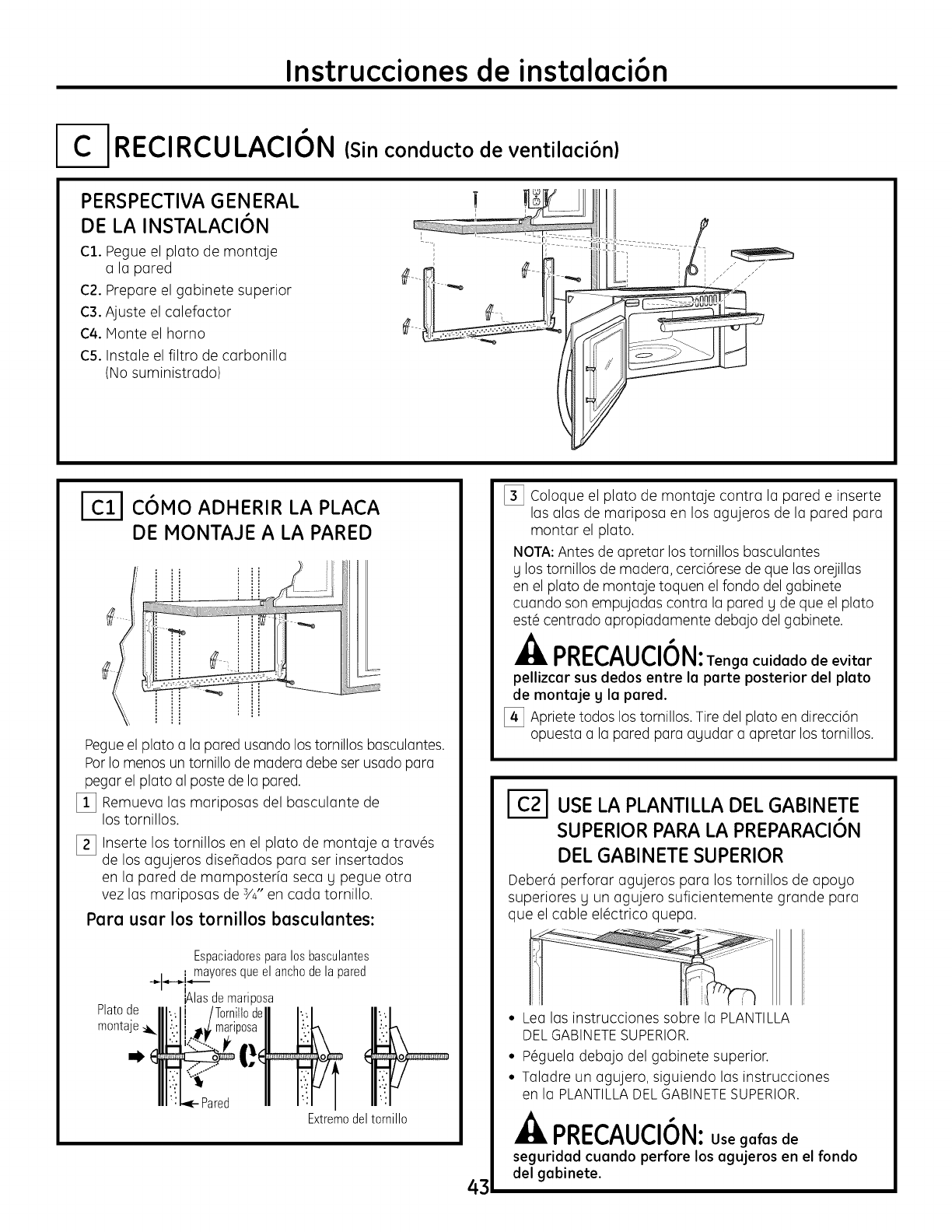
Instrucciones de instalaci6n
RECIRCULACI6N (Sin conducto de ventilaci6n)
PERSPECTIVA GENERAL
DE LA INSTALACION
C1. Pegue el plato de montaje
a la pared
C2. Prepare el gabinete superior
C3. Ajuste el calefactor
C4. Monte el horno
C5. Instale el filtro de carbonilla
(No suministrado)
C6MO ADHERIR LA PLACA
DE MONTAJE A LA PARED
Pegueel plato a la pared usando los tornillos basculantes.
PorIo menos un tornillo de madera debe ser usado para
pegar el plato al poste de la pared.
[]!_] Remueva las mariposas del basculante de
los tornillos.
[_] Inserte los tornillos en el plato de montaje a trav@s
de los agujeros diseBados para ser insertados
en la pared de mamposterfa seca g pegue otra
vez las mariposas de s/4"en cada tornillo.
Para usar los tornillos basculantes:
Espaciadoresparalosbasculantes
mayoresqueelanchodelapared
I
jAlasdemanposa
Platode
montaje _1_
Extremodel tornillo
43
[_] Coloque el plato de montaje contra la pared e inserte
las alas de mariposa en los agujeros de la pared para
montar el plato.
NOTA:Antes de apretar los tornillos basculantes
g los tornillos de madera, cerci6rese de que las orejillas
en el plato de montaje toquen el fondo del gabinete
cuando son empujadas contra la pared g de que el plato
est@centrado apropiadamente debajo del gabinete.
PRECAUCION:Tenga cuidado de evitar
pellizcar sus dedos entre la parte posterior del plato
de montaje g la pared.
[_ Apriete todos los tornillos. Tire del plato en direcci6n
opuesta a la pared para agudar a apretar los tornillos.
USE LA PLANTILLA DEL GABINETE
SUPERIOR PARA LA PREPARACI6N
DEL GABINETE SUPERIOR
Deberd perforar agujeros para los tornillos de apogo
superiores gun agujero suficientemente grande para
que el cable el@ctrico quepa.
• Lea las instrucciones sobre la PLANTILLA
DELGABINETESUPERIOR.
• P6guela debajo del gabinete superior.
• Taladre un agujero, siguiendo las instrucciones
en la PLANTILLADEL GABINETESUPERIOR.
PRECAUCION:Use galas de
seguridad cuando perfore los agujeros en el rondo
del gabinete.
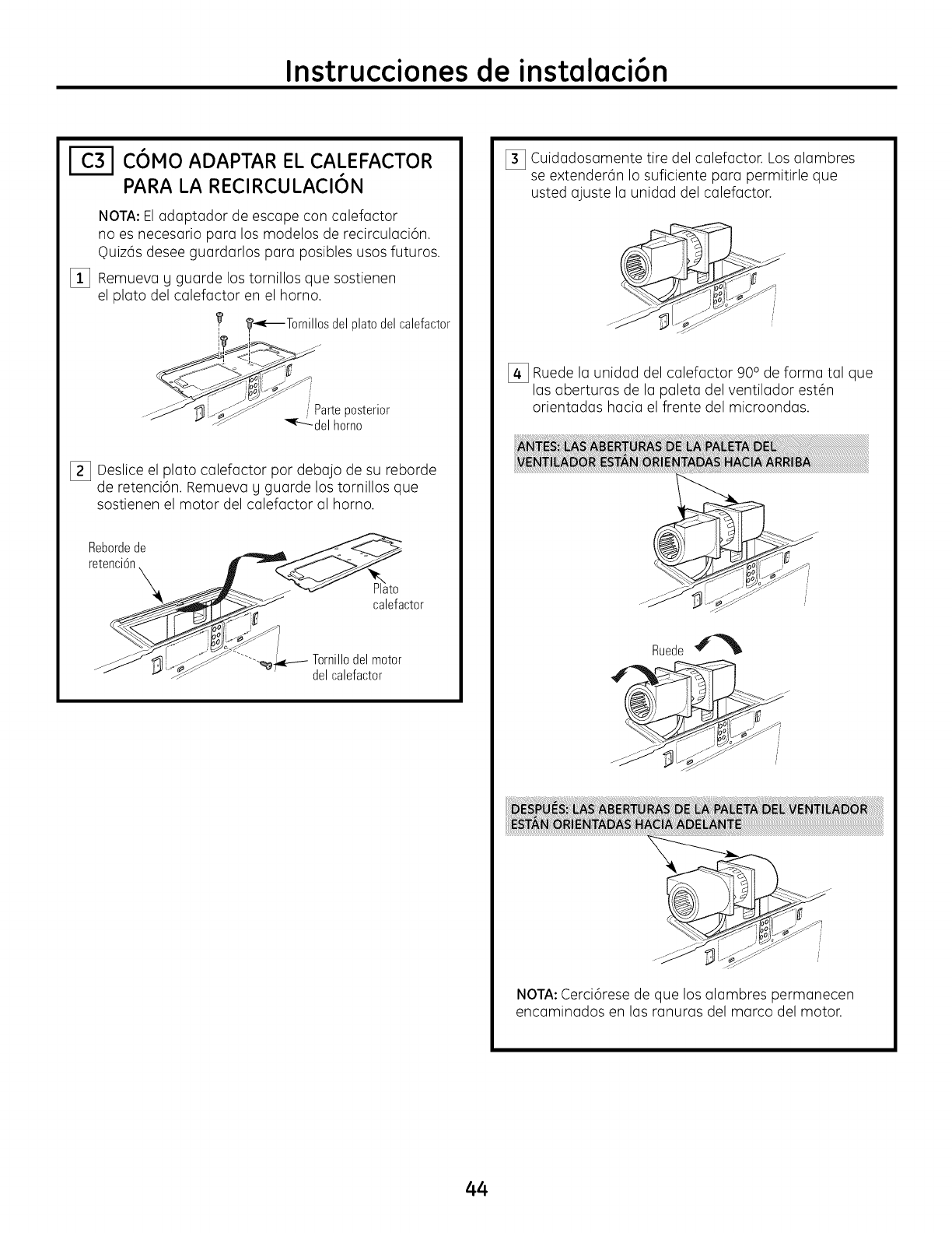
Instrucciones de instalaci6n
[--_ COMO ADAPTAR EL CALEFACTOR
PARA LA RECIRCULACION
NOTA: El adaptador de escape con calefactor
no es necesario para los modelos de recirculaci6n.
Ouiz6s desee guardarlos para posibles usos futuros.
_i_ Remueva g guarde los tornillos que sostienen
el plato del calefactor en el horno.
_€-_Tornillos delplatodelcalefactor
...... 'II ,_-}..._......_" <Parteposterior
...._ _ '_ _L delhomo
I_ Deslice el plato calefactor por debajo de su reborde
de retenci6n. Remueva g guarde los tornillos que
sostienen el motor del calefactor al horno.
Rebordede
retenci6n
\to
calefactor
Tornillodel motor
del calefactor
[_ Cuidadosamente tire del calefactor. Los alambres
se extender6n Io suficiente para permitirle que
usted ajuste la unidad del calefactor.
[_ Ruede la unidad del calefactor 90ode forma tal que
las aberturas de la paleta del ventilador est6n
orientadas hacia el frente del microondas.
Ruede
NOTA:Cerci6rese de que los alambres permanecen
encaminados en las ranuras del marco del motor.
44
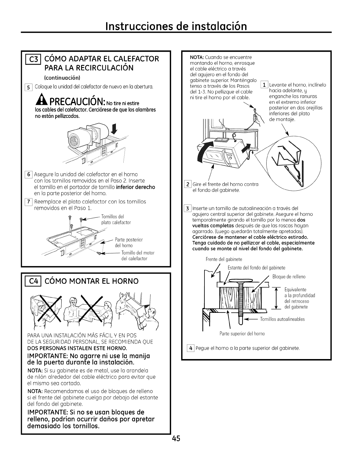
Instrucciones de instalaci6n
COMa ADAPTAR EL CALEFACTOR
PARA LA RECIRCULACION
(continuaci6n)
[_ Coloquela unidaddelcalefactordenuevoen laabertura.
PRECAUCION:Notire ni estire
loscablesdelcalefactor.Cerci6resedeque losalambres
noest6npellizcados.
[_ Asegure la unidad del calefactor en el horno
con los tornillos removidos en el Paso 2. Inserte
el tornillo en el portador de tornillo inferior derecho
en la parte posterior del homo.
[_ Reemplace el plato calefactor con los tornillos
removidos en el Paso 1.
/- Tornillosdel
'_ _ plato calefactor
..... ,i •iil..._.fj_ Parteposterior
_.- _._J _ del homo
..-__"" Tornillodel motor
del calefactor
COMO MONTAR EL HORNO
PARA UNA INSTALACION HAS FACIL Y EN POS
DE LA SEGURIDAD PERSONAL, SE RECOMIENDA OUE
DOS PERSONAS INSTALEN ESTE HORNO.
IMPORTANTE: No agarre ni use la manila
de la puerta durante la instalaci6n.
NOTA: Si su gabinete es de metal, use la arandela
de nil6n alrededor del cable el_ctrico para evitar qua
el mismo sea cortado.
NOTA: Recomendamos el usa de bloques de relleno
si el frente del gabinete cuelga par debajo del estante
del fondo del gabinete.
IMPORTANTE: Si no se usan bloques de
relleno, podrian ocurrir tiaras par apretar
demasiado los tornillos.
NOTA: Cuando se encuentre
montando el homo. enrosque
el cable el_ctrico a tray,s
del agujero en el fondo del
gabinete superior. IVlant_ngalo
tenso atray,s de los Pasos
del 1-3. No pelJizque el cable
ni tire el homo par el cable.
_i_ Levante el homo, inclinelo
hacia adelante, y
enganche las ranuras
en el extremo inferior
posterior en dos orejillas
inferiores del pluto
de montaje.
[_ Gire el frente del horno contra
el fondo del gabinete.
[_ Inserte tornillo de autoalineaci6n del
un a tray,s
agujero central superior del gabinete. Asegure el horno
temporalmente girando el tornillo par Io menos dos
vueltas completas despu_s de qua las roscas hayan
agarrado. (Luego quedar6n totalmente apretadas).
Cerci6rese de mantener el cable el_ctrico estirado.
Tenga cuidado de no pellizcar el cable, especialmente
cuando se monte al nivel del fondo del gabinete.
Frentedel gabinete
Estantedel fondo del gabinete
Bloquede relleno
i quivalente
a la profundidad
del retroceso
del gabinete
Tornillosautoalineables
Partesuperiordel homo
[_ Pegue el homo a la parte superior del gabinete.
45
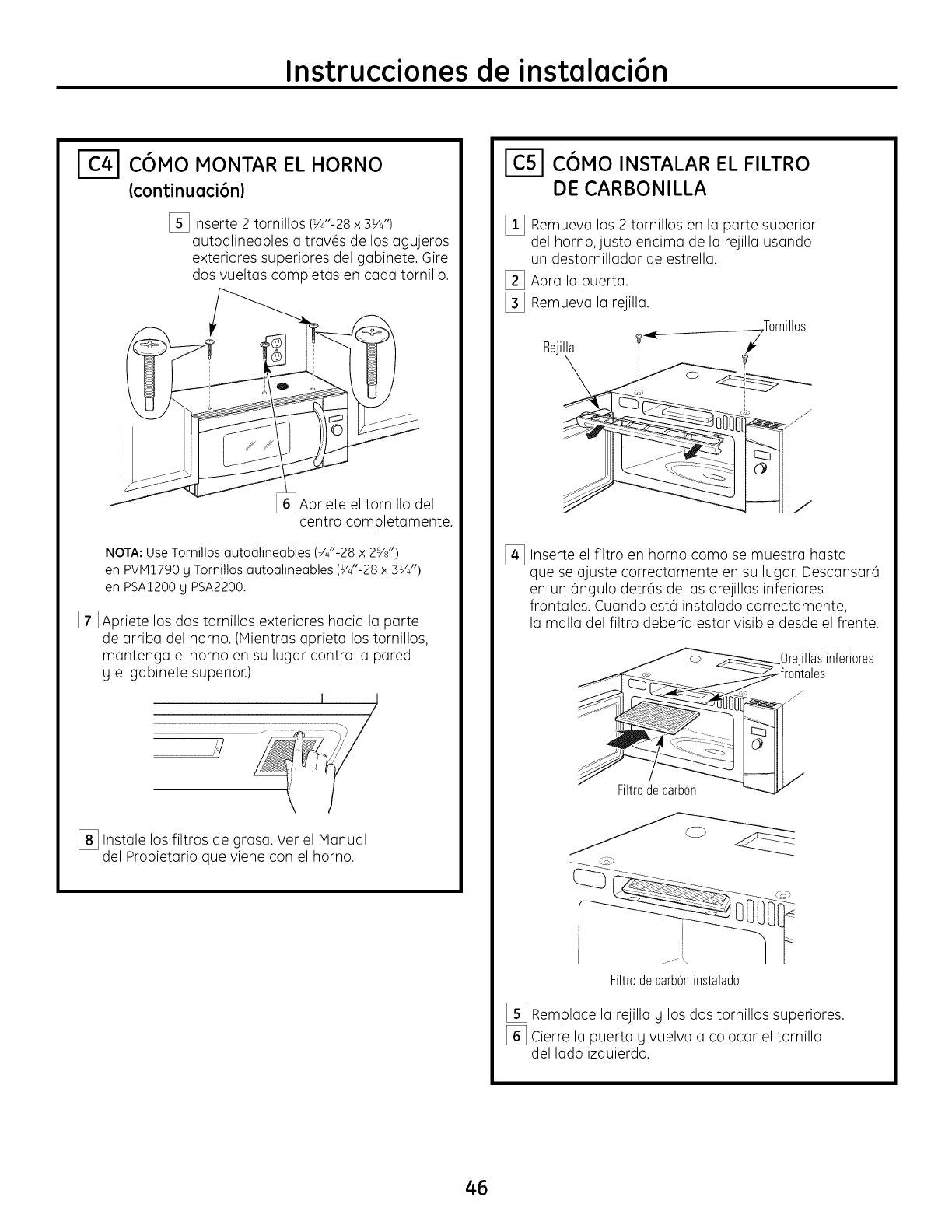
Instrucciones de instalaci6n
COMO MONTAR EL HORNO
(continuaci6n)
[_ Inserte 2 tornillos (VJ'-28x 3VJ')
autoalineobles a trav@sde los ogujeros
exteriores superiores del gobinete. Gire
dos vueltos completos en coda tornillo.
[_Apriete el tornillo del
centro completomente.
NOTA: Use Tornillos autoalineables (VJ'-28 x 2s/8")
en PVIVI1790 y Tornillos autoalineables (_/J'-28 x 3VJ')
en PSA1200 y PSA2200.
[] Apriete los dos tornillos exteriores hacio Io porte
de arriba del homo. (Mientras aprieta los tornillos,
mantenga el homo en su lugar contra la pared
y el gabinete superior.)
,, /
[_ Instale los filtros de grasa. Ver el Manual
del Propietario que viene con el horno.
C6MO INSTALAR EL FILTRO
DE CARBONILLA
[] Remueva los 2 tornillos en Io porte superior
del horno, justo encima de Io rejilla usando
un destornillador de estrella.
[_ Abra Io puerto.
[_ Remueva la rejilla.
Rejilia ?_Tornil
los
©
I
[_ Inserte el filtro en horno como se muestra hasta
que se ajuste correctamente en su lugar. Descansar(i
en un 6ngulo detr(is de los orejillas inferiores
frontales. Cuando est(i instalado correctamente,
la malla del filtro deberfa estar visible desde el frente.
illasinferiores
Filtrode carb6n
Filtrodecarb6ninstalado
[_ Remplace Io rejilla y los dos tornillos superiores.
[_ Cierre la puerta y vuelva a colocar el tornillo
del lado izquierdo.
46
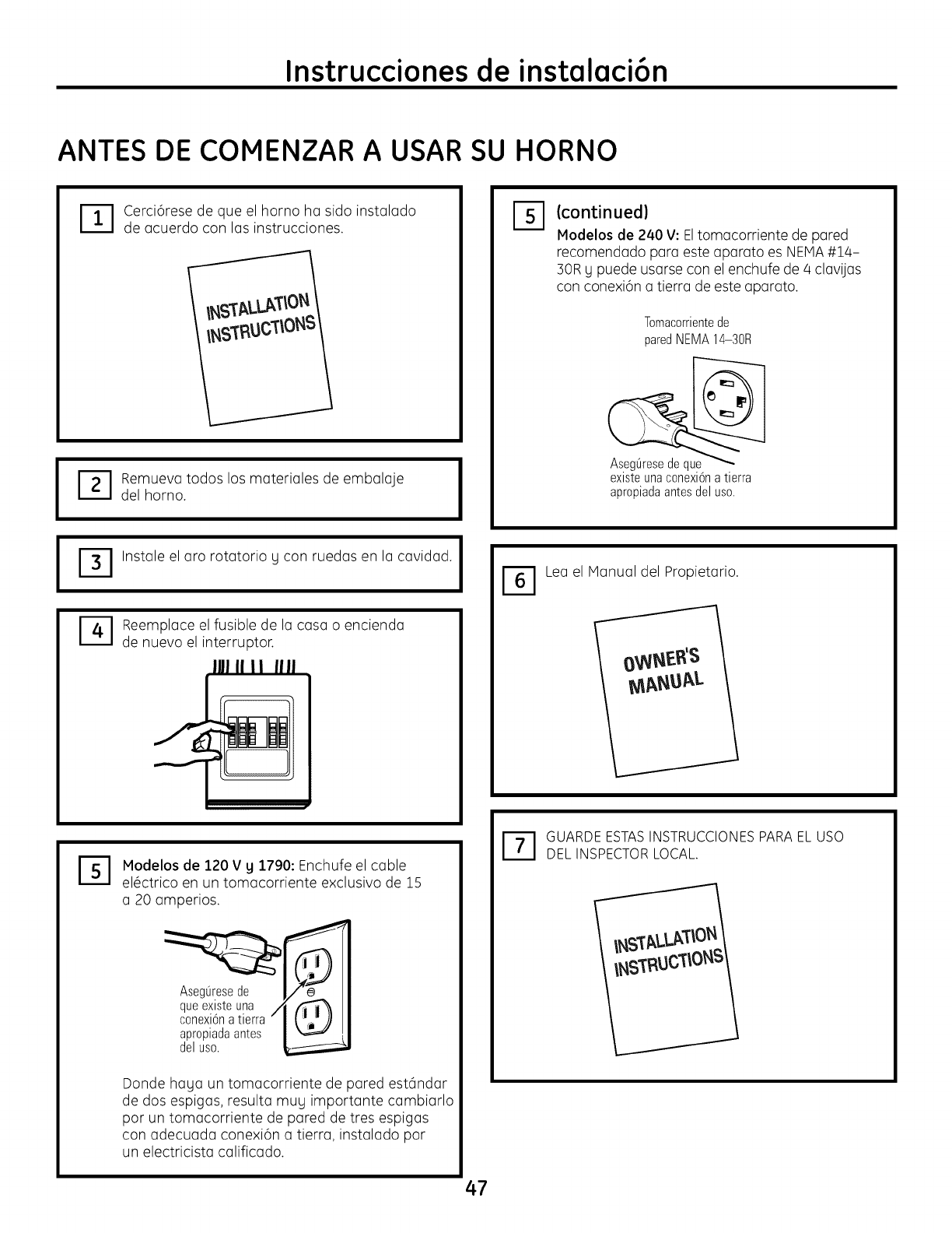
Instrucciones de instalaci6n
ANTES DE COMENZAR A USAR SU HORNO
I
I
-_ erci6rese de que el horno ha sido instalado
de acuerdo con las instrucciones.
r_ emueva todos los materiales de embalaje
del horno. I
Instale el aro rotatorio g con ruedas en la cavidad. I
Reemplace el fusible de la casa o encienda
de nuevo el interruptor.
IIII II II IIII
%(continued)
Modelos de 240 V: Eltomacorriente de pared
recomendado para este aparato es NEMA#14-
30R g puede usarse con el enchufe de 4 clavijas
con conexi6n a tierra de este aparato.
Tomacorrientede
paredNEMA14-30R
existe una conexi6n a tierra
apropiadaantesdelusa.
[_ Lea el Mlanual del Propietario.
%Modelos de 120 V y 1790: Enchufe el cable
el_ctrico en un tomacorriente exclusivo de 15
a 20 amperios.
AsegQresede
queexisteuna /
conexi6natierra
apropiada antes
delusa. 1
Donde haya un tomacorriente de pared est6ndar
de dos espigas, resulta muy importante cambiarlo
par un tomacorriente de pared de tres espigas
con adecuada conexi6n a tierra, instalado par
un electricista calificado.
r_ UARDE ESTAS INSTRUCCIONES PARA EL USO
DEL INSPECTOR LOCAL.
47

49-40611 I (06-09JR)
Printed in Koreo
Impreso en Coreo
