GE GFDN110GD2WW User Manual GAS DRYER Manuals And Guides 1211088L
User Manual: GE GFDN110GD2WW GFDN110GD2WW GE GAS DRYER - Manuals and Guides View the owners manual for your GE GAS DRYER #GFDN110GD2WW. Home:Laundry & Garment Care Parts:GE Parts:GE GAS DRYER Manual
Open the PDF directly: View PDF ![]() .
.
Page Count: 16
Installation
Instructions
Questions on Installation? Call: 800.GE.CARES {US) or 800-561-3344 {Canada)
or visit our web site at: www.GEAppliances.com (US)
'1@
Gas Dryer
10 ®
i
BEFORE YOU BEGIN
Read these instructions
completely and carefully.
* IMPORTANT- save
these instructions for local
inspector's use.
, IMPORTANT- Observe
all governing codes and
ordinances.
, Note to Installer - Be sure to
leave these instructions with
the customer.
* Note to Customer- Keepthese
instructions with your Owner's
Manual for future reference.
. Before the old dryer is removed
from service or discarded,
remove the dryer door.
. Service information and the
wiring diagram are located in
the control console.
. Do not allow children on
or in the appliance. Close
supervision of children is
necessary when the appliance
is used near children.
. Install the dryer where the
temperature is above 50°F for
satisfactory operation of the
dryer control system.
. Product failure due to
improper installation is not
covered under the Warranty.
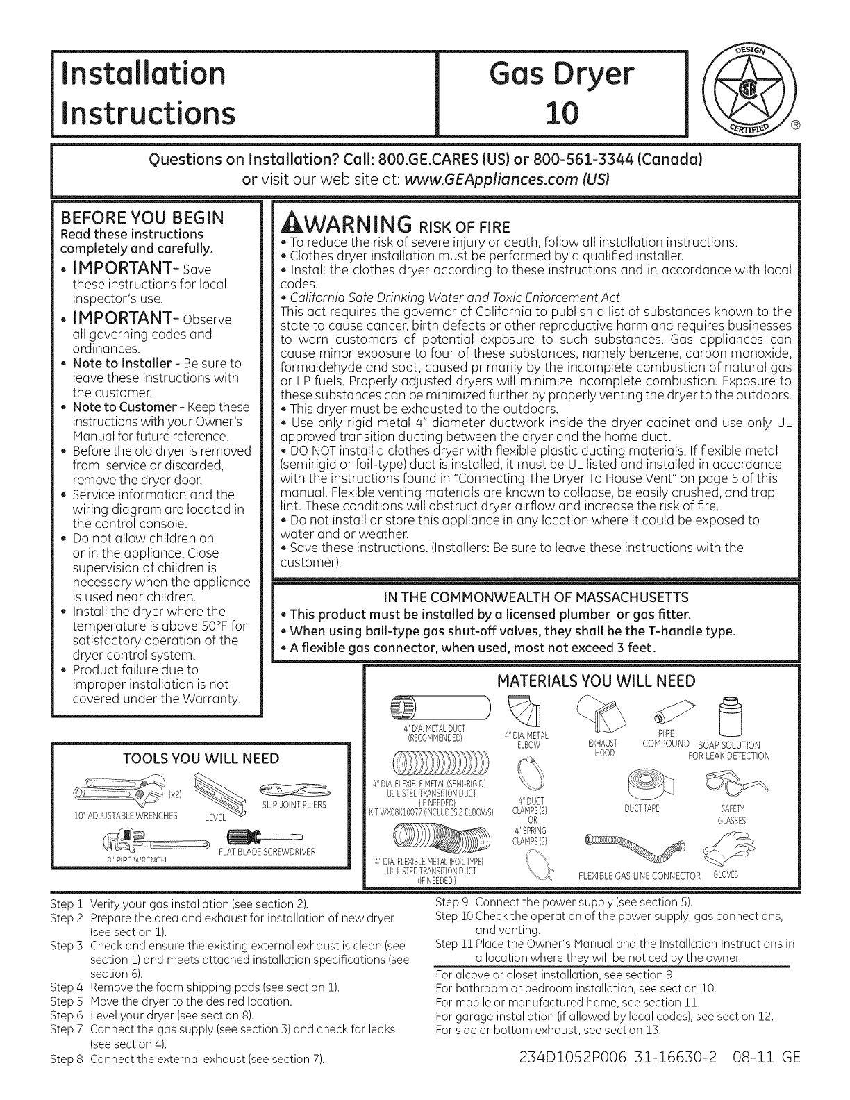
TOOLS YOU WILL NEED
(x2) %
10" ADJUSTABLEWRENCHES
WARI ING RISKOF FIRE
. To reduce tb risk of severe injury or death, follow all installation instructions.
. Clothes dry_ installation must be performed by a qualified installer.
. Install the clothes dryer according to these instructions and in accordance with local
codes.
• California Sc _ Drinking Water and Toxic Enforcement Act
This act requi the governor of California to publish a list of substances known to the
state to cause cancer, birth defects or other reproductive harm and requires businesses
to warn cast s of potential exposure to such substances. Gas appliances can
cause minor exposure to four of these substances, namely benzene, carbon monoxide,
formaldehy@ and soot, caused primarily by the incomplete combustion of natural gas
or LPfuels. Pr perly adjusted dryers will minimize incomplete combustion. Exposure to
these substan s can be minimized further by properly venting the dryer to the outdoors.
. This dryer m ;t be exhausted to the outdoors.
. Use only tic metal 4" diameter ductwork inside the dryer cabinet and use only UL
approved trar an ducting between the dryer and the home duct.
. DO NOTinst a clothes dryer with flexible plastic ducting materials. If flexible metal
(semirigid or foil-type)duct is installed, it must be UL listed and installed in accordance
with the instrt :tions found in "Connecting The Dryer To House Vent" on page 5 of this
manual. Flexff ._venting materials are known to collapse, be easily crushed, and trap
lint. These conditions will obstruct dryer airflow and increase the risk of fire.
. Do not insta or store this appliance in any location where it could be exposed to
water and or weather.
. Save these instructions. (Installers: Be sure to leave these instructions with the
customer).
IN THE COMMONWEALTH OF MASSACHUSETTS
, This produc st be installed by a licensed plumber or gas fitter.
, When using ball-type gas shut-off valves, they shall be the T-handle type.
, A flexible g( connector, when used, most not exceed 3 feet.
MATERIALS YOU WILL NEED
4"DIA,METALDUCT )% j_
(RECOMMENDED} 4"DIA,METAL
ELBOW COMPOUND SOAPSOLUTION
FORLEAKDETECTION
SLIPJOINTPLIERS
FLATBLADESCREWDRIVER
R" PIPE \A/RERII-M
Step i
Step 2
Step 3
4"DIA.FLEXIBLEMETAL(SEMFRIGID}
ULLISTEDTRANSITIONDUCT
(IFNEEDED}
KITWXOEXlOO77(INCLUDES2ELBOWS}
Step 4
Step 5
Step 6
Step 7
Step 8
PIPE
EXHAUST
HOOD
4"DUCT
CLAMPS(2} DUCTTAPE SAFETY
OR GLASSES
4"SPRING z%
CLAMPS121
4"DIA,FLEXIBLEMETAL(FOILTYPE} __:_f_::_')
ULLISTEDTRANSITIONDUCT
(IFNEEDED,} FLEXIBLEGASLINECONNECTOR GLOVES
Verify your gas installation (see section 2).
Prepare the area and exhaust for installation of new dryer
(see section !).
Check and ensure the existing external exhaust is clean (see
section 1)and meets attached installation specifications (see
section 6).
Remove the foam shipping pads (see section 1).
Move the dryer to the desired location.
Level your dryer (see section 8).
Connect the gas supply (see section 3) and check for leaks
(see section 4).
Connect the external exhaust (see section 7).
Step 9 Connect the power supply (see section 5).
Step 10Check the operation of the power supply, gas connections,
and venting.
Step 11Place the Owner's Manual and the Installation Instructions in
a location where they will be noticed by the owner.
For alcove or closet installation, see section 9.
For bathroom or bedroom installation, see section 10.
For mobile or manufactured home, see section 11.
For garage installation (if allowed by local codes), see section 12.
For side or bottom exhaust, see section 13.
234DlO52PO06 31-16630-2 08-11 GE

Installation instructions
Minimum Clearance Other Than Alcove or Closet Installation
Minimum clearance to combustible surfaces and for air opening are: 0 in. clearance both sides, ! in. front 3 in. rear.
Consideration must be given to provide adequate clearance for installation and service.
rl] PREPARING FOR INSTALLATION
OF NEW DRYER
TIP: Install your dryer before installing your washer.
This will allow better access when installing dryer
exhaust.
DISCONNECTING GAS
TURNGAS _ DISCONNECTAND DISCARDOLu'_ _
SHUT-OFF I_ FLEXIBLEGAS CONNECTORAND _J i'_w
VALVETOTHE _ OLD DUCTINGMATERIAL. T
APPROVEDFLEXIBLEGASLINE
CONNECTORAND ULAPPROVED
TRANSITIONDUCT.
WARNING- NEVERREUSE
OLD FLEXIBLE CONNECTORS.
The use of old flexible connectors can cause leaks
and personal injury. Always use new flexible
connectors when installing gas appliances.
REMOVING LINT FROM WALL EXHAUST
OPENING
. Remove and discard existing plastic or metal foil
transition duct and replace with UL listed transition duct.
INTERNALDUCT
OPENING
WALL
/
CHECKTHATEXHAUSE
i- HOODDAMPEROPENS
ANDCLOSESFREELY.
TILTTHE DRYERSIDEWAYS
AND REMOVETHE FOAM
SHIPPING PADS BY
PULLING ATTHE SIDES
AND BREAKING THEM
AWAY FROM THE DRYER
LEGS. BE SURE TO
REMOVE ALL OF THE
FOAM PIECESAROUND
THE LEGS.
r2] GAS REQUIREMENTS
WARNING
, Installation must conform to local codes and
ordinances,or in their absence, the NATIONALFUELGAS
CODE,ANSIZ223.
• This gas dryer is equipped with a Valve & Burner
Assembly for use only with natural gas. Using conversion
kit WE25X0217,your local service organization can
convert this dryer for use with propane (LP)gas. ALL
CONVERSIONSMUSTBEMADEBYPROPERLYTRAINED
AND QUALIFIEDPERSONNELAND IN ACCORDANCEWITH
LOCALCODESAND ORDINANCEREQUIREMENTS.
• The dryer must be disconnected from the gas supply
piping system during any pressure testing of that sys-
tem at a test pressure in excess of 0.5 PSI(3.4 KPa).
• The dryer must be isolated from the gas supply piping
system by closing the equipment shut-off valve during
any pressure testing of the gas supply piping of test
pressure equal to or less than 0.5 PSI(3.4 KPa).
DRYER GAS SUPPLY CONNECTION
2n
)
CD cD CD
0CD CD CD
C3CDO
3/8" NPT MALETHREADGAS SUPPLY
NOTE:Add to vertical dimension
the distance between cabinet
bottom to floor.
, A 1/8 in. National Pipe Taper thread plugged tapping,
accessible for test gauge connection, must be installed
immediately upstream of the gas supply connection to
the dryer. Contact your local gas utility should you have
questions on the installation of the plugged tapping.
, Supply line is to be !/2 in. rigid pipe and equipped with
an accessible shut-off within 6 ft. of, and in the same
room with the dryer.
, Use pipe thread sealer compound appropriate for natu-
ral or LPgas or use Teflon tape.
, Connect flexible metal connector to dryer and gas supply.
, Open shut-off valve.
, You must use with this dryer a flexible metal connector
(listed connector ANSIZ21.24 /CSA 6.10). The length of
the connect shall not exceed 3 ft.
ADJUSTING FOR ELEVATION
, Gas clothes dryers input ratings are based on sea level
operation and need not be adjusted for operation at or
below 2000 ft. elevation.
For operation at elevations above 2000 ft., input ratings
should be reduced at a rate of 4 percent for each 1000 ft.
above sea level.
, Installation must conform to local codes and ordinances or,
in their absence, the NATIONALFUELGASCODE,ANSIZ223.
Installation instructions
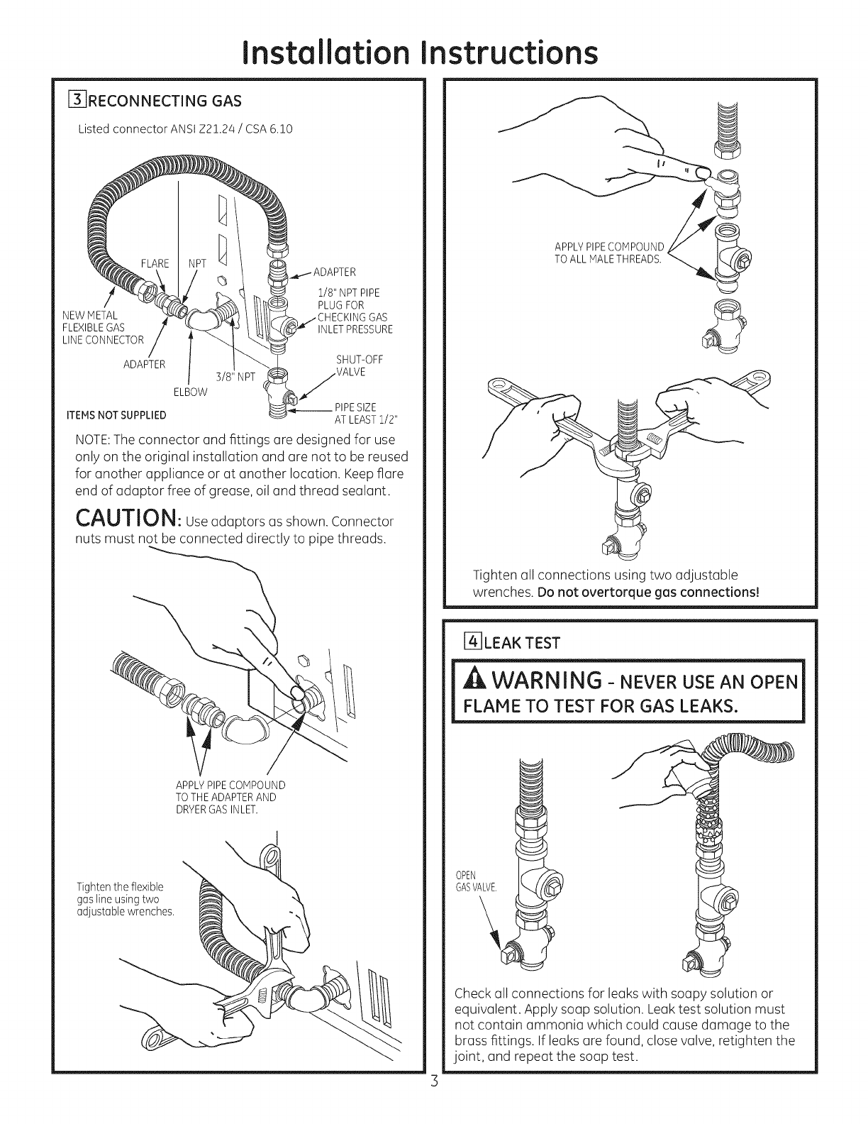
_]RECONNECTING GAS
Listed connector ANSI Z2!.24 /CSA 6.!0
1/8" NPTPIPE
PLUGFOR
NEWMETAL GAS
FLEXIBLEGAS INLETPRESSURE
LINECONNECTOR
ADAPTER SHUT-OFF
3/8" NPT VALVE
ELBOW
__PIPESIZE
ITEMSNOT SUPPLIED AT LEASTi/2"
NOTE: The connector ond fittings ore designed for use
only on the originol instollotion ond ore not to be reused
for onother opplionce or ot onother locotion. Keep fiore
end of odoptor free of grease, oil and thread sealant.
CAUTION: Useodoptorsosshown.Connector
nuts must not be connected directly to pipe threods.
\
APPLYPIPECOMPOUND
TO THEADAPTERAND
DRYERGASINLET.
Tighten the flexible
gas line using two
adjustable wrenches.
I
APPLYPIPECOMPOUND
TO ALL MALETHREADS.
Tighten oil connections using two odjustoble
wrenches. Do not overtorque ges connections!
[-4-]LEAK TEST
FLAME TO TEST FOR GAS LEAKS.
OPEN
GASVALVE.
Check all connections for leaks with soupy solution or
equivalent. Apply soup solution. Leuk test solution must
not contmin ammonia which could cause damage to the
brass fittings. If leaks are found, close vmlve,retighten the
joint, randrepemt the soup test.

Installation instructions
[_]ELECTRICAL CONNECTION iNFORMATiON
RISK OF FIRE, ELECTRICAL SHOCK, AND
PERSONAL INJURY:
• DO NOT USE AN EXTENSION CORD
OR AN ADAPTER PLUG WITH THIS
APPLIANCE.
Dryer must be electrically grounded in accordance
with local codes and ordinances, or in the absence
of local codes, in accordance with the NATIONAL
ELECTRICALCODE,ANSI/NFPANO.70.
ELECTRICAL REQUIREMENTS
This appliance must be supplied with 120V,60Hz, and
connected to a properly grounded branch circuit, pro-
tected by a 15- or 20-amp circuit breaker or time delay
fuse. If electrical supply provided does not meet the
above specifications, it is recommended that a licensed
electrician install an approved outlet.
EQUIPPED WITH A THREE-PRONG
(GROUNDING) PLUG FOR YOUR
PROTECTION AGAINST SHOCK HAZARD
AND SHOULD BE PLUGGED DIRECTLY
iNTO A PROPERLY GROUNDED THREE-
PRONG RECEPTACLE. DO NOT CUT OR
REMOVE THE GROUNDING PRONG
FROM THiS PLUG.
ENSURE PROPER GROUND EXISTS BEFORE USE
IF LOCAL CODES PERMIT,
AN EXTERNALGROUND WIRE
(NOT PROVIDED),WHICH MEETS
LOCAL CODES, MAY BE ADDED
BY ATTACHING TO THE GREEN
GROUND SCREW ON THE REAR
OF THE DRYER,AND TO A GROUNDED
METAL COLD WATER PIPEOR OTHER
ESTABLISHED GROUND.
[] EXHAUST INFORMATION
, WARNING -IN CANADA AND IN THE
UNITED STATES, THE REQUIRED EXHAUST
DUCT DIAMETER IS 4in (102mm). DO NOT
USE DUCT LONGER THAN SPECIFIED IN THE
EXHAUST LENGTH TABLE.
Using exhaust longer than specified length will:
. Increase the drying times and the energy cost.
. Reduce the dryer life.
. Accumulate lint, creating a potential fire hazard.
The correct exhaust installation is YOUR
RESPONSIBILITY.Problems due to incorrect
installation are not covered by the warranty.
Remove and discard existing plastic or metal foil
transition duct and replace with UL listed transition duct.
The MAXIMUM ALLOWABLE duct length and number of
bends of the exhaust system depends upon the type of
duct, number of turns, the type of exhaust hood (wall
cap), and all conditions noted below. The maximum duct
length for rigid metal duct is shown in the table below.
EXHAUST LENGTH
RECOMMENDEDMAXIMUM LENGTH
Exhaust Hood Types
Use only for short
Recommended run installations
No. of 90 °
Elbows
0
1
2
3
4
Rigid
Metal
90 Feet
60 Feet
/45 Feet
35 Feet
25 Feet
4" DIA.
Rigid
Metal
60 Feet
45 Feet
35 Feet
25 Feet
15 Feet
EXHAUST SYSTEM CHECK LIST
HOOD OR WALL CAP
. Terminate in a manner to prevent back drafts or entry of
birds or other wildlife.
. Termination should present minimal resistance to
the exhaust air flow and should require little or no
maintenance to prevent clogging.
. Never install ascreen in or over the exhaust duct. This
could cause lint build up.
. Wall caps must be installed at least 12 in. above ground
level or any other obstruction with the opening pointed
down.
SEPARATIONOF TURNS
For best performance, separate all turns by at least 4 ft.
of straight duct, including distance between last turn and
exhaust hood.
TURNSOTHERTHAN 90°
" One turn of 450 or less may be ignored.
. Two 450 turns should be treated as one 900turn.
. Each turn over 450 should be treated as one 900 turn.
Installation instructions
SEALING OFJOINTS
. All joints should be tight to avoid leaks. The male end of
each section of duct must point away from the dryer.
. The duct shall not be assembled with screws or other
fastening means that extend into the duct and catch lint.
. Duct joints can be made air and moisture-tight by
wrapping the overlapped joints with duct tape.
. Horizontal runs should slope down toward the outdoors
1/4 inch per foot.
INSULATION
Duct work that runs through an unheated area or is
near air conditioning should be insulated to reduce
condensation and lint build-up.
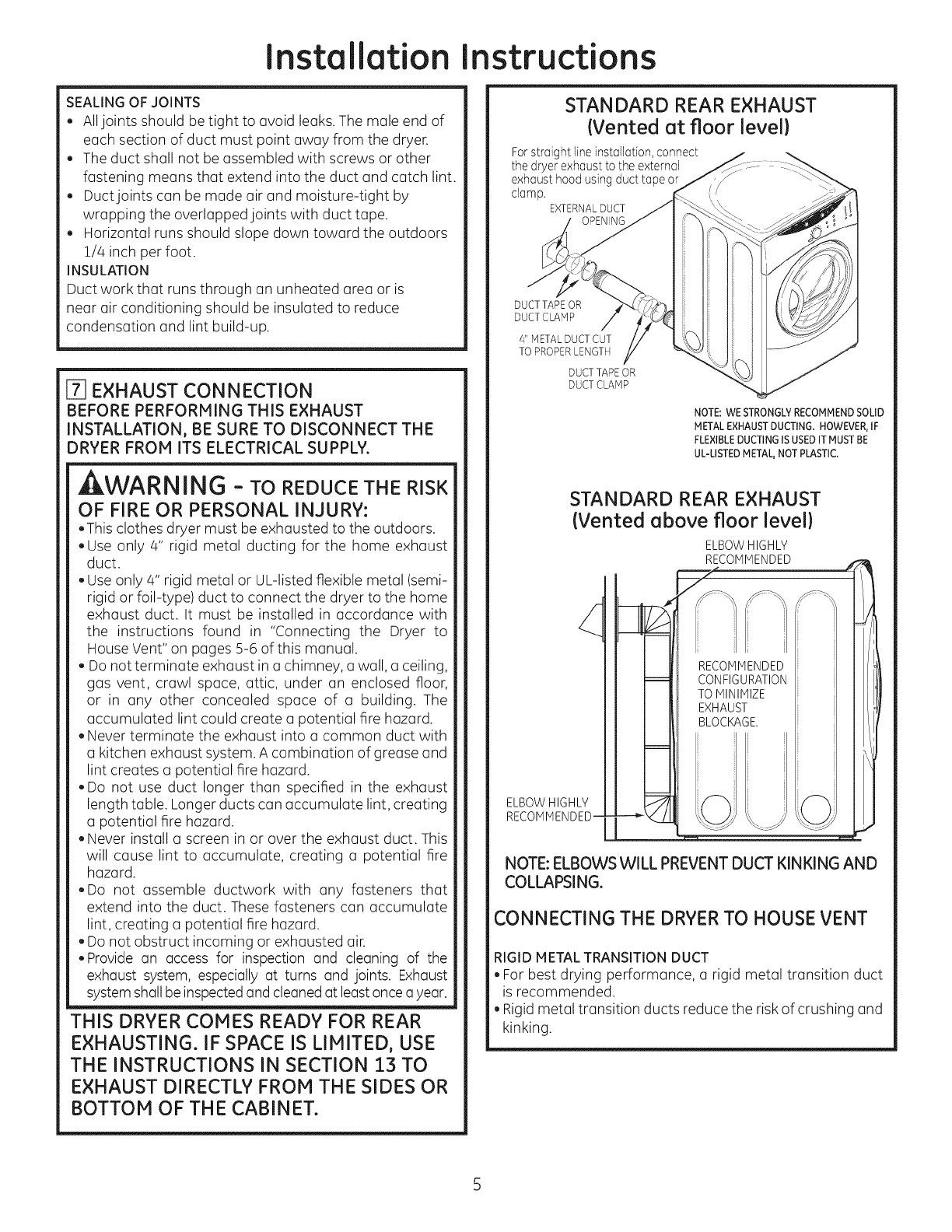
[-7]EXHAUST CONNECTION
BEFORE PERFORMING THIS EXHAUST
INSTALLATION, BE SURE TO DISCONNECT THE
DRYER FROM ITS ELECTRICAL SUPPLY.
WARNING - TO REDUCE THE RISK
OF FIRE OR PERSONAL INJURY:
.This clothes dryer must be exhausted to the outdoors.
.Use only 4" rigid metal ducting for the home exhaust
duct.
. Use only 4" rigid metal or UL-listed flexible metal (semi-
rigid or foil-type) duct to connect the dryer to the home
exhaust duct. It must be installed in accordance with
the instructions found in "Connecting the Dryer to
House Vent" on pages 5-6 of this manual.
. Do not terminate exhaust in a chimney, a wall, a ceiling,
gas vent, crawl space, attic, under an enclosed floor,
or in any other concealed space of a building. The
accumulated lint could create a potential fire hazard.
. Never terminate the exhaust into a common duct with
a kitchen exhaust system. A combination of grease and
lint creates a potential fire hazard.
.Do not use duct longer than specified in the exhaust
length table. Longer ducts can accumulate lint, creating
a potential fire hazard.
. Never install a screen in or over the exhaust duct. This
will cause lint to accumulate, creating a potential fire
hazard.
.Do not assemble ductwork with any fasteners that
extend into the duct. These fasteners can accumulate
lint, creating a potential fire hazard.
. Do not obstruct incoming or exhausted air.
.Provide an access for inspection and cleaning of the
exhaust system, especially at turns and joints. Exhaust
system shall be inspected and cleaned at leastonce ayear.
THIS DRYER COMES READY FOR REAR
EXHAUSTING. IF SPACE IS LIMITED, USE
THE INSTRUCTIONS IN SECTION 13 TO
EXHAUST DIRECTLY FROM THE SIDES OR
BOTTOM OF THE CABINET,
STANDARD REAR EXHAUST
(Vented at floor level}
For straight line installation, connect
the dryer exhaust to the external
exhaust hood using duct tape or
clamp.
EXTERNALDUCT
DUCT TAPE OR
DUCTCLAHP
4" METAL DUCT CUT
TO PROPERLENGTH
DUCT TAPEOR
DUCT CLAMP
NOTE: WE STRONGLYRECOMMENDSOLID
METAL EXHAUSTDUCTING. HOWEVER,IF
FLEXIBLEDUCTING ISUSEDIT MUST BE
UL-LISTEDMETAL,NOT PLASTIC.
ELBOW HIGHLY
RECOIVlIVlENDED-
STANDARD REAR EXHAUST
(Vented above floor level}
ELBOW HIGHLY
RECOMMENDED L
I
TO IVlINIIVlIZE I /
EXHAUST I l,
NOTE: ELBOWS WILL PREVENT DUCT KINKING AND
COLLAPSING.
CONNECTING THE DRYERTO HOUSE VENT
RIGID METALTRANSITION DUCT
. For best drying performance, a rigid metal transition duct
is recommended.
. Rigid metal transition ducts reduce the risk of crushing and
kinking.

Installation instructions
UL-LISTEDFLEXIBLEMETAL(SEMI-RIGID)TRANSITIONDUCT
. If rigid metal duct cannot be used, then UL-listed flexible
metal (semi-rigid) ducting can be used (Kit WX08X!0077).
. Never install flexible metal duct in walls, ceilings, floors or
other enclosed spaces.
. Totallength offlexiblemetalduct should not exceed8feet (2.4m).
. For many applications, installing elbows at both the dryer
and the wall is highly recommended (see illustrations
below). Elbows allow the dryer to sit close to the wall
without kinking and or crushing the transition duct,
maximizing drying performance.
.Avoid resting the duct on sharp objects.
UL-LISTEDFLEXIBLEMETAL(FOIL-TYPE1TRANSITIONDUCT
. In special installations, it may be necessary to connect the
dryer to the house vent using a flexible metal (foil-type) duct.
A UL-listed flexible metal (foil-type) duct may be used ONLY
in installations where rigid metal or flexible metal (semi-rigid)
ducting cannot be used AND where a 4" diameter can be
maintained throughout the entire length of the transition duct.
.In Canada and the United States, only the flexible metal
(foil-type) ducts that comply with the "Outline for Clothes
Dryer Transition Duct Subject 2158A" shall be used.
. Never install flexible metal duct in walls, ceilings, floors or
other enclosed spaces.
. Totallength offlexiblemetalduct should not exceed8feet (2.4m).
. Avoid resting the duct on sharp objects.
For best drying performance:
1. Slide one end of the duct over the clothes dryer outlet pipe.
2. Secure the duct with a clamp.
3. With the dryer in its permanent position, extend the duct
to its full length. Allow 2" of duct to overlap the exhaust pipe.
Cut off and remove excess duct. Keep the duct as straight
as possible for maximum airflow.
4. Secure the duct to the exhaust pipe with the other clamp.
rs ]
ELBOW
REOUIRED
ELBOWS
REOUIRED
LEVELING AND STABILIZING YOUR
DRYER
Stand the dryer upright near the final location and adjust
the 4 leveling legs, at the corners, to ensure that the dryer
is level from side to side and front to rear.
LEVEL LEVEL
FRONT-TO-BACK SIDE-TO-SIDE
4 LEVELING
LEGS
[] ALCOVE OR CLOSET INSTALLATION
. If your dryer is approved for installation in an alcove or
closet, it will be stated on a label on the dryer back.
.The dryer MUST be vented to the outdoors. See the
EXHAUSTINFORMATIONstep 6.
. Minimum clearance between dryer cabinet and adjacent
walls or other surfaces is:
0 in. either side
3in. front
3 in. rear
. Minimum vertical space from floor to overhead cabinets,
ceiling, etc. is 52 in.
.Closet doors must be Iouvered or otherwise ventilated
and must contain a minimum of 60 sq. in. of open area
equally distributed. If the closet contains both a washer
and a dryer, doors must contain a minimum of 120 sq. in.
of open area equally distributed.
.The closet should be vented to the outdoors to prevent
gas pocketing in case of a gas leak in the supply line.
. No other fuel-burning appliance shall be installed in the
same closet with the dryer.
NOTE: WHEN THE EXHAUST DUCT IS LOCATED AT THE
REAROF THE DRYER,MINIMUM CLEARANCE FROM THE
WALL IS5.5 in.
Installation Instructions
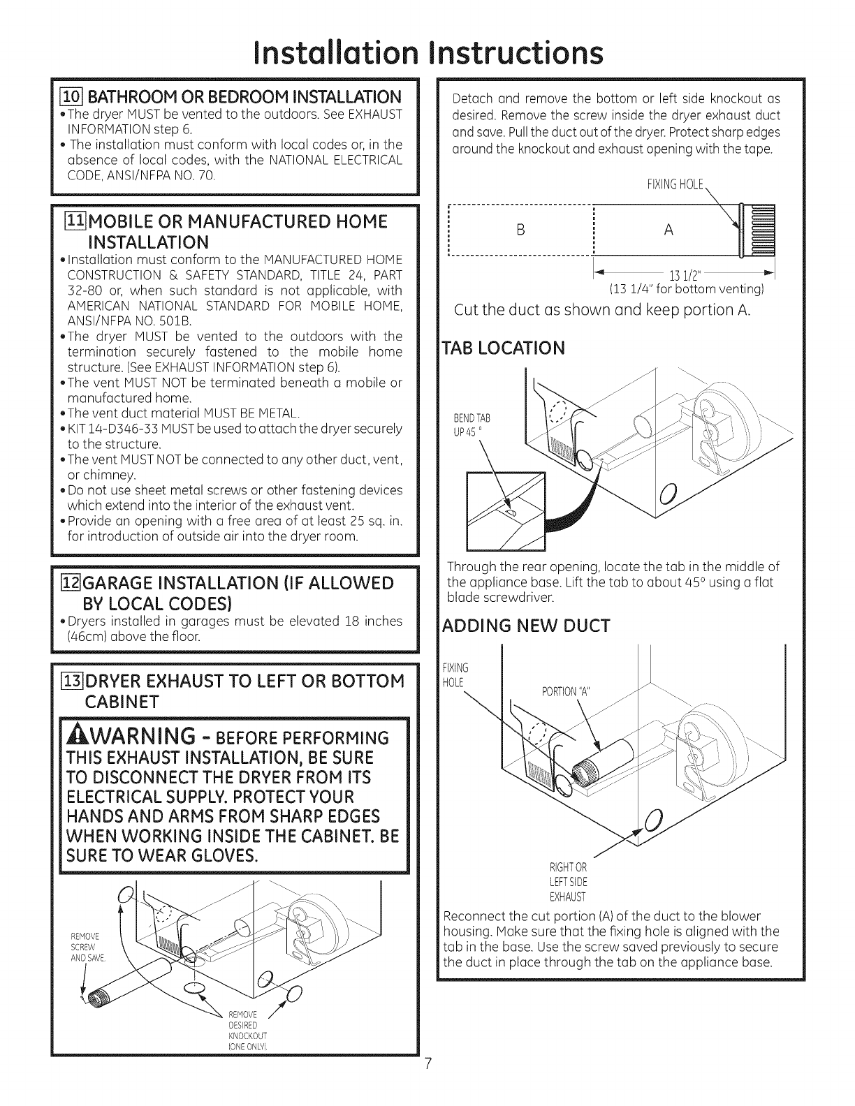
[i-67BATHROOM OR BEDROOM INSTALLATION
.The dryerHUST be ventedtotheoutdoors.See EXHAUST
INFORMATIONstep 6.
. The installation must conform with local codes or, in the
absence of local codes, with the NATIONALELECTRICAL
CODE,ANSI/NFPA NO.70.
[L-_MOBILE OR MANUFACTURED HOME
INSTALLATION
. Installation must conform to the MANUFACTUREDHOME
CONSTRUCTION& SAFETY STANDARD,TITLE 24, PART
32-80 or, when such standard is not applicable, with
AMERICAN NATIONAL STANDARD FOR MOBILE HOME,
ANSI/NFPA NO.501B.
.The dryer MUST be vented to the outdoors with the
termination securely fastened to the mobile home
structure. (SeeEXHAUSTINFORMATIONstep 6).
.The vent MUST NOT be terminated beneath a mobile or
manufactured home.
.The vent duct material MUSTBEMETAL.
. KIT14-D346-33 MUSTbe used to attach the dryer securely
to the structure.
.The vent MUSTNOTbe connected to any other duct, vent,
or chimney.
. Do not use sheet metal screws or other fastening devices
which extend into the interior of the exhaust vent.
. Provide an opening with a free area of at least 25 sq. in.
for introduction of outside air into the dryer room.
[i-27GARAGEINSTALLATION (IF ALLOWED
BY LOCAL CODES)
. Dryers installed in garages must be elevated 18 inches
(a6cm) above the floor.
_-_DRYER EXHAUST TO LEFT OR BOTTOM
CABINET
, WARNING - BEFOREPERFORMING
THIS EXHAUST INSTALLATION, BE SURE
TO DISCONNECT THE DRYER FROM ITS
ELECTRICAL SUPPLY.PROTECTYOUR
HANDS AND ARMS FROM SHARP EDGES
WHEN WORKING INSIDE THE CABINET. BE
SURE TO WEAR GLOVES.
REHOVE
SCREW
AND SAVE
REMOVE
DESIRED
KNOCKOUT
(ONEONW)
Detach and remove the bottom or left side knockout as
desired. Remove the screw inside the dryer exhaust duct
and save. Pullthe duct out of the dryer. Protectsharp edges
around the knockout and exhaust opening with the tape.
FIXINGHOLE_
151/2" m,-
(13 !/4" for bottom venting)
Cut the duct as shown and keep portion A.
TAB LOCATION
BENDTAB
UP45 o
Through the rear opening, locate the tab in the middle of
the appliance base. Lift the tab to about/45 ousing a flat
blade screwdriver.
ADDING NEW DUCT
RIGHTOR
LEFTSIDE
EXHAUST
Reconnect the cut portion (A)of the duct to the blower
housing. Hake sure that the fixing hole is aligned with the
tab in the base. Use the screw saved previously to secure
the duct in place through the tab on the appliance base.
Installation instructions
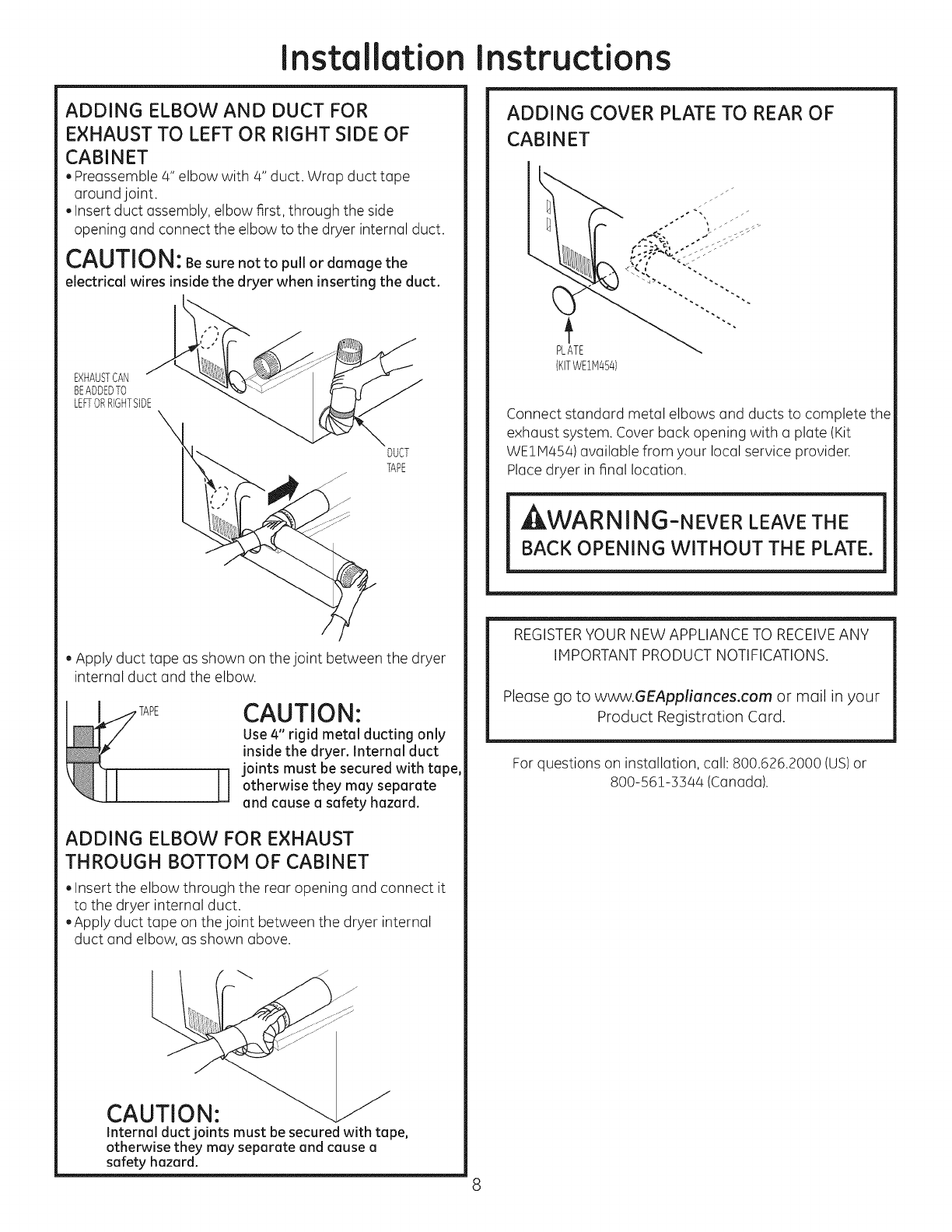
ADDING ELBOW AND DUCT FOR
EXHAUST TO LEFT OR RIGHT SIDE OF
CABINET
, Preassemble 4" elbow with 4" duct. Wrap duct tape
around joint.
. Insert duct assembly, elbow first, through the side
opening and connect the elbow to the dryer internal duct.
CAUTION: Be sure not to pull or damage the
electrical wires inside the dryer when inserting the duct.
EXHAbSTCAN :i _
BEADDEDTO
LEFTORRIGHTSIDE
. Apply duct tape as shown on the joint between the dryer
internal duct and the elbow.
H
CAUTION:
Use 4" rigid metal ducting only
inside the dryer. Internal duct
joints must be secured with tope,
otherwise they may separate
and cause a safety hazard.
ADDING ELBOW FOR EXHAUST
THROUGH BOTTOM OF CABINET
. Insert the elbow through the rear opening and connect it
to the dryer internal duct.
. Apply duct tape on the joint between the dryer internal
duct and elbow, as shown above.
CAUTION:
Internal duct joints must be secured with tape,
otherwise they may separate and cause a
safety hazard.
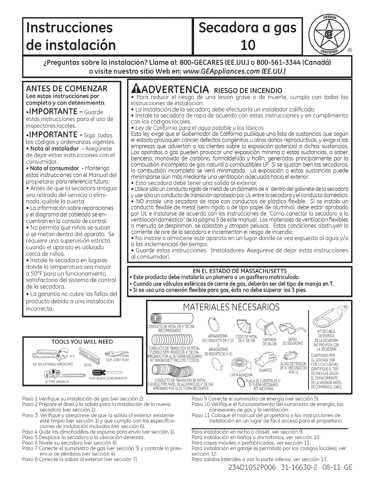
ADDING COVER PLATE TO REAR OF
CABINET
PLATE
{KITWEIM454)
Connect standard metal elbows and ducts to complete the
exhaust system. Cover back opening with a plate (Kit
WEIH454) available from your local service provider.
Place dryer in final location.
_,WARNING-NEVER LEAVE THE
BACK OPENING WITHOUT THE PLATE.
REGISTERYOUR NEW APPLIANCE TO RECEIVEANY
IMPORTANT PRODUCT NOTIFICATIONS.
Please go to www.GEAppliances.com or moil in your
Product Registration Cord.
For questions on installation, call: 800.626.2000 (US)or
800-561-3344 (Canada).
Instrucciones Secadora a gas j(
de instalaci6n
2"Preg un ta s s° borvl_atin:tua/:tci6 :i_iL/a#e_ a/:nSO#w_5 jl_ 3344 {Canadd) I
ANTES DE COMENZAR
Lea estas instrucdones por
completo y con detenimiento.
.IM PORTANTE - Guarde
estas instrucciones para el usa de
inspectores locales.
•IMPORTANTE -sigatodos
losc6digosy ordenanzasvigentes.
. Nora alinstalador-AsegOrese
de dejarestasinstruccionescon el
consumidor.
•Notaalconsumidor-Mantenga
estas instruccionescon el Manual del
propietario para referenciafutura.
• Antes de que la secadora antigua
sea retirada del servicio o elimi-
nada, quitele la puerta.
• Lainformaci6n sabre reparaciones
y el diagrama del cableado se en-
cuentran en la consola decontrol.
• No permita que nihos se suban
o se metan dentro del aparato. Se
requiere una supervisi6n estricta
cuando el aparato es utilizado
cerca de nihos.
• Instale la secadora en lugares
donde la temperatura sea mayor
a 50°F para un funcionamiento
satisfactorio del sistema de control
de la secadora.
. La garantia no cubre las fallas del
producto debido a una instalaci6n
incorrecta.
TOOLS YOU WILL NEED
SLIPJOINTPUEF
10" ADJUSTABLEWRENCHES
FLATBLADESCREWDRIVER
8" PIPEWRENCH
, ADVERTENCIA RIESGO DE INCENDIO
.Para reducir el riesgo de una lesi6n grave o de muerte, cumpla con todas las
instrucciones de instalaci6n.
La instalaci6n de la secadora debe efectuarla un instalador calificado.
Instale la secadora de ropa de acuerdo con estas instrucciones yen cumplimiento
con los c6digos locales.
.Lay de California para el agua potabley los t6xicos
Estaley exige que el Gobernador de California publique una lista de sustancias que segOn
el estado provoquen c@ncer,defectos cong@nitosu otros daflos reproductivos,y exige alas
empresas que adviertan a los clientes sabre la exposici6n potencial a dichas sustancias.
Losaparatos a gas pueden provocar una exposici6n mfnima a estas sustancias,a saber,
benceno, mon6xido de carbono, formaldehfdo y hollfn, generados principalmente par la
combusti6n incompleta de gas natural o combustibles LR Siseajustan bien las secadoras,
la combusti6n incompleta se ver6 minimizada. La exposici6n a estas sustancias puede
minimizarse aOnm6s mediante unaventilaci6n adecuada hacia elexterior.
. Estasecadora debe tener una salida al exterior.
• Utilices61ounconductorfgidodemetaldeundi6metrode4"dentrodelgabinetedelasecadora
y uses61ounconductodetransici6naprobadoparULentrelasecadoray elconductodom@stico.
. NO instale una secadora de ropa con conductos de pl6stico flexible. Si se instala un
conducto flexible de metal (semi rfgido o de tipo papal de aluminio),debe estar aprobado
par ULe instalarse de acuerdo con las instrucciones de "C6mo conectar la secadora a la
ventilaci6n dom@stica"de lap6gina 5 deeste manual. Losmaterialesde ventilaci6n flexibles
a menudo se desploman, se aplastan y atrapan pelusas. Estascondiciones obstruyen la
corriente de aire de la secadorae incrementan el riesgo de incendio.
. No instale o almacene este aparato en un lugar donde se yea expuesto al agua y/o
alas inclemencias del tiempo.
. Guarde estas instrucciones. (Instaladores: AsegOrese de dejar estas instrucciones
al consumidor).
EN ELESTADODE MASSACHUSETTS
• Esteproducto debeinstatarlo un plomero o un gasfltero matricutado.
• Cuandouse v61vulasesf@ricasde cierre de gas,deber(in ser det tipo de manija en T.
• Si se usa una conexi6nflexible para gas, @stano debesuperar los 3 pies.
MATERIALESNECESARIOS
IONDUCTODEMETALDE4"DEDIA
(RECOMENDADO}
ABRAZADERAS
DECONDUCTODE4"(2)
0
CONDUCTODETRANSIClONDEMETAL ABRAZADERAS
FLEXIBLE(SEMIRIGIDO}DE4"DEDIA. , DERESORTEDE4"(2)
_PROBADOPORUL(SIFUERANECESARIOI
KITWXO8XlO077(INCLUYE2CODOS)
%
CODODEMETAL
DE4"DEDIA. CAMPANA GAFAS
DESALIDA DESEGURIDAD
CONDUCTODETRANSICIONDEMETAL
FLEXIBLE(TIPOPAPELDEALUMINIO}DE4"DEDIA.
APROBADOPORUL(SIFUERANECESARIO}
CINTAADHESIVA GUANTES
(KITWE1Mag4}
ALIVIODETENSION
DEsA"RECONOCIDO
PORUL
KITDECABLE
DEENERG/A
DELASECADORA
(NOPROVISTACON
LASECADORA)
CLASIFICADOPOR
UL120/240V,30A
CON30 4CLAVIJAS,
IDENTIFIOUEELTIPO
DEENCHUFEBEGUN
ELTOMACORRIENTE
DELAVIVIENDAANTES
DECOMPRARELCABLE.
Paso !
Paso 2
Paso 3
Paso4
Paso 5
Paso 6
Paso 7
Paso 8
Verifiquesu instalaci6nde gas(versecci6n 2).
Prepareel 6reay lasalida para la instalaci6nde la nueva
secadora(versecci6n 1).
Verifiquey asegOresedeque la salidaal exteriorexistente
est@limpia (versecci6n1)y quecumpla con las especifica-
cionesde instalaci6nincluidas(versecci6n6).
Quitelasalmohadillasdeespumaparaenvio(versecci6n1).
Desplacelasecadoraa la ubicaci6ndeseacta.
Nivelesu secadora(versecci6n8).
Conecteelsuministrode gas(versecci6n3)y controle la pres-
encia dep@rdidas(versecci6n4).
Conectela salidaal exterior(versecci6n7).
Paso 9 Conecte el suministro de energ[a (ver secci6n 5).
Paso 10 Verifique el funcionamiento del suministro de energia, las
conexiones de gas y la ventilaci6n.
Paso 11 Coloque el manual del propietario y las instrucciones de
instalaci6n en un lugar de f6cil acceso para el propietario.
Parainstalaci6nen nicho o closet,ver secci6n9.
Parainstalaci6nen banoso dormitorios,ver secci6n10.
Paracasasm6vileso prefabricadas,ver secci6n11.
Parainstalaci6nen garaje(sipermitido par loscodigoslocales),ver
secci6n 12.
Parasalidaslateraleso par la parte inferior,ver secci6n 13.
234D1052PO06 31-16630-2 08-11 GE

Instrucciones de instalaci6n
Espacio minimo diferente a instalaci6n en nichos o closets.
Losespacioslibresmfnimosrespectodesuperficiescombustiblesydeaberturasdeaireson:Espaciode0 pub. a amboslados,1pub. enel
frentey 3 pulg.enIo portetrosero. Debetenerseencuentounespociolibreodecuodoporounfuncionomientoy reporoci6ncorrectos.
[] PREPARACI6N PARA LA INSTALACI6N
DE UNA SECADORA NUEVA
CONSEJO:Instale su secadora antes de instalar la
lavadora. Esto permitir(_ un mejor acceso cuando
instale la salida de la secadora.
C6HO DESCONECTAR EL GAS
GIRE LA VALVULA ___d_
DEQERRE DE GAS
A LA POSICiON OFF
{APAGADO)
DESCONECTEY ELIMINE
ELCONECTORDE GAS
FLEXIBLEANTIGUO Y
LOS CONDUCTOS VIEJOS.
REEMPLACELOSCON
ADVERTENCIA - NUNCA
VUELVA A USAR CONECTORES
FLE×IBLES GASTADOS.
El uso de conectores flexibles useclos puecle
provocer p@didas de gas y lesiones personales.
Siempre utilice conectores flexibles nuevos cuendo
instale aparatos de gas.
C6HO CUITAR PELUSA DE LA
ABERTURA DE LA SALIDA DE LA PARED
, Quite yclescarte el conclucto de transici6n existente de
plc_sticoo de papel de aluminio ycoloque un conducto
de transici6n aprobado por UL
ABERTURA DE
CONDUCTO INTERNA
PARED
/
VERIFIOUE OUE
EL REGULADOR
DE LA CAI'qPANA
DE SALIDA SEABRA
YCIERRE LIBREMENTE
INCLINE LA SECADORA
DE COSTADO Y QUITE
LAS ALMOHADILLAS
DE ESPUMA PARAENV[O
TOMANDOLAS DE LOS
COSTADOS Y
ARRANCANDOLAS DELAS
PATASDE LA SECADORA.
ASEGORESE DEQUITAR
TODAS LAS PIEZAS
DE ESPUMA UBICADAS
ALREDEDOR DE LAS PATAS.
_-I REQUERIMIENTOS DE GAS
ADVERTENCIA
, La instalaci6n clebecumplir con c6cligos o ordenanzas lo-
cales, o si no las hubiera, con el CODIGONACIONALDEGAS,
ANSIZ223.
Estasecadora a gas estc_equipada con un montaje de
v61vulay quemador para utilizar s61ocon gas natural. Me-
diante el kit de conversi6n WE25X0217,laorganizaci6n de
atenci6n local puede convertir esta secadora para su uso
con gas propano (LP).TODASLASCONVERSIONESDEBEN
LLEVARLASA CABOPERSONALCAPACITADOYCALIFICADO
ENCUMPLIMIENTOCONCODIGOSLOCALESY REq)UERIIVllEN-
TOSDEORDENANZAS.
Lasecadora debe desconectarse del sistema de tuber[a de
suministro de gas durante cualquier prueba de presi6n del
sistema con una presi6n de prueba mayor a 0.5 PSI(3./4KPa).
Lasecadora debe aislarse del sistema de tuber[a de sum-
inistro de gas cerrando la vc_lvulade cierre del equipo
durante cualquier puesta a prueba del sistema en presiones
de prueba iguales o menores a 0.5 PSI(3,a.aKPa).
CONE×I6N DE SUMINISTRO DE GAS DE
LA SECADORA J )
2"
2-5/8" " SUMINISTRO DE GAS ROSCA MACHO NPT DE 3/8"
NOTA:Agregue a la dimensi6n vertical la distancia
entre la porte inferior del gabinete y el piso.
SUMINISTRO DE GAS
, Debe instalarse una toma a rosca de 1/8" NPT,
accesible para una conexi6n del man6metro de prueba,
inmediatamente en sentido ascendente de la conexi6n de
suministro de gas hacia la secadora. Si tiene dudas sobre
la instalaci6n de la toma, comun[quese con su empresa
proveedora de gas local.
La I[nea de suministro debeser de tuber[a r[gida de 1/2"y
debe contar con un cierre accesible dentro de los 6 pies
de la secadora, dentro de la misma habitaci6n donde se
encuentra la misma.
Utilice compuesto sellador para rosca de tuberfa apropiado
para gas natural o LPo utilice cinta deTeflon.
., Una el conector de metal flexible a la secadora y al suminis-
tro de gas.
Abra lavdlvula de cierre.
Con esta secadora debe usarseun conector de metal flexible
(conector aprobado ANSIZ21.2/4/CSA6.10).La Iongitud de la
conexi6n no deber6 superar los 3 pies.
AJUSTE PARA ALTURAS ELEVADAS
,Las clasiflcacionesdeentrada de secadoraspara ropa a gasse
basan en elfuncionamiento a niveldel mar y no debenajustarse
para funcionar a una elevaci6nde 2000 pieso pordebajo de la
misma.Paraun funcionamiento enalturas mayores a 2000pies,
lasclasiflcacionesde entrada deben reducirsea una tasa de 4%
por cada 1000piessobre elniveldel mar.
Lainstalaci6ndebe cumplir con c6digosy ordenanzas
locales,o si nolas hubiera,con el CODIGONACIONALDEGAS
COMBUSTIBLE,ANSIZ223.
Instrucciones de instalaci6n
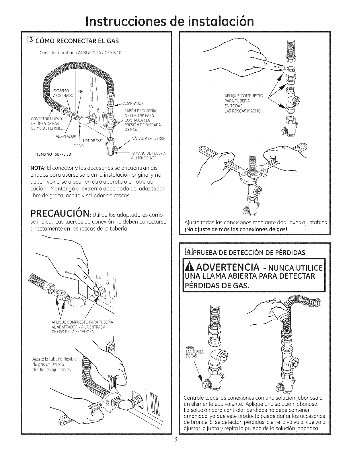
F_C6MO RECONECTAR EL GAS
Conector aprobado ANSI Z21.24 /CSA 6.10
TAPON DETUBER[A
/NPT DE 1/8" PARA
CONECTORNUEVO
DEL[NEADEGAS PRESIONDEENTRADA
DEMETAL FLEXIBLE DEGAS
ADAPTADOR VALVULA DECIERRE
CoDoNPT DE 3/8" j
ITEMSNOT SUPPLIED TAMANO DETUBER[A
AL MENOS 1/2"
NOTA: Elconector y los occesorios se encuentron dis-
e_ados para usorse s61oen la instalaci6n original y no
deben volverse o usor en otro oporoto o en otto ubi-
caci6n, ivlantengo el extremo obocinado del odoptodor
libre de groso, oceite y sellodor de roscos.
f'RC_MU_IVI_: Utilice los adaptadores como
se indica. Las tuercas de conexi6n no deben conectarse
directamente en las roscas de la tuber[a.
APLIQUECOM PU ESTO PARA TU BERiA
AL ADAPTADOR V A LA ENTRADA
DE GAS DE LASECADORA.
Ajustelatuberiaflexible
degasutilizando
dosIlavesajustables.
APLIQUE COMPUESTO
PARA TU BERiA
EN TODAS
LAS ROSCAS MACHO. ©
%
Ajuste todas las conexiones mediante dos Ilaves ajustables.
iNo ajuste de m6s las conexiones de gas!
@PRUEBA DE DETECCI6N DE PI_RDIDAS
ADVERTENCIA - NUNCAUTILICE
UNA LLAMA ABIERTA PARA DETECTAR
PERDIDAS DE GAS.
ABRA
LAVALVULA
DEGAS.
Controle todas las conexiones con una soluci6njabonosa o
un elemento equivalente. Aplique una soluci6njabonosa.
Lasoluci6n para controlar p@didas no debe contener
amonfaco, ya que este producto puede da_ar los accesorios
de bronce. Sise detectan p@rdidas,cierre la v61vula,vuelva a
ajustar lajunta yrepita la prueba de la soluci6n jabonosa.
Instrucciones
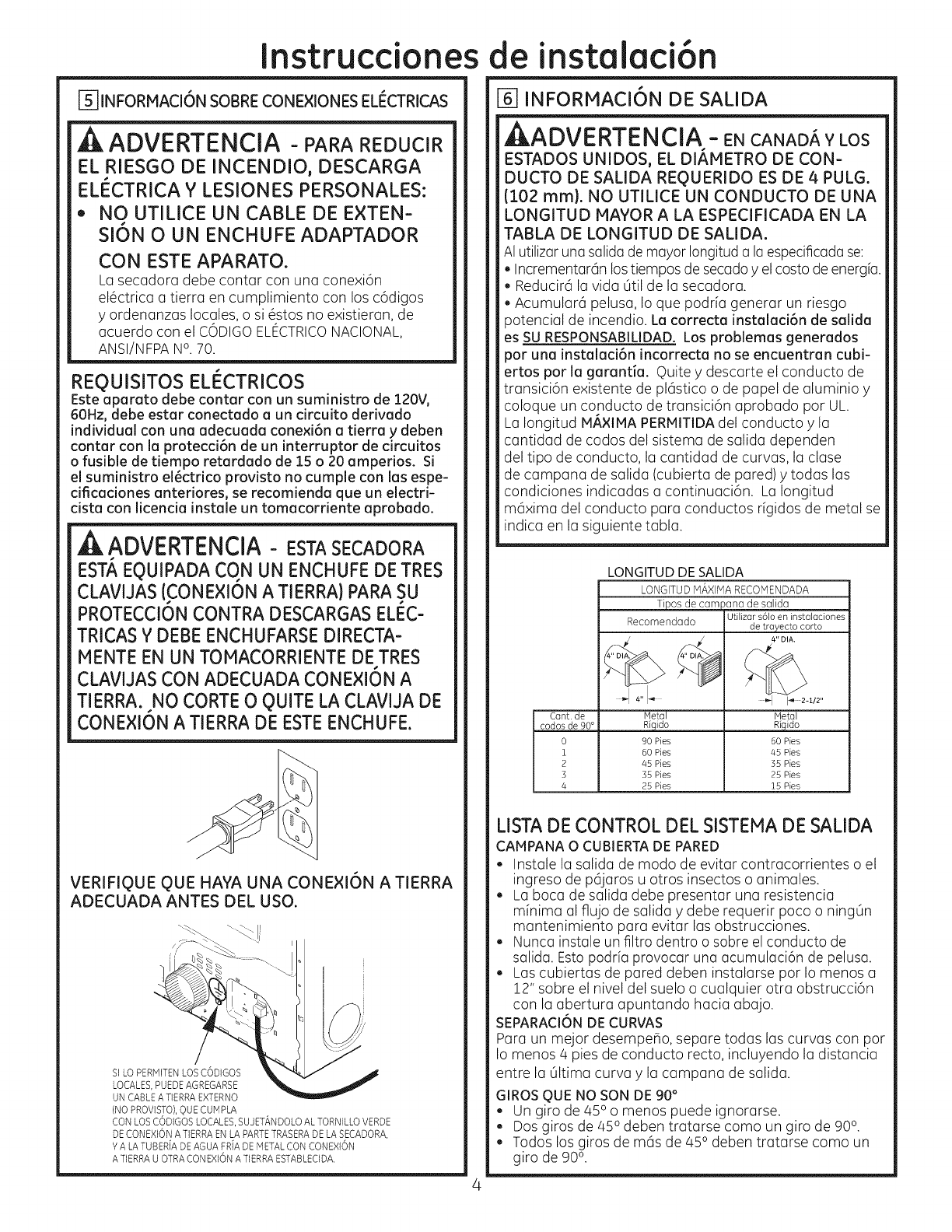
F_INFORMACI6N SOBRE CONEXIONES ELI_CTRICAS
EL RIESGO DE INCENDIO, DESCARGA
ELI_CTRICA Y LESIONES PERSONALES:
• NO UTILICE UN CABLE DE EXTEN-
s
SION 0 UN ENCHUFE ADAPTADOR
CON ESTE APARATO.
Losecadora debe contar con una conexi6n
el6ctrica a tierra en cumplimiento con los c6digos
y ordenanzas locales, o si 6stos no existieran, de
acuerdo con el CODIGO ELECTRICO NACIONAL,
ANSI/NFPA N°. 70.
REQUISITOS ELI_CTRICOS
Este aparato debe contar con un suministro de 120V,
60Hz, debe estar conectado a un circuito derivado
individual con una adecuada conexi6n a tierra y deben
contar con la protecci6n de un interruptor de circuitos
ofusible de tiempo retardado de 15 o 20 amperios. Si
el suministro el_ctrico provisto no cumple con las espe-
cificaciones anteriores, se recomienda que un electri-
cista con licencia instale un tomacorriente aprobado.
ADVERTENCIA - ESTASECADORA
EST', EgUIPADA CON UN ENCHUFE DE TRES
CLAVUAS (CONE×ION A TIERRA) PARA SU
PROTECCION CONTRA DESCARGAS ELEC-
TRICAS Y DEBE ENCHUFARSE DIRECTA-
NENTE EN UN TONACORRIENTE DE TRES
CLAVIJAS CON ADECUADA CONE×ION A
TIERRA. NO CORTE 0QUITE LA CLAVIJA DE
CONEXI6N A TIERRA DE ESTE ENCHUFE.
VERIFIQUE QUE HAYA UNA CONEXI6N A TIERRA
ADECUADA ANTES DEL USO.
SILO PERIVlITENLOSCODIGOS
LOCALES,PUEDEAGREGARSE
UN CABLEA TIERRAEXTERNO
{NO PROVISTO),q)UECUMPLA
CONLOSCODIGOSLOCALES,SUJETANDOLOALTORNILLOVERDE
DECONEXlONA TIERRAEN LA PARTETRASERADELASECADORA,
Y A LATUBER[ADEAGUA FR[ADEMETALCON CONEXlON
A TIERRAU OTRACONEXIONA TIERRAESTABLECIDA.
de instalaci6n
J6JINFORMACI6N DE SALIDA
_I_ADVERTENCIA - EN CANADA Y LOS
ESTADOS UNiDOS, EL DIAHETRO DE CON-
DUCTO DE SALIDA REQUERIDO ES DE 4 PULG.
(102 ram). NO UTILiCE UN CONDUCTO DE UNA
LONGITUD HAVOR A LA ESPECIFICADA EN LA
TABLA DE LONGITUD DE SALIDA.
AI utilizar una salida de mayor Iongituda laespecificada se:
, Incrementar6n los tiempos de secado y el costo de energia.
, Reducir6 la vida 6til de la secadora.
, Acumular6 pelusa, Io que podria generar un riesgo
potencial de incendio. La correcta instalaci6n de salida
es SU RESPONSABILIDAD. Los problemas generados
por una instalaci6n incorrecta no se encuentran cubi-
ertos por la garantia. Quite y descarte el conducto de
transici6n existente de pl6stico o de papel de aluminio y
coloque un conducto de transici6n aprobado por UL.
La Iongitud MAXIMA PERHITIDA del conducto y la
cantidad de codos del sistema de salida dependen
del tipo de conducto, la cantidad de curvas, la clase
de campana de salida (cubierta de pared) y todas las
condiciones indicadas a continuaci6n. La Iongitud
m6xima del conducto para conductos r[gidos de metal se
indica en la siguiente tabla.
Cant. de
codas de 90 °
0
i
2
3
4
LONGITUD DE SALIDA
LONGITUD MAXIMA RECOMENDADA
Tipos de campana de salida
Recomendado
Hetal
Rigido
90 Pies
60 Pies
45 Pies
35 Pies
25 Pies
Utilizar s61o en instalaciones
de trayecto corto
4" DIA.
Hetal
Rigido
60 Pies
45 Pies
55 Pies
25 Pies
15 Pies
LISTADE CONTROL DEL SISTEMA DE SALIDA
CAMPANA 0 CUBIERTA DE PARED
, Instale la salida de modo de evitar contracorrientes o el
ingreso de p6jaros u otros insectos o animales.
, La boca de salida debe presentar una resistencia
minima al flujo de salida y debe requerir poco o ning6n
mantenimiento para evitar las obstrucciones.
, Nunca instale un filtro dentro o sobre el conducto de
salida. Esto podria provocar una acumulaci6n de pelusa.
, Las cubiertas de pared deben instalarse pot Io menos a
!2" sobre el nivel del suelo o cualquier otra obstrucci6n
con la abertura apuntando hacia abajo.
SEPARACION DE CURVAS
Para un mejor desempeho, separe todas las curvas con por
Io menos/4 pies de conducto recto, incluyendo la distancia
entre la 61tima curva y la campana de salida.
GIROS QUE NO SON DE 90 °
. Un giro de a,50o menos puede ignorarse.
. Dos giros de 45odeben tratarse como un giro de 90°.
. Todos los giros de m6s de 45° deben tratarse como un
giro de 90°.
Instrucciones de
SELLADO DE JUNTAS
, Todaslasjuntas deben estar bien selladaspara evitar
pGrdidas. Elextremo macho de cada secci6n de conducto
debe apuntar en direcci6n opuesta a la secadora.
, Elconclucto no deber6 instalarse con tornillos u otros
medios de sujeciGn que se extienclan clentro clel
conclucto y enganchen pelusas.
Lasjuntas de los conductos cleben ser hermGticas al aire
y a la humeclad mecliante la superposiciGn clejuntas con
cinta aislante o cinta de aluminio.
Los tramos horizontales deben tener una inclinaciGn
hacia el exterior de 1/4" por pie.
AISLACI6N
Los conductos instalados a trav6s de un 6rea sin calefacci6n
o ubicados cerca de un acondicionador de aire deben aislarse
para reducir la condensaci6n yla acumulaci6n de pelusas.
i-7] CONE×IGN A LA SALIDA
ANTES DE EFECTUAR ESTA INSTALACIGN DE
SALIDA0 ASEGURESE DE DESCONECTAR LA
SECADORA DEL SUMINISTRO ELECTRICO.
AADVERTENCIA - PARAREDUCIR
EL RIESGO DE INCENDIO O DE LESIONES
PERSONALES:
, Esta secadora de ropa debe tener una salida al exterior.
, Utilice sGIo un conclucto de metal r[gido de 4" para el
conducto de salida domGstico.
,Use sGIo un conducto de metal r[gido de 4" o de
metal flexible (semi r[gido o de tipo papel de aluminio)
aprobaclo pot UL para conectar la secaclora al conducto
de salicla domGstico. Debe instalarse de acuerclo con las
instrucciones incluidas en "CGmo conectar la secadora
a la ventilaciGn domGstica" de las pGginas 5-6 de este
manual.
, No instale la boca de salida dentro de una chimenea,
pared, cielorraso, ventilaciGn de gas, espacio entre pisos,
6tico, bajo un piso con cerramiento o en cualquier otro
espacio oculto de un eclificio. La acumulaciGn de pelusas
podr[a provocar un riesgo potencial de incenclio.
, Nunca instale la boca de salida clentro de un conclucto
comL_n con el sistema de salicla de la cocina. La
combinaciGn de grasa y pelusas podr[a provocar un
riesgo potencial de incenclio.
,No utilice un conclucto de una Iongitucl mayor a la
especificada en la tabla de Iongitud de salida. Los
conductos rags largos acumulan pelusa, Io que genera
un riesgo potencial de incendio.
, Nunca instale un filtro clentro o sobre el conclucto de
salida. Esto provocar6 la acumulaciGn de pelusas, Io que
genera un riesgo potencial de incendio.
No arme la red de conductos con sujeciones que se
extiendan dentro del conducto. Estas sujeciones pueden
acumular pelusa, Io que genera un riesgo potencial de
incendio.
No obstruya el aire que entra y sale.
Incluya un acceso para inspecciGn y limpieza del sistema
de salida, especialmente en las curvas y juntas. El
sistema de salida debe inspeccionarse y limpiarse por Io
menos una vez al aho.
ESTA SECADORA VIENE LISTA PARA UTILIZAR UNA
SALIDA POR LA PARTE TRASERA. SI EL ESPACIO ES
LIMITA.DO, UTILICE LAB INSTRUCCIONES DE LA
SECCION 13 PARA UNA SALIDA DIRECTA DESDE LOS
LADOS O PARTE INFERIOR DEL GABINETE.
instalaci6n
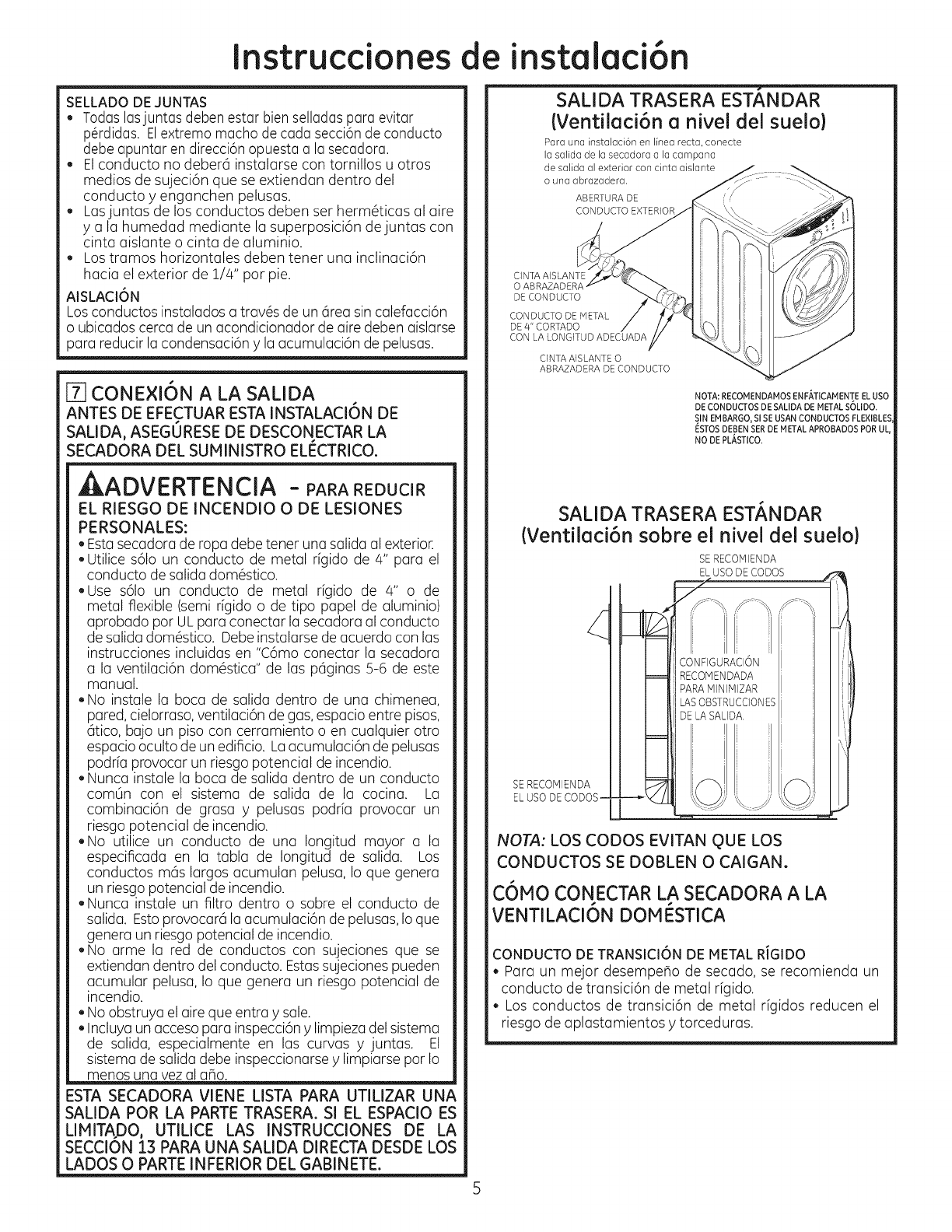
SALIDA TRASERA ESTANDAR
(VentilaciGn a nivel del suelo)
Para una instalaciGn en linea recta, conecte
iasaiidadeiasecadoraa iacampana
desalidaaiexteriorconcintaaisiante
o una abrazadera.
ABERTURA DE
CONDUCTO EXTERIOR
CINTA AISLANTE
O
DE CONDUCTO
CONDUCTO DE METAL
DE 4" CORTADO
CON LA LONGITUD ADECUADA
CINTA AISLANTE O
ABRAZADERA DE CONDUCTO
NOTA: RECOMENDAMOS ENFATICAM ENTE EL USO
DE CONDUCTOS DE BALIDA DE METAL S6LIDO.
SIN EMBARGO, Sl SE USAN CONDUCTOS FLEXlBLES
ESTOSDEBEN SERDE METAL APROBADOS POR UL,
NO DE PLASTICO.
SALIDA TRASERA EST/_NDAR
(VentilaciGn sobre el nivel del suelo)
SE RECOPqlENDA
SE RECOMIENDA
ELUSO DECODOS-
NOTA: LOS CODOS EVITAN QUE LOS
CONDUCTOS SE DOBLEN O CAIGAN°
C6MO CONECTAR LA SECADORA A LA
VENTILACI6N DOMI_STICA
CONDUCTO DE TRANSICI6N DE METAL RIGIDO
• Para un mejor desempeflo de secado, se recomienda un
conducto de transici6n de metal rfgido.
• Los conductos de transici6n de metal rfgidos reducen el
riesgo de aplastamientos ytorceduras.
Instrucciones de instalaci6n
CONDUCTODE TRANSICI6N DE METALFLEXIBLE
(SEMI-RiGIDO)APROBADOPOR UL
. Si no puede utilizarse un conducto de metal rfgido, entonc-
es puede usarse un conducto de metal fexible (semi-r[gido)
aprobado par UL (Kit WX08XZ0077).
. Nunca instale conductos de metal flexibles en paredes,
cielorrasos, pisos u otros espacios cerrados.
. La Iongitud total del conducto de metal flexible no deber6
superar los 8 pies (2./4m).
.Para muchas aplicaciones, se recomienda enfdticamente la
instalaci6ndecodasenlasecadorayen la pared(verilustraciones
de abajo).Los codas permiten que la secadorase ubique cerca
de la pared sin torcer o aplastar elconducto detransici6n,Io que
potenciaal mdximoel desempehode secado.
. No coloque el conducto sabre objetos afilados.
CONDUCTODE TRANSICI6NDE METALFLEXIBLE(SEMI-RIGIDO)
APROBADOPORUL
. En instalaciones especiales, puede ser necesario conectar la
secadora a la ventilaci6n dom6stica utilizando un conducto
de metal flexible (tipo papal de aluminio). Puede utilizarse un
conductode metal flexible (tipo papal de aluminio) aprobado
par UL SOLOen instalaciones en los que no pueden usarse
conductos de metal rfgidos o flexibles (semi-rfgidos) Yen los
que puede mantenerse un di6metro de 4" a Io largo de todo
el conducto de transici6n.
.En Canad6 ylos Estados Unidos, solamente deber6n
utilizarse los conductos de metal flexibles (tipo papel de
aluminio) que cumplan con el "Resumen para conductos de
transici6n para secadoras de ropa, Tema 2158A".
.Nunca instale conductos de metal flexibles en paredes,
cielorrasos, pisos u otros espacios cerrados.
. La Iongitud total del conducto de metal flexible no deber6
superar los 8 pies (2./4m).
. No coloque el conducto sabre objetos afilados.
Para un mejor desempeho de secado:
1. Deslice un extremo del conducto sabre la tuberfa de salida
de la secadora de ropa.
.Fije el conducto con una abrazadera.
. Con la secadora en su posici6n permanente, extienda el
conducto en su Iongitud total. Deje qua se superpongan 2"
de conducto con la tuberfa de salida. Carte yquite el tramo
de conducto qua sabre. Mantenga el conducto Io m6s recto
posible para Iograr una corriente de aire m6xima.
4. Fijeel conducto ala tuberfa de salida con la otra abrazadera.
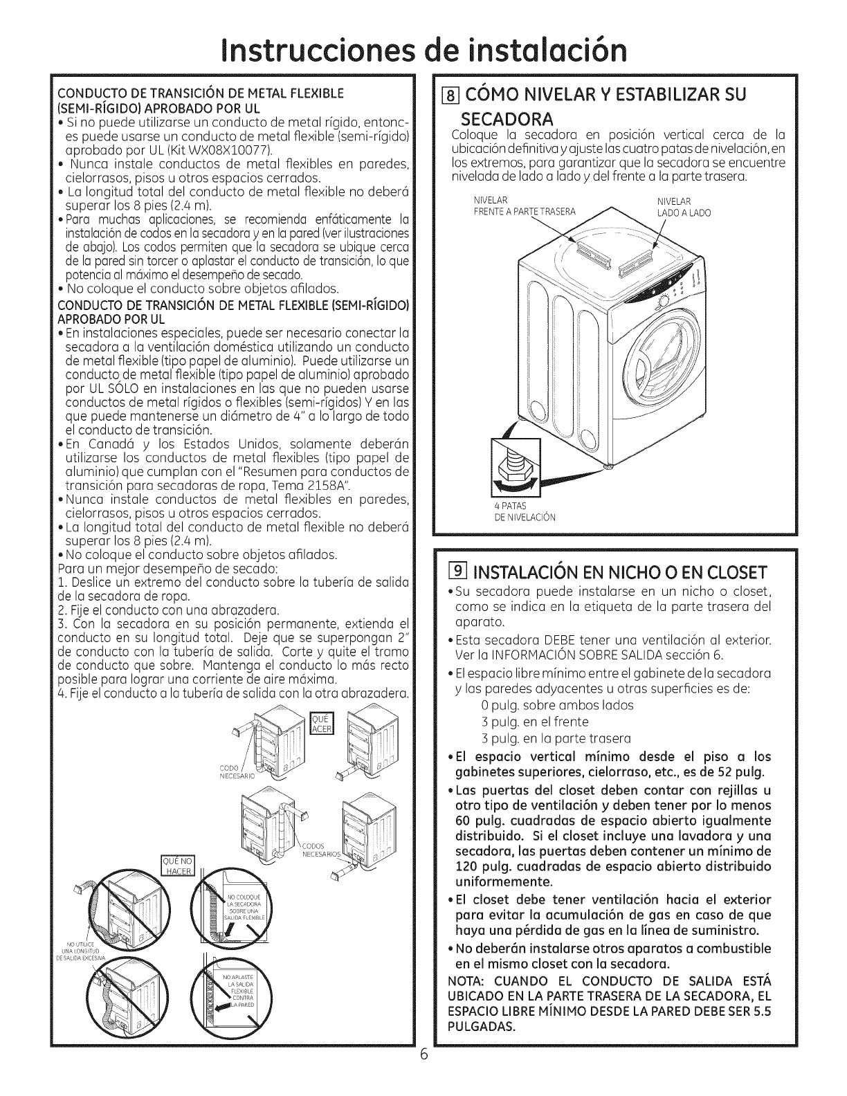
C6MO NIVELAR Y ESTABILIZAR SU
SECADORA
Coloque la secadora en posici6n vertical cerca de la
ubicaci6n definitiva yajuste loscuatro patas de nivelaci6n, en
los extremos, para garantizar que la secadora se encuentre
nivelada de lado a lado ydel frente a la porte trasera.
NIVELAR NIVELAR
FRENTEA PARTETRASERA LADO A LADO
4 PATAS
DENIVELACION
INSTALACI6N EN NICHO O EN CLOSET
.Su secadora puede instalarse en un nicho o closet,
coma se indica en la etiqueta de la parte trasera del
aparato.
. Esta secadora DEBEtenet una ventilaci6n al exterior.
Vet la INFORMACIONSOBRESALIDAsecci6n 6.
. Elespacio libre minima entre el gabinete de la secadora
y las paredes adyacentes u otras superficies es de:
0 pulg. sabre ambos lados
3 pulg. en el frente
3 pulg. en la parte trasera
.El espacio vertical minima desde el piso a los
gobinetes superiores, cielorraso, etc., es de 52 pulg.
, Los puertos del closet deben cantor con rejillas u
otro tipo de ventilaci6n y deben tener par Io menos
60 pulg. cuadrados de espacio abierto iguolmente
distribuido. Si el closet incluye una lavodora y una
secadoro, los puertos deben contener un minima de
120 pulg. cuodrodos de espocio abierto distribuido
uniformemente.
.El closet debe tener ventilod6n hocio el exterior
poro evitor Io ocumuloci6n de gas en caso de qua
hoyo una p6rdida de gas en Io linea de suministro.
. No deber6n instolorse otros oparotos a combustible
en el mismo closet con Io secodoro.
NOTA: CUANDO EL CONDUCTO DE SALIDA EST#,
UBICADO EN LA PARTETRASERADE LA SECADORA,EL
ESPACIOLIBREMiNIMO DESDELA PAREDDEBESER5.5
PULGADAS.

Instrucciones de
[_ INSTALACIeN EN BAIIOS O
DORHITORIOS
• Estasecadora DEBEtener una ventilaci6n al exterior. Ver la
INFORtVlACIONSABRESALIDAsecci6n6.
• Lainstalaci6ndebecumplircon c6digoslocaleso,sinoexistieran,
con elCODIGOELECTRICONAGONAL,ANS@NFPANO70.
F_INSTALACION EN CASAS IvIOVILES O
PREFABRICADAS
*Lainstalaci6ndebecumplirconlaNORHASABRECONSTRUCCt0N
Y SEGURtDADDE CASASPREFABRtCADAS,TITULO24, PARTE
32-80 o, cuando dicha norma no sea aplicable,con la NORHA
NACtONALESTADOUNtDENSEPARACASASHOVtLES,ANSt/NFPA
NO501B.
*La secadora DEBE tener ventilaci6n al exterior con la
terminaci6n biensujetaa la estructurade la casam6vil. (Verla
tNFORHACt0NSABRESALtDA,secci6n6).
*La ventilaci6n NO DEBEterminar debajo de una casa m6vil o
prefabricada.
*Elmaterialdel conducto deventilaci6n DEBESERHETAL
,DEBEutilizarseel KIT:].4-D346-33paraconectar bienlasecadora
a la estructura.
,La ventilaci6n NO DEBEconectarse a ningOnotto conducto,
ventilaci6no chimenea.
,No utilice tornillos para placasde metal u otros dispositivosde
sujeci6nque seextiendanal interior de laventilaci6n de salida.
,Debecontar con una abertura con un espacio libre de par Io
menos 25 pulgadascuadradas para el ingreso de aire exterior
dentro del cuarto dela secadora.
j-f2]INSTALACleN EN GARAJE (SI PERMITI-
DO PaR LOS CODIGOS LOCALES)
, Secadoras instaladas en garages deben ser
elevadas 18 pulgadas (46cm) del nivel del piso.
[]SALIDA DE LA SECADORA HACIA LA
IZQUIERDA O PARTE INFERIOR DEL
GABINETE
EFECTUARESTAINSTALACI6N DE SALIDA,
ASEGURESEDE DESCONECTARLA SECADORA
DELSUMINISTROELECTRICO.PROTEJASUS
PIANOSY BRAZOSDE LOSLADOSAFILADOS
CUANDO TRABAJEDENTRODELGABINETE.
ASEGURESEDE USARGUANTES.
OUITE EL
TORNILLO
Y CONSERVEL
QUITE ,/_
EL RECORTE
DESEADO (SOLO UNO)
Despegue yquite el recorte inferior, derecho o izquierdo,
segOn corresponda. Quite el tomfllo ubicado dentro
del conducto de salida de la secadora ycons6rvelo
Saque el conducto de ia secadora
instalaci6n
Despegue yquite el recorte inferior o izquierdo, seg0n
correspondo. Quite eltomillo ubicudo dentro del conducto
de solida de Io secodoro ycons@velo. Soque el conducto
de Io secadoro. Proteja los bordes ofilodos del recorte yde
Io oberturo de Io solido con cinto. ORIFICIODEIVlONTAJE
X
AN
J_ 13 i/2"
(13 1/4" para ventilaci6n inferior)
Carteelconducto coma puedeverseL_conservela porci6n A
UBICACI6N DE LA LENGUETA
GIRE LA LENGOETA
HASTA 45 °
A trav6s de la abertura trasera, ubique la lengOeta en
el medio de la base del aparato. Levante la leng@eta
hasta alrededor de/45°, utilizando un destornillador de
lados pianos.
C6MO AGREGAR CONDUCTOS NUEVOS
ORIFICIO I
DE HONTAJE
PORCION "A"
SALIDA LATERAL
PaR DERECHA O IZQUIERDA
Vuelva a conectar la porci6n cortada (A)del conducto a la
carcasa del ventilador. Aseg6rese de que el conducto m6s
corto se encuentre alineado con la leng@etade la base.
Utilice el tornillo conservado con anterioridad para sujetar
el conducto en su lugar a trav6s de la leng@etade la base
del artefacto.
Instrucciones de instalaci6n
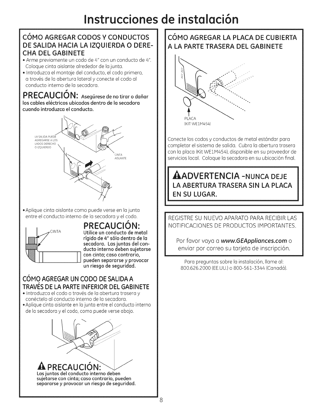
COMO AGREGAR CODOS Y CONDUCTOS
DE SALIDA HACIA LA IZQUIERDA O DERE-
CHA DEL GABINETE
. Arme previamente un coda de 4" con un conducto de 4".
Coloque cinta aislante alrededor de lajunta.
Introduzca el montaje del conducto, el coda primero,
a trav6s de la abertura lateral y conecte el codo al
conducto interno de la secadora.
s
PRECAUCION: Aseg6rese de no tirar o da_ar
loscablesel_ctricosubicadosdentrode lasecadora
cuando introduzcaelconducto.
CFNTA
/'_ AISLANTE
,Aplique cinta aislante coma puede verse en la junta
entre el conducto interno de la secadora yel coda.
s
PRECAUCION:
Utilice un conducto de metal
rigido de 4" s61odentro de la
secadora. Lasjuntas del con-
ducto interno deben sujetarse
]]con cinta; caso contrario,
pueden separarse y provocar
un riesgo de seguridad.
C6MO AGREGARUN CODO DE SALIDAA
TRAVI_SDE LA PARTEINFERIORDELGABINETE
. Introduzca el coda a tray,s de la abertura trasera y
con6ctelo al conducto interno de la secadora.
,Aplique cinta aislante en lajunta entre el conducto interno
de la secadora yel coda, coma puede verse abajo.
k
A PRECAUCI6N:
Lasjuntasdelconductointernodeben
sujetarsecon cinta;casocontrario,pueden
separarsey provocarun riesgode seguridad.
C6MO AGREGAR LA PLACA DE CUBIERTA
A LA PARTE TRASERA DEL GABINETE
q%,, "-.
PLACA
(KIT WE 11v1454)
Conecte los codas y conductos de metal est6ndar para
completar el sistema de salida. Cubra la abertura trasera
con la placa (Kit WE11V1454),disponible en su proveedor de
servicios local. Coloque la secadora en su ubicaci6n final.
AADVERTENCIA -NUNCA DEJE
LA ABERTURA TRASERA SIN LA PLACA
EN SU LUGAR.
REGISTRE SU NUEVO APARATO PARA RECIBIR LAS
NOTIFICACIONES DE PRODUCTOS IMPORTANTES.
Par favor vaya a www.GEAppliances.com o
enviar par correo su tarjeta de inscripci6n.
Para preguntas sabre la instalaci6n, Ilame al:
800.626.2000 (EE.UU.)o 800-561-3344 (Canad6).
