GE GFK 1918D FXVersaPro User Manual To The E757f124 6f65 4350 95e4 E4d1ba01ef74
User Manual: GE GFK-1918D to the manual
Open the PDF directly: View PDF ![]() .
.
Page Count: 114 [warning: Documents this large are best viewed by clicking the View PDF Link!]

Getting Started
May 2003
Version 4.00
GFK-1918D
Logic Developer - PLC
PLC Programming Software

2
All rights reserved. No part of this publication may be reproduced in any form or by
any electronic or mechanical means, including photocopying and recording,
without permission in writing from GE Fanuc Automation Americas, Inc..
Disclaimer of Warranties and Liability
The information contained in this manual is believed to be accurate and reliable.
However, GE Fanuc Automation Americas, Inc. assumes no responsibilities for any
errors, omissions or inaccuracies whatsoever. Without limiting the foregoing, GE
Fanuc Automation Americas, Inc. disclaims any and all warranties, expressed or
implied, including the warranty of merchantability and fitness for a particular
purpose, with respect to the information contained in this manual and the
equipment or software described herein. The entire risk as to the quality and
performance of such information, equipment and software, is upon the buyer or
user. GE Fanuc Automation Americas, Inc. shall not be liable for any damages,
including special or consequential damages, arising out of the use of such
information, equipment and software, even if GE Fanuc Automation Americas, Inc.
has been advised in advance of the possibility of such damages. The use of the
information contained in the manual and the software described herein is subject to
GE Fanuc Automation Americas, Inc. standard license agreement, which must be
executed by the buyer or user before the use of such information, equipment or
software.
Notice
GE Fanuc Automation Americas, Inc. reserves the right to make improvements to the
products described in this publication at any time and without notice.
© 2003 GE Fanuc Automation Americas, Inc. All rights reserved. CIMPLICITY is a
registered trademark of GE Fanuc Automation. Any other trademarks referenced
herein are used solely for purposes of identifying compatibility with the products of
GE Fanuc Automation Americas, Inc.
We want to hear from you. If you have any comments, questions, or suggestions
about our documentation, send them to the following email address:
doc@gefanuc.com

CIMPLICITY Logic Developer - PLC Version 4.00 i
Contents
1 Welcome 1
System Requirements . . . . . . . . . . . . . . . . . . . . . . . . . . . . . . . . . . .3
Installation . . . . . . . . . . . . . . . . . . . . . . . . . . . . . . . . . . . . . . . . . . .4
Product Authorization . . . . . . . . . . . . . . . . . . . . . . . . . . . . . . . . . . .5
Technical Support . . . . . . . . . . . . . . . . . . . . . . . . . . . . . . . . . . . . . .7
2 CIMPLICITY Machine Edition 9
Quick Start . . . . . . . . . . . . . . . . . . . . . . . . . . . . . . . . . . . . . . . . . .10
Projects . . . . . . . . . . . . . . . . . . . . . . . . . . . . . . . . . . . . . . . . . . . . .12
Tools . . . . . . . . . . . . . . . . . . . . . . . . . . . . . . . . . . . . . . . . . . . . . . .14
Variables . . . . . . . . . . . . . . . . . . . . . . . . . . . . . . . . . . . . . . . . . . . .16
Options . . . . . . . . . . . . . . . . . . . . . . . . . . . . . . . . . . . . . . . . . . . . .19
Machine Edition Help . . . . . . . . . . . . . . . . . . . . . . . . . . . . . . . . . .20
Companion Help . . . . . . . . . . . . . . . . . . . . . . . . . . . . . . . . . . .20
InfoViewer Help . . . . . . . . . . . . . . . . . . . . . . . . . . . . . . . . . . .20
3 GE Fanuc PLC Targets 23
Addinging, Configuring and Converting Targets . . . . . . . . . . . . . .24
Adding Targets . . . . . . . . . . . . . . . . . . . . . . . . . . . . . . . . . . . .24
Configuring Targets . . . . . . . . . . . . . . . . . . . . . . . . . . . . . . . .25
Converting Targets . . . . . . . . . . . . . . . . . . . . . . . . . . . . . . . . . .26
Configuring Communication . . . . . . . . . . . . . . . . . . . . . . . . . . . . .28
Configuring Communication for PACSystems™ . . . . . . . . . . . .28
Configuring Communication for non-PACSystems™ PLCs . . . .30
Interacting with the PLC . . . . . . . . . . . . . . . . . . . . . . . . . . . . . . . .33
Validating a Target . . . . . . . . . . . . . . . . . . . . . . . . . . . . . . . . .33
Online/Offline . . . . . . . . . . . . . . . . . . . . . . . . . . . . . . . . . . . . .33
Upload/Download . . . . . . . . . . . . . . . . . . . . . . . . . . . . . . . . . .35
Run/Stop . . . . . . . . . . . . . . . . . . . . . . . . . . . . . . . . . . . . . . . . .36
Fault Tables . . . . . . . . . . . . . . . . . . . . . . . . . . . . . . . . . . . . . . .37
Reference View Tables . . . . . . . . . . . . . . . . . . . . . . . . . . . . . .38
Reports . . . . . . . . . . . . . . . . . . . . . . . . . . . . . . . . . . . . . . . . . .40

ii CIMPLICITY Logic Developer - PLC Version 4.00
4 Hardware Configuration (HWC) 43
PACSystems™ RX7i . . . . . . . . . . . . . . . . . . . . . . . . . . . . . . . . 43
Configuring PACSystems™ RX7i Hardware . . . . . . . . . . . . . . 44
Redundancy (Series 90™-70 and PACSystems™ RX7i only) . . 50
Configuring Redundant Systems . . . . . . . . . . . . . . . . . . . . . . . 52
Series 90™-30: DSM314 Motion Module . . . . . . . . . . . . . . . . 55
Series 90™-70 Genius Remote I/O Scanner . . . . . . . . . . . . . . 57
VersaMax Remote I/O . . . . . . . . . . . . . . . . . . . . . . . . . . . . . . . 59
5 Logic Editors 63
LD Editor . . . . . . . . . . . . . . . . . . . . . . . . . . . . . . . . . . . . . . . . . . . 66
Working with the LD Editor Offline . . . . . . . . . . . . . . . . . . . . 67
Editing Logic as Text . . . . . . . . . . . . . . . . . . . . . . . . . . . . . . . . 70
Working with the LD Editor Online . . . . . . . . . . . . . . . . . . . . 72
Word-for-Word Changes . . . . . . . . . . . . . . . . . . . . . . . . . . . . 73
Writing Changes to a Target PLC . . . . . . . . . . . . . . . . . . . . . . 74
LD Functions . . . . . . . . . . . . . . . . . . . . . . . . . . . . . . . . . . . . . 75
IL Editor . . . . . . . . . . . . . . . . . . . . . . . . . . . . . . . . . . . . . . . . . . . . 79
Working with the IL Editor Offline . . . . . . . . . . . . . . . . . . . . . 80
Working with the IL Editor Online . . . . . . . . . . . . . . . . . . . . . 82
Writing Changes to a Target PLC . . . . . . . . . . . . . . . . . . . . . . 83
IL Instructions and Functions . . . . . . . . . . . . . . . . . . . . . . . . . 84
C Blocks . . . . . . . . . . . . . . . . . . . . . . . . . . . . . . . . . . . . . . . . . . . . 86
Working with C blocks . . . . . . . . . . . . . . . . . . . . . . . . . . . . . . 86
C Programs . . . . . . . . . . . . . . . . . . . . . . . . . . . . . . . . . . . . . . . . . 88
User Programs . . . . . . . . . . . . . . . . . . . . . . . . . . . . . . . . . . . . 88
Working with User Programs . . . . . . . . . . . . . . . . . . . . . . . . . 89
6 Motion Programming 91
PLC Motion Editor . . . . . . . . . . . . . . . . . . . . . . . . . . . . . . . . . . . . 92
Working with the Motion Editor . . . . . . . . . . . . . . . . . . . . . . . 93
Motion Commands . . . . . . . . . . . . . . . . . . . . . . . . . . . . . . . . . 94
Local Logic . . . . . . . . . . . . . . . . . . . . . . . . . . . . . . . . . . . . . . . . . 95
Working with Local Logic Editor . . . . . . . . . . . . . . . . . . . . . . . 96
Local Logic Variables . . . . . . . . . . . . . . . . . . . . . . . . . . . . . . . 97
Local Logic Commands and Operators . . . . . . . . . . . . . . . . . . 99


CIMPLICITY Logic Developer - PLC Version 4.00 1
1
Welcome
Congratulations on your purchase of Logic Developer - PLC, the GE Fanuc PLC
programming component of Machine Edition automation software. This software
package provides all the tools necessary to create powerful control applications.
Logic Developer - PLC provides a way to configure your PLC hardware or remote
I/O, create and edit PLC logic, upload and download projects, and monitor and
debug the execution of control programs. Projects can be imported from
Logicmaster, VersaPro, and CimplicityControl folders.

Welcome
2CIMPLICITY Logic Developer - PLC Version 4.00 GFK-1918D
1
Logic Developer - PLC makes it possible to develop control applications on a
personal computer and download them to a PLC via Ethernet or serial/modem
connection.
Hosted in the Machine Edition environment, Logic Developer - PLC takes
advantage of a powerful set of common programming tools (see page 14). The
same tools can be applied to Logic Developer - PC (PC Control), Logic Developer -
State, CIMPLICITY View and CIMPLICITY Motion components, providing a single
programming environment. The Machine Edition environment unites and
organizes components, providing data sharing and networked operation.
The following features are included in this version of Logic Developer - PLC:
■Hardware Configuration (HWC): a comprehensive tool for configuring and
customizing GE Fanuc PLCs or racks of Remote I/O for your specific operating
needs. For more information on Hardware Configuration, see page 43.
■LD Editor: an intelligent, cell-based, graphical editor for developing LD (Ladder
Diagram) logic. You can customize the look and feel of the LD Editor. For more
information on the LD Editor, see page 63.
■IL Editor: an easy-to-use, free-form text editor for creating Instruction List logic.
Configurable formatting rules and color coding make your scripts easy to read.
For more information on the IL editor, see page 79.
■C Blocks and C Programs: independent sections of executable code, written in
C language, that are developed outside of Logic Developer - PLC. Precompiled
C blocks and C programs are imported into your project. For more information
on C blocks, see page 86. For more information on C programs, see page 88.
■PLC Motion Editor: a free-form text editor that enables you to enter the program
in your preferred style. The PLC Motion editor is specifically designed for
support of the IC693DSM314 motion module. For more information on the
Motion editor, see page 91.
■Local Logic Editor: a text-based editor used for developing logic that executes
locally on a IC693DSM314 motion module. Local Logic runs synchronously
with the PLC Motion program, but is independent of the PLC’s CPU. For more
information on the Local Logic editor, see page 95.
■CAM Editor: an accessory for the Logic Developer - PLC Motion editor
specifically designed for support of the IC693DSM314 motion module. It
provides a graphical means to create, edit, and manage electronic CAM
profiles. For more information on the CAM editor, see page 100.

Welcome
System Requirements
GFK-1918D CIMPLICITY Logic Developer - PLC Version 4.00 3
SYSTEM REQUIREMENTS
To use Logic Developer - PLC and its tools, you require the following:
■Windows® NT version 4.0 with service pack 6.0 or later
OR
Windows 2000 Professional
OR
Windows XP Professional
OR
Windows ME
OR
Windows 98 SE.
■Internet Explorer version 5.5 with Service Pack 2 or later. (You must install
IE5.5 SP2 before installing Machine Edition.)
■500 MHz Pentium-based computer. (1 GHz recommended.)
■128 MB RAM (256 MB recommended).
■TCP/IP Network protocol-based computer.
■150-750 MB free hard disk space depending on the selected products.
■200 MB hard disk space for sample projects (optional).
■Additional hard disk space for projects and temporary files.

Welcome
Installation
4CIMPLICITY Logic Developer - PLC Version 4.00 GFK-1918D
1
INSTALLATION
For last-minute information, release notes, and supported hardware lists for
Machine Edition products, see the Important Product Information (IPI) document
on the CD. There are several ways to view this document
■When installing Machine Edition, select Important Product Information on the
initial Launcher screen.
■From the Machine Edition Help menu, choose Important Product Information.
■When running Machine Edition, click the InfoView tab in the Navigator, then
double-click the Important Product Information page under Getting Started in
the Table of Contents.
■When running Machine Edition, click the Home button on the InfoViewer
toolbar, then click the What’s New link under Get Started on the left hand side.
If you have a previous version of Machine Edition installed on your workstation,
you must uninstall it before installing the latest version. You can do so by selecting
the “Uninstall CIMPLICITY Machine Edition” option from the CIMPLICITY
Machine Edition Start menu group. All projects, settings, and authorizations will
remain intact during an uninstall operation.
To install Logic Developer - PLC
1. Insert the CIMPLICITY Machine Edition CD into your CD-ROM drive.
By default, the setup program will automatically start. If the setup program does
not automatically start, run Setup.exe in the root directory of the CD.
2. Click Install to start the install process.
3. Follow the instructions as they appear on the screen.

Welcome
Product Authorization
GFK-1918D CIMPLICITY Logic Developer - PLC Version 4.00 5
PRODUCT AUTHORIZATION
Before you can start developing projects with Logic Developer - PLC, you must
authorize the software with a program called Product Authorization. If you don’t
authorize the software, you can use it for only a four-day trial period. This
procedure takes only a few minutes and enables you to take advantage of any
product support for which you qualify. You will need to contact us by telephone,
fax, or e-mail as part of the authorization process.
To authorize a copy of Machine Edition
1. Have your serial numbers ready.
The serial numbers can be found on the License Key sheet that came with your
product.
2. Run the Product Authorization program from the Start menu > Programs > Product Authorization.
The Product Authorization dialog box appears.
3. Click Add.
4. Select the medium with which you are authorizing: Internet, Phone/Fax/E-mail, or Floppy Disk Transfer. Click Next.
If you choose the Internet option, proceed to step 5.
If you choose the Phone/ Fax/E-mail option, proceed to step 5.
If you choose the Floppy Disk Transfer option, ensure you have an authorization
disk before proceeding.
5. Fill in the fields in the dialog box.
Fields that are identified with an asterisk (*) must be filled in.
6. If authorizing by:
■Internet, click Submit Authorization. We will reply by e-mail with your new
key code(s).
■Phone, click Phone/Fax and call the number on the screen to receive a new key
code(s).
■Fax, click Phone/Fax. In the dialog box that appears, click Print FAX. Fax the
Product Authorization Request to us, using our fax number on the printout. We
will reply by fax with your new key code(s).
■E-mail, click Send E-mail. In the dialog box that appears, click Authorize to e-
mail us. We will reply by e-mail with your new key code(s).
Product Authorization is complete after you enter the new key code and it has
been accepted. Depending on the product you have purchased, you may need to
run the Product Authorization program a number of times.

Welcome
Product Authorization
6CIMPLICITY Logic Developer - PLC Version 4.00 GFK-1918D
1
To move the authorization to another computer
You can run the software on only the computer that the Product Authorization was
run on. If you want to develop your projects on a different computer, you need to
complete the following steps to move the authorization from one computer to
another.
1. Install Logic Developer - PLC on the computer that the authorization will be moved to. Run the Product Authorization
program from the Start menu > Programs > CIMPLICITY Machine Edition > Product Authorization.
The Product Authorization dialog box appears.
2. Click Software.
There is a Target Site Code on the top right-hand side of the screen. Write down
this site code carefully. It must be accurate for the move to work. You will need the
Target Site Code when you move the authorized software from the source
computer.
3. Click Add.
The Product Authorization wizard appears.
4. Click Authorize by disk.
At this point, you need to go to the source computer that has the authorized
software, and move the authorization to a disk.
5. From the source computer, run the Product Authorization program and click Software.
6. Click Move, and then click OK. Enter the Target Site Code that you wrote down from Step 3 and click Next. Verify
that the site code is correct and click OK.
7. Insert a blank formatted floppy disk into the floppy drive and click Next.
The authorization code will be moved to the disk and a dialog box should appear
telling you it was successful.
8. Click OK.
9. Go back to the computer to which you are moving the authorization and insert the floppy disk.
The screen that is asking for an authorization disk should be displayed.
10. Click Next.
11. Click Finish.
A screen should appear telling you the move was successful.
12. Click OK.
The authorization has now been moved to the new computer.

Welcome
Technical Support
GFK-1918D CIMPLICITY Logic Developer - PLC Version 4.00 7
TECHNICAL SUPPORT
Support is available to registered users at no charge for 90 days after purchase. A
support agreement can be purchased from your local GE Fanuc distributor if
extended support is required.
If problems arise that can’t be solved using the information in your product
manual, online Help system, or the GE Fanuc Technical Advisor knowledge base,
contact us by telephone, fax, or mail.
When contacting us, call from a telephone near your computer and have your
CIMPLICITY Machine Edition software running. Have the following information
handy to help us assist you as quickly as possible:
■The serial number from your installation CD case, and the Product name and
version number from the Help>About dialog box.
■The brand and model of any hardware in your system.
■Operating system and version number.
■The steps you performed prior to the problem occurring.
North America
Support Hotline: 1-800-GEFANUC (1-800-433-2682) Fax: (780) 420-2049
Internet: http://www.gefanuc.com Email: support@gefanuc.com
Comments about our manuals and help: doc@gefanuc.com
Mailing Address: GE Fanuc
2700 Oxford Tower, 10235 - 101 St.
Edmonton, AB, Canada, T5J 3G1
South America
Telephone: +58 (261) 760 2862 Fax: +58 (261) 765 0909
Internet: http://www.gefanuc.com (visit our Portuguese web site at www.gefanuc.com.br)
E-Mail: luis.wilhelm@gefanuc.com
Mailing Address: GE Fanuc Automation Latin America
Calle 120 con Av. 17, Los Haticos -GE Turbimeca
Maracaibo, Venezuela
Europe
Internet: For up-to-date contact information, visit www.gefanuc-europe.com and click on “Offices and Services”.
For up-to-date technical information visit www.gefanuc.com/support.
E-mail: plc_europe@gefanuceur.ge.com

CIMPLICITY Logic Developer - PLC Version 4.00 9
2
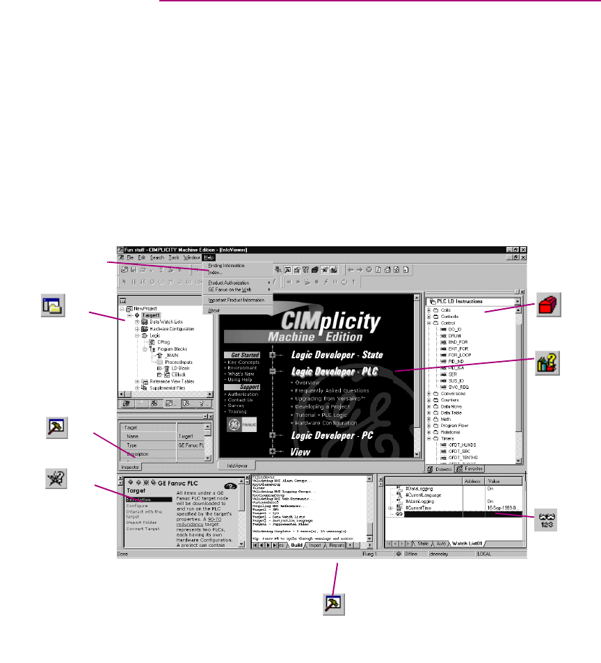
CIMPLICITY Machine Edition
Machine Edition offers you a complete solution for the development of automation
applications in one package. Machine Edition features an integrated development
environment and tools that enable you to spend more time building applications
and less time learning the software. All Machine Edition products are fully
integrated into the environment and interact with each other.
■They share the same set of tools providing a consistent interface throughout the
development process.
■They feature full drag-and-drop capabilities between tools and editors.
■They feature a true scalable solution. You have the choice of what type of
machine your projects run on.
■They automatically display Help in the Companion for what you click on.
The following illustrates a Machine Edition project:
Navigator
Inspector
Companion
Data Watch
Toolchest
InfoViewer
Help Index
Feedback Zone
CIMPLICITY Machine Edition
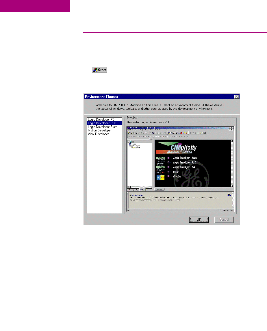
Quick Start
10 CIMPLICITY Logic Developer - PLC Version 4.00 GFK-1918D
2
QUICK START
Machine Edition makes it easy to get started developing a project.
To start Machine Edition
1. Click Start, point to Programs, point to CIMPLICITY Machine Edition and then choose CIMPLICITY
Machine Edition.
After Machine Edition initializes, the Environment Themes dialog box appears.
Note: The Environment Themes dialog box appears automatically the first time you
start Machine Edition. To change the theme later, choose Apply Theme from the
Windows menu.
2. Choose the Logic Developer - PLC theme.
3. Click OK.
When you open a project, the appearance of your Machine Edition screen will
match the preview in the Environment Themes dialog box.
CIMPLICITY Machine Edition
Quick Start
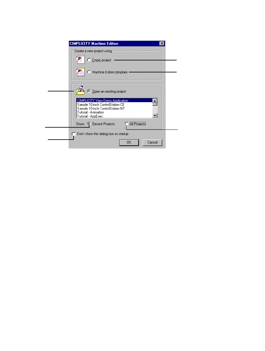
GFK-1918D CIMPLICITY Logic Developer - PLC Version 4.00 11
The CIMPLICITY Machine Edition dialog box appears.
4. Select the appropriate option to open a project. The Open an existing project option is selected by default.
Notes:
■If you select either the Empty project option or the Machine Edition template
option, the New Project dialog box appears and you can continue creating a
new project (see page 12).
■If you select the Open an existing project option, you can also select either the
Recent Projects option or the All Projects option. The Recent Projects option is
selected by default.
5. If you selected the Open an existing project option, select from the list the project that you want to open.
The existing projects include samples and tutorials that you can open and use to
familiarize yourself with Machine Edition.
6. If you want, select the Don’t show this dialog box on startup option.
7. Click OK.
Your project opens in the Machine Edition environment that you specified in the
Environment Themes dialog box.
Select this option if you
want to create a new project
from scratch.
Select this option if you
want to use a Machine Edition
template to create your project.
Select this option if you want
to select an existing project.
Select this option to display only
the projects that have been
used recently. Select this option to display
all existing projects.
Select this check box if you
do not want to see this dialog
box again.
CIMPLICITY Machine Edition
Projects
12 CIMPLICITY Logic Developer - PLC Version 4.00 GFK-1918D
2
PROJECTS
You can create and edit Machine Edition projects using products such as
CIMPLICITY View, Logic Developer - PC, CIMPLICITY Motion, Logic Developer -
State, and Logic Developer - PLC. These products share Machine Edition tools to
provide a high level of integration between the various parts of your project.
You can import folders created with Logicmaster, CimplicityControl, or VersaPro.
Using Logic Developer - PLC, you can build multiple projects to suit your specific
requirements.
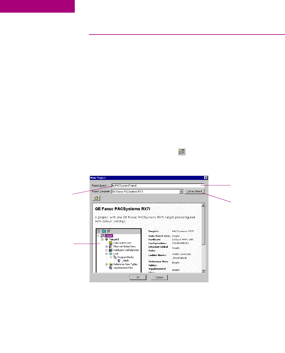
To create a new project using a template
Before creating a project, there are some things you should know:
■The primary components your project will contain.
■The PLC you project will run on.
1. From the File menu, choose New Project, or click on the File toolbar.
The New Project dialog box appears.
2. Choose a Project Template that suits your needs.
3. Enter a descriptive Project Name.
4. Click OK.
Your project opens in the Machine Edition environment.
Enter the name of
your project in the
Project Name box.
Choose your project
template from the
Project Template
list. You can set the selected
project template as the
default template by
clicking the Set as default
button.
A sample description of the
project appears on the
screen.
CIMPLICITY Machine Edition
Projects
GFK-1918D CIMPLICITY Logic Developer - PLC Version 4.00 13
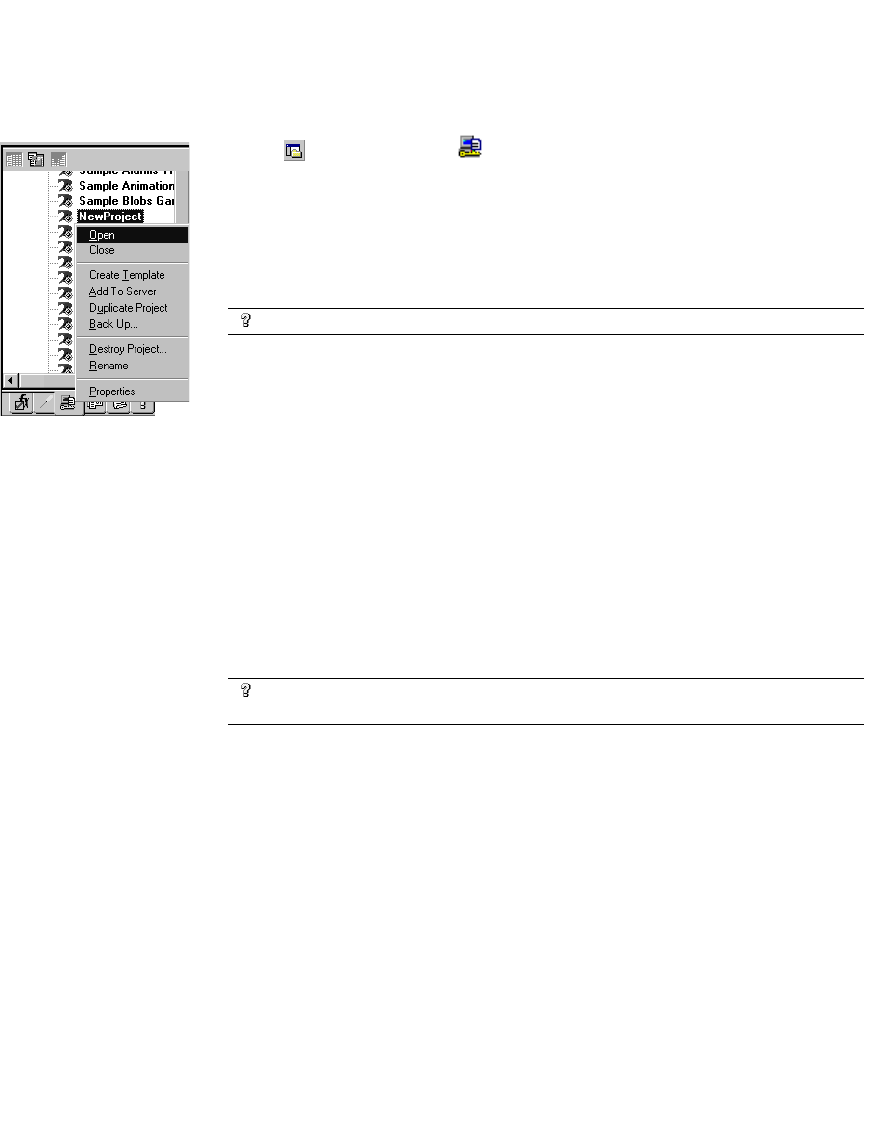
To open an existing project for editing
1. Open the Navigator and choose the Manager tab.
A list of projects is displayed.
2. Right-click a project and choose Open.
Your project loads and is ready for editing.
To import a folder
1. Open the Navigator and choose the Project tab.
2. Select the target that you want to import the folder into.
3. Right-click the target, point to Import, and choose the folder type.
4. In the dialog box that appears, navigate to and double-click the folder you want to import.
Want to know more?
In the Help Index, look up “Projects”.
Want to know more?
In the Help Index, look up “import a CimplicityControl folder”, “import
a Logicmaster folder”, or “import a VersaPro folder”.
Navigator: Manager tab
CIMPLICITY Machine Edition
Tools
14 CIMPLICITY Logic Developer - PLC Version 4.00 GFK-1918D
2
TOOLS
Project development is supported by the Machine Edition tools. Each tool is
opened and closed by means of a button on the Tools toolbar.
A description of each tool’s function is provided below.
The Navigator is a docking tool window containing a set of tabs. Each tab displays
information about your development system in a hierarchical tree structure similar
to Windows Explorer. The available tabs depend on which Machine Edition
products you have installed and what kind of work you are developing or
managing. The Project tab shows the overall organization of your application.
The Feedback Zone window is a docking window used to display several types of
output information generated by Machine Edition components. This interactive
window uses category tabs to organize the output generated from the Machine
Edition products you have installed.
The Inspector lists the properties and current settings for a selected object or
element. You can edit these properties directly in the Inspector. When you select
several objects, the Inspector window lists the properties commom to all of them.
The Inspector window provides a simple method of viewing and setting properties
for all objects.
The Data Watch tool is a runtime debugging tool that enables you to monitor and
edit the values of variables. This tool is useful while working online to a target.
With the Data Watch tool, you can monitor individual variables or user-defined
lists of variables. Data Watch lists can be imported, exported, or saved with a
project.
Navigator
Feedback Zone
Data Watch
Toolchest
Companion
Infoviewer
Inspector
Navigator
Feedback Zone
Inspector
Data Watch

CIMPLICITY Machine Edition
Tools
GFK-1918D CIMPLICITY Logic Developer - PLC Version 4.00 15
The Toolchest is a powerful storehouse of objects you can add to your project. You
can drag most items directly from the Toolchest into Machine Edition editors. You
can choose from predefined objects or create your own reusable fxClasses. The
Toolchest adds true object-oriented capability to Machine Edition.
The Companion provides useful tips and information while you work. While the
Companion is open, it tracks your moves and displays help on whatever item is
currently selected in the Machine Edition environment. It is context-sensitive and
displays a description of whatever you click on the Machine Edition screen.
The InfoViewer is an embedded Web browser used mainly to display
■Machine Edition help.
■Machine Edition reports.
■The documentation associated with a project or target.
If you are familiar with Internet Explorer or Netscape Navigator, then you are
already familiar with the basic InfoViewer interface. Like the Companion, the
InfoViewer is context-sensitive. Press F1 to get help on any item you select in the
Machine Edition environment. A table of contents is found in the InfoView tab of
the Navigator.
Want to know more?
In the Help Index, look up “Tools: an Overview”.
Toolchest
InfoViewer
Companion
CIMPLICITY Machine Edition
Variables
16 CIMPLICITY Logic Developer - PLC Version 4.00 GFK-1918D
2
VARIABLES
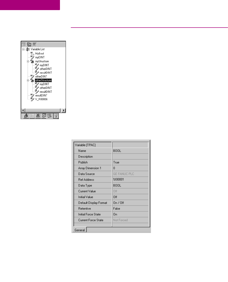
A variable (sometimes called a tag) is a named storage space for data values.
All variables in a project are displayed in the Variables tab of the Navigator. A
variable represents a memory location in the target PLC. Each variable must be
mapped to a reference address (for example, %R00001) for all PLC families except
PACSystems™ RX7i. On a PACSystems™ RX7i, if you don’t map to a specific
reference address, it is considered a symbolic variable. Machine Edition handles
all the mapping for you in a special portion of PACSystems™ user space memory.
The reference address and other properties of a variable, such as data type, are
configured in the Inspector.
Arrays and compound structure variables are supported by Machine Edition.
Variable definitions can be imported from and exported to a variety of file types.
You can edit your variables in a spreadsheet and then import them. Logic
Developer - PLC variables, that is, variables used on GE Fanuc PLC and
PACSystems™ targets, can be viewed in CIMPLICITY View. The following diagram
shows the Inspector displaying a typical set of variable properties.
Navigator: Variables tab
CIMPLICITY Machine Edition
Variables
GFK-1918D CIMPLICITY Logic Developer - PLC Version 4.00 17
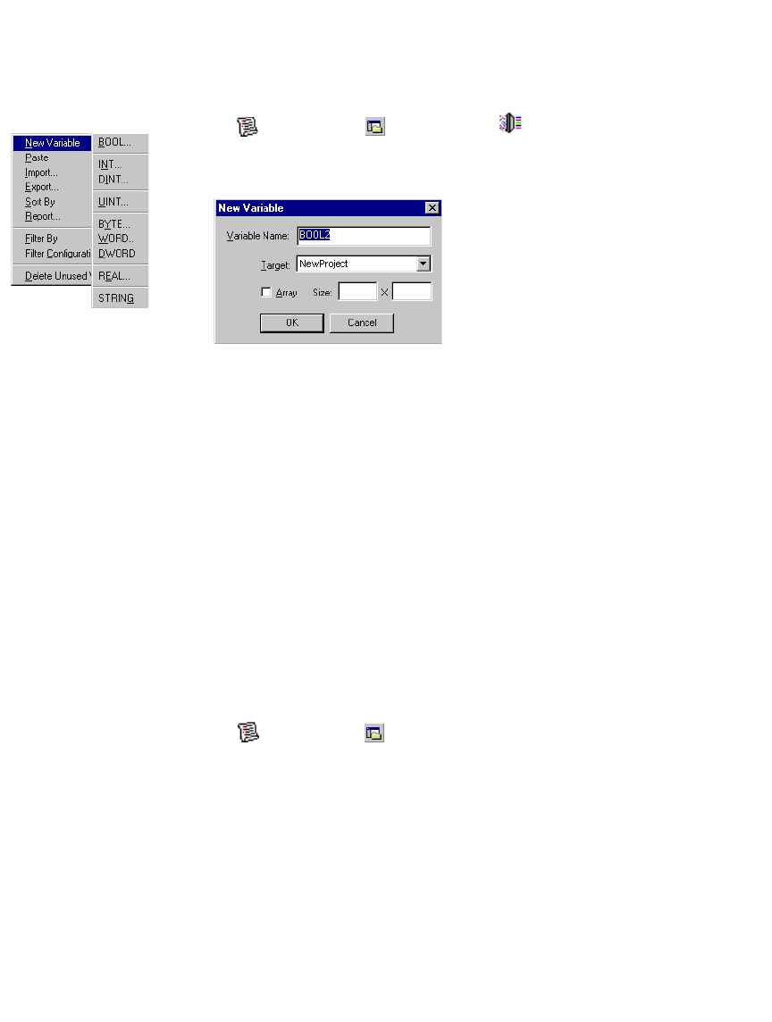
To create a variable
1. In the Variables tab of the Navigator, right-click Variable List, point to New Variable and then
choose the data type of the variable.
The New Variable dialog box appears.
2. Type a name for the variable and press ENTER.
Variable names can range from 1 to 32 characters, begin with a letter, contain
upper or lower case letters, use numbers between zero and nine, and use the
underscore character (“_”).
3. Select the target the variable will be used in.
4. If the new variable is an array, select the Array check box and enter the size(s).
5. Click OK.
A new variable with a default name appears in the list.
To map a variable to PLC memory
In order to successfully download a project to the PLC, variables must be properly
mapped to the PLC’s memory, unless they are symbolic variables, which a
PACSystems™ RX7i will automatically map for you. There are two ways to map a
non-symbolic variable.
First method:
1. In the Variables tab of the Navigator, right-click a variable and choose Properties.
The Inspector displays the properties of the variable.
2. In the Ref Address field, enter an address. You can:
■Spell out the exact address, for example, %R00123 or 123R. In either case this
maps the variable to %R00123.
■Enter only the memory area, for example %R. This maps the variable to the next
highest available address. For example, if %R00122 was the last address used,
entering %R maps the variable to %R00123.
New Variable menu
CIMPLICITY Machine Edition
Variables
18 CIMPLICITY Logic Developer - PLC Version 4.00 GFK-1918D
2
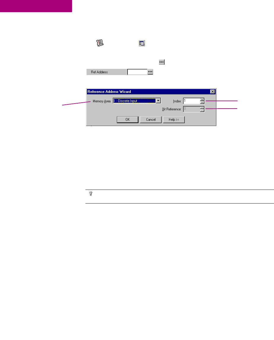
Second method:
1. In the Variables tab of the Navigator, right-click a variable and choose Properties.
The Inspector displays the properties of the variable.
2. Click the Ref Address field and then click the button.
The Reference Address Wizard appears.
3. From the Memory Area list, choose a region of PLC memory.
4. In the Index box, enter an index from the beginning of the region.
5. Select a bit reference.
The Bit Reference box is available only if you're mapping a BOOL variable to 16-
bit memory area on a PACSystems™ PLC.
6. Click OK.
Your variable is mapped to the Reference Address.
Want to know more?
In the Help Index, look up “Variables”, “Importing variables from a file”,
“Symbolic Variable”, and “Bit addressing in 16-bit memory”.
Select a region of Select a bit reference
for a BOOL variable in
16-bit memory.
Select an index
CIMPLICITY Machine Edition
Options
GFK-1918D CIMPLICITY Logic Developer - PLC Version 4.00 19
OPTIONS
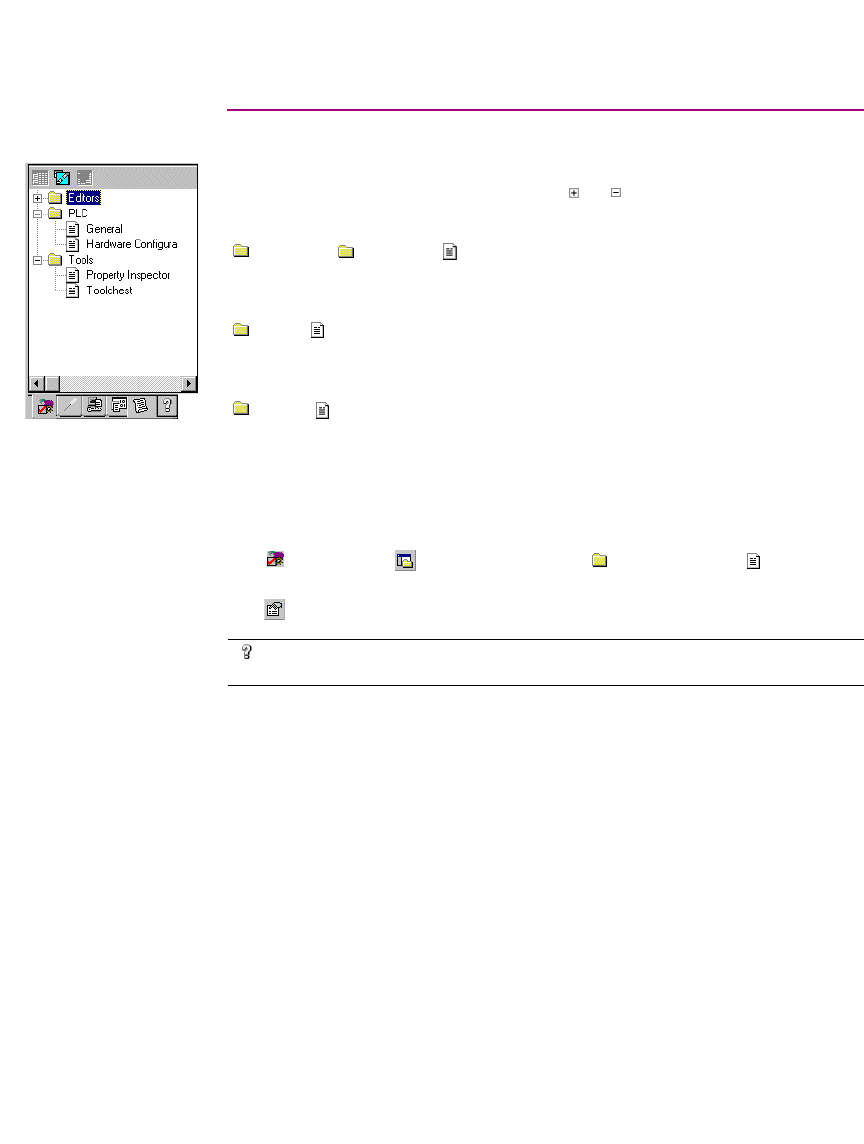
The Options tab of the Navigator contains option and preference settings. Options
are organized into folders and pages. Click or to expand or collapse folders.
Examples:
Editors > Ladder > View >Coil Justification: The leftmost column in
which coils can be placed; also the column where the right power rail resides. The
default is 10.
PLC> General > Duplicate Addresses: Indicates whether to prevent, warn
about, or ignore mapping two variables of the same data size (1, 8, 16, 32, or 64
bits) and length (array size) to the same reference address.
PLC > Hardware Configuration >New Reference Assignment: The way in
which default reference addresses will be assigned when modules are added to the
Hardware Configuration.
To set options and preferences
1. In the Options tab of the Navigator, expand an options folder and right-click a page within the
folder to display the option’s properties in the Inspector.
2. In the Inspector, edit the option’s settings as needed..
Want to know more?
In the Help Index, look up “Options”, “Confirmations”, “PLC Options”,
and “General Options”.
Navigator: Options tab
CIMPLICITY Machine Edition
Machine Edition Help
20 CIMPLICITY Logic Developer - PLC Version 4.00 GFK-1918D
2
MACHINE EDITION HELP
CIMPLICITY Machine Edition includes a comprehensive online help system that
enables you to access specific help topics while working with Machine Edition.
Use the InfoViewer or Companion to access help.
Companion Help
The Companion is a Machine Edition help system that provides useful tips and
information while you work. While the Companion is open, it displays help on
whatever item is currently selected in the Machine Edition environment, tracking
your movements while you work.
To use Companion help
1. Ensure the Companion window is open. To open it, press Shift+F11.
2. Click on any item on the screen.
A description of the item you clicked appears in the Companion.
InfoViewer Help
The InfoViewer, another Machine Edition help system, provides detailed
information. The InfoViewer has its own toolbar for navigating the help system, a
Table of Contents (in the InfoView tab of the Navigator), and a searchable index. As
with the Companion, InfoViewer help is context-sensitive. Click an item on the
screen and press F1 to display the appropriate topic in the InfoViewer.
CIMPLICITY Machine Edition
Machine Edition Help
GFK-1918D CIMPLICITY Logic Developer - PLC Version 4.00 21
To use the Help index
1. From the Help menu, choose Index.
The Index dialog box appears.
2. Enter a keyword in the top text box or select one in the middle text box.
3. Click List Topics.
A list of topics appears in the bottom text box. The topics are sorted by their rating
or likelihood of containing the correct information.
4. In the bottom text box, select a topic to display.
5. Click Display.
The selected Help topic is displayed in the InfoViewer.
CIMPLICITY Machine Edition
Machine Edition Help
22 CIMPLICITY Logic Developer - PLC Version 4.00 GFK-1918D
2
To look up topics in the Help Table of Contents
1. Open the InfoView tab of the Navigator.
A table of contents for the entire help system appears.
2. Expand Libraries and Books to locate a topic of interest
3. Double-click a topic.
The topic is displayed in the InfoViewer.
Navigator: InfoView Tab
CIMPLICITY Logic Developer - PLC Version 4.00 23
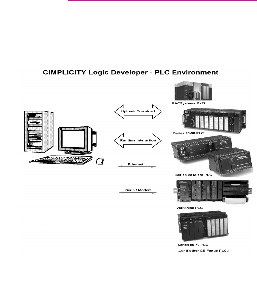
3
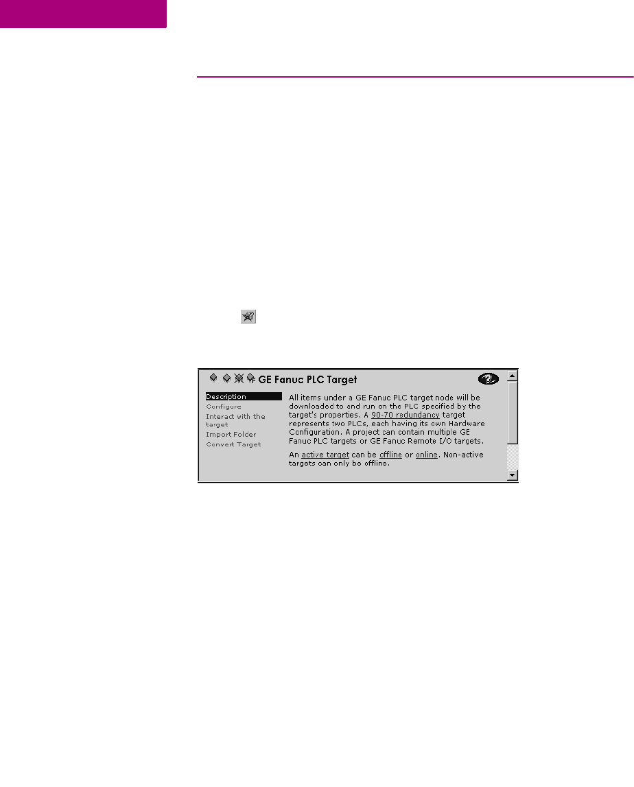
GE Fanuc PLC Targets
A target represents a run-time destination of the programs you develop with
Logic Developer - PLC. Each target contains all of the components that will
download to it. Logic Developer - PLC supports the following GE Fanuc PLC target
families:
■PACSystems™ RX7i
■Series 90™-70 PLC
■Series 90™-30 PLC
■VersaMax® PLC
■VersaMax® Nano/Micro PLC
■Series 90™ Micro PLC
and the following remote I/O interface targets:
■GE Fanuc Series 90™-70 Genius Remote I/O Scanner
■GE Fanuc VersaMax® Ethernet
■GE Fanuc VersaMax® Genius
■GE Fanuc VersaMax® Profibus
Navigator: New PACSystems™ Project
GE Fanuc PLC Targets
Addinging, Configuring and Converting Targets
24 CIMPLICITY Logic Developer - PLC Version 4.00 GFK-1918D
3
ADDINGING, CONFIGURING AND CONVERTING
TARGETS
Adding Targets
Normally a target is present in a project when you use a template to create the
project (see page 12). A project can contain multiple targets. The actual largest
number possible may vary, depending on the available memory on your computer,
the operating system you are using, or the available disk space, etc.
One target is required for each PLC or remote I/O adapter your project accesses,
except when you are using CPU redundancy. In this case, one target contains a
Primary Hardware Configuration and a Secondary Hardware Configuration, which
respectively correspond to the primary PLC and the redundant PLC. For more
information, see page 50.
Existing targets can be converted from one GE Fanuc PLC family to another. For
more information, see page 26.
To add a target to a project
1. In the Project tab of the Navigator, right-click the Project node and point to Add Target.
2. Point to GE Fanuc PLC or GE Fanuc Remote I/O and then respectively choose the PLC family or the Remote
I/O.
Project right-click menu

GE Fanuc PLC Targets
Addinging, Configuring and Converting Targets
GFK-1918D CIMPLICITY Logic Developer - PLC Version 4.00 25
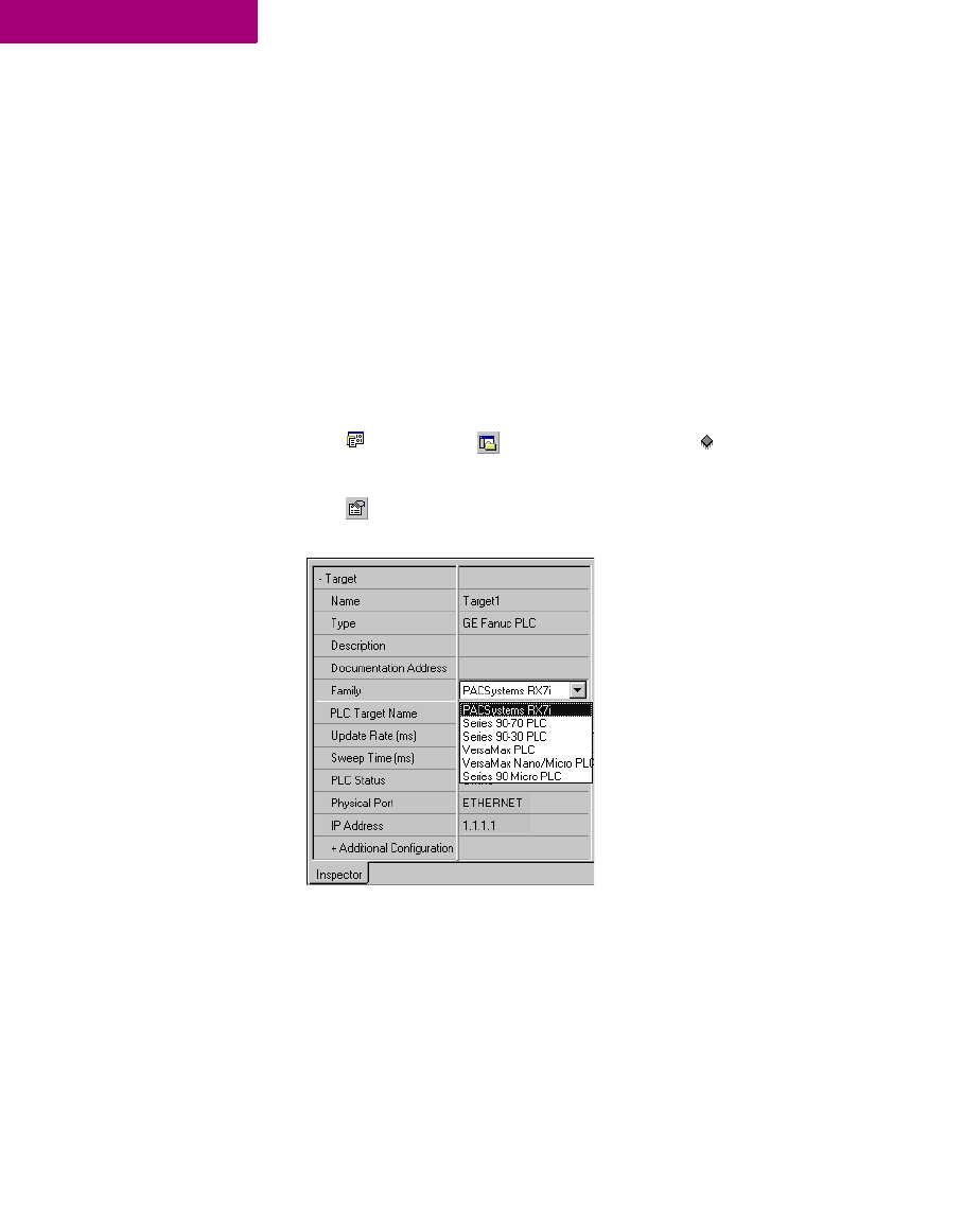
Configuring Targets
The properties of a target specify the PLC family, the communication connections
between your computer and the PLC, and various other settings. All properties are
edited in the Inspector. The following table describes a PLC target’s properties:
To configure a PLC target
1. In the Project tab of the Navigator, right-click a target and choose Properties.
The properties of the target appear in the Inspector.
2. In the Inspector, configure the properties as needed.
Name
Edit the name for your target in this field.
Type
The type of target is set by default to GE Fanuc PLC. Note:
Logic Developer - PLC is operational with GE Fanuc PLCs only.
Description
Enter a description of your project in this field. The maximum
characters is 255.
Documentation Address
Enter the URL where your project documentation is stored.
Family
By changing the PLC type in this field, you initiate a target
conversion.
Caution: Changes are irreversible.
PLC Target Name
The name of the target as stored on the PLC target.
Update Rate (ms)
Set the rate at which the screen is updated while online.
Sweep Time (ms)
The sweep time of the PLC when online is also displayed on
the status bar.
PLC Status
The online/offline, run/stop status of the PLC.
Dual HWC
(Series 90™-70 only.) Indicates whether HWC redundancy is
set up. Change the field to False to delete the secondary HWC.
Selected HWC
(Displayed only if Dual HWC is set to True.) Change the
selected HWC in this field.
Physical Port
Choose the type of connection to the PLC (Ethernet, COM, or
modem).
IP Address
(Ethernet protocol only.) Set the IP address of the PLC.
Additional Configuration
Group of properties used for the detailed configuration of your
communication connection.
GE Fanuc PLC Targets
Addinging, Configuring and Converting Targets
26 CIMPLICITY Logic Developer - PLC Version 4.00 GFK-1918D
3
Converting Targets
With Logic Developer - PLC, you can convert targets from one GE Fanuc PLC
family type to another. This enables you, for example, to take logic written for a
Series 90™-70 PLC and convert it for use on a PACSystems™ RX7i. However,
target conversions are irreversible; when logic blocks are deleted during a
conversion, they cannot be restored. It is recommended that you make a backup of
your project before converting a target in it. There may also be execution
differences when converting an application from one GE Fanuc PLC family type to
another. You must validate the application execution prior to deployment into a
production environment.
To convert a target
1. In the Project tab of the Navigator, right-click an existing target and choose Properties.
The Inspector displays the target’s properties.
2. In the Inspector, click Family.
3. From the list, choose the new PLC Family you want to convert the target to.
Target conversion involves the following changes:
■Stripping all the configured modules from the original Hardware Configuration
(HWC) and setting up the destination family’s default HWC, with a single
power supply and a CPU.
Note: PACSystems™ RX7i supports many Series 90™-70 modules and some
Series 90™-70 expansion racks. When converting a Series 90™-70 target to a
PACSystems™ RX7i target, the supported modules and expansion racks are
retained (with rare exceptions). The modules’ parameters are also retained or

GE Fanuc PLC Targets
Addinging, Configuring and Converting Targets
GFK-1918D CIMPLICITY Logic Developer - PLC Version 4.00 27
converted to the nearest equivalent. Unsupported expansion racks are
converted to the nearest equivalent. which retains the supported modules. All
Hardware Configuration changes made during the conversion are documented
in a target conversion report.
■Deleting or adding target components, blocks, and/or programs.
■Updating the system variables, including the fault locating references.
■Displaying a conversion report in the InfoViewer when converting to
PACSystems™ targets only
Warning: Changing the PLC Family can result in logic in your project becoming
invalid.
Note: PLC hardware must be configured before it will be operational. For detailed
information on hardware configuration, see page 46..
Want to know more?
In the Help Index, look up “Target Conversions (GE Fanuc PLC Targets)”.

GE Fanuc PLC Targets
Configuring Communication
28 CIMPLICITY Logic Developer - PLC Version 4.00 GFK-1918D
3
CONFIGURING COMMUNICATION
In order for Logic Developer - PLC to communicate with a target PLC, a
connection must be properly configured. The properties of a target are adjustable
to accommodate your connection(s).
To configure an Ethernet or serial connection
1. In the Project tab of the Navigator, right-click a target and choose Properties.
The Inspector opens showing the target’s properties.
2. In the Inspector, set the Physical Port property to Ethernet or a COM port (or a modem if one is installed).
3. If the Physical Port is Ethernet, enter the IP Address of the target PLC.
Note: You can connect to a GE Fanuc PACSystems™ RX7i by means of Ethernet
only.
4. Double-click Additional Configuration to access the detailed settings for your connection.
Note: Serial communication with a non-PACSystems™ PLC is always available if it
is the only device connected and an SNP_ID is not specified. An IP address must
be set in the PLC before an Ethernet link can be established.
Configuring Communication for PACSystems™
The only communication method supported by a PACSystems™ is Ethernet. This
ensures fast communication, because every PACSystems™ has an embedded
Ethernet adapter.
To configure communication with a PACSystems™ RX7i
1. Physically connect the PACSystems™ RX7i to the Ethernet network.
2. Set up a temporary IP address. For more information, see “To set a temporary IP address for a PACSystems™ RX7i”.
The temporary IP address enables you to communicate with the PACSystems™
RX7i the first time.
3. Do one of the following:
If there is already a hardware configuration stored on the PACSystems™ RX7i
target, it contains a permanent IP address. To obtain this permanent IP address
from the PACSystems™, upload the hardware configuration from the
PACSystems™ RX7i.
- OR -
Want to know more?
In the Help Index, look up “Configuring a direct connection”.
GE Fanuc PLC Targets
Configuring Communication
GFK-1918D CIMPLICITY Logic Developer - PLC Version 4.00 29
Set up a permanent IP address. For more information, see “To set a permanent IP
address for a PACSystems™ RX7i”.
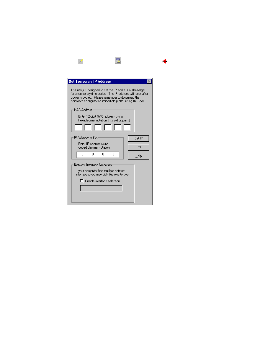
To set a temporary IP address for a PACSystems™ RX7i
1. In the Utilities tab of the Navigator, double-click Set Temporary IP Address.
The Set Temporary IP Address dialog box appears.
2. In the MAC Address field, specify the MAC address for the PACSystems™ RX7i.
3. In the IP Address to Set field, specify the temporary IP address you want to set on the PACSystems™ RX7i.
4. If required, select the Network Interface Selection check box and specify the network interface the PACSystems™
RX7i is located on.
5. Click the Set IP button.
The IP address of the specified PLC or device is temporarily set to the indicated
address.
Warning: The IP address set by the Set Temporary IP Address utility will not be
retained through a power cycle. If you want to set a permanent IP address, you
must do so by other methods.
GE Fanuc PLC Targets
Configuring Communication
30 CIMPLICITY Logic Developer - PLC Version 4.00 GFK-1918D
3
To set a permanent IP address for a PACSystems™ RX7i
1. In the Project tab of the Navigator, right-click the target and choose Properties.
The Inspector displays the target’s properties.
2. In the IP Address property, enter an IP address.
3. Download the hardware configuration to the PACSystems™ RX7i. For more information, see page 35.
Note: Ensure that you have configured the rest of the hardware configuration
before downloading it.
Configuring Communication for non-PACSystems™ PLCs
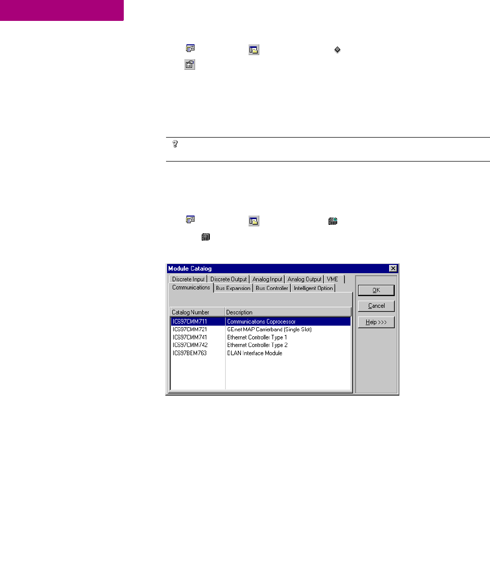
To set an IP address for Series 90™-70 PLCs
1. In the Project tab of the Navigator, expand the Hardware Configuration node.
2. Expand the Main Rack and double-click the slot where you want to add a communications module.
The Module Catalog appears.
3. Choose the Communications tab and select the communications module you want to add.
Select either IC697CMM741 or IC697CMM742.
4. Click OK.
The Parameter editor opens showing the configuration settings for the module.
5. In the Settings tab, double-click the IP Address parameter.
Want to know more?
In the Help Index, look up “Configuring communication with a
PACSystems™ RX7i” and “Set Temporary IP Address utility”.
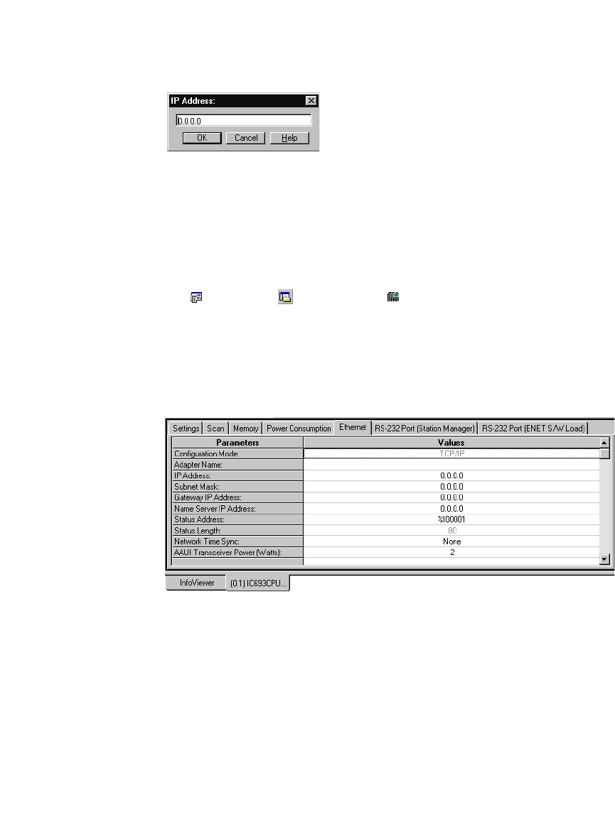
GE Fanuc PLC Targets
Configuring Communication
GFK-1918D CIMPLICITY Logic Developer - PLC Version 4.00 31
The IP Address dialog box appears..
6. Enter the IP Address and click OK.
To set an IP address for a Series 90™-30 CPU364 or CPU374
Note: For CPU364 and higher-end Series 90™-30 CPUs, the Ethernet adapter is
built into the CPU. For other Series 90™-30 CPUs, the Ethernet connects through
an optional expansion slot on the rack.
1. Obtain an IP address, perhaps from your network administrator.
2. In the Project tab of the Navigator, expand the Hardware Configuration node to reveal the rack and
slot containing a CPU364 or CPU374.
3. Right-click the slot containing the CPU364 or CPU374 and choose Configure.
The Parameter editor appears.
4. In the Parameter editor, click the Ethernet tab.
The Parameter editor displays the contents of the Ethernet tab.
5. Double- click the IP address parameter.
The IP Address dialog box appears
6. Enter the IP address in the box and click OK.

GE Fanuc PLC Targets
Configuring Communication
32 CIMPLICITY Logic Developer - PLC Version 4.00 GFK-1918D
3
To set an IP address for other Series 90™-30 CPUs (not CPU364 or CPU374)
1. In the Project tab of the Navigator, expand the Hardware Configuration node.
2. Right-click the slot containing an Ethernet Interface Module (IC693CMM321)and choose Configure.
The Parameter editor opens showing the configuration settings for the module.
3. In the Settings tab, double-click the IP Address field.
The IP Address dialog box appears.
4. Enter the IP address and click OK.
To download an IP address to a non-PACSystems™ target
1. Configure a CPU or Ethernet COM Module with an IP address using Hardware Configuration.
2. Right-click the target and choose Properties.
The Inspector displays the target’s properties.
3. In the Physical Port property, select a serial connection.
4. Right-click the target and choose Go Online.
5. Right-click the target and choose Download to PLC.
The Download to PLC dialog box appears.
6. Select Hardware Configuration and click OK.
The IP address is assigned to the PLC.
7. Right-click the target anch choose Go Offline.
8. Right-click the target and choose Properties.
9. In the Physical Port property, select Ethernet.
The next time you go online, Machine Edition will use an Ethernet connection with
the specified IP address.

GE Fanuc PLC Targets
Interacting with the PLC
GFK-1918D CIMPLICITY Logic Developer - PLC Version 4.00 33
INTERACTING WITH THE PLC
Communicating with the PLC is necessary to perform such operations as storing
and loading programs or monitoring data values and PLC status information. You
can connect to a PLC from Logic Developer - PLC over a serial, Ethernet or modem
connection, depending on the capabilities of the PLC.
All interactions with a target are available from the target’s right-click menu.
Validating a Target
Validating your project detects any syntax errors that may be present. Error
messages are generated for each error and displayed in the Feedback Zone. A
project containing errors cannot be downloaded. For that reason, whenever you
initiate a download, the logic is automatically validated.
To validate a target
• In the Project tab of the Navigator, right-click a target and choose Validate.
Logic Developer - PLC checks all items under the target for syntax errors. Any
errors detected are noted with messages in the Build tab of the Feedback Zone.
Tip: Double-click an error message to locate the noted error in your project. The
appropriate editor or tool opens automatically with the item in question selected.
Tips showing you how to proceed are displayed in the Companion. To open the
Companion, press SHIFT + F11.
Online/Offline
When offline from a target PLC, there is no ongoing communication between the
PLC and your development computer. When offline from the target PLC the
number and type of interactions available are limited, and the actual
communication link is not required as long as you only edit logic. If a
communication link has been configured and the Offline PLC Operations option is
enabled, you can:
■Download to the PLC .
■Upload from the PLC.
■Start the PLC.
■Stop the PLC.
■Clear the PLC.
GE Fanuc PLC Targets
Interacting with the PLC
34 CIMPLICITY Logic Developer - PLC Version 4.00 GFK-1918D
3
When you issue such commands, the communication link becomes active while
performing the operation and then returns to an idle state. When the Offline PLC
Operations option is disabled, the only PLC operation you can perform while
offline is to go online.
Note: You enable or disable the PLC Offline Operations option in the Options tab
of the Navigator. For more information, see page 19.
While online to a target PLC, a communication link exists and is active and you
have an ongoing real-time communication with the PLC. You can perform
commands to monitor and control the PLC’s action and memory including the
commands available when offline. Also, while online, the LD editor displays a
graphical representation of LD logic as it executes, if the PLC’s project is equal to
the current project. You can edit LD logic while online; you are prompted to
download your word-for-word changes. For more information on word-for-word
changes, see page 73.
To go online to a PLC
• In the Project tab of the Navigator, right-click a target PLC and choose Go Online.
Logic Developer - PLC connects your project to the PLC. The online status is
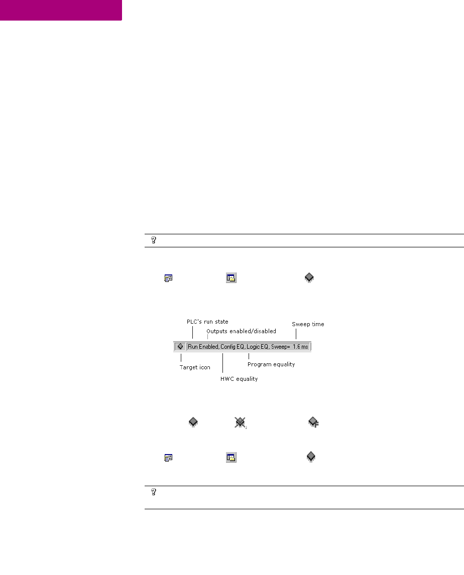
indicated by the target icon in the Project tab and on the status bar.
Note: When online to a PLC, the target icon in the Project tab of the Navigator
appears as (equal), (not equal), or (stop faulted).
To go offline from a PLC
• In the Project tab of the Navigator, right-click a target PLC and choose Go Offline.
Logic Developer - PLC goes offline.
Want to know more?
In the Help Index, look up “Offline versus Online”.
Want to know more?
In the Help Index, look up “going online with a PLC” and “going offline
from a PLC”.
GE Fanuc PLC Targets
Interacting with the PLC
GFK-1918D CIMPLICITY Logic Developer - PLC Version 4.00 35
Upload/Download
The download process creates (or builds) and validates all runtime files necessary
for a target to perform its role in a completed project. The compiled project is then
transferred to the target hardware via the communication connection previously
configured. For more information, see page 28.
The upload process acquires a project from an active PLC target and transfers it to
Logic Developer - PLC for editing.
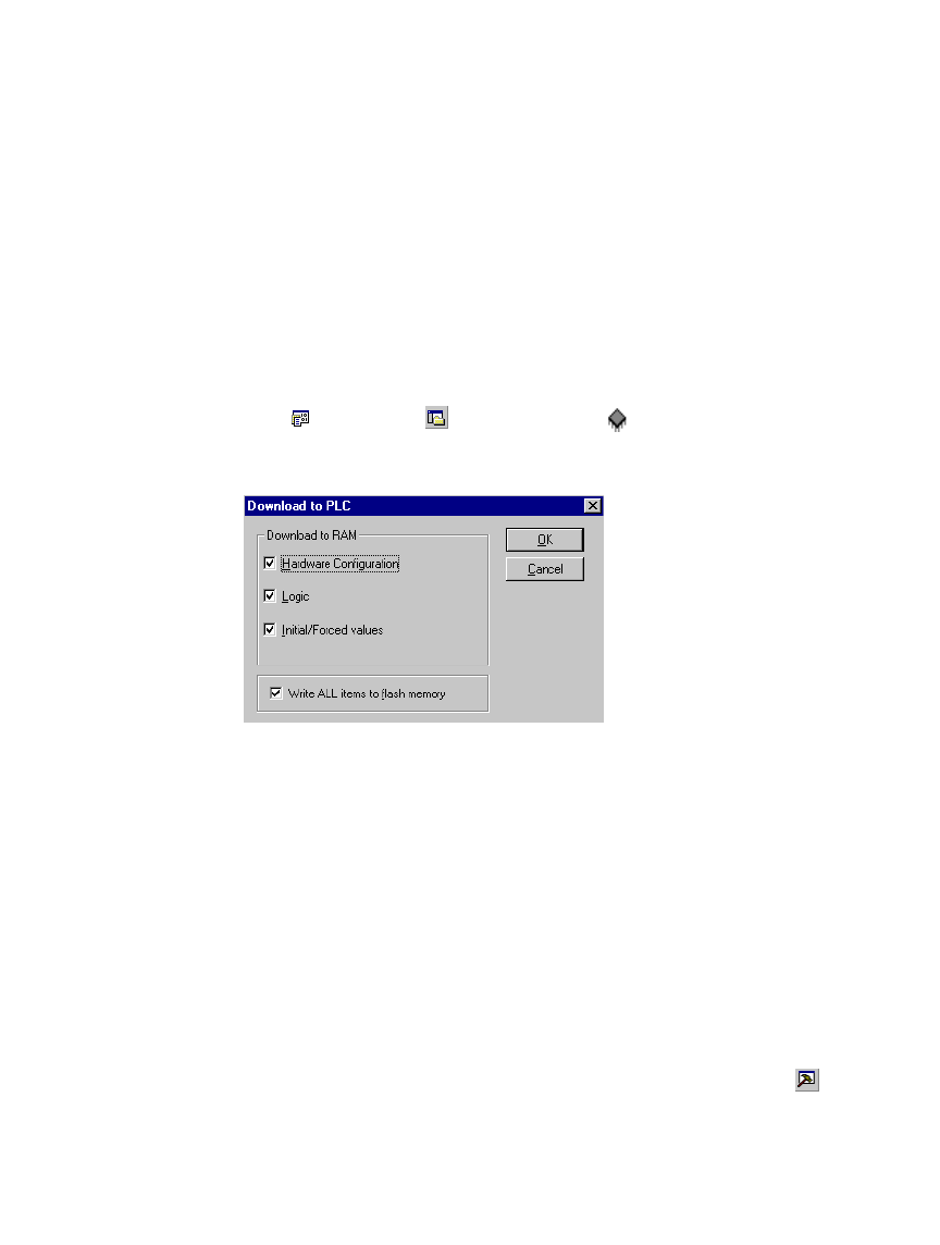
To download to a target PLC
1. In the Project tab of the Navigator, right-click the target to which you want to download files and
choose Download to PLC.
The Download to PLC dialog box appears.
Note: If the PLC is running, you can download only logic that is not equal to the
PLC’s current logic and the Download to PLC dialog box does not appear.
2. Choose the items you want to download and click OK.
Tip: To download files for all targets in a project, right-click the project node and
choose Download All. If you want to download files to the active target, choose
Download Active Target.
Note: Only one project can be downloaded to a target at a time. If you download
to a target machine that already has a project on it, the existing project is
overwritten.
For each target that you download to, Machine Edition saves the project, performs
a validation, builds the runtime files and attempts to establish a connection to the
target. Any errors that occur are displayed in the Build tab of the Feedback
GE Fanuc PLC Targets
Interacting with the PLC
36 CIMPLICITY Logic Developer - PLC Version 4.00 GFK-1918D
3
Zone. If connection to a target is successful, Machine Edition sends all the
necessary runtime files to the PLC.
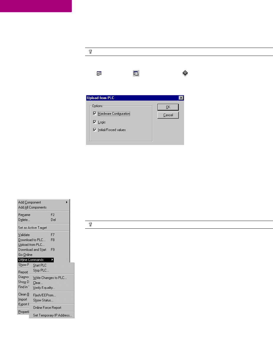
To upload files from a PLC
1. In the Project tab of the Navigator, right-click the target PLC from which you want to upload
information and choose Upload from PLC.
The Upload from PLC dialog box appears.
Note: If you are uploading from Logic Developer - State, only the Hardware
Configuration can be uploaded.
2. Choose the item(s) you want to upload and click OK.
Logic Developer - PLC connects to the PLC and uploads the selected item(s) to
Logic Developer - PLC. If you already had a version of the PLC’s project open, the
uploaded project merges with the existing project. This ensures that all variable
names are retained throughout the uploading process. If you upload to an empty
target, all variables are assigned default names. For example, %R00001 is named
R00001.
Run/Stop
You can set a target PLC to Run or Stop mode. In Stop mode, you can choose to
enable or disable the outputs.
If you are starting a PACSystems™ RX7i or Series 90™-70 PLC, you can choose to
have outputs enabled or disabled.
Want to know more?
In the Help Index, look up “downloading to PLC”.
Want to know more?
In the Help Index, look up “uploading from PLC”.
GE Fanuc PLC Targets
Interacting with the PLC
GFK-1918D CIMPLICITY Logic Developer - PLC Version 4.00 37
To start a PLC
• In the Project tab of the Navigator, right-click a target, point to Online Commands or to Offline
Commands, and then choose Start PLC.
The target PLC begins executing its program.
To stop a PLC
1. In the Project tab of the Navigator, right-click a target, point to Online Commands or to Offline
Commands, and choose Stop PLC.
The Stop PLC dialog box appears, prompting you to enable or disable the PLC’s
outputs.
2. Select an option.
3. Click OK.
The target PLC stops executing its program.
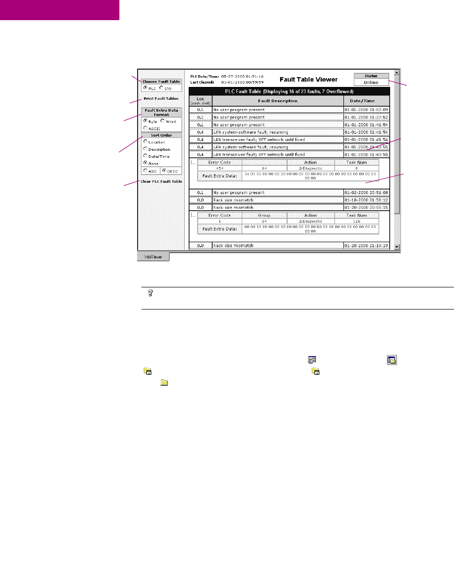
Fault Tables
The PLC and I/O Fault Tables display fault information logged by the CPU or
modules in the PLC. This information is used to determine if there are problems
with the PLC hardware or software running in the PLC’s CPU. To view the PLC and
I/O fault tables, your computer must be online to the PLC.
To view the fault table reports
• In the Project tab of the Navigator, right-click the target you want to report on and choose
Diagnostics.
Want to know more?
In the Help Index, look up “starting the PLC” and “stopping the PLC”.
GE Fanuc PLC Targets
Interacting with the PLC
38 CIMPLICITY Logic Developer - PLC Version 4.00 GFK-1918D
3
The fault table appears in the InfoViewer window.
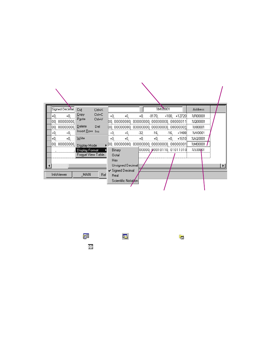
Reference View Tables
The Reference View Tables (RVTs) are tables of reference addresses that can be
monitored and changed in real-time. In the Project tab of the Navigator the
Reference View Tables folder contains a Default Tables folder and you can
add user-defined tables to the Reference View Tables folder. A target can have
zero or more user-defined RVTs.
The number of entries contained in an RVT does not affect performance.
Performance is affected only by the number of entries that are displayed and have
to be updated in the view.
An RVT displays data when the parent GE Fanuc PLC target is active and online.
You can configure the appearance of your RVTs in the Options tab of the
Navigator.
Want to know more?
In the Help Index, look up “fault”, then select “Working with the Fault
Tables”.
Print fault table by
clicking here.
Indicates online
status of PLC.
View the date and
time of the faults.
Select the format of
fault data.
Choose the type of
fault information you
require.
Sort fault
information.
Clear fault
information by
clicking here.
Double-click a row to
view details of faults.
GE Fanuc PLC Targets
Interacting with the PLC
GFK-1918D CIMPLICITY Logic Developer - PLC Version 4.00 39
Data values at sequential addresses are displayed, by default, from right to left,
starting at the reference address specified. Both default and user-defined RVTs
display rows of 8 cells for discrete memory and rows of 10 cells for register
memory. The amount of data displayed in the columns depends on the data
display format.
To create a user-defined Reference View Table
• In the Project tab of the Navigator, right-click on the Reference View Tables folder and choose New.
A new Reference View Table with a default name is added to the folder.
Starting AddressSelected address
Format of selected address
Display format can be
selected for individual
cells or the entire
table.
This is the data at the
starting address.
Subsequent addresses
are displayed right to
left by default.

GE Fanuc PLC Targets
Interacting with the PLC
40 CIMPLICITY Logic Developer - PLC Version 4.00 GFK-1918D
3
To work with a Reference View Table
1. n the Project tab of the Navigator, expand the Reference View Tables folder and double-click the
table you want to view.
The Reference View Table appears in the Machine Edition main window.
2. Add reference addresses to the table as required.
Note: You cannot add reference addresses to a default RVT.
3. Format the table entries as desired.
Reports
Reports provide summaries and tables of information about your project. Most
reports are displayed in the InfoViewer window (see page 20). The Reports tab of
the Feedback Zone contains a list of all reports generated since the last
Machine Edition project was opened. The following list shows the types of reports
and logic printouts available in Logic Developer - PLC:
Notes
■An asterisk (*) indicates a logic printout.
■Reports are not generated for LD blocks. Rather, these blocks are printed
directly from the Program Blocks node.
To generate reports
• In the Project tab of the Navigator, right-click a node and choose Report to generate a report on that
node.
A report is automatically generated and displayed in the InfoViewer.
Want to know more?
In the Help Index, look up “RVT”, then select “Working with Reference
View Tables.
Address Use report C block report* Online Force Report
Hardware Configuration report IL block report*
Variables report(s) Local Logic block report *
CAM profile report Motion block report*
Navigator: Project Tab
Reference View Table node
GE Fanuc PLC Targets
Interacting with the PLC
GFK-1918D CIMPLICITY Logic Developer - PLC Version 4.00 41
Note: To generate an Online Force report for a target, you must be online to the
target. Right-click the target, point to Online Commands, and then choose Online
Force Report.
To redisplay a previously generated report
1. In the Feedback Zone, double-click the Reports tab.
A list of previously generated reports appears in the Feedback Zone.
2. From the list choose the report you want to view.
The report displays in the Infoviewer.
Many items in a report contain hyperlinks. Click a hyperlinked item to jump to that
item in the project. For example, if a variable's name appears hyperlinked in a
report, clicking it selects that variable in the Variables tab of the Navigator.
Large reports are often separated into several pages. To view a different page of the
report, scroll to the bottom of the report in the InfoViewer and click the number of
the page you want to view.
To print a report displayed in the InfoViewer
1. Do one of the following:
■Generate the report you want to print.
- OR -
■Redisplay a previously generated report.
2. When the report is displayed, right-click the InfoViewer window and select Print.
To print LD Blocks
1. In the Project tab of the Navigator, expand the Logic node.
2. Right-click the Program Blocks node and choose Print LD Blocks.
The Print dialog box appears.
3. Select the blocks to print.
■To print all of the target's LD blocks, select the All option.
■To print only some of the target's LD blocks, select the Selection option, then
select the check box in front of each block you want to print.
4. Select options as required and click OK.
Want to know more?
In the Help Index, look up “Reports”.
Want to know more?
In the Help Index, look up “printing LD logic”.

CIMPLICITY Logic Developer - PLC Version 4.00 43
4
Hardware Configuration (HWC)
Logic Developer - PLC supports six GE Fanuc PLC families and various remote I/O
interfaces (see page 59) with a variety of CPUs, racks and modules for each. In
order to operate, PLC hardware must be configured with Logic Developer - PLC or
some other GE Fanuc tool. The HWC component of Logic Developer - PLC
provides a way to completely configure your target equipment. This chapter details
specifics on configuring PLC hardware for your operational needs.
The first step in configuring PLC hardware is to select the PLC you want to
configure (see page 24). When creating a new project, you can use a project
template containing default hardware configuration, or you can create an empty
project and configure it manually.
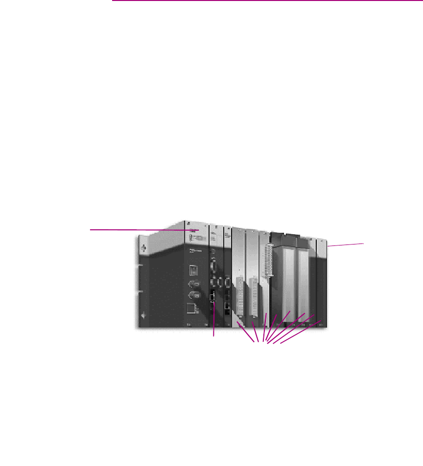
PACSystems™ RX7i
The PACSystems™ RX7i, pictured below, is the newest family of GE Fanuc PLCs.
Most of its features are based on the features of the Series 90™-70 PLC family. The
PACSystems™ RX7i’s Ethernet capabilities are based on the Series 90™-30
CPU364.
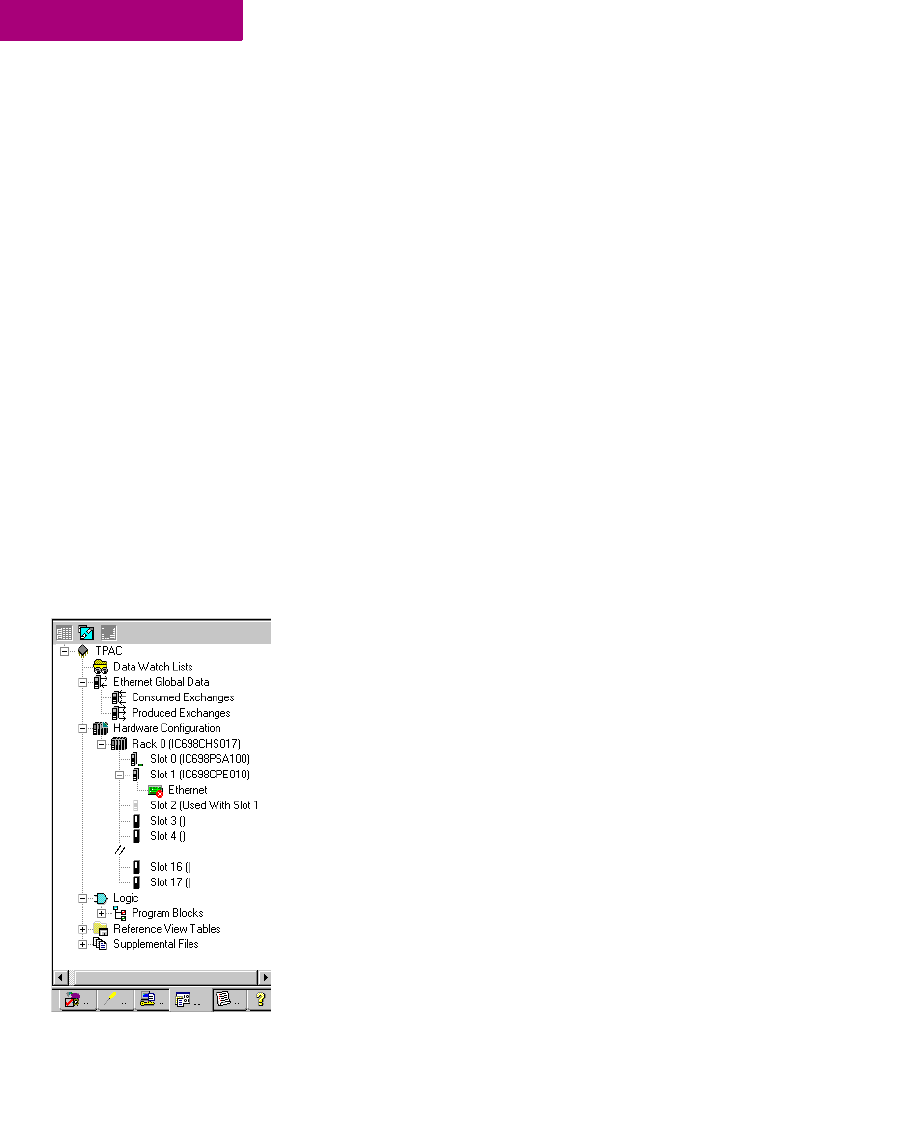
The PACSystems™ RX7i consists of a main rack and up to seven expansion racks.
The PACSystems™ RX7i supports two types of main racks, IC698CHS017 and
IC698CHS117. It supports five types of expansion racks, all of them Series 90™-70
racks. All main racks and expansion racks support three non-intelligent Series
90™-70 fan kits.
Rack
CPU
Power Supply
I/O Modules
Hardware Configuration (HWC)
44 CIMPLICITY Logic Developer - PLC Version 4.00 GFK-1918D
4
The PACSystems™ RX7i main racks have 18 single-width VME slots. Slot 0
supports two power supply modules: IC698PSA100 and IC698PSA350. Slots 1 and
2 are used to house a double-width CPU. PACSystems™ RX7i supports two CPUs
IC698CPE010 (300 mHz) and IC698CPE020 (700 mHz). The PACSystems™ RX7i
communicates through Ethernet only and the CPU has an embedded Ethernet
adapter. In addition to the Ethernet adapter, up to three IC698ETM001 Ethernet
modules can be installed in a PACSystems™ RX7i main rack. The Ethernet
modules occupy only one slot. All of the IC698 modules are supported only on the
main racks.
PACSystems™ RX7i supports several Series 90™-70 modules. Each one is double-
width, that is, it occupies two slots on the main rack, but it occupies only one slot
on a Series 90™-70 expansion rack. You can plug double-width modules into any
two adjacent slots of the main rack except slots 0, 1, or 2. Because slot 17 is a
double-width slot, any module in slot 17 occupies only slot 17. Slot 17 can also
accept a single-width module.
PACSystems™ RX7i supports the following Series 90™-70 bus expansion
modules:
■IC697BEM711
■IC697BEM713
In addition to the Series 90™-70 support, PACSystems™ also supports numerous
Genius devices.
Configuring PACSystems™ RX7i Hardware
When you create a target with a PACSystems™ RX7i rack system, the default HWC
consists of the main rack, with a power supply in slot 0 and a single CPU in slots 1
and 2. You can change the default power supply and CPU, and add single-width
or double-width modules. You can add up to seven secondary racks, and on each
of these, you can add Series 90™-70 modules.
Note: On PACSystems™ RX7i targets, only one rack is added by default. On Series
90™-70 and Series 90™-30 PLCs, seven secondary racks are added by default to
the HWC. You do not need to add them.
The configuration of the PACSystems™ RX7i is detailed in the following
procedures. Configuration procedures for the other PLC types supported by Logic
Developer - PLC are almost identical.
Navigator: Project Tab displaying the
HWC node of a PACSystems™ RX7i
Hardware Configuration (HWC)
GFK-1918D CIMPLICITY Logic Developer - PLC Version 4.00 45
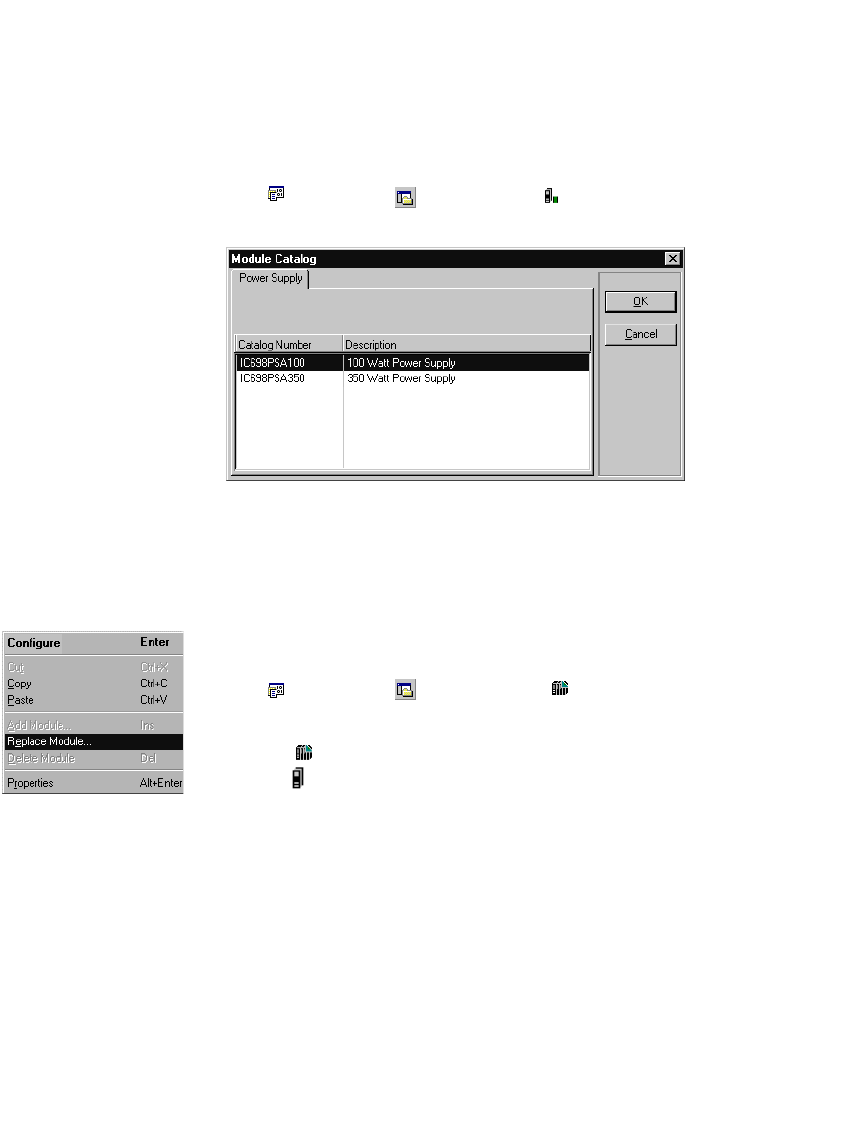
To choose a power supply
The default power supply for the PACSystems™ RX7i is the PSA100. To change the
power supply:
1. In the Project tab of the Navigator, right-click Slot 0 and choose Replace Module.
A list of available power supplies appears.
Note: For other GE Fanuc PLC families, there is no Slot 0. Right-click the PWR
node instead.
2. Select the power supply you have installed in your rack and click OK.
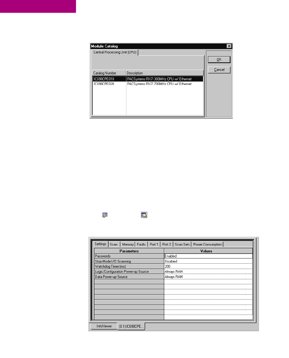
To choose a CPU
The default CPU specified in all project templates for a PACSystems™ RX7i is the
CPE010. To change the CPU:
1. In the Project tab of the Navigator, expand the Hardware Configuration folder.
All racks are revealed.
2. Expand the Main rack.
3. Right-click Slot 1 and choose Replace Module.
HWC right-click menu
Hardware Configuration (HWC)
46 CIMPLICITY Logic Developer - PLC Version 4.00 GFK-1918D
4
The Module Catalog dialog box appears.
4. From the list, select a CPU.
5. Click OK.
A dialog box appears asking if you want to retain the settings from the existing
CPU.
6. Click Yes or No.
Note: On targets other than PACSystems™, you are prompted to confirm the
replacement.
The target is configured with the selected CPU.
To configure a CPU
1. In the Project tab of the Navigator, right-click a slot containing a CPU and choose Configure.
The Parameter editor appears showing all configurable settings for the CPU.
Hardware Configuration (HWC)
GFK-1918D CIMPLICITY Logic Developer - PLC Version 4.00 47
2. Modify the settings as required. For information on any parameter, select the parameter.
Help is displayed in the Companion.
Tip: To open the Companion, press SHIFT+F11.
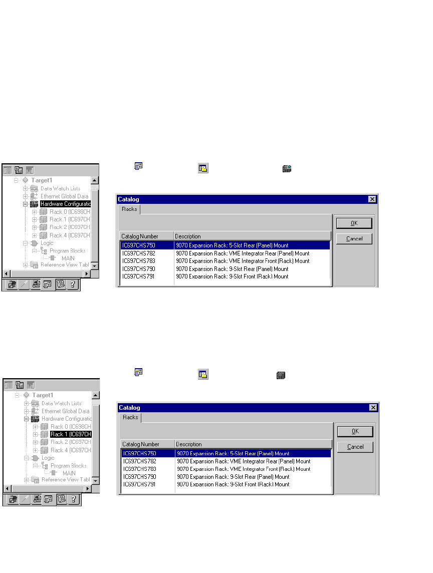
To add a secondary rack (PACSystems™ RX7i only)
Note: On Series 90™-70 and Series 90™-30 PLCs, seven secondary racks are
added by default to the HWC. You do not need to add them.
1. In the Project tab of the Navigator, right-click the HWC node and choose Add Rack.
The Module Catalog dialog box appears listing available rack types.
2. Select a rack and click OK.
The Series 90™-70 expansion rack is added to the PACSystems™ RX7i rack
system. It is assigned an available number in the range of 1 through 7, excluding
numbers already assigned to other expansion racks.
To replace a rack
1. In the Project tab of the Navigator, right-click a rack node and choose Replace Rack.
The Module Catalog dialog box appears listing available rack types.
2. Select a rack and click OK.
Navigator: Project tab
PACSystems™ HWC configuration
Navigator: Project tab
HWC configuration
Hardware Configuration (HWC)
48 CIMPLICITY Logic Developer - PLC Version 4.00 GFK-1918D
4
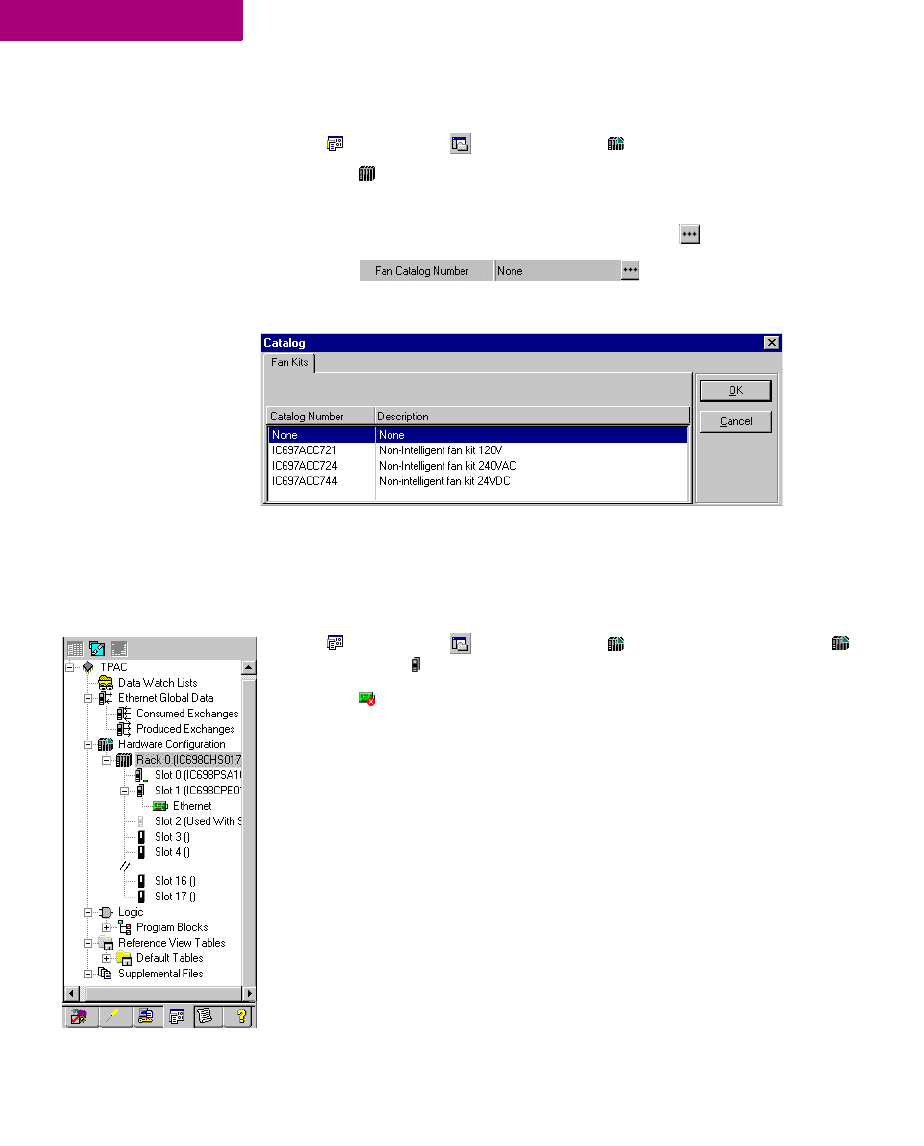
To add a fan kit to a rack (PACSystems™ RX7i only)
1. In the Project tab of the Navigator, expand the Hardware Configuration folder.
2. Right-click a rack and choose Properties.
The rack’s properties are displayed in the Inspector.
3. In the Inspector, to the right of the Fan Catalog Number property, click .
The Fan Kits catalog opens.
4. Select the fan kit you want to add and click OK.
The fan kit is added to the rack.
To configure the Ethernet daughterboard (PACSystems™ RX7i only)
1. In the Project tab of the Navigator, expand the Hardware Configuration folder, then Rack 0 (the
Main rack), and then Slot 1.
2. Double-click Ethernet adapter.
The Parameter Editor window opens.
3. Configure the Ethernet adapter’s parameters as needed.
Navigator: Project tab PACSystems™
Ethernet Daughterboard
Hardware Configuration (HWC)
GFK-1918D CIMPLICITY Logic Developer - PLC Version 4.00 49
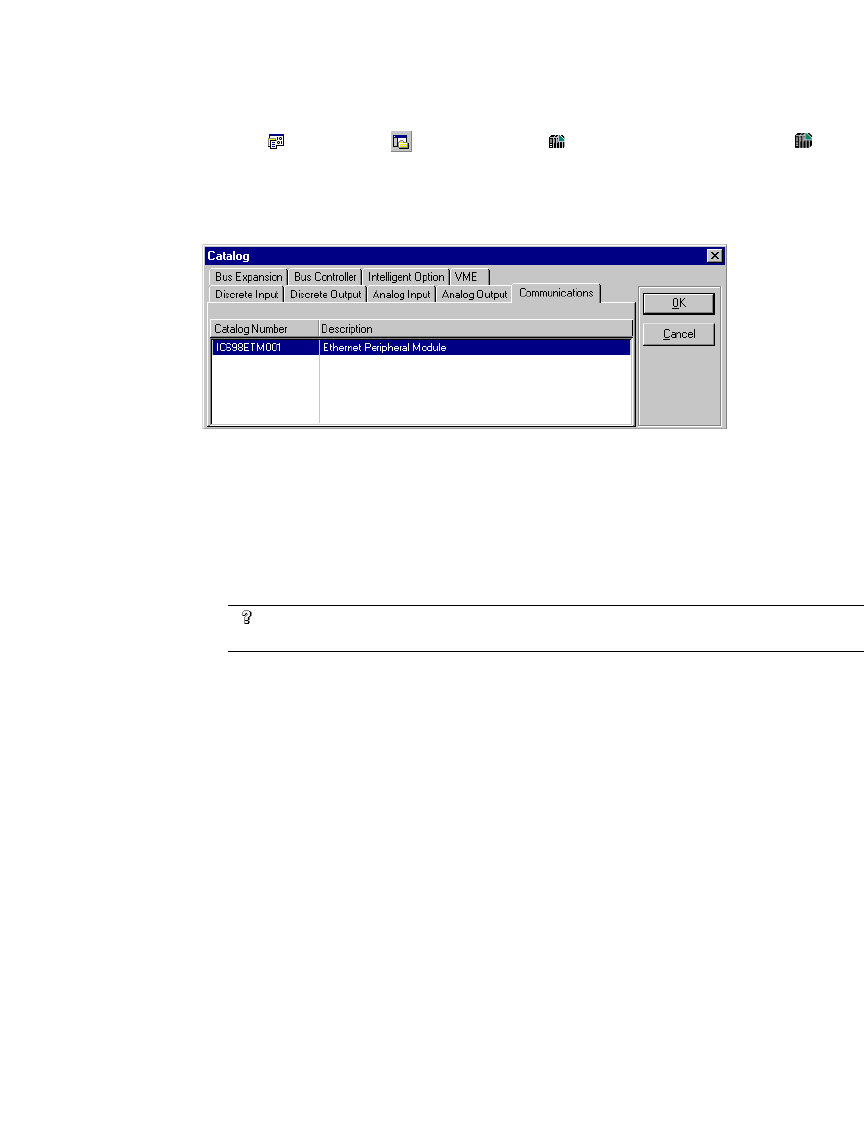
To add an Ethernet module (PACSystems™ RX7i only)
1. In the Project tab of the Navigator, expand the Hardware Configuration folder and then Rack 0
(the Main rack).
2. Right-click the slot you want to add an Ethernet module to and choose Add Module.
The Module Catalog opens.
3. In the Communications tab of the Module Catalog, select the Ethernet Module and click OK.
The Ethernet module is added to the slot.
4. Double-click the Ethernet module (IC698ETM001).
The Parameter Editor opens.
5. Configure the Ethernet module’s parameters as needed.
Want to know more? In the Help Index, look up “configuring a PACSystems™ RX7i Rack
System”.
Hardware Configuration (HWC)
50 CIMPLICITY Logic Developer - PLC Version 4.00 GFK-1918D
4
Redundancy (Series 90™-70 and PACSystems™ RX7i
only)
In redundant systems, two units are set up and configured to share the
responsibility of a single unit. If one unit fails or is taken offline, the other unit
assumes responsibility without interrupting operation of the entire system.
There are three types of redundant systems:
■Basic CPU Redundancy (Series 90™-70 only)
■Genius Redundancy
■CPU Redundancy Over Genius (Series 90™-70 only)
Basic CPU Redundancy
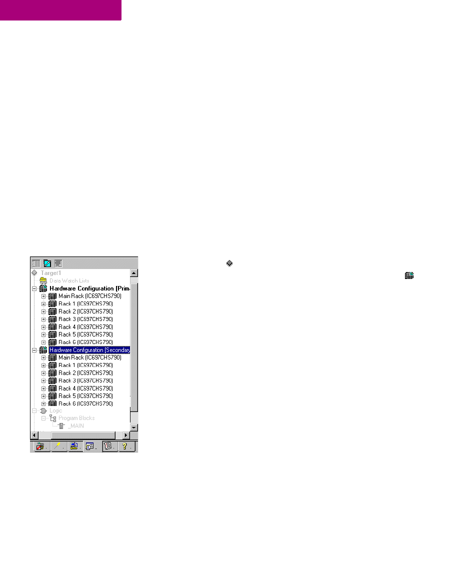
(Series 90™-70 CPUs CGR772 and CGR935 only.) To implement CPU
redundancy, a single target is associated with two physical PLCs, a Primary and
a Secondary. Both PLCs share the same logic, but each has its own Hardware
Configuration (HWC): Primary or Secondary. The selected HWC is the HWC that
you can go online with, download to, upload from, and so on.
Series 90™-70 rack systems support three types of basic CPU redundancy. These
redundant systems can be used in combination with Genius redundancy schemes.
■Single Bus with Preferred Master - uses a single Genius bus with one or more
bus controllers in each PLC. The primary unit is always chosen as the active
unit when the units initially synchronize.
■Single Bus with Floating Master - uses a single Genius bus with one or more bus
controllers in each PLC. No switchover occurs on initial synchronization to
make the primary unit the active unit.
■Dual Bus with Floating Master - uses dual busses with one or more bus
controllers in each PLC. No switchover occurs on initial synchronization. Bus
Switching Modules (BSMs) are required in accordance with configuration of a
dual bus network. This option provides redundancy of both the PLC and the I/O
bus.
Navigation: Project Tab
HWC Node
CPU Redundancy
(Series 90™-70 only)

Hardware Configuration (HWC)
GFK-1918D CIMPLICITY Logic Developer - PLC Version 4.00 51
Genius Redundancy
(PACSystems™ RX7i and Series 90™-70.) A redundant Genius system contains
duplicate components that are controlled in a way that keeps the Genius system
operating properly even if one of the duplicate components fails or is taken out of
service. Redundant Genius systems can be used in combination with Series 90™-
70 redundant CPU systems.
You can configure five types of redundant Genius systems:
■Genius Dual Bus Redundancy (Paired GBC Internal)
■Genius Dual Bus Redundancy (Paired GBC External)
■Genius Dual GBC Redundancy (Paired GBC Internal)
■Genius Dual GBC Redundancy (Paired GBC External)
■Genius Dual Bus & Dual GBC Redundancy
CPU Redundancy Over Genius
(Series 90™-70 only.) A CPU Redundancy Over Genius system contains duplicate
components that are controlled in a way that keeps the system operating properly
if one of the duplicate components fails or is taken out of service.
Five types of CPU Redundancy Over Genius systems can be built upon the various
types of redundant Genius systems combined with the basic CPU Redundancy
schemes.
■CPU Redundancy (GHS) Using Genius Dual GBC Redundancy (Paired GBC
External) - Single Bus with Preferred Master
■CPU Redundancy (GDB) using Genius Dual GBC Redundancy (Paired GBC
External) - Single Bus with Floating Master
■CPU Redundancy (GDB) using Genius Dual Bus Redundancy (Paired GBC
External) - Single Bus with Floating Master
■CPU Redundancy (GDB) using Genius Dual Bus and Dual GBC Redundancy -
Dual Bus with Floating Master
■CPU Redundancy (GDB) using a Mixed Genius Redundancy Scheme
Want to know more?
In the Help Index, look up “Redundant HWC Overview”.
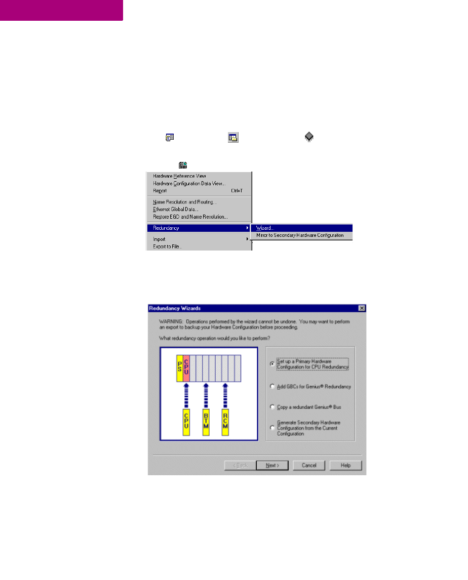
Hardware Configuration (HWC)
52 CIMPLICITY Logic Developer - PLC Version 4.00 GFK-1918D
4
Configuring Redundant Systems
The procedures below are the general steps to follow for configuring redundant
systems. For the procedures on configuring specific redundancy sytems, see the
online help.
To set up the primary hardware configuration for CPU redundancy (Series 90™-70 only)
1. In the Project tab of the Navigator, expand the target node for which you want to set up CPU
redundancy.
2. Right-click Hardware Configuration, point to Redundancy, and choose Wizard.
The Redundancy Wizards dialog box opens, with the Set up a Primary Hardware
Configuration for CPU Redundancy option selected by default.
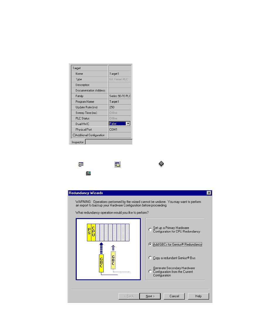
Hardware Configuration (HWC)
GFK-1918D CIMPLICITY Logic Developer - PLC Version 4.00 53
3. Click Next and follow the wizard to the end. The wizard adds a redundant CPU, the Bus Transmitter Module (BTM)
and the Redundancy Communications Module (RCM) to the configuration.
Note: The target property, Dual HWC, is now available in the Inspector and is set
to False.
Adding Genius Bus Controllers (GBC) to your system (PACSystems™ RX7i and Series 90™-70)
1. In the Project tab of the Navigator, expand the target for which you want to set up redundancy.
2. Right-click Hardware Configuration, point to Redundancy, and choose Wizard.
The Redundancy Wizards dialog box appears.
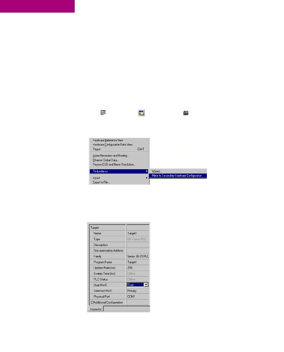
Hardware Configuration (HWC)
54 CIMPLICITY Logic Developer - PLC Version 4.00 GFK-1918D
4
3. Select Add GBCs for Genius Redundancy.
4. Click Next and follow the wizard to the end. The wizard allows you to select a Genius redundancy scheme and the
location of the GBC modules. You can run this wizard multiple times to configure additional pairs of redundant
busses in the same system.
Note: When you add a Genius Bus Controller (GBC) to a Series 90™-70 rack, a
new Genius bus network is automatically created and associated with that slot and
GBC module. Up to 31 Genius I/O devices (blocks) can be connected to a GBC
through its Genius bus.
Configuring the secondary hardware configuration (Series 90™-70 only)
1. In the Project tab of the Navigator, select the Hardware Configuration folder.
2. Right-click Hardware Configuration, point to Redundancy, and choose Mirror to Secondary Hardware
Configuration.
A secondary rack system that is a copy of the primary rack system is generated.
The target now displays two Hardware Configurations (HWCs), one labeled
[Primary] and the other, [Secondary]. The Primary HWC is bolded because it is
currently selected. The target property, Dual HWC, is now set to True.

Hardware Configuration (HWC)
GFK-1918D CIMPLICITY Logic Developer - PLC Version 4.00 55
Note: You can mirror as many times as necessary to synchronize the two HWCs
after modifying the primary HWC. Each time you mirror the primary HWC, the
secondary HWC is updated to reflect those changes.
Series 90™-30: DSM314 Motion Module
The Series 90™-30 supports a module which no other GE Fanuc PLC family
supports: the Motion Mate DSM314 (see page 91). The DSM314 is a high
performance, easy-to-use multi-axis motion control module. Compatible with
Series 90™-30 PLC logic solving and communications functions, the DSM314
supports the following servo types:
■Digital - GE Fanuc digital servo amplifiers and motors.
■Analog - GE Fanuc SL Series analog servos and third-party servos.
The DSM314 Motion module has four axes that can be individually configured in
Standard or Follower mode. It can control up to four analog mode servo axes or up
to two digital mode servo axes. When axis one and two are controlling digital
mode servos, axis three can control an analog servo.
In order to perform motion programming in Logic Developer - PLC, you must have
a DSM314 motion module properly configured (see page 91).
To add a DSM314 motion module
1. With a rack of the Hardware Configuration node expanded, right-click the empty slot you want to add a
DSM314 motion module to and choose Add Module.
The Module Catalog dialog box appears.
2. On the Module Catalog dialog box, click the Motion tab.
A selection of motion modules appears in the Module Catalog dialog box.
Want to know more?
In the Help Index, look up “Redundancy”.
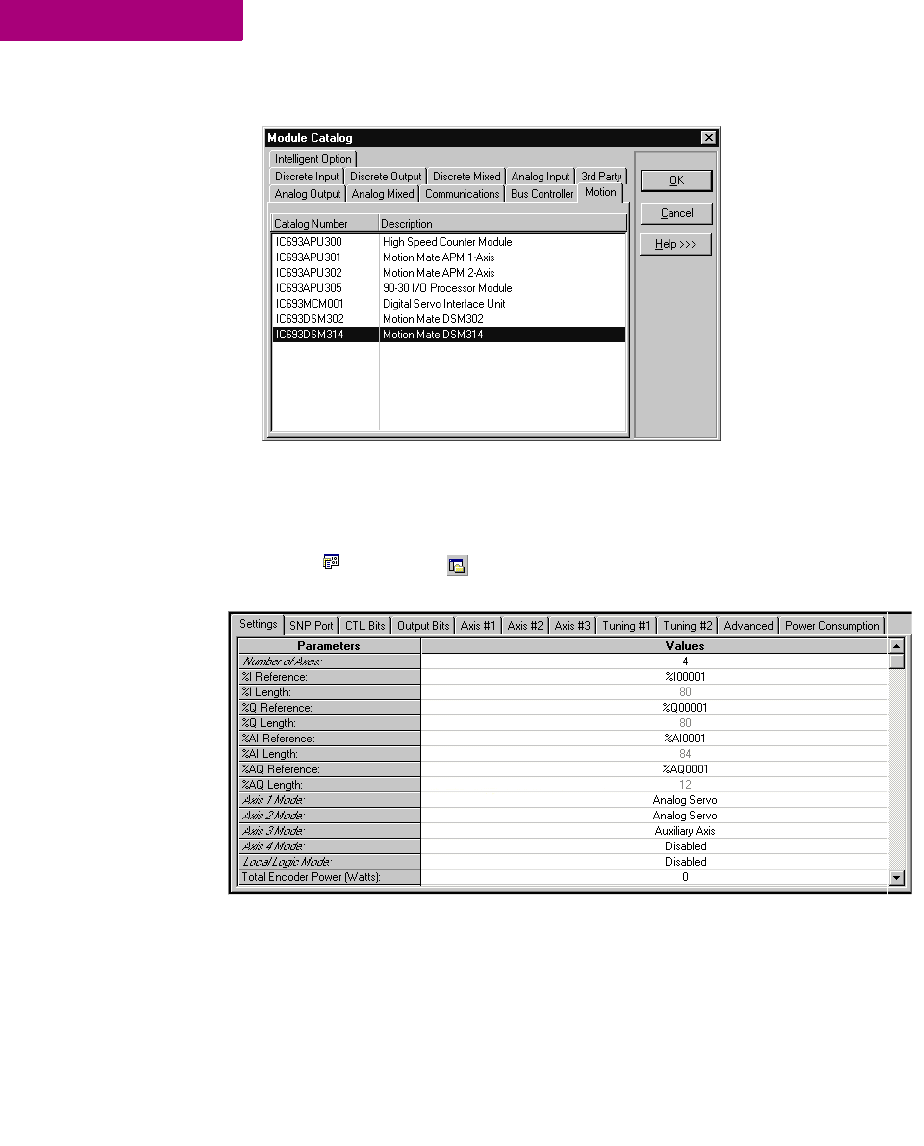
Hardware Configuration (HWC)
56 CIMPLICITY Logic Developer - PLC Version 4.00 GFK-1918D
4
3. From the list, select Motion Mate DSM314.
4. Click OK.
A DSM314 is added to the hardware configuration of your project.
To configure a DSM314
1. In the Project tab of the Navigator, double-click the slot containing a Motion Mate DSM314.
The Parameter editor appears.
2. Configure the DSM314 by using the Parameter editor.
Note: For details on configuring the DSM314, see GFK-1742, Motion Mate
DSM314 for Series 90-30 PLCs Users Manual .
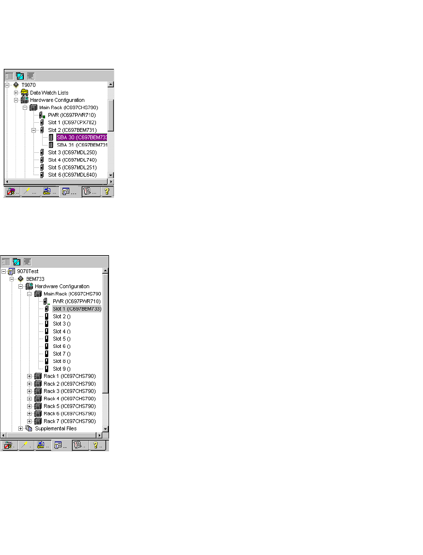
Hardware Configuration (HWC)
GFK-1918D CIMPLICITY Logic Developer - PLC Version 4.00 57
Series 90™-70 Genius Remote I/O Scanner
A Remote I/O Scanner (IC697BEM733) is a Genius device that is part of a Genius
Bus system. As such, it is added as a Genius device to the Genius Bus Controller
(GBC) and it is represented in Logic Developer - PLC by an SBA node under the
GBC node in a Series 90™-70 target.
A Remote I/O Scanner resides in Slot 1 of the main rack of a Series 90™-70 PLC.
I/O modules can be inserted into the other slots of the main rack and on all the
slots of the other racks. As such, the Remote I/O Scanner is represented by a target
in the Project tab of the Navigator, and is also represented by a module in slot 1 of
the main rack of that target.
Navigator: Series 90™-70 Remote
I/O Scanner as a Genius device under
a GBC
Navigator: Series 90™-70
Remote I/O Scanner
as a target and
as a module in Slot 1 of the main rack

Hardware Configuration (HWC)
58 CIMPLICITY Logic Developer - PLC Version 4.00 GFK-1918D
4
To set up a Remote I/O Scanner
1. Add the Remote I/O Scanner as a Genius device to the GBC.
2. When prompted to add a new target for the Remote I/O Scanner, click Yes.
Logic Developer - PLC automatically sets up some of the properties that link the
Remote I/O Scanner to its GBC.
3. Set up the SBA to the same value to the Remote I/O Scanner as a target and to the Remote I/O Scanner as a Genius
Device.
Now whenever you update the I/O map on the Remote I/O Scanner, the I/O map is
automatically updated to the GBC.
4. Configure the Remote I/O Scanner’s target properties.
5. Add and configure the I/O on the Remote I/O Scanner’s rack system.
6. Configure the Remote I/O Scanner’s module properties.
7. Configure the properties of the Remote I/O Scanner as a Genius bus device.
Want to know more?
In the Help Index, look up “
IC697BEM733
, Remote I/O Scanner”.
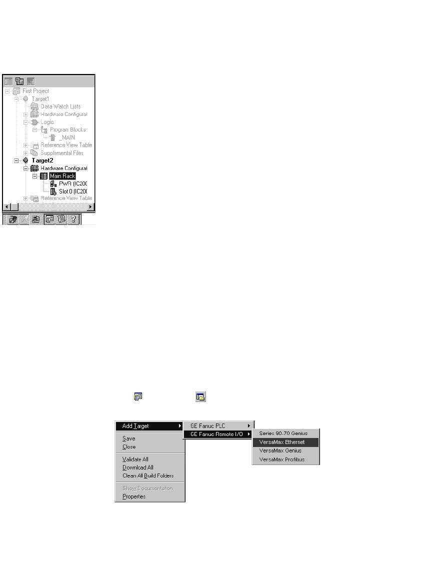
Hardware Configuration (HWC)
GFK-1918D CIMPLICITY Logic Developer - PLC Version 4.00 59
VersaMax Remote I/O
VersaMax remote I/O consists of a Network Interface Unit (NIU) (Ethernet, Genius
or Profibus), and one or more I/O modules. If your target type is remote I/O, you
can use Logic Developer - PLC to configure this hardware. Once configured, the
remote I/O can be controlled from a PLC or PC controller. The differentiating factor
between a VersaMax remote I/O and a PLC is that a remote I/O is simply an
input/output device with a communication interface. Unlike a PLC, a remote I/O
has no CPU.
When working with the VersaMax Remote I/O hardware configuration, Logic
Developer - PLC enables you to add racks, configure the power supply and
configure modules.
Remote I/O targets are generally added to a project when you create a project with
a template (see page 12). You can add additional Remote I/O targets later.
To create a project containing a GE Fanuc Remote I/O target from a template
1. From the File menu, choose New Project.
The New Project dialog box appears.
2. From the Project Template list, choose the GE Fanuc Remote I/O you want to add to your project.
3. Enter a descriptive Project Name.
4. Click OK.
A new Remote I/O project is started.
To add a GE Fanuc Remote I/O target to an existing project
1. In the Project tab of the Navigator, right-click the Project node.
2. Point to Add Target, then to GE Fanuc Remote I/O, and choose the remote I/O you want to add.
Note: The Series 90-70 Genius option is a Series 90™-70 Remote I/O Scanner (see
page 57).
Navigator: VersaMax Remote I/O
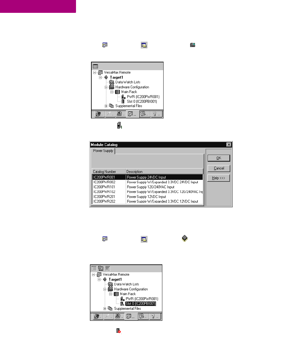
Hardware Configuration (HWC)
60 CIMPLICITY Logic Developer - PLC Version 4.00 GFK-1918D
4
To replace the power supply for your remote I/O configuration
1. In the Project tab of the Navigator, expand the Hardware Configuration node of the remote I/O.
The Navigator displays the following:
2. Right-click the PWR node and choose Replace Module.
The Module Catalogue dialog box appears:
3. From the list, select the power supply that you want to configure for your system.
To add a new Carrier/Base to your VersaMax Remote I/O
1. In the Project tab of the Navigator, select a remote I/O target.
2. Expand the Hardware Configuration node and the Main Rack node.
The Navigator displays the following:
3. Right-click the Slot 0 node and choose Add Carrier/Base.
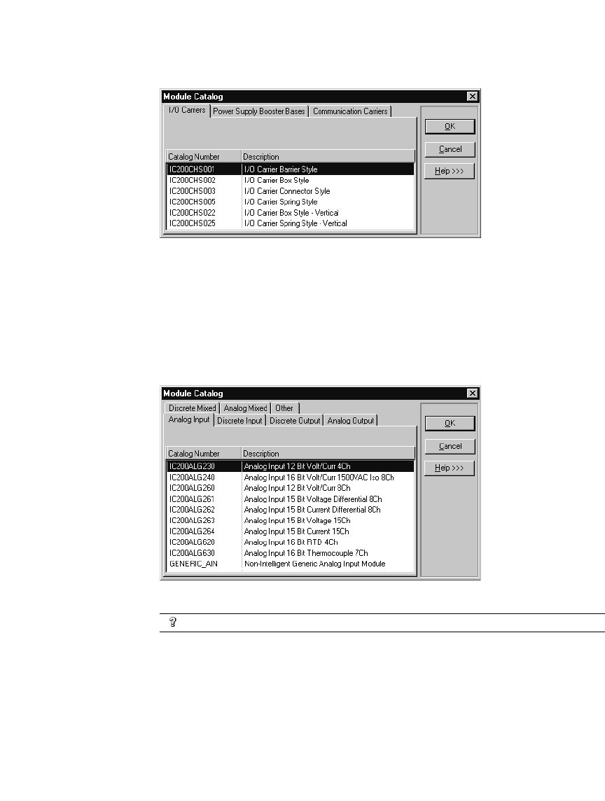
Hardware Configuration (HWC)
GFK-1918D CIMPLICITY Logic Developer - PLC Version 4.00 61
The Module Catalog dialog box appears.
4. Select the carrier/base that you want to add to the remote I/O target.
Note: You can add a maximum of eight carrier modules to each VersaMax® rack.
5. Click OK.
To add a module to a carrier/base
1. Double-click an empty carrier/base.
The Module Catalog appears.
2. From the Module Catalog list, select the module that you want to install.
Want to know more?
In the Help Index, look up “Hardware Configuration”.

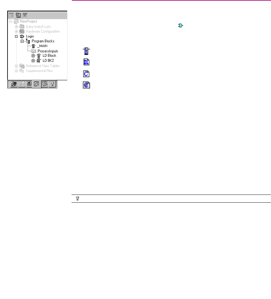
CIMPLICITY Logic Developer - PLC Version 4.00 63
5
Logic Editors
The following logic types are supported by Logic Developer - PLC (not including
motion programming) and are compiled and downloaded to the PLC represented
by the associated GE Fanuc PLC target. The Logic folder of a GE Fanuc PLC
target includes:
■Ladder Diagram (LD) Blocks
■Instruction List (IL) Blocks
■C Blocks
■C programs
These items will be downloaded to, and run on, the target. Each block and user
program is a named section of executable code. Blocks can be grouped under
user-defined folders in the Program Blocks folder. C programs are grouped under
the main Logic folder.
Each target must contain one block or user program named “_MAIN”. On any
target except a release 6 or later Series 90™-70 PLC, the _MAIN block is first to
execute when the project is downloaded to a PLC.
Depending on the type of target PLC, blocks other than”_ MAIN” can be
scheduled for execution based on timer or I/O interrupts.
Note: On release 6 or later of Series 90™-70 PLCs, the LD program can be
scheduled. That is, the Series 90™-70 PLC does not necessarily execute the
_MAIN LD block first.
Want to know more?
In the Help Index, look up “LD Program”.
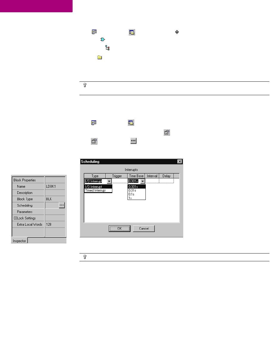
Logic Editors
64 CIMPLICITY Logic Developer - PLC Version 4.00 GFK-1918D
5
To create a user-defined folder
1. In the Project tab of the Navigator, expand the target with the logic you want to organize and then
expand the Logic folder.
2. Right-click the Program Blocks folder, point to New, and choose Folder.
A new user-defined folder appears with a default name.
3. Optionally enter a new folder name, which must be unique among the folders directly under the Program Blocks
folder.
To schedule execution of a logic block
1. In the Project tab of the Navigator, right-click an existing LD, C or IL block, and choose Properties.
The block’s properties appear in the Inspector.
2. In the Inspector, click the button in the Scheduling property.
The Scheduling dialog box appears.
3. Configure scheduling by entering values in each of the fields.
Want to know more?
In the Help Index, look up "PLC" then choose “Organizing Your PLC
Logic”.
Want to know more?
In the Help Index, look up “Scheduling.”
Inspector: IL, LD, C properties

Logic Editors
GFK-1918D CIMPLICITY Logic Developer - PLC Version 4.00 65
To set access control
1. Right-click an LD, IL or C Block and choose Properties.
2. In the Inspector, expand the Lock Settings property.
3. In the Lock Type property, choose a setting from the list.
4. In the Password property, enter a password.
To search/replace in one block
1. Double-click an LD or IL block to open it.
2. From the Search menu, choose Find or Replace.
A dialog box appears.
3. In the Find what or in the Text to find field, enter the text to find.
4. (Only if you want to replace text) In the Replace with field or in the New text field, enter the text to replace the
found text with.
5. Select or clear each search/replace option, as required.
6. Click Find, Find next, Replace, Replace All, Close, or Cancel, as required.
Note: Logic Developer - PLC provides the capability to search for some text in an
entire target or portions thereof, which you can specify. Various options are
available to narrow a search.
Want to know more?
In the Help Index, look up “Global” and select the “Conducting a Global
Search” help topic.
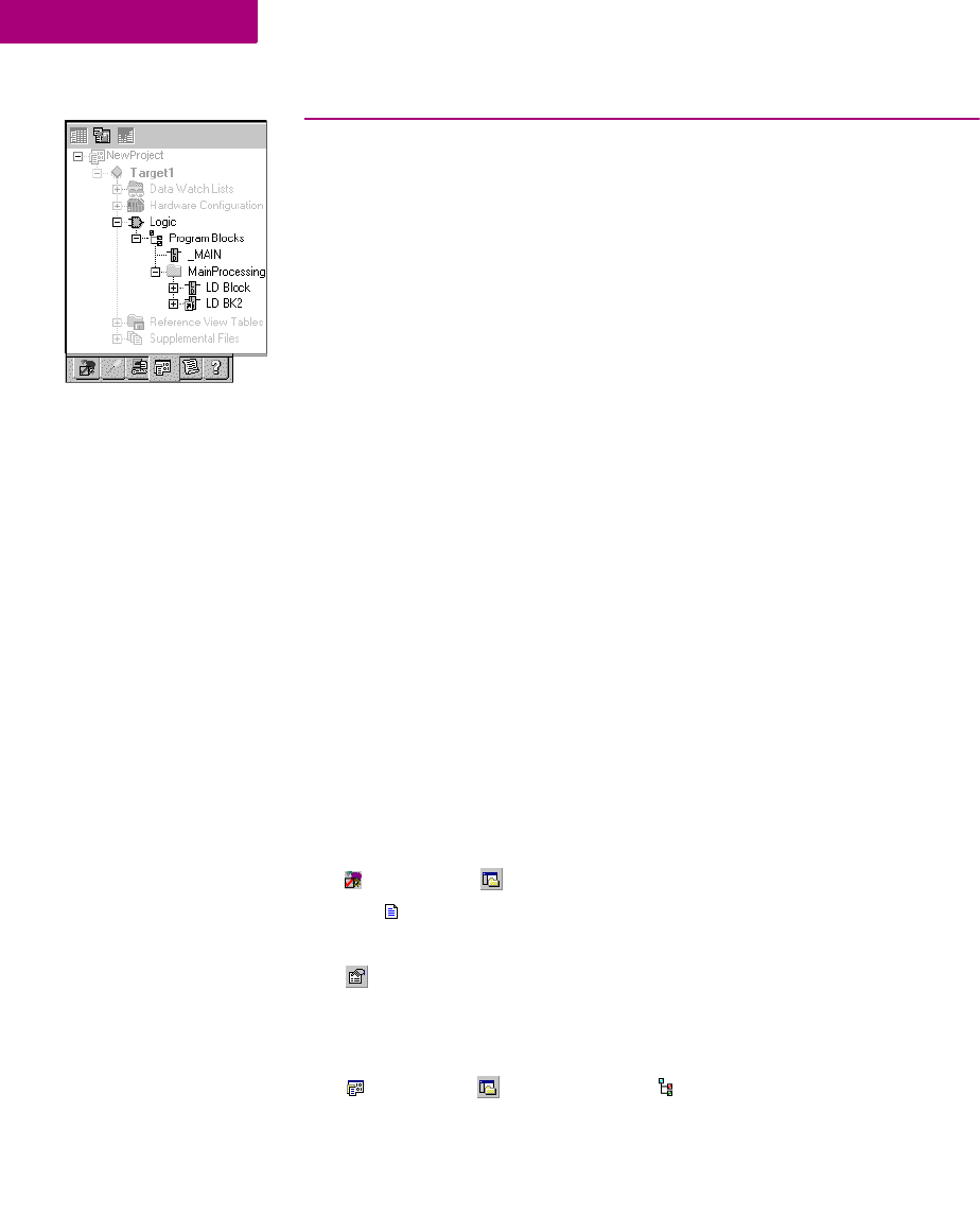
Logic Editors
LD Editor
66 CIMPLICITY Logic Developer - PLC Version 4.00 GFK-1918D
5
LD EDITOR
The Ladder Diagram (LD) editor is used to create programs with the Ladder
Diagram programming language. LD logic graphically represents the programmed
actions performed by a PLC as it executes.
The LD editor is cell-based with rungs constructed of horizontal sequences of
instructions that are wired together. A given instruction and its operands can
occupy one or more cells.
You can work with the LD editor while offline to edit a disk copy of a project, or
while online to monitor the execution of the logic while you fine tune the project
by making word-for-word changes (see page 73).
You can customize the appearance and behavior of the LD editor.
An LD block is a named section of LD Logic that is compiled and downloaded to
the PLC represented by the associated target. The following table describes the
number of blocks supported by each CPU type for a given target.
To customize the LD editor
1. In the Options tab of the Navigator, expand the Editors folder and then the Ladder folder.
2. Right-click a page (Confirmations, Editing, Font and Colors, or View), and choose Properties.
The configurable settings appear as properties in the Inspector.
3. In the Inspector, adjust settings as required.
To create an LD block
1. In the Project tab of the Navigator, right-click the Program Blocks folder point to New, and then
choose LD Block.
CPU Type Number of Blocks Maximum Number of
Blocks
VersaMax
64 subroutine blocks plus one
_MAIN block
65
Series 90™-30
64 subroutine blocks plus one
_MAIN block
65
Series 90™-70
255 subroutine blocks plus one
_MAIN block
256
PACSystems™
511 subroutine blocks plus one
_MAIN block
512
Navigator: Project tab
An LD Block
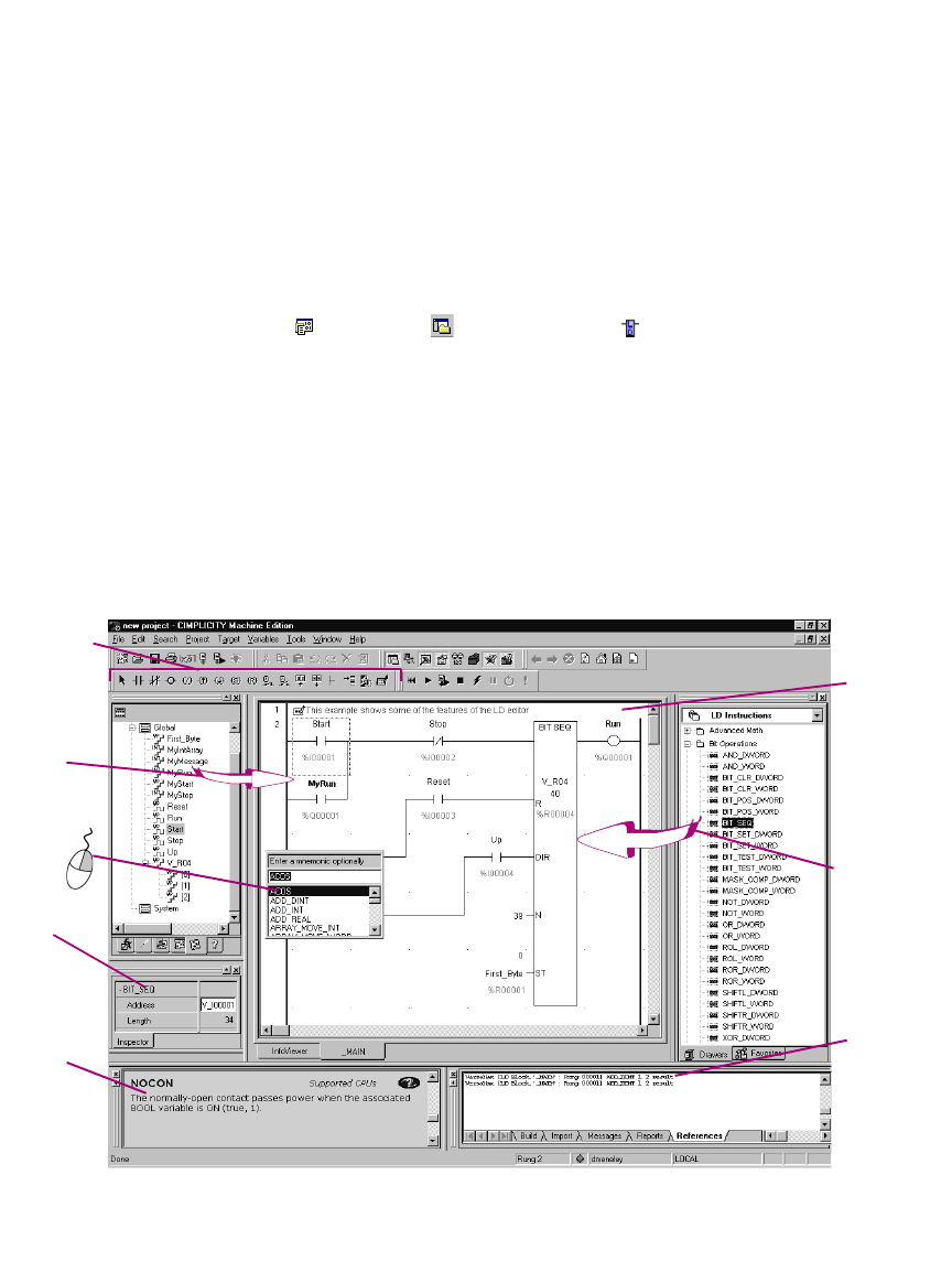
Logic Editors
LD Editor
GFK-1918D CIMPLICITY Logic Developer - PLC Version 4.00 67
A new LD block with a default name is created.
Note: If you use a template or add a target, the first block added to a target is
named “_MAIN” and subsequent blocks added are named LDBK1, LDBK2, and so
on, by default.
2. Rename the block as desired.
To open an LD block for editing
•In the Project tab of the Navigator, double-click an LD block.
The block opens in the LD editor.
Note: You can have multiple blocks open for editing. To navigate to another open
LD block, click the tab that displays its name at the bottom of the editor window.
Working with the LD Editor Offline
While in offline mode, there is no live communication between the LD editor and
the target. Most logic development is done while offline. The following diagram
illustrates some of the more common operations you can perform using the ladder
editor offline.
Drag variables to
instruction
operands to assign
them.
Right-click to
insert an
instruction.
Displays a
list of the
places the
selected
variable is
used in the
References
tab of the
Feedback
Zone.
T
he Companion
tracks your
moves and
provides
information on
w
hat you click.
Use the
Inspector to
configure
address and
length for
instructions
Drag LD
instructions
from the
Toolchest.
Insert common
instructions and
wiring with the
ladder instruction
toolbar.
In-place editor
comment rungs.
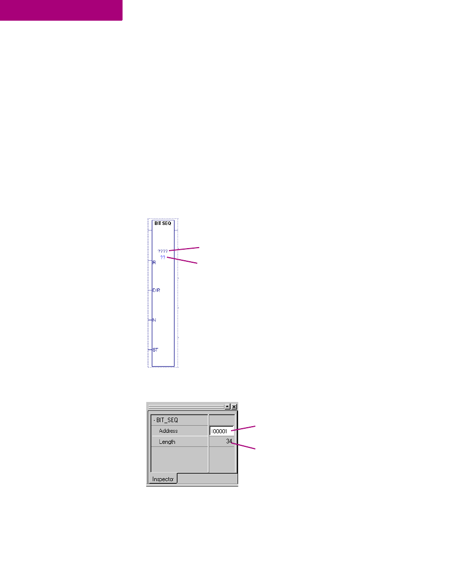
Logic Editors
LD Editor
68 CIMPLICITY Logic Developer - PLC Version 4.00 GFK-1918D
5
To insert an instruction
1. In the LD editor, right-click an empty cell and choose Place Instruction.
A smart list appears listing all available instruction mnemonics.
2. Choose an instruction mnemonic from the list and press ENTER.
Note: Only functions that have no inputs can be placed in the first column.
To configure an instruction’s address and length properties
There are two methods to configure an instruction’s address and length properties.
First method
1. In the LD editor, insert an instruction that requires Address and/or Length configuration.
2. Right-click the instruction and choose Properties.
The Inspector displays the instruction’s properties.
3. In the Address property, enter a variable name or a reference address to specify the start of a memory block.
Note: If you type a reference address, it is converted to a variable name
automatically.
4. In the Length property, enter the number of PLC registers that the instruction requires in the memory block.
Four question marks correspond to the
Address property
Two question marks correspond to the
Length property.
Address Field
Length Field
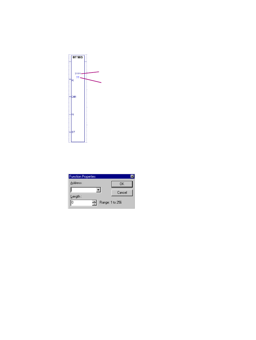
Logic Editors
LD Editor
GFK-1918D CIMPLICITY Logic Developer - PLC Version 4.00 69
Second method
1. In the LD editor, insert an instruction that requires Address and Length configuration.
2. Double-click the instruction or select it and press ENTER.
The Function Properties dialog box appears.
3. In the Address property, enter a variable name or a reference address to specify the start of a memory block.
Note: If you type a reference address, it is converted to a variable name
automatically.
4. In the Length property, enter the number of PLC registers that the instruction requires in the memory block.
Four question marks correspond to the
Address property
Two question marks correspond to the
Length property.
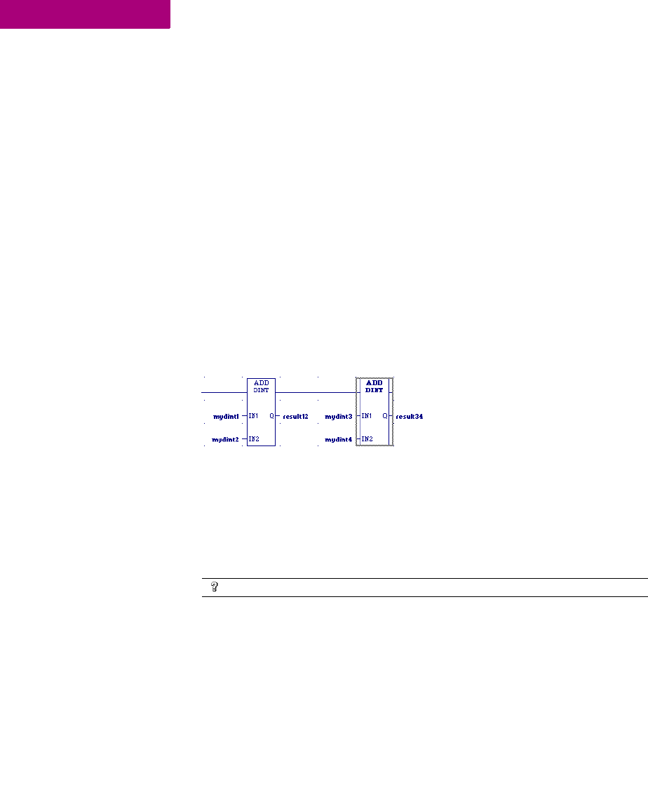
Logic Editors
LD Editor
70 CIMPLICITY Logic Developer - PLC Version 4.00 GFK-1918D
5
To assign variables to instruction operands
1. In the LD editor, double-click beside any operand of an instruction, or click there and press ENTER.
A smart list appears prompting you to enter a variable name or reference address.
Note: If the smart list that appears prompts you for a mnemonic, supply a contact
or a wire.
2. Type, or choose from the list, a variable name or reference address.
If you enter a reference address, a variable name will be automatically substituted.
Editing Logic as Text
You can enter LD logic into the LD editor by starting to type right into a cell. The
smart list will appear and you can contirue type your instructions and operands.
When you press ENTER, the logic you typed will appear in customary graphic form
in the LD editor. For example, in the first cell of a new rung, if you type AD
MyDint1 MyDint2 Result12;AD MyDint3 MyDint4 Result34, the following logic
will appear in the LD editor:
A horizontal wire was inserted in the first cell to make room for the ADD_DINT
insturction’s operands and the operands were inserted in their proper places. In the
keyboard entry, "AD" stood for "ADD_DINT", because it was the first available
instruction that begins with "AD" in the smart list. A semicolon separates the
ADD_DINT instructions. The required horizontal wires are supplied
automatically..
A powerful extension of typing logic into the LD editor is the ability to write LD
logic in any text editor and copy and paste it into the LD editor, or to copy and
paste logic from the LD editor to a text editor. You can copy an entire block of LD
logic from the Navigator to any text editor, or copy sections of LD logic as text
from the LD editor to any text editor. You can then edit the logic in the text editor
and copy the edited logic back into the LD editor.
Want to know more?
In the Help Index, look up “Keyboard Method”.

Logic Editors
LD Editor
GFK-1918D CIMPLICITY Logic Developer - PLC Version 4.00 71
When LD logic is copied as text, a verbose format is used to make it easier to read,
but when you edit the logic as text you can use the same shorthand used in the
keyboard method of entering LD logic in the LD editor.
To copy an entire LD block as text
1. Validate the target to ensure that the LD block contains only valid logic.
2. In the Project tab of the Navigator, expand the target and expand the Logic folder.
3. Expand the Program Blocks folder and, if the LD block is in a user-defined folder, expand the user-defined
folder.
4. Right-click the LD block and choose Copy.
The contents of the LD block are copied to the Windows Clipboard.
5. Paste the contents of the Windows Clipboard into your text editor.
The LD logic is pasted as text.
To copy a section of LD logic as text
1. Validate the target to ensure that the LD block contains only valid logic.
2. In the LD editor, select the cells that contain the logic you want to copy as text.
3. Right-click the selected logic and choose Copy.
The LD logic is copied to the Windows Clipboard.
4. Paste the contents of the Windows Clipboard into your text editor.
The LD logic is pasted as text.
To copy text into the LD editor
1. In the text editor, select and copy the LD logic to the Windows clipboard.
2. In the LD editor, do one of the following:
■Select the cells that you want to overwrite.
- OR -
■Click the cell that will be the upper left corner of the LD logic you want to
paste.
3. Right-click and choose Paste.
Existing cells in the LD editor are overwritten with the contents of the Windows
clipboard.
Want to know more?
In the Help Index, look up “Copying LD Logic as Text: Overview”.

Logic Editors
LD Editor
72 CIMPLICITY Logic Developer - PLC Version 4.00 GFK-1918D
5
Working with the LD Editor Online
In online mode, there is a live communication connection to the target PLC
enabling increased interaction with Logic Developer - PLC.
While online, the LD editor animates the LD logic to reflect program execution in
the target PLC. Data values change in real time while coils and contacts indicate
power flow. Many GE Fanuc targets also supports Run Mode Store (RMS), that is,
they support the downloading of logic to a running target.
Three methods are at your disposal to make changes in your LD logic and
download the changes to an online running PLC:
■Online Editing (PACSystems™ only): While you make your changes in your
logic, the LD editor displays both the original logic and the modified logic, and
the PACSystems™ executes the original logic. You can test your changes online,
and the PACSystems™ retains an inactive copy of the original logic while
executing the modified logic. You can then commit the modified logic
permanently to the PACSystems™, or make the PACSystems™ revert back to
the original logic, or cancel the test and continue editing the logic before testing
the logic again or abandoning the modified logic.
■Word-for-word changes: Changes in the logic made while online that fit in the
same amount of memory as the original logic. For example, changing an
operand is usually a word-for-word change. You can make a word-for-word
change and download it to the PLC while online without having to download
all the logic.
■Other logic changes: Changes in the logic that do not fit in the same amount of
memory as the original logic, for example, adding a new function in a rung or
adding a new rung. Once you have completed a change, you can write the
modified logic to the PLC while it is still running. (For some types of changes,
you must stop the PLC and then download to it.)
To go online to a target PLC
•In the Project tab of the Navigator, right-click the Target and choose Go Online.
The grey target icon turns green to indicate that it is online. The status bar is
updated to reflect the online status. The LD editor, if equal to the PLC, displays
various online features, as shown in the following illustration:
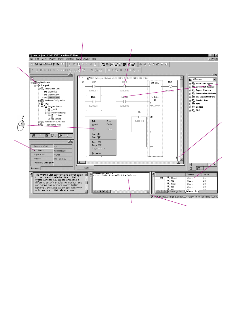
Logic Editors
LD Editor
GFK-1918D CIMPLICITY Logic Developer - PLC Version 4.00 73
Word-for-Word Changes
Word-for-word changes may be completed online to PACSystems™, Series 90™-
30, Series 90™-70, Series 90™ Micro, and VersaMax® modular PLCs. (VersaMax
Nano/ Micro PLCs do not support word-for-word changes.)
Several of the changes to the program that do not modify its size are considered
word-for-word changes. Examples include changing the type of contact or coil, or
changing a reference address used for an existing function block.
To make word-for-word changes
1. While online to a target PLC, make a change to LD logic that does not change the logic size.
You are prompted to download the change.
Online Status
is indicated
by the color
of the target
icon.
R
ung
N
um
b
er
State Flow is indicated by bolded lines.
Monitor and change
values in real-time
with the Data Watch
tool.
Feedback Zone
A red, underlined
variable indicates that
it has been forced ON.
PLC status is indicated
in the status bar.
Right-click a
variable to
force it.
PLC status
and sweep
time are
displayed in
real-time in
the Inspector.
Online indicator

Logic Editors
LD Editor
74 CIMPLICITY Logic Developer - PLC Version 4.00 GFK-1918D
5
2. Click Yes.
The changes are written to the PLC.
Writing Changes to a Target PLC
If you change the size of the program, you must write the changes to the PLC to
maintain equality. You can do so whether the target is running or not. All PLC
families support this run-mode store capability, but not every PLC in every family.
To write changes to the target PLC
1. While online to a target, make a change to LD logic.
2. In the Project tab of the Navigator, right-click the target, point to Online Commands, and choose
Write Changes.
New logic is immediately written to the PLC without stopping the PLC. If the LD
logic was altered, other than a word-for-word change, you are prompted to
download to the running PLC. The entire target is validated, but only the changed
blocks are downloaded.
To turn on/off or force a variable
•In the LD editor, right-click a BOOL variable anywhere in LD logic and choose Force ON, Force OFF, Turn ON, or
Turn OFF.
Note: Forcing a variable ON or OFF overrides any actions the application may
take during runtime. That is, if a variable is forced OFF (0), but LD logic is trying to
turn it ON (1), it stays OFF.
Want to know more?
In the Help Index, look up “Online Editing: an Overview” and “working
online with LD editor: overview".

Logic Editors
LD Editor
GFK-1918D CIMPLICITY Logic Developer - PLC Version 4.00 75
LD Functions
The following is a list of all LD functions available in Logic Developer - PLC. An
asterisk followed by the letter P (*p) indicates the functions exclusive to
PACSystems™ PLCs. An asterisk followed by "70" (*70) indicates the functions
exclusive to Series 90™-70 PLCs. A simple asterisk (*) indicates the functions
shared by PACSystems™ and Series 90™-70 PLCs and exclusive to them.
Companion help indicates which PLCs support the other functions.
Advanced Math
Bit Operations
Coils
Contacts
Want to know more?
In the Help Index, look up “LD Functions”.
ACOS COS LN SQRT_DINT TAN
ASIN EXP LOG SQRT_INT
ATAN EXPT SIN SQRT_REAL
AND_DWORD* BIT_SET_DWORD* NOT_WORD SHIFTL_DWORD*
AND_WORD BIT_SET_WORD OR_DWORD* SHIFTL_WORD
BIT_CLR_DWORD* BIT_TEST_DWORD* OR_WORD SHIFTR_DWORD*
BIT_CLR_WORD BIT_TEST_WORD ROL_DWORD* SHIFTR_WORD
BIT_POS_DWORD* MASK_COMP_DWORD ROL_WORD XOR_DWORD*
BIT_POS_WORD MASK_COMP_WORD ROR_DWORD* XOR_WORD
BIT_SEQ NOT_DWORD* ROR_WORD
COIL NEGCOIL PTCOIL
*p
CONTCOIL NTCOIL
*p
RESETCOIL
NCCOIL POSCOIL SETCOIL
CONTCON LOALR* NOCON POSCON*
FAULT* NCCON NOFLT* PTCON
*p
HIALR* NEGCON* NTCON
*p

Logic Editors
LD Editor
76 CIMPLICITY Logic Developer - PLC Version 4.00 GFK-1918D
5
Control
Conversions
Counters
Data Move
DO_IO EXIT_FOR* PID_ISA SVC_REQ
DRUM FOR_LOOP* SER
END_FOR* PID_IND SUS_IO*
BCD4_TO_INT DINT_TO_BCD8* INT_TO_REAL REAL_TO_WORD UINT_TO_REAL*
BCD4_TO_REAL DINT_TO_INT* INT_TO_UINT* TRUNC_DINT WORD_TO_REAL
BCD4_TO_UINT* DINT_TO_REAL RAD_TO_DEG TRUNC_INT
BCD8_TO_DINT* DINT_TO_UINT* REAL_TO_DINT UINT_TO_BCD4*
BCD8_TO_REAL* INT_TO_BCD4 REAL_TO_INT UINT_TO_DINT*
DEG_TO_RAD INT_TO_DINT* REAL_TO_UINT* UINT_TO_INT*
DNCTR UPCTR
BLK_CLR_WORD BUS_TS_BYTE*
P
DATA_INIT_UINT* SWAP_WORD*
BLKMOV_DINT* BUS_TS_DWORD*
P
DATA_INIT_WORD* VME_CFG_READ
*70
BLKMOV_DWORD* BUS_WRT_BYTE*
P
MOVE_BOOL VME_CFG_WRITE
*70
BLKMOV_INT BUS_WRT_DWORD*
P
MOVE_DINT* VME_RD_BYTE*
70
BLKMOV_REAL BUS_WRT_WORD*
P
MOVE_DWORD* VME_RD_WORD*
70
BLKMOV_UINT* COMM_REQ MOVE_INT VME_RMW_BYTE*
70
BLKMOV_WORD DATA_INIT_ASCII* MOVE_REAL VME_RMW_WORD*
70
BUS_RD_BYTE*
P
DATA_INIT_COMM* MOVE_UINT* VME_TS_BYTE*
70
BUS_RD_DWORD*
P
DATA_INIT_DINT* MOVE_WORD VME_TS_WORD*
70
BUS_RD_WORD*
P
DATA_INIT_DLAN
*70
SHFR_BIT VME_WRT_BYTE*
70
BUS_RMW_BYTE*
P
DATA_INIT_DWORD* SHFR_DWORD* VME_WRT_WORD*
70
BUS_RMW_DWORD*
P
DATA_INIT_INT* SHFR_WORD
BUS_RMW_WORD*
P
DATA_INIT_REAL* SWAP_DWORD*

Logic Editors
LD Editor
GFK-1918D CIMPLICITY Logic Developer - PLC Version 4.00 77
Data Table
Math
ARRAY_MOVE_BOOL FIFO_WRT_WORD* SEARCH_GE_UINT* SEARCH_NE_DINT
ARRAY_MOVE_BYTE LIFO_RD_DINT* SEARCH_GE_WORD SEARCH_NE_DWORD*
ARRAY_MOVE_DINT LIFO_RD_DWORD* SEARCH_GT_BYTE SEARCH_NE_INT
ARRAY_MOVE_DWORD* LIFO_RD_INT* SEARCH_GT_DINT SEARCH_NE_UINT*
ARRAY_MOVE_INT LIFO_RD_UINT* SEARCH_GT_DWORD* SEARCH_NE_WORD
ARRAY_MOVE_UINT* LIFO_RD_WORD* SEARCH_GT_INT SORT_INT*
ARRAY_MOVE_WORD LIFO_WRT_DINT* SEARCH_GT_UINT* SORT_DINT*
ARRAY_RANGE_DINT* LIFO_WRT_DWORD* SEARCH_GT_WORD SORT_WORD*
ARRAY_RANGE_DWORD* LIFO_WRT_INT* SEARCH_LE_BYTE TBL_RD_DINT*
ARRAY_RANGE_INT* LIFO_WRT_UINT* SEARCH_LE_DINT TBL_RD_DWORD*
ARRAY_RANGE_UINT* LIFO_WRT_WORD* SEARCH_LE_DWORD* TBL_RD_INT*
ARRAY_RANGE_WORD* SEARCH_EQ_BYTE SEARCH_LE_INT TBL_RD_UINT*
FIFO_RD_DINT* SEARCH_EQ_DINT SEARCH_LE_UINT* TBL_RD_WORD*
FIFO_RD_DWORD* SEARCH_EQ_DWORD* SEARCH_LE_WORD TBL_WRT_DINT*
FIFO_RD_INT* SEARCH_EQ_INT SEARCH_LT_BYTE TBL_WRT_DWORD*
FIFO_RD_UINT* SEARCH_EQ_UINT* SEARCH_LT_DINT TBL_WRT_INT*
FIFO_RD_WORD* SEARCH_EQ_WORD SEARCH_LT_DWORD* TBL_WRT_UINT*
FIFO_WRT_DINT* SEARCH_GE_BYTE SEARCH_LT_INT TBL_WRT_WORD
FIFO_WRT_DWORD* SEARCH_GE_DINT SEARCH_LT_UINT*
FIFO_WRT_INT* SEARCH_GE_DWORD* SEARCH_LT_WORD
FIFO_WRT_UINT* SEARCH_GE_INT SEARCH_NE_BYTE
ABS_DINT* ADD_UINT* MOD_DINT MUL_REAL SUB_REAL
ABS_INT* DIV_DINT MOD_INT MUL_UINT* SUB_UINT*
ABS_REAL* DIV_INT MOD_UINT* SCALE_INT
ADD_DINT DIV_MIXED* MUL_DINT SCALE_WORD
ADD_INT DIV_REAL MUL_INT SUB_DINT
ADD_REAL DIV_UINT* MUL_MIXED* SUB_INT

Logic Editors
LD Editor
78 CIMPLICITY Logic Developer - PLC Version 4.00 GFK-1918D
5
Program Flow
Relational
Timers
CALL ENDMCR JUMP LABELN V_WIRE
COMMENT ENDMCRN JUMPN MCR
END H_WIRE LABEL MCRN
CMP_DINT* EQ_UINT* GT_REAL LT_INT RANGE_DINT
CMP_INT* GE_DINT GT_UINT* LT_REAL RANGE_DWORD*
CMP_REAL* GE_INT LE_DINT LT_UINT* RANGE_INT
CMP_UINT* GE_REAL LE_INT NE_DINT RANGE_UINT*
EQ_DINT GE_UINT* LE_REAL NE_INT RANGE_WORD
EQ_INT GT_DINT LE_UINT* NE_REAL
EQ_REAL GT_INT LT_DINT NE_UINT*
OFDT_HUNDS ONDTR_HUNDS TMR_HUNDS
OFDT_SEC* ONDTR_SEC* TMR_SEC*
OFDT_TENTHS ONDTR_TENTHS TMR_TENTHS
OFDT_THOUS ONDTR_THOUS TMR_THOUS
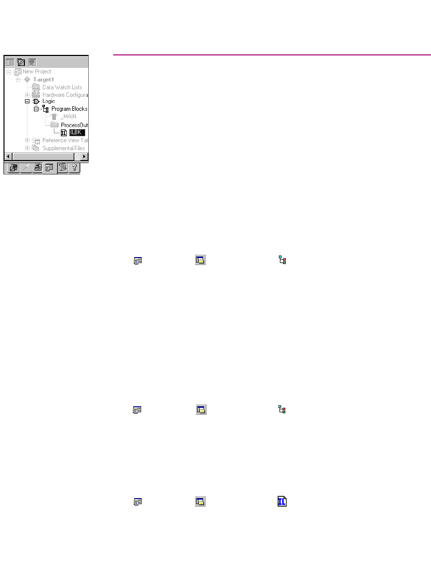
Logic Editors
IL Editor
GFK-1918D CIMPLICITY Logic Developer - PLC Version 4.00 79
IL EDITOR
Instruction List (IL) is a programming language specified by the IEC 61131-3
standard. This text language is accumulator-based and much like the assembly
languages used for programming microprocessors. The instructions executed by
the IL program modify or use an accumulator that is located in PLC memory. Two
types of accumulators are defined: one analog accumulator for numeric and
bitwise operations and eight boolean accumulators for discrete logic to support
eight levels of nested boolean expressions. The IL editor is free-form with an option
to apply a standard formatting rule. The appearance and behavior of the IL editor is
user-configurable.
Note: Only Series 90™-30, VersaMax PLCs, and VersaMax Nano/Micro support IL
logic.
To configure accumulators
1. In the Project tab of the Navigator, right-click the Program Blocks folder and choose Properties.
The Inspector opens, displaying the Accumulator Address properties.
2. In the Boolean Start property, enter the reference address of the first of eight PLC memory locations to use for
boolean accumulators.
The ending address is calculated automatically. The memory area must be %T,
%M, or %Q.
3. In the Analog Start property, enter the PLC memory locations to use for the analog accumulator.
The ending address is calculated automatically. The memory area must be %R,
%AI or %AQ.
To create an IL block
1. In the Projects tab of the Navigator, right-click the Program Blocks folder, point to New, and choose IL
Block.
An empty IL block with the default name ”ILBkn” is added to the folder, where n
represents a unique number.
2. Rename the block as desired.
To open an IL block for editing
•In the Project tab of the Navigator, right-click an IL Block and choose Open.
The block opens in the IL editor.
Navigator: Project tab
An IL Block
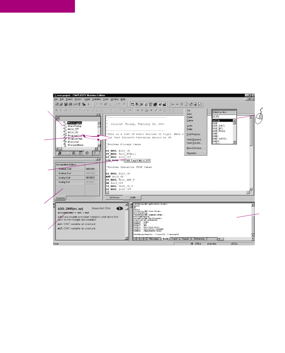
Logic Editors
IL Editor
80 CIMPLICITY Logic Developer - PLC Version 4.00 GFK-1918D
5
Note: You can have multiple blocks open for editing. To navigate to another open
IL block, click the tab displaying its name at the bottom of the editor window.
Working with the IL Editor Offline
Most project development is carried out while offline from the target PLC. Editing
while offline provides maximum flexibility in editing and allows you to interact
with the Machine Edition tools as shown in the following diagram.
To insert an instruction or function
1. In the IL editor, right-click and choose Insert Keyword.
A smart list appears listing all available instruction mnemonics.
2. From the list, select an instruction and press ENTER.
The instruction is inserted in your logic.
To assign operands to an instruction
1. In the IL editor, right-click and choose Insert Variable.
A smart list appears showing all your defined variables.
Right click in
the IL Editor
to insert an
instruction or
variable.
T
he Variables tab of
the Navigator lists all
the variables in your
projects.
A description of a
variable pops up when
you hover the mouse
over it.
The Build tab of the
Feedback Zone lists
error messages
when you validate.
T
he Companion tracks
all of your moves and
provides information
on what you click.
Drag and drop
variables from the
Variables list into the
IL editor.
Configure the
accumulators in the
Inspector.

Logic Editors
IL Editor
GFK-1918D CIMPLICITY Logic Developer - PLC Version 4.00 81
2. Type, or choose from the list, a variable name or reference address and then press ENTER.
The name appears in your logic.
Note: If you entered a reference address or a new variable name, you must create
a variable from it.
To create a variable from a reference address
1. In the IL editor, right-click a reference address, point to Create “name” as, and then choose a data type.
A variable is created and a default name is applied. For example, if the reference
address is %R0032, the auto-created variable is named R00032.
To create a variable from a name
1. In the IL editor, right-click a name, point to Create “name” as, and then choose a data type.
A variable is created with the name you right-clicked.
2. Map the variable to PLC memory. (See page 17.)
To move or duplicate IL logic
1. In the IL editor, select a range of logic.
2. To move it, click the selection and drag it to a new location. To duplicate it, press CTRL while clicking the selection, and
drag the selection to where you want to place the duplicate.
When you release the mouse button, the selection is respectively moved to the
new location or a duplicate copy of the selected logic is placed in the new area.
To insert an inline comment
1. In the IL editor, click where you want to insert an inline comment.
2. Type an apostrophe (‘) followed by comment text.
Press ENTER to complete the comment.
To insert a block comment
1. In the IL editor, click where you want to insert a block comment.
2. Type (* followed by comment text.
A block comment can contain any number of characters and can span multiple
lines.
3. Type *) to complete the block comment.
To reformat IL code
•In the IL editor, right-click and choose Beautify Source.
The entire content of the IL editor is reformatted according to the default formatting
(indentation) rules.
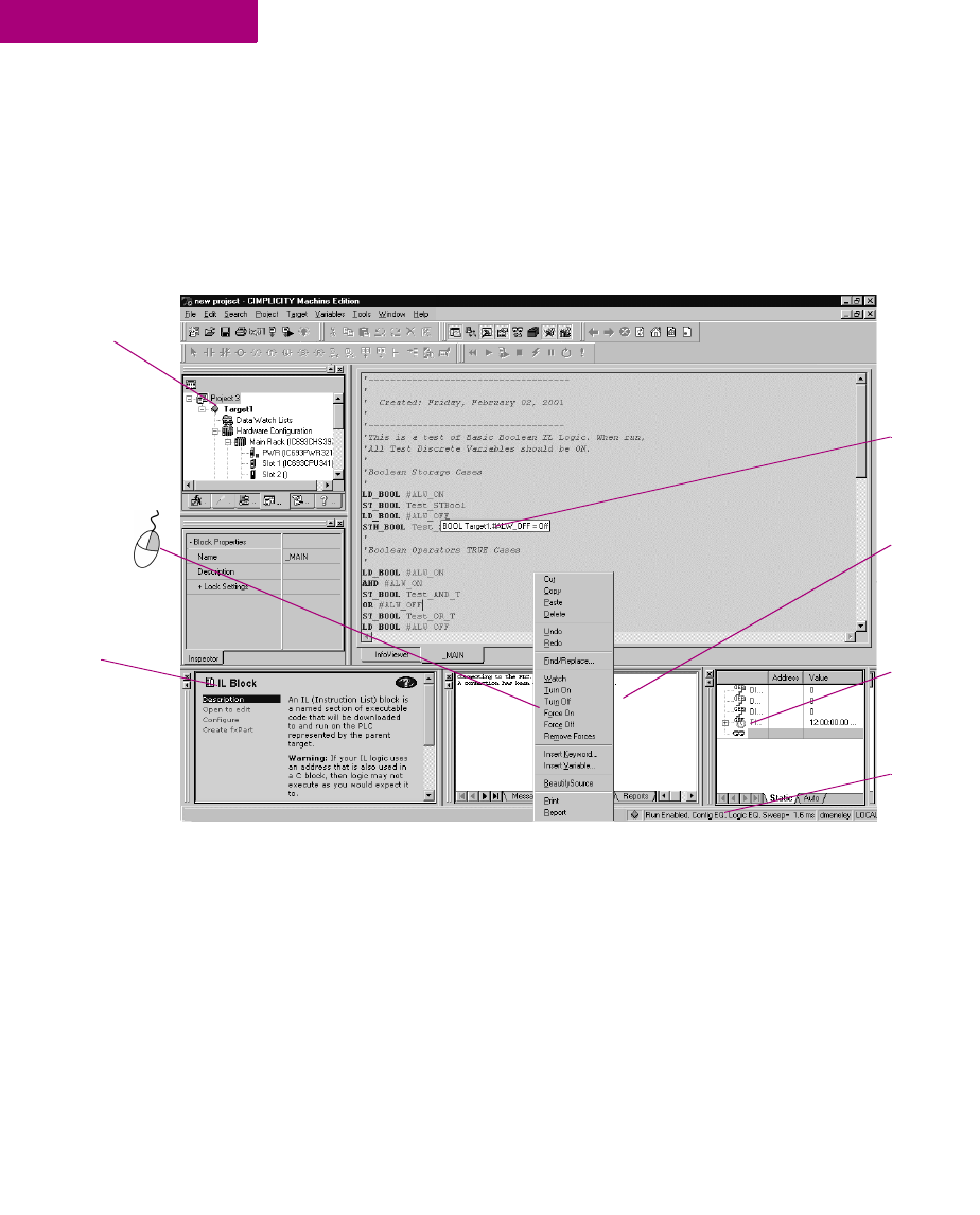
Logic Editors
IL Editor
82 CIMPLICITY Logic Developer - PLC Version 4.00 GFK-1918D
5
Working with the IL Editor Online
While online to a target PLC, the IL editor enables you to edit logic, monitor data
values, and change or force the state of BOOL variables in real-time. This allows
you to test the execution of logic, to trigger an event within an executing project,
or to remove an element from logic execution.
To monitor a data value
•Click anywhere in the IL editor and hover the mouse pointer over a variable.
A tooltip appears, showing the variable’s current value. This value, however, does
not update. You must move the mouse pointer away and back over the variable.
To change a BOOL variable’s state
•In the IL editor, right-click the BOOL variable whose value you want to change and choose Turn On or Turn Off.
The state of the variable in the target PLC changes when the command is received.
It remains in that state until acted on by the PLC’s logic.
The Feedback Zone
indicates that a
connection has been
established with the
PLC.
T
he
Companion
tracks your
moves and
provides
information
on what you
click.
T
arget icon
changes to
indicate
status of the
PLC.
PLC status is
indicated in the
status bar.
Right-click a
BOOL to
change or
force its state.
Hover over a
variable to show a
popup of its value.
Monitor and
change variable
values in the Data
Watch.

Logic Editors
IL Editor
GFK-1918D CIMPLICITY Logic Developer - PLC Version 4.00 83
To force a BOOL variable’s state
•In the IL editor, right-click a BOOL variable and choose Force On or Force Off.
The state of the forced variable will remain unchanged, regardless of any actions
by the PLC’s logic.
To remove the force from a BOOL variable
•In the IL editor, right-click a BOOL variable and choose Remove Forces.
The state of the forced variable will be controlled by the PLC’s logic.
Writing Changes to a Target PLC
You can change your IL logic while online, but you must write the changes to the
PLC to maintain equality. Writing changes to a target PLC requires the PLC to be
online and running.
Note: If you go offline, you can do a regular download.
To write changes to the target PLC (if the target PLC supports it)
1. While online to a target PLC, make a change to IL logic.
2. In the Project tab of the Navigator, right-click the target, point to Online Commands, and choose
Write Changes to PLC.
You are prompted to confirm a Run Mode Store. That is, the altered IL block will be
downloaded to the PLC without stopping the PLC.
Want to know more?
In the Help Index, look up “Writing Changed Logic to the PLC”

Logic Editors
IL Editor
84 CIMPLICITY Logic Developer - PLC Version 4.00 GFK-1918D
5
IL Instructions and Functions
The following is a list of all IL instructions and functions available in Logic
Developer - PLC. An asterisk (*) indicates the functions exclusive to VersaMax®
PLCs. Companion help indicates which PLCs support the other functions.
Basic Instructions
Advanced Math
Bit Operations
Control
Conversions
Counters
ADD CAL GT MOD NT R SUB
AND DIV LE MUL OR RET XORN
AND_WORD EQ LT NE ORN RETC
ANDN GE MCRN NOT PT S
ACOS COS LN SQRT_INT TAN
ASIN EXP LOG SQRT_DINT
ATAN EXPT SIN SQRT_REAL
AND_WORD BIT_SEQ MASK_COMP_DWORD OR_WORD SHIFTL_WORD
BIT_CLR_WORD BIT_SET_WORD MASK_COMP_WORD ROL_WORD
BIT_POS_WORD BIT_TEST_WORD NOT_WORD ROR_WORD
DO_IO PID_ISA
DRUM SER
PID_IND SVC_REQ
BCD4_TO_INT DINT_TO_REAL RAD_TO_DEG REAL_TO_WORD WORD_TO_REAL
BCD4_TO_REAL INT_TO_BCD4 REAL_TO_DINT TRUNC_DINT
DEG_TO_RAD INT_TO_REAL REAL_TO_INT TRUNC_INT
DNCTR UPCTR

Logic Editors
IL Editor
GFK-1918D CIMPLICITY Logic Developer - PLC Version 4.00 85
Data Move
Data Table
Math
Program Flow
Relational
Timers
BLK_CLR_WORD BLKMOV_DINT MOVE_BOOL MOVE_WORD
BLKMOV_INT COMM_REQ MOVE_REAL SHFR_WORD
BLKMOV_REAL MOVE_INT SHFR_BIT
ARRAY_MOVE_BOOL SEARCH_EQ_INT SEARCH_GT_DINT SEARCH_LT_BYTE SEARCH_NE_WORD
ARRAY_MOVE_BYTE SEARCH_EQ_WORD SEARCH_GT_INT SEARCH_LT_DINT
ARRAY_MOVE_DINT SEARCH_GE_BYTE SEARCH_GT_WORD SEARCH_LT_INT
ARRAY_MOVE_INT SEARCH_GE_DINT SEARCH_LE_BYTE SEARCH_LT_WORD
ARRAY_MOVE_WORD SEARCH_GE_INT SEARCH_LE_DINT SEARCH_NE_BYTE
SEARCH_EQ_BYTE SEARCH_GE_WORD SEARCH_LE_INT SEARCH_NE_DINT
SEARCH_EQ_DINT SEARCH_GT_BYTE SEARCH_LE_WORD SEARCH_NE_INT
ADD_DINT DIV_DINT MOD_DINT MUL_DINT SCALE_WORD* SUB_REAL
ADD_INT DIV_INT MOD_INT MUL_REAL SUB_DINT
ADD_REAL DIV_REAL MUL_INT SCALE_INT* SUB_INT
CALL ENDMCR JUMP LABELN V_WIRE
COMMENT ENDMCRN JUMPN MCR
END H_WIRE LABEL MCRN
EQ_DINT GE_DINT GT_DINT LE_DINT LT_DINT NE_DINT RANGE_DINT
EQ_INT GE_INT GT_INT LE_INT LT_INT NE_INT RANGE_INT
EQ_REAL GE_REAL GT_REAL LE_REAL LT_REAL NE_REAL RANGE_WORD
OFDT_HUNDS ONDTR_HUNDS TMR_HUNDS
OFDT_TENTHS ONDTR_TENTHS TMR_TENTHS
OFDT_THOUS ONDTR_THOUS TMR_THOUS
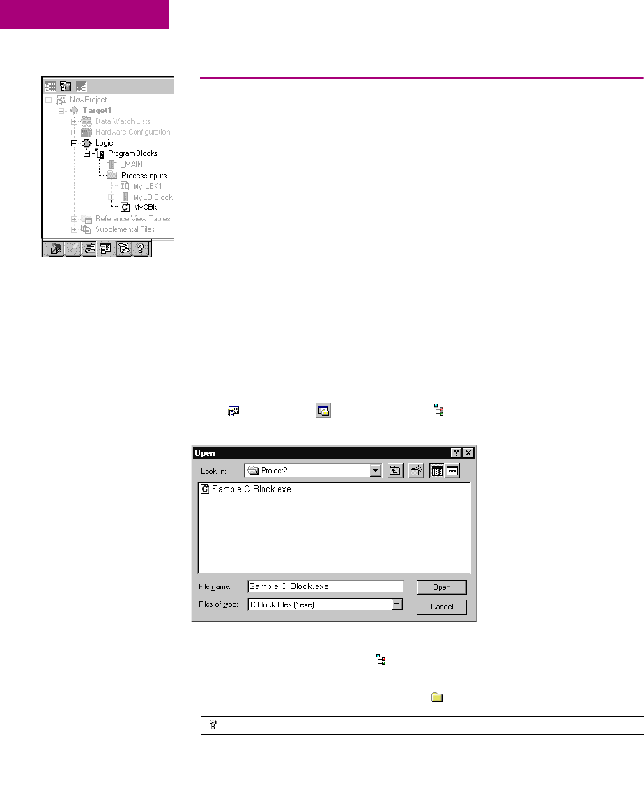
Logic Editors
C Blocks
86 CIMPLICITY Logic Developer - PLC Version 4.00 GFK-1918D
5
C BLOCKS
A C block is an independent section of executable code written in the C
programming language, that is downloaded to and executed on the target PLC. C
blocks are created externally using GE Fanuc’s C Programming Toolkit and then
imported into a project. A C block compiled for PACSystems™ has a .gefelf
extension. A C block compiled for Series 90™-70 or Series 90™-30 has a .exe
extension. C Blocks can be called as a subroutine from another block (LD or IL) but
cannot call another block.
For more information on developing C Blocks, refer to C Programmer’s Toolkit for
Series 90 PLCs (GFK-0646) and PACSystems RX7i C Toolkit User’s Guide (GFK-
2259).
Working with C blocks
To import a C block
1. In the Projects tab of the Navigator, right-click the Program Blocks folder and choose Add C block.
The Open dialog box appears.
2. Browse to the .exe or .gefelf file you want to import and click Open.
The selected file is added to the Program Blocks folder with the same name as
the .exe or gefelf file.
Note: You can then move the C Block to a user-defined folder.
Want to know more?
In the Help Index, choose “C” and "User-Defined Folder".
Navigator: Project tab
A C Block

Logic Editors
C Blocks
GFK-1918D CIMPLICITY Logic Developer - PLC Version 4.00 87
To set a C block’s parameters
Note: This procedure applies only to PACSystems™ and to Series 90™-70 targets
and to C blocks that were written to require parameters.
1. In the Projects tab of the Navigator, right-click the C block and choose Properties.
The Inspector displays the block’s properties.
2. In the Inspector, select the Parameters property and click .
The Parameters dialog box opens.
3. Type a name and description for each required input and output parameter.
For information on the required parameters, consult the written documentation for
the C block. The names you enter will display in the CALL instruction. The names
and descriptions will display as tooltip help when you hover over the CALL
instruction.
Want to know more?
In the Help Index, enter “Parameterized” and select the “C Block” help
topic.
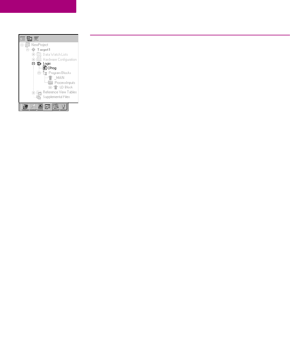
Logic Editors
C Programs
88 CIMPLICITY Logic Developer - PLC Version 4.00 GFK-1918D
5
C PROGRAMS
Note: C programs are supported only on Series 90™-70 CPUs, firmware release
6.00 and later.
A C program is an independent section of executable code, written in C language,
that is downloaded to and executed on the associated target PLC. To develop a C
program, use GE Fanuc's C Programmer's Toolkit for Series 90 PLCs User's Manual
(GFK-0646). You then import it into a project.
A C program has access to all the % reference tables of the PLC except for the
_MAIN LD block’s %P memory and the %L memory of any other LD block. A C
program can also call any of the numerous PLC-embedded function blocks, which
are included in the C Programmer’s Toolkit.
A C program cannot be called as a subroutine. Execution is controlled only
through scheduling. A C program cannot call another block as a subroutine.
By setting the parameters of a C program, you enable it to access memory directly.
When a C program begins to execute, it reads the data for all the parameters and
makes a copy of the data. If the C program’s execution is interrupted or time-sliced
over multiple scans, the C program, when it resumes execution, uses the copy of
the data that it made upon beginning to execute.
You can add C programs to a Series 90™-70 target only if the _MAIN block is an
LD block. The LD program is then treated as a user program, which can be
scheduled. The maximum number of C programs you can add is 15.
If you have State Logic on a Series 90™-70 target, it is compiled into a C Program
called _STATE, whether State Logic coexists with LD logic or not. If State Logic
does not coexist with LD logic, _STATE is the only C program supported by the
target.
C programs can coexist with State Logic on a Series 90™-70 PLC. For such a
target, the State Logic is compiled into a C program. This C program is named
_MAIN if there is no LD logic; however, if State Logic coexists with LD logic, the
State Logic is compiled into a C program named _STATE and one LD block must
be named _MAIN.
User Programs
User programs consists of:
■C programs
■The LD program, if the _MAIN block is an LD block.
Navigator: Project Tab
A C Program

Logic Editors
C Programs
GFK-1918D CIMPLICITY Logic Developer - PLC Version 4.00 89
Working with User Programs
To configure execution scheduling
1. In the Projects tab of the Navigator, right-click a C program or the _MAIN LD block, and choose
Properties.
The Inspector displays the user program’s properties.
2. In the Inspector, expand the Scheduling property.
3. Select a Schedule Mode.
4. Select the other properties used in the schedule mode you selected.
5. Click OK.
Note: If you made any entries, they are checked when you click OK. You must
correct any errors before you can close the dialog box by clicking the OK button.
Setting a C program’s parameters
Note: You must provide a list of all the input and output parameters that the C
program requires. The LD program does not use parameters.
1. In the Projects tab of the Navigator, right-click a C program and choose Properties.
The Inspector displays the C program’s properties.
2. In the Inspector, select the Parameters property and click .
The Parameters dialog box opens.
3. On the Input and Output tabs, enter up to 8 input and up to 8 output parameters. Each parameter has its own row on
the tab. For each parameter, double-click the following cells and enter the required data:
■Name: The parameter’s name.
■Ty p e : The parameter’s data type.
■Length: The length of the input or output reference.
■Variable: The first data item associated with the parameter.
■Description: (Optional) The parameter’s description.
Want to know more?
In the Help Index, choose “C Program”.

CIMPLICITY Logic Developer - PLC Version 4.00 91
6
Motion Programming
Logic Developer - PLC supports motion programming for the Motion Mate
DSM314 motion control module. A high performance, easy-to-use, multi-axis
motion control module, the Motion Mate DSM314 is highly integrated with the
Series 90™-30 PLC logic solving and communication functions.
The DSM314 (see page 55) supports 10 motion programs, 40 subroutines and a
maximum total of 1000 motion program statements. Logic Developer - PLC,
making motion programming possible, supports the following motion editors:
PLC Motion Editor
Local Logic Editor
CAM Editor
This chapter outlines basic procedures that will get you started with Logic
Developer - PLC to create motion programs, using these three motion editors.
To add a Motion component to a target
•In the Project tab of the Navigator, right-click the target, point to Add Component and then choose
Motion.
A Motion Program node is added to your project. Included are empty
Motion Blocks, Local Logic, CAM Profiles and CAM Blocks folders.
Navigator: Project tab
Motion Program nodes
Target right-click menu
Motion Programming
PLC Motion Editor
92 CIMPLICITY Logic Developer - PLC Version 4.00 GFK-1918D
6
PLC MOTION EDITOR
Logic Developer - PLC includes a PLC Motion Editor, which enables you to create
PLC Motion blocks for the DSM314. This text-based editor is configurable as to its
appearance and behavior. Comments and white space are not considered as PLC
Motion program statements. Motion programming has a different programming
syntax from Local Logic.
To add a Motion Block
1. In the Project tab of the Navigator, expand the Motion Program folder.
2. Right-click the Motion Blocks folder and choose New.
A new empty PLC Motion block with a default name is added to your project.
3. Rename the block as desired.
To open a motion block for editing
•In the Project tab of the Navigator, right-click the Motion Block node and choose Open.
The block opens for editing in the PLC Motion editor
Navigator: Project tab
Motion Blocks
Motion Programming
PLC Motion Editor
GFK-1918D CIMPLICITY Logic Developer - PLC Version 4.00 93
Working with the Motion Editor
To insert a command
1. In the Motion editor, right-click and choose Insert Keyword.
A smart list appears showing all available motion commands.
2. Select the appropriate command from the smart list and press ENTER.
The command is placed in the motion editor.
Want to know more?
In the Help Index, choose “PLC Motion Editor”.
Insert a PLC Motion
command by
choosing a keyword.
Insert a PLC Motion
variable by selecting
a variable from the
smart list.
The Companion
tracks all mouse
clicks.
The Feedback Zone
indicates that a
connection has been
established with the
PLC.

Motion Programming
PLC Motion Editor
94 CIMPLICITY Logic Developer - PLC Version 4.00 GFK-1918D
6
Motion Commands
ACCEL The ACCEL statement sets the axis acceleration for subsequent moves
and remains in effect in a given program unless changed. Note: If a
move instruction is executed before ACCEL, the tag Acceleration is
used.
BLOCK NUMBER Block numbers may be used as the destination of JUMP commands.
Block numbers must be unique and can be between 1 and 65535.
CAM The CAM statement starts CAM motion and specifies exit conditions.
CAM-LOAD CAM-LOAD loads a parameter register with the starting location for a
CAM slave axis.
CAM-PHASE CAM-PHASE sets the phase for CAM commands.
CALL The CALL command executes another block as a subroutine
CMOVE The CMOVE command programs a continuous move using the specified
position and acceleration mode.
DWELL DWELL causes motion to cease for a specified time period before
processing the next command.
ENDPROG The ENDPROG statement terminates a PLC Motion program definition.
ENDSUB The ENDSUB statement terminates a PLC Motion subroutine definition.
JUMP Jump to a block number or a sync block within the current program or
subroutine. The jump may be unconditional or conditional based on the
status of a CTL bit.
LOAD Initializes or changes a parameter data register with a 32-bit twos-
complement integer value.
PMOVE The PMOVE command programs a positioning move using the specified
position and accelerator mode.
PROGRAM The PROGRAM statement is the first statement in a motion program. The
program statement identifies the program number (1-10) and the axis
configuration. Program definitions cannot nest.
SUBROUTINE The SUBROUTINE statement is the first statement in a motion
subroutine. The subroutine statement identifies the subroutine number
(1-40) and the axis configuration.
SYNC BLOCK A sync block is a special case of a block number. A sync block may only
be used in multi-axis programs.
VELOC Sets the process VELOCITY used by subsequent motion program move
commands and remains in effect until changed by another VELOC
statement.
Motion Programming
Local Logic
GFK-1918D CIMPLICITY Logic Developer - PLC Version 4.00 95
LOCAL LOGIC
A Local Logic program runs synchronously with the Motion program, but is
independent of the PLC’s CPU scan. This allows the DSM314 to interact much
more quickly with motion I/O signals on its faceplate connectors than would be
possible if the logic for the signals was handled in the main ladder program
running on the PLC.
Local Logic language uses free-form, text-based circuits and contains basic
mathematical and logical constructs. Local Logic programming syntax allows you
to assign a variety of logic tasks to your motion programs while working in
conjunction with PLC Logic programs and motion programs to yield a flexible
programming environment. Because it uses straightforward, understandable
syntax, it is easy to gain proficiency with this editor.
The Local Logic programming language supports assignments, conditional
statements, arithmetic, logical and relational statements. Local Logic provides the
user access to motion controller data, parameters using a fixed set of variables,
control and status bits.
■Parameter data - accessible from Local Logic host PLC and motion programs.
The parameter data are similar to variables in a program.
■CTL bits - allow the Local Logic program or host PLC to signal the motion
program to start an event.
■Motion program block numbers - the current block number can be used within
the Local Logic program or host PLC to make an action occur only during a
specific motion programming section.
To create a Local Logic block
1. In the Projects tab of the Navigator, right-click the Local Logic folder and choose New.
A new Local Logic block with a default name is created.
2. Rename the block as required.
To open a Local Logic block for editing
•In the Projects tab of the Navigator, right-click the Local Logic block and choose Open.
The Local Logic block opens in the Local Logic editor and is ready for editing.
Navigator: Project tab
Local Logic
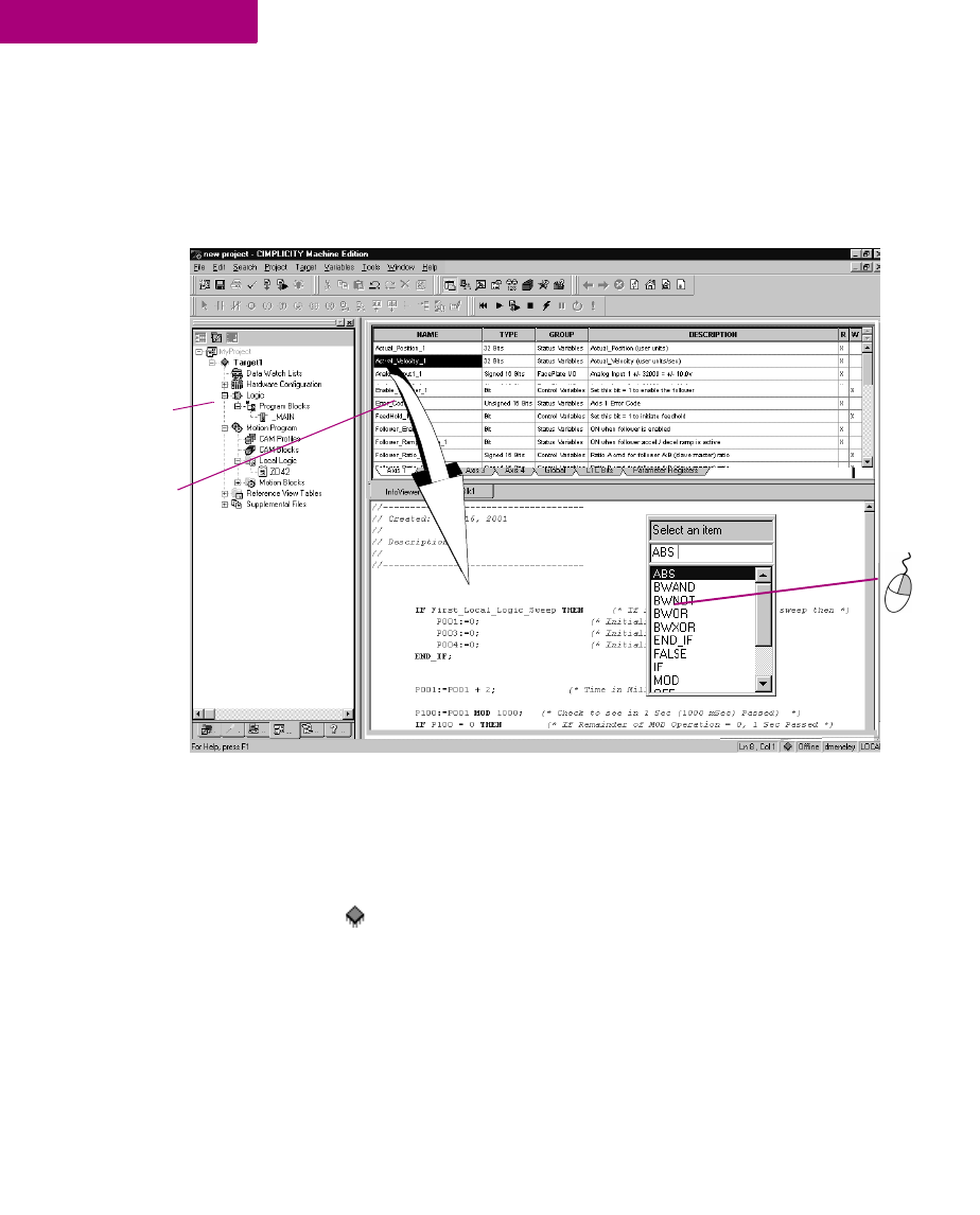
Motion Programming
Local Logic
96 CIMPLICITY Logic Developer - PLC Version 4.00 GFK-1918D
6
Working with Local Logic Editor
The Local Logic editor has its own distinctive syntax for constructing Local Logic
programs.
To insert a Local Logic command
1. In the Local Logic editor, right-click and choose Insert Keyword from the menu.
A smart list appears showing all available Local Logic commands.
2. Select the desired command in the smart list and press ENTER
The command is inserted.
Note: You can drag variables from the Local Logic Variable Table to the Local
Logic editor.
Drag and drop
variables from the
Local Logic
Variable table into
the Local Logic
editor.
Navigator shows
the organization of
your project.
Right-click to
choose
commands
from a list.
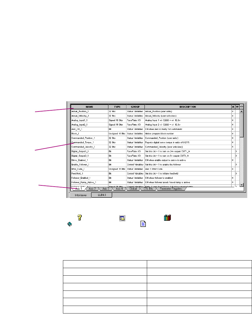
Motion Programming
Local Logic
GFK-1918D CIMPLICITY Logic Developer - PLC Version 4.00 97
Local Logic Variables
Local Logic is designed to complement a PLC’s logic and mathematical
capabilities. Solving small Local Logic and mathematical sets require a tight
synchronization with the controlled motion.
Logic Developer - PLC includes a table containing Local Logic variables, the Local
Logic Variable Table (LLVT), that you can drag into your logic programs. As
illustrated in the diagram below, the LLVT has several tabs that organize the
variables by category:
To view the LLVT
1. In the InfoViewer tab of the Navigator, expand the Logic Developer - PLC library then expand the
Local Logic Editor book and double-click Local Logic Variable Table.
The LLVT appears in the Infoviewer.
The variables or data in each tab are:
Axis 1 Variables specific to axis 1
Axis 2 Variables specific to axis 2
Axis 3 Variables specific to axis 3
Axis 4 Variables specific to axis 4
Global Global data such as module status code
CTL bits DSM general Control/Status bits
Parameter Registers DSM parameter data
Click a heading to
sort the table in
ascending order.
Click again to sort
descending.
Click a tab to view a
group of variables
Right-click a name
to copy it to the
clipboard.

Motion Programming
Local Logic
98 CIMPLICITY Logic Developer - PLC Version 4.00 GFK-1918D
6
The table has six columns:
To insert a Local Logic variable
1. In the Local Logic editor, right-click and choose Insert Variable.
A smart list appears prompting you to choose a Local Logic variable name.
2. Select a variable in the list and press ENTER.
The variable is inserted in your Local Logic.
Name Contains the variable name that is to be used within a
Local Logic program
Type The data type for this variable. For example, 32-bit
means that this variable is a 32-bit variable.
Group The group this variable is placed in. For example,
Faceplate I/O means that this variable refers to a point
on the module faceplate.
Description This column contains a textual description of the
variable. When the user hovers the mouse pointer over
the description, a tool tip displays the description.
R This column indicates if the variable can be read by a
Local Logic program.
W This column indicates if the variable can be written by a
Local Logic program.
Motion Programming
Local Logic
GFK-1918D CIMPLICITY Logic Developer - PLC Version 4.00 99
Local Logic Commands and Operators
Local Logic enables you to execute basic logic and mathematical functions on the
DSM module. Commands use upper case characters only and are case sensitive.
ABS TRUE -(minus) <= (less than or equal to)
BWAND FALSE / (divide) <> (not equal)
BWOR IF * (multiply)
BWXOR THEN :=(assign)
BWNOT END_IF >(greater than)
ON MOD < (less than)
OFF + plus >= (greater than or equal to)
Want to know more?
In the Help Index, choose “Local Logic: an Overview”.
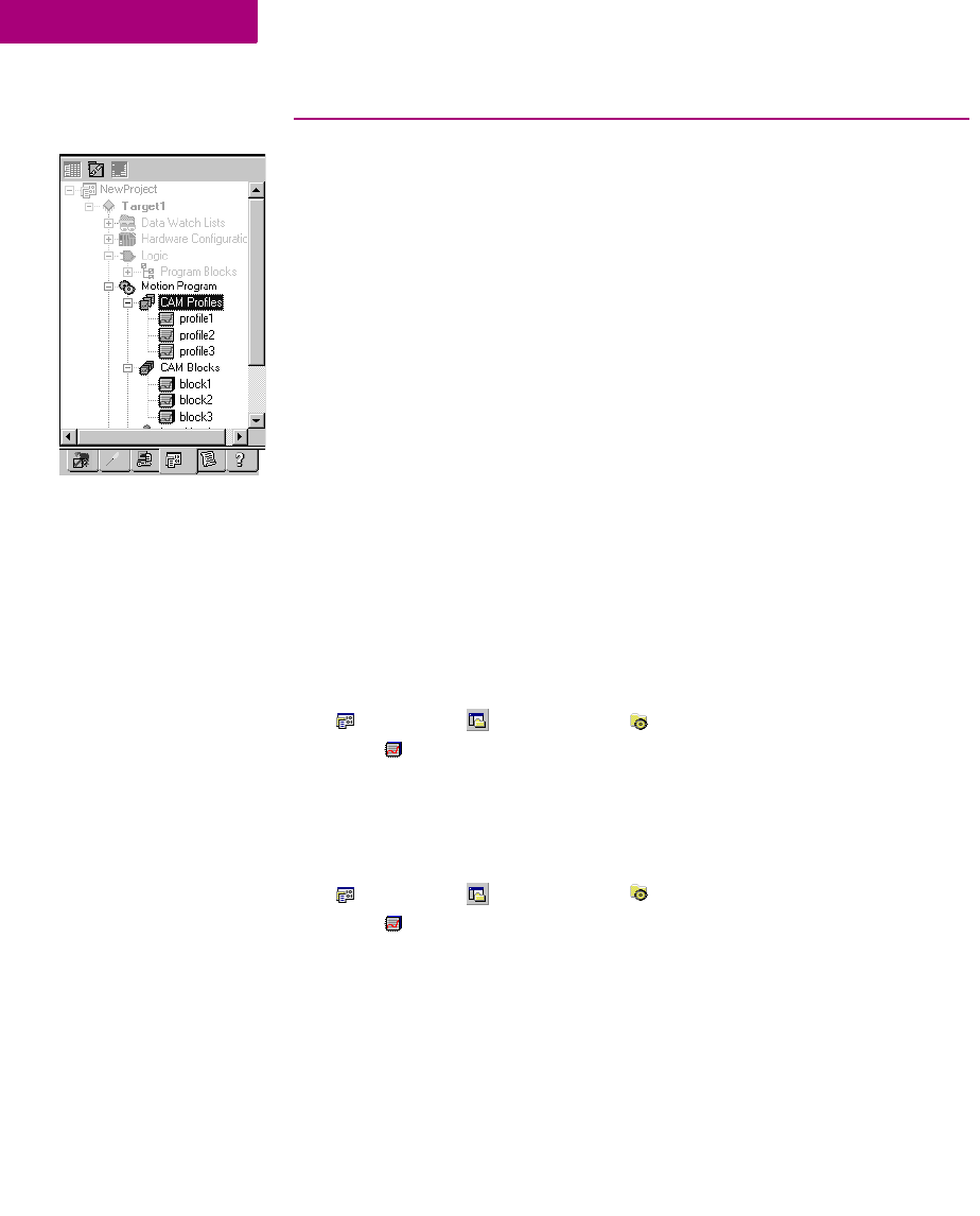
Motion Programming
CAM Editor
100 CIMPLICITY Logic Developer - PLC Version 4.00 GFK-1918D
6
CAM EDITOR
The CAM editor is an accessory for Logic Developer - PLC motion programming
that provides a means to create, edit, and manage electronic CAM profiles. Each
CAM profile is a curve that specifies the response of a slave servo to a master
position index. CAM profiles are referenced by name in the associated motion
program and grouped into CAM blocks. Each block is intended for download to a
specific motion module by means of a PLC controller. The hardware components
are specified in the HWC for the associated project.
CAM profiles are user-defined in a library and then grouped into blocks by aliasing
them. This allows you to reuse CAM profiles by including them in multiple CAM
blocks.
To create a CAM block
1. In the Project tab of the Navigator, expand the Motion Program folder.
2. Right-click the CAM blocks folder and choose New.
A new CAM block with a default name is created.
3. Rename the block as desired.
To import CAM blocks
1. In the Project tab of the Navigator, expand the Motion Program folder.
2. Right-click the CAM blocks folder and choose Import from File.
The Open dialog box appears.
3. Browse to the CAM block you want to import (.csv or .txt file).
4. Click Open.
The imported block appears in your project.
Project Tab: Navigator
CAM Blocks
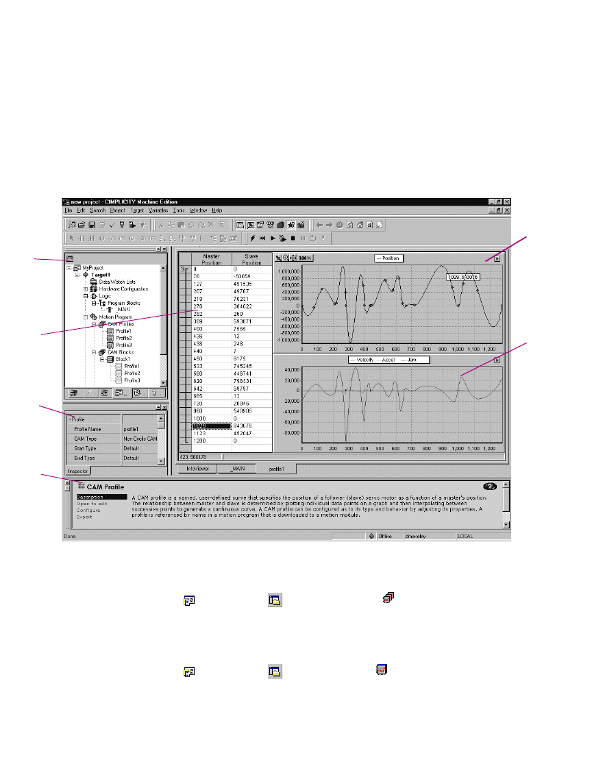
Motion Programming
CAM Editor
GFK-1918D CIMPLICITY Logic Developer - PLC Version 4.00 101
Working with the CAM Editor
You can adjust the curves of your CAM profile to suit the specific needs of your
project. With the CAM editor you create profiles by defining points on a
master/slave position curve. Groups of adjoining points are allocated to sectors.
Each sector is assigned a polynomial curve fit order (1,2,3) that specifies how the
curve will be interpolated between points.
To create a CAM profile
•In the Project tab of the Navigator, right-click the CAM Profiles folder and choose New.
A new CAM profile with a default name is added to your project.
To configure a CAM profile
1. In the Project tab of the Navigator, right-click a CAM profile and choose Properties.
The Inpector displays the properties of the CAM profile.
2. Adjust the properties of the CAM profile in the Inspector to specify its type and boundary conditions.
Curves of the
profile can be
adjusted and
edited
graphically.
Secondary
curves show
the velocity,
acceleration
and jerk of
the CAM
profile.
CAM profile
table allows
numeric editing
and curve order
grouping
The Companion
tracks your
moves and
provides
information on
what you click.
Navigator
displays CAM
profiles and
blocks.
Configure
profiles and
blocks in the
Inspector.
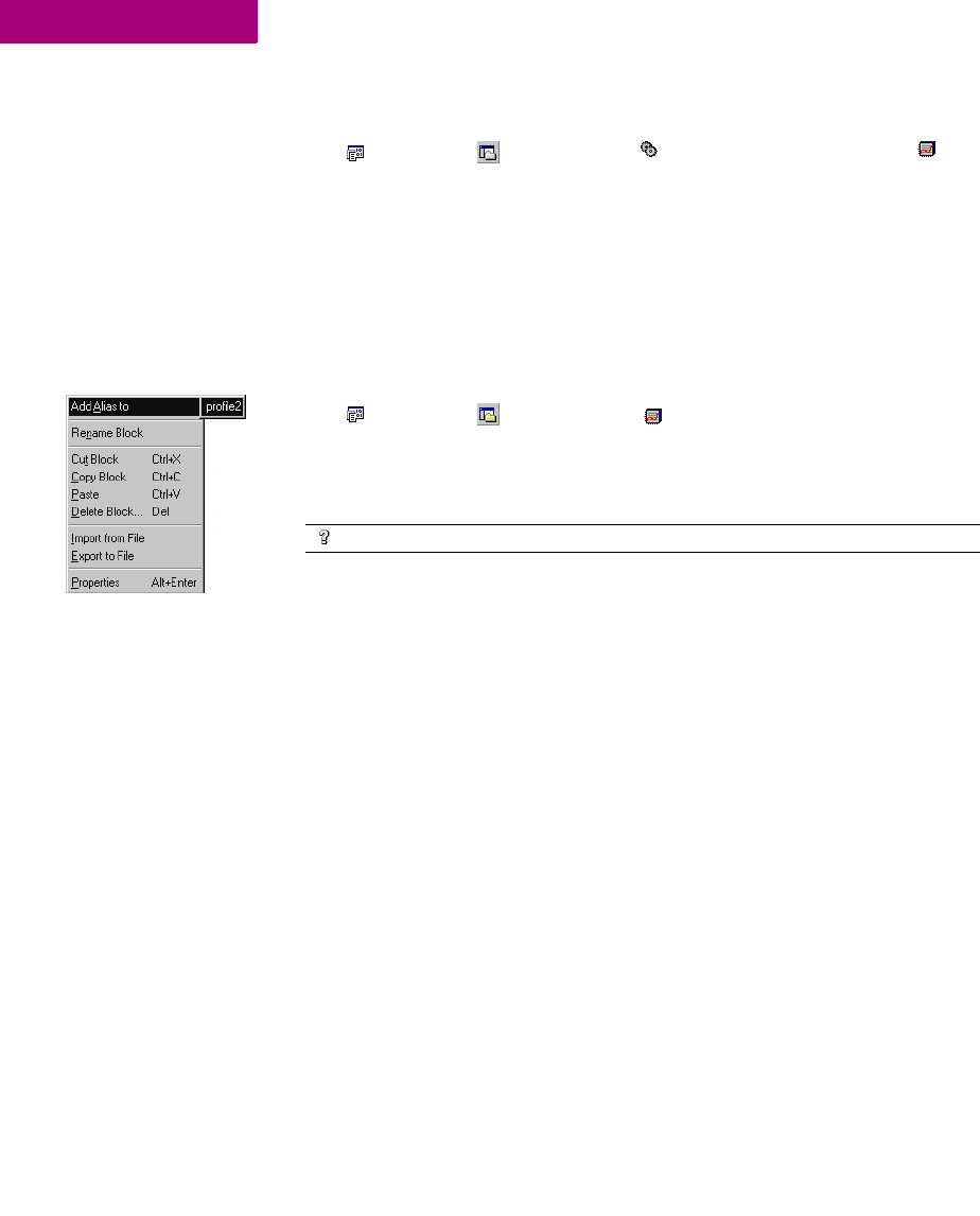
Motion Programming
CAM Editor
102 CIMPLICITY Logic Developer - PLC Version 4.00 GFK-1918D
6
To edit a CAM profile
1. In the Project tab of the Navigator, expand the Motion Program folder and double-click a CAM
profile.
A graphical representation of your profile appears in the profile editor and a
numeric representation appears in the profile table.
2. Insert and move points in the profile editor or table.
3. Group points into sectors in the profile table and assign curve fit order to each sector.
To add an alias to a CAM block
•In the Project tab of the Navigator, right-click a CAM block, point to Add Alias to, and then choose
a profile.
Note: Aliases correspond to CAM profiles within CAM blocks. In order to create
aliases for CAM blocks, you must have previously created CAM profiles.
Want to know more?
In the Help Index, choose “CAM”.

Index
GFK-1918D CIMPLICITY Logic Developer - PLC Version 4.00 103
Index
A
Access Control
Setting 65
Accumulators
Configuring 79
Adding
Carrier/Base to VersaMax
Remote I/O 60
DSM314 Motion Module 55
Ethernet Modules
(PACSystems™) 49
Genius Bus Controllers 53
Modules to a Carrier/Base 61
Adding Targets 24
Address and Length (LD)
Configuring 68
Address Use Report 40
Advanced Math Functions
IL 84
LD 75
Aliases 102
Analog Start Address 79
Arrays 16
Assigning
Operands to an
Instruction 80
Variables to Operands 70
B
Basic CPU Redundancy 50
Basic Instructions
IL 84
Bit Operations
IL 84
LD 75
Bit References 18
Blocks
_MAIN 63
C2, 63, 86
CAM 100, 102
IL 63
LD 63, 66
Local Logic 95
PLC Motion 92
Reports 40
Scheduling 64
BOOL Variables
Changing the State 82
Forcing the State 83
Removing the Force 83
Boolean Start Address 79
Build Tab 33, 35
C
C Block Report 40
C Blocks 2, 63, 86
Importing 86
Setting Parameters 87
C Programs 2, 63, 88
Setting Parameters 89
CAM Blocks 100, 102
Aliases 102
Creating 100
Importing 100
CAM Editor 2, 91, 100
CAM Profile Report 40
CAM Profiles
Configuring 101
Creating 101
Editing 102
Carrier/Base 61
Adding Modules 61
Adding to VersaMax Remote
I/O 60
Changing the State of BOOL
Variables 82
Choosing
CPUs 45
Power Supplies 45
CIMPLICITY Machine Edition 1,
2, 6, 9, 12, 32, 35
CIMPLICITY Motion 2, 12
CIMPLICITY View 2, 12
CimplicityControl 1, 12
Coils
LD 75
COM 25
COM ports 28
Communication
Configuring with non-
PACSystems™ RX7i 30
Configuring with
PACSystems™ RX7i 28
Ethernet 28
Serial Connection 28
Companion 15, 33
Companion Help
Using 20
Compound Structure
Variables 16
Configuring
Accumulators 79
Address and Length (LD) 67,
68
CAM Profiles 101
Communication with non-
PACSystems™ RX7i 30
Communication with
PACSystems™ RX7i 28
CPUs 32, 46
DSM314 55, 56

Index
104 CIMPLICITY Logic Developer - PLC Version 4.00 GFK-1918D
Ethernet Communication 28
Ethernet Daughterboard 48
Execution Scheduling 89
Hardware 27, 43
PACSystems™ RX7i 44
Redundant Systems 52
Remote I/O 1
Scheduling 64
Secondary HWC 54
Serial Communication 28
Targets 25
VersaMax Remote I/O 59
Contacts
LD 75
Context-Sensitive Help 15, 20
Control Functions
IL 84
LD 76
Conversion Functions
IL 84
LD 76
Conversion Reports 27
Converting Targets 26
Copying
Entire LD Blocks as text 71
Sections of LD Blocks as
text 71
Text into the LD Editor 71
Counters
IL 84
LD 76
CPE010 45
CPU
Choosing 45
Configuring 32, 46
CPU Redundancy
Setting Up Primary HWC 52
CPU Redundancy Over
Genius 50, 51
CPU364 31
CPU374 31
Creating
CAM Blocks 100
CAM Profiles 101
IL Blocks 79
Local Logic Blocks 95
Projects 12, 43
Reports 40
User-Defined Folders 64
User-Defined RVTs 39
Variables 17
Variables from Names 81
Variables from Reference
Addresses 81
CTL Bits (Local Logic) 95
Customizing the LD Editor 66
D
Data Move Functions
IL 85
LD 76
Data Table Functions
IL 85
LD 77
Data Values
Monitoring 82
Data Watch Tool 14
Default RVTs 38
Diagnostics 37
Documentation Address 25
Downloading IP Addresses
non-PACSystems™ 32
PACSystems™ RX7i 29, 30
Downloading to a Target 35
DSM314 55, 56, 91, 92, 95
Adding 55
Configuring 55, 56
Dual HWC 25, 53, 54
Duplicating IL Logic 81
E
Editing
CAM Blocks 101
CAM Profiles 102
IL Blocks 79
LD Blocks 67, 70
LD Logic 70
Local Logic Blocks 95
PLC Motion Blocks 92
Projects 12
Variables 16
Editing Online 72
Editors
CAM 2, 91, 100
IL 2, 79
LD 2, 66
Local Logic 2, 91, 96
Logic 63
PLC Motion 2, 91, 92
Ethernet 25, 28, 44, 48, 49
Adding Modules 49
Ethernet Adapter 28
Ethernet Daughterboard 44
Configuring 48
Executing Programs 37
Execution Scheduling
Configuring 89
Expansion Racks 43, 44, 47
F
Fan Kits
Adding to PACSystems™
RX7i 48
Catalog 48
Intelligent 43
Non-Intelligent 43
Fault Locating References 27
Fault Table Reports 37
Fault Tables 37
Feedback Zone 14, 33, 35, 40, 41
Finding text
Global Search 65
In one block 65
Folders
Importing 13
Forcing BOOL Variables 74, 83
Functions
IL 84
LD 75
fxClasses 15
G
GBC 54, 57

Index
GFK-1918D CIMPLICITY Logic Developer - PLC Version 4.00 105
Adding 53
GE Fanuc
PLC 1, 2, 24
Remote I/O 24
Series 90™-70 Genius
Remote I/O Scanner 23
VersaMax Ethernet 23
VersaMax Genius 23
VersaMax Profibus 23
Genius Bus Controller (GBC) 54,
57
Adding 53
Genius Devices 44
Genius Redundancy 50, 51
Global Search 65
Going Offline from a Target 34
Going Online to a Target 34, 72
H
Hardware
Configuring 27, 43
Hardware Configuration
(HWC) 2, 26, 43
Hardware Configuration
Report 40
Help
Companion 20
InfoViewer 20
Help Index 21
HWC 26, 43
Dual 54
Primary 50, 55
Secondary 50, 54, 55
Synchronizing 55
Hyperlinks 41
I
IL Block Comments
Inserting 81
IL BlockReport 40
IL Blocks 63
Creating 79
Editing 79
IL Code
Reformatting 81
IL Editor 2, 79
Offline 80
Online 82
IL Functions 84
Advanced Math 84
Basic Instructions 84
Bit Operations 84
Control 84
Conversion 84
Counters 84
Data Move 85
Data Table 85
Math 85
Program Flow 85
Relational 85
Timers 85
IL Inline Comments
Inserting 81
IL Instructions 84
Inserting 80
IL Logic 2, 79
Duplicating 81
Moving 81
Importing
C Blocks 86
CAM Blocks 100
Folders 13
Index 21
InfoViewer 15, 40
InfoViewer Help 20
Inserting
IL Block Comments 81
IL Inline Comments 81
IL Instructions 80
LD Instructions 68
Inspector 14
Installation 4
Instruction List (IL) 79
Instructions
IL 84
LD 75
Interacting with the PLC 33
Internet Explorer 15
IP Address 25, 32
Downloading to non-
PACSystems™ 32
Downloading to
PACSystems™ RX7i 29,
30
Setting for Lower-End Series
90™-30 32
Setting for PACSystems™
RX7i (Permanent) 30
Setting for PACSystems™
RX7i (Temporary) 29
Setting for Series 90™-30
CPU364 31
Setting for Series 90™-30
CPU374 31
Setting for Series 90™-70 30
L
Ladder Diagram Logic 2
LD Blocks 63, 66
Copying Entire as Text 71
Copying Sections as Text 71
Editing 67, 70
Printing 41
Reports 40
LD Editor 2, 66, 70
Copying Text into 71
Customizing 66
Offline 67
Online 72
LD Functions 75
Advanced Math 75
Bit Operations 75
Coils 75
Contacts 75
Control 76
Conversion 76
Counters 76
Data Move 76
Data Table 77
Math 77
Program Flow 78
Relational 78
Timers 78
LD Instructions 75

Index
106 CIMPLICITY Logic Developer - PLC Version 4.00 GFK-1918D
Inserting 68
LD Logic 2, 66, 70
LLVT 97
Local Logic 2, 91, 95
Local Logic Block Report 40
Local Logic Blocks
Creating 95
Editing 95
Local Logic Editor 2, 91, 96
Logic
IL 2, 79
LD 2, 66, 70
Local 2, 91
Logic Developer - PC 2, 12
Logic Developer - PLC 1, 2, 5, 6,
12, 23, 25, 33, 36, 43, 55, 63
Logic Developer - State 2, 12, 36
Logic Editors 63
Logic Printouts 40
Logicmaster 1, 12
M
Machine Edition 1, 2, 9, 12, 32, 35
Starting 10
Making Word-for-Word
Changes 73
Mapping Variables 17
Math Functions
IL 85
LD 77
Mnemonics 80
Modem 25
Module Catalog 30, 46, 47, 49,
60, 61
Monitoring Data Values 82
Motion 2, 12
Motion Programming 91
Motion Report 40
Moving IL Logic 81
N
Navigator 14, 16, 34, 38
Network Administrator 31
Network Interface Unit (NIU) 59
NIU 59
O
Offline 33
Going Offline from a
Target 34
IL Editor 80
LD Editor 67
Offline PLC Operations
Disabled 34
Enabled 33
Online 33
Going Online to a Target 34
IL Editor 82
LD Editor 72
Target PLC 72
Online Editing 72
Online Force Report 40
Opening a Project 13
Operands
Assigning to an
Instruction 80
Assigning Variables 70
Options Tab 34, 38
P
PACSystems™ RX7i 16, 23, 26,
28, 43, 66, 72, 73, 75
Adding Fan Kits 48
Configuring 44
Downloading IP
Addresses 29, 30
Setting Permanent IP
Addresses 30
Setting Temporary IP
Addresses 29
Parameter Data (Local Logic) 95
Parameter Editor 31, 46, 56
Parameters
C Blocks 87
C Programs 89
Permanent IP Address
Setting for PACSystems™
RX7i 30
PLC 1, 24
Family 25, 43
Interacting with 33
Motion Blocks 92
Motion Editor 2, 91, 92
Offline Operations 33, 34
Starting 37
Status 25
Stopping 37
Power Supply 59
Choosing 45
Primary HWC 50, 55
Setting Up for CPU
Redundancy 52
Printing
LD Blocks 41
Reports 41
Product Authorization 5
Program Flow Functions
IL 85
LD 78
Programs
C Programs 2, 63, 88
User Programs 88, 89
Projects
CIMPLICITY Machine
Edition 9
Creating 12, 43
Downloading 35
Editing 12
Executing 37, 82, 99
Importing Folders 13
Opening 13
Uploading 35
PSA100 45
Q
Quick Start 10
R
Racks 43, 59
Expansion 43, 44, 47
Replacing 47
Secondary 44, 47

Index
GFK-1918D CIMPLICITY Logic Developer - PLC Version 4.00 107
Redisplaying Reports 41
Redundancy 50
Basic CPU 50
Configuring Systems 52
CPU Over Genius 50, 51
Genius 50, 51
Wizards 52, 53
Reference Address 16, 39, 68
Reference View Tables
Default 38
User-Defined 38
Working with 40
Reference View Tables (RVT) 38
Reformatting IL Code 81
Relational Functions
IL 85
LD 78
Remote I/O 2, 24, 43, 60
Configuring 1
Remote I/O Scanner 57
Setting Up 58
Removing the Force from BOOL
Variables 83
Replacing
Racks 47
Text 65
Reports 40
Address Use 40
C Block 40
CAM Profile 40
Conversion 27
Creating 40
Fault Table 37
Hardware Configuration 40
IL Block 40
LD Blocks 40
Local Logic Block 40
Motion 40
Online Force 40
Printing 41
Redisplaying 41
Variables 40
Reports Tab 40, 41
Right-Click Menu
HWC 45
Target 33, 91
RMS 72
Run Mode 36
Run Mode Store (RMS) 72
Runtime Destination 23
Runtime Files 35
RVT 38
S
SBA Node 57
Scheduling
Blocks 64
Configuring 64
User Programs 89
Searching
Global Search 65
In one block 65
Secondary HWC 50, 55
Configuring 54
Secondary Racks 44, 47
Serial Communication 28
Series 90™ Micro 23, 73
Series 90™-30 23, 44, 55, 66, 73
Series 90™-70 23, 26, 43, 44, 50,
66, 73, 75, 88
Remote I/O Scanner 23
Series 90™-70 Genius Remote I/O
Scanner 23, 57
Setting Access Control 65
Setting IP Addresses
Lower-End Series 90™-30 32
PACSystems™ RX7i
(Permanent) 29
PACSystems™ RX7i
(Temporary) 29
Series 90™-30 CPU364 31
Series 90™-30 CPU374 31
Series 90™-70 30
Setting Parameters
C Blocks 87
C Programs 89
Setting Up
Primary HWC for CPU
Redundancy 52
Remote I/O Scanner 58
Slots 44, 45
SNP_ID 28
Starting a PLC 37
Starting Machine Edition 10
Status Bar 34
Stop Mode 36
Stopping a PLC 37
Sweep Time 25
Symbolic Variables 16, 17
Synchronizing
HWCs 55
System Requirements 3
T
Table of Contents 22
Target Properties 25
Targets 23, 63
Adding 24
Configuring 25
Converting 26
Downloading 35
Going Offline 34
Going Online 34, 72
Offline 33
Online 33
PACSystems™ RX7i 23
Remote I/O Scanner 57
Right-Click Menu 33, 91
Run Mode 36
Series 90™ Micro 23
Series 90™-30 23
Series 90™-70 23
Series 90™-70 Remote I/O
Scanner 23
Stop Mode 36
Uploading 36
Validating 33
VersaMax 23
VersaMax Ethernet 23
VersaMax Genius 23
VersaMax Nano/ Micro 23
VersaMax Profibus 23
Writing Changes 74, 83
Technical Support 7
Templates 12, 24, 59

Index
108 CIMPLICITY Logic Developer - PLC Version 4.00 GFK-1918D
Temporary IP Address
Setting for PACSystems™
RX7i 29
Timers
IL 85
LD 78
Toolchest 15
Tools 14
U
Uploading from a Target 36
URL 25
User Programs 88, 89
Scheduling 89
User-Defined Folders
Creating 64
User-Defined RVTs 38
Creating 39
Using 21, 22
Using Help
Companion Help 20
Help Index 21
InfoVeiwer Help 20
Table of Contents 22
Using Templates to Create
Projects 12
V
Validating Targets 33
Variables 16, 27
Compound Structure 16
Creating 17
Creating from Names 81
Creating from Reference
Addresses 81
Editing 16
Forcing 74
Mapping 17
Symbolic 16, 17
Turning On or Off 74
Variables Report 40
VersaMax 23, 66, 73
Adding Carrier/Base to
Remote I/O 60
Configuring Remote I/O 59
Ethernet 23
Genius 23
Nano/ Micro 23, 73
Profibus 23
Remote I/O 59
VersaPro 1, 12
View 2, 12
Viewing Fault Table Reports 37
W
Windows Explorer 14
Word-for-Word Changes 34, 72
Making 73
Working with Reference View
Tables 40
Writing Changes to a Target 74
Writing Changes to a Target
PLC 83
