GE JB255DJ2BB User Manual ELECTRIC RANGE Manuals And Guides 1402440L
User Manual: GE JB255DJ2BB JB255DJ2BB GE ELECTRIC RANGE - Manuals and Guides View the owners manual for your GE ELECTRIC RANGE #JB255DJ2BB. Home:Kitchen Appliance Parts:GE Parts:GE ELECTRIC RANGE Manual
Open the PDF directly: View PDF ![]() .
.
Page Count: 2
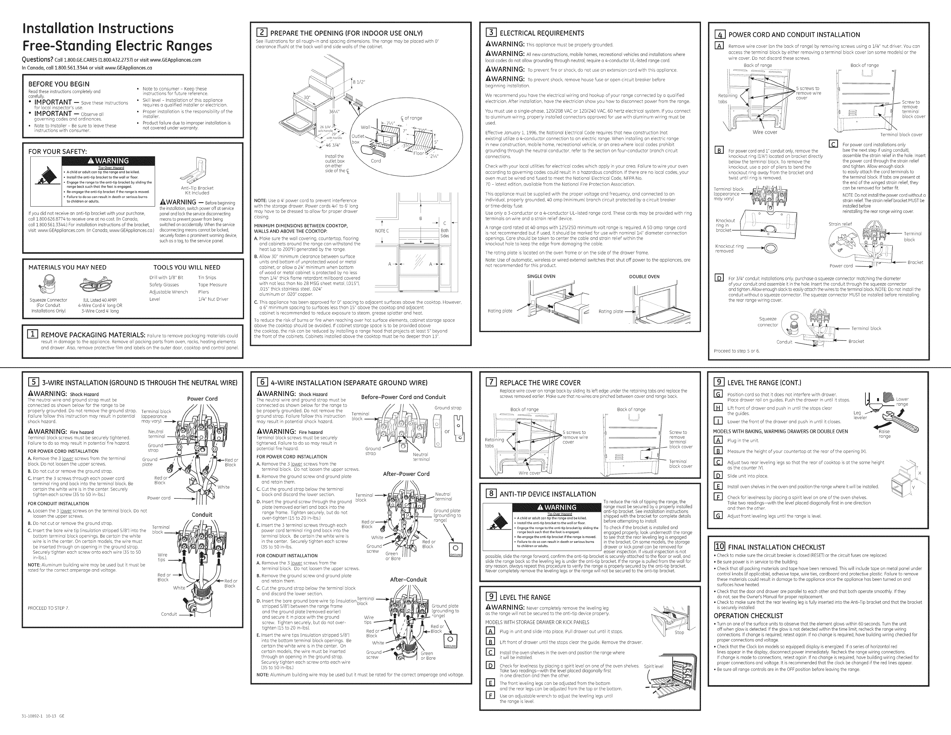
Installation Instructions
Free-Standing Electric Ranges
Questions? Call 1.800.GE.CARES (1.800.432.2737) or visit www.GEAppliances.com
In Canada, call 1.800.561.3344 or visit www.GEAppliances.ca
BEFORE YOU BEGIN
Readthese instructions completely and
carefully.
" IM PORTANT -- Savethese instructions
for local inspector's use.
" IMPORTANT -- Observeall
governingcodes and ordinances,
, Note toInstaller- Be sureto leavethese
instructionswithconsumer.
, Note to consumer - Keep these
instructions for future reference.
, Skill level - Installation of this appliance
requires a qualified installer or electrician.
. Proper installation is the responsibility of the
installer.
. Product failure due to improper installation is
not covered under warranty.
FOR YOUR SAFETY:
! A D
TLo-Over Hazard
• A child or adult cen tip the range and be killed.
•Install the enti-tip bracket to the wall or floor.
•Engage the range to the enti-tip bracket by sliding the
range back such that the foot is engaged.
•Re-engage the anti-tip bracket if the range is moved.
•Failure to do so can result in death or serious burns
to children or adults.
If you did not receive an anti-tip bracket with your purchase,
call !.800.626.8774 to receive one at no cost. (In Canada,
call :!.800.561.3344.) For installation instructions of the bracket,
visit: www.GEAppliances.com (InCanada, www.GEAppliances.ca.)
Anti-Tip Bracket
Kit Included
AWARNING -- Beforebeginning
the installation,switch power off at service
paneland lockthe servicedisconnecting
meansto preventpowerfrombeing
switchedon accidentally.Whenthe service
disconnectingmeanscannot be locked,
securelyfastena prominentwarning device,
such asa tag,to the service panel.
MATERIALS YOU MAY NEED
@
Squeeze Connector (ULListed40 AMP)
(For Conduit 4-Wire Cord 4' long OR
Installations Only) 3-Wire Cord 4' long
TOOLS YOU WILL NEED
Drill with 1/8" Bit Tin Snips
Safety Glasses Tape Measure
Adjustable Wrench Pliers
Level 1/4" Nut Driver
r_ REMOVE PACKAGI NG MATERIALS: Failure to remove packaging materials could
result in damage to the appliance. Remove all packing parts from oven, racks, heating elements
and drawer. Also, remove protective film and labels on the outer door, cooktop and control panel.
PREPARE THE OPENING (FOR INDOOR USE ONLY)
See illustrations for all rough-in and spacing dimensions. The range may be placed with 0"
clearance (flush) at the back wall and side walls of the cabinet.
1/2"
361/4"
\_ 46 3/4"
Installthe
outlet box
on either
side of the
Cord
CL of range
NOTE: Use a 4' power cord to prevent interference
with the storage drawer. Power cords 4_' to 6' long
may have to be dressed to allow for proper drawer
closing.
MINIMUM DIMENSIONS BETWEEN COOKTOP,
WALLS AND ABOVETHE COOKTOP:
A. Make sure the wall covering, countertop, flooring
and cabinets around the range can withstand the
heat (up to 200°F) generated by the range.
B. Allow 30" minimum clearance between surface
units and bottom of unprotected wood or metal
cabinet, or allow a 24" minimum when bottom
of wood or metal cabinet is protected by no less
than 1/4" thick flame retardant millboard covered
with not less than No 28 MSGsheet metal, (.015"),
.015" thick stainless steel, .024"
aluminum or .020" copper.
NOTEC
BC
Both
Sides
i
i
i
i
C. This appliance has been approved for 0" spacing to adjacent surfaces above the cooktop. However,
a 6" minimum spacing to surfaces less than 15" above the cooktop and adjacent
cabinet is recommended to reduce exposure to steam, grease splatter and heat.
To reduce the risk of burns or fire when reaching over hot surface elements, cabinet storage space
above the cooktop should be avoided. If cabinet storage space is to be provided above
the cooktop, the risk can be reduced by installing a range hood that projects at least 5" beyond
the front of the cabinets. Cabinets installed above the cooktop must be no deeper than 13".
ELECTRICAL REQUIREMENTS
AWARNING: This appliance must be properly grounded.
_J_WARNI NG: All new constructions, mobile homes, recreational vehicles and installations where
local codes do not allow grounding through neutral, require a 4-conductor UL-listed range cord.
_,WARN ING: To prevent fire or shock, do not use an extension cord with this appliance.
_WARN] NG: To prevent shock, remove house fuse or open circuit breaker before
beginning installation.
We recommend you have the electrical wiring and hookup of your range connected by a qualified
electrician. After installation, have the electrician show you how to disconnect power from the range.
You must use a single-phase, 120/208 VAC or 120/240 VAC, 60 hertz electrical system. If you connect
to aluminum wiring, properly installed connectors approved for use with aluminum wiring must be
used.
Effective January 1, 1996, the National Electrical Code requires that new construction (not
existing) utilize a 4-conductor connection to an electric range. When installing an electric range
in new construction, mobile home, recreational vehicle, or an area where local codes prohibit
grounding through the neutral conductor, refer to the section on four-conductor branch circuit
connections.
Check with your local utilities for electrical codes which apply in your area. Failure to wire your oven
according to governing codes could result in a hazardous condition. If there are no local codes, your
oven must be wired and fused to meet the National Electrical Code, NFPA No.
70 - latest edition, available from the National Fire Protection Association.
This appliance must be supplied with the proper voltage and frequency, and connected to an
individual, properly grounded, 40 amp (minimum) branch circuit protected by a circuit breaker
or time-delay fuse.
Use only a 3-conductor or a 4-conductor UL-listed range cord. These cords may be provided with ring
terminals on wire and a strain relief device.
A range cord rated at 40 amps with 125/250 minimum volt range is required. A 50 amp range cord
is not recommended but if used, it should be marked for use with nominal 1_" diameter connection
openings. Care should be taken to center the cable and strain relief within the
knockout hole to keep the edge from damaging the cable.
The rating plate is located on the oven frame or on the side of the drawer frame.
Note: Use of automatic, wireless or wired external switches that shut olt power to the appliances, are
not recommended for this product.
SINGLE OVEN DOUBLE OVEN
Rating plate Rating
POWER CORD AND CONDUIT INSTALLATION
rA1 Remove wire cover (on the back of range) by removing screws using a 1/4" nut driver. You can
access the terminal block by either removing a terminal block cover (on some models) or the
wire cover. Do not discard these screws.
Back of range Back of range
li li
Wire cover
5 screws to
cover
For power cord and 1" conduit only, remove the
knockout ring (1_")located on bracket directly
below the terminal block. To remove the
knockout, use a pair of pliers to bend the
knockout ring away from the bracket and
twist until ring is removed.
[] E1
Terminal block ff,-,_--_[_-:_
(appearance "'"-'_,,_ @(_>(jl_r!_/[,_p/H
ring in I / '_ _ . /II
bracket i'
Knockout ring ___
removed
i
Screw to
remove
I terminal
block cover
Terminal blockcover
For power cord installations only
(seethe next step if using conduit),
assemble the strain relief in the hole. Insert
the power cord through the strain relief
and tighten. Allow enough slack
to easily attach the cord terminals to
the terminal block. If tabs are present at
the end of the winged strain relief, they
can be removed for better fit.
NOTE:Do not install the power cord without a
strain relief.Thestrain relief bracketMUSTbe
installed before
reinstallingthe rear range wiring cover.
El For 3/4" conduit installations only, purchase a squeeze connector matching the diameter
of your conduit and assemble it in the hole. Insert the conduit through the squeeze connector
and tighten. Allow enough slack to easily attach the wires to the terminal block. NOTE:Do not install the
conduit without a squeeze connector. The squeeze connector MUSTbe installed before reinstalling
the rear range wiring cover.
Squeeze
CONNeCtor Terminal block
Conduit _ ::_7 Bracket
Proceed to step 5 or 6.
3-WIRE INSTALLATION (GROUND IS THROUGH THE NEUTRAL WIRE)
AWARNING: Shock Hazard
The neutral wire and ground strap must be
connected as shown below for the range to be
properly grounded. Do not remove the ground strap. Terminal block
Failure follow this instruction may result in potential
shock hazard.
AWARNING: Fire hazard
Terminal block screws must be securely tightened.
Failure to do so may result in potential fire hazard.
FOR POWER CORD INSTALLATION
A. Remove the 3 lower screws from the terminal
block. Do not loosen the upper screws.
B. Do not cut or remove the ground strap.
C. Insert the 3 screws through each power cord
terminal ring and back into the terminal block. Be
certain the white wire is in the center. Securely
tighten each screw (35 to 50 in-lbs.)
(appearance
may vary)
Neutral
terminal
strap
Ground
plate
Red c
Black
FOR CONDUIT INSTALLATION
A. Loosen the 3 lower screws on the terminal block. Do not
loosen the upper screws.
B. Do not cut or remove the ground strap.
C. Insert the bare wire tip (insulation stripped 5/8") into the
bottom terminal block openings. Be certain the white
wire is in the center. On certain models, the wire must
be inserted through an opening in the ground strap.
Securely tighten each screw onto each wire (35 to 50
in-lbs.).
NOTE: Aluminum building wire may be used but it must be
rated for the correct amperage and voltage.
PROCEED TO STEP 7.
Power Cord
or
Black
Power cord
White
Terminal
block
Conduit
Wire
tips _
Red or _ \
Black Wh't_
Conduit ._
or
Black
31-i0892-i10-13 GE
4-WIRE INSTALLATION (SEPARATE GROUND WIRE)
AWARNING: Shock Hazard
The neutral wire and ground strap must be
connected as shown below for the range to
be properly grounded. Do not remove the
ground strap. Failure follow this instruction
may result in potential shock hazard.
AWARN IN G: Fire hazard
Terminal block screws must be securely
tightened. Failure to do so may result in
potential fire hazard.
FOR POWER CORD INSTALLATION
Before-Power Cord and Conduit
Terminal
block
or
strap Neutral
terminal
A. Remove the 3 lower screws from the
terminal block. Do not loosen the upper screws.
B. Remove the ground screw and ground plate After-Power Cord
and retain them.
C. Cut the ground strap below the terminal __._ /'/__/__
block and discard the lower section. Terminal
D. Insert the ground screw through the ground block /_91
plate (removed earlier) and back into the
range frame. Tighten securely, but do not
over-tighten (15 to 20 in-lbs.) Red or----_/_
E. Insert the 3 terminal screws through each Black ._\_
power cord terminal ring and back into the
White
Ground _
screw Green
or Bare
After-Conduit
terminal block. Be certain the white wire is
in the center. Securely tighten each screw
(35 to 50 in-lbs.
FOR CONDUIT INSTALLATION
A. Remove the 3 lower screws from the
terminal block. Do not loosen the upper screws.
B. Remove the ground screw and ground plate
and retain them.
C. Cut the ground strap below the terminal block
and discard the lower section.
Terminal
D. Insert the bare ground bare wire tip (insulationbloc k
stripped 5/8") between the range frame
and the ground plate (removed earlier)
and secure it in place with the ground Wire
screw. Tighten securely, but do not over- tips
tighten (15 to 20 in-lbs). Red or
E. Insert the wire tips (insulation stripped 5/8") Black
into the bottom terminal block openings. Be White
certain the white wire is in the center. On
certain models, the wire must be inserted
through an opening in the ground strap, screw
Securely tighten each screw onto each wire
(35 to 50 in-lbs.)
Neutral
Ground plate
(grounding to
range)
Red or '_
Black
Ground plate
(grounding to
range)
Red or_
Green
or Bare
NOTE: Aluminum building wire may be used but it must be rated for the correct amperage and voltage.
L_ REPLACE THE WIRE COVER
Replace wire cover on range back by sliding its left edge under the retaining tabs and replace the
screws removed earlier. Make sure that no wires are pinched between cover and range back.
Back arrange Back ofrange
_5 screws to
remove wire
cover
'ii
Screw to
remove
terminal
block cover
Terminal
block cover
[_ ANTI-TIP DEVICE INSTALLATION
Ti -Over Hazard
• A child or adult can tip the range and be killed.
• Install the anti-tip bracket to the wall or floor.
• Engage the range to the anti-tip bracket by sliding the
range back such that the foot is engaged.
• Re-engage the anti-tip bracket if the range is moved.
• Failure to do so can result in death or serious burns
to children or adults.
To reduce the risk of tipping the range, the
range must be secured by a properly installed
anti-tip bracket. See installation instructions
shipped with the bracket for complete details
before attempting to install.
Tocheck if the bracket is installed and
engaged properly, look underneath the range
to see that the rear leveling leg is engaged
in the bracket. On some models, the storage
drawer or kick panel can be removed for
easier inspection. If visual inspection isnot
possible, slide the range forward, confirm the anti-tip bracket is securely attached to the floor or wall, and
slide the range back so the leveling leg isunder the anti-tip bracket. If the range is pulled from the wall for
any reason, always repeat this procedure to verify the range is properly secured by the anti-tip bracket.
Never completely remove the leveling legs or the range will not be secured to the anti-tip bracket.
LEVEL THE RANGE
AWARNI NG: Never completely remove the leveling leg
as the range will not be secured to the anti-tip device properly.
MODELS WITH STORAGEDRAWEROR KICK PANELS
B]
B]
E1
El
El
El
Plug in unit and slide into place. Pull drawer out until it stops.
Lift front of drawer until the stops clear the guide. Remove the drawer.
Install the oven shelves in the oven and position the range where
it will be installed. L ]'_
Check for levelness by placing a spirit level on one of the oven shelves. S
Take two readings-with the level placed diagonally first
in one direction and then the other.
The front leveling legs can be adjusted from the bottom
and the rear legs can be adjusted from the top or the bottom.
Use an adjustable wrench to adjust the leveling legs until
the range is level.
LEVEL THE RANGE (CONT.)
Position cord so that it does not interfere with drawer.
Place drawer rail on guides. Push the drawer in until it stops.
r_ Lift front of drawer and push in until the stops clear
the guides.
D Lower the front of the drawer and push in until it closes.
MODELS WITH BAKING, WARMING DRAWERS OR DOUBLE OVEN
r_ Plug in the unit.
Measure the height of your countertop at the rear of the opening (X).
El Adjust two rear leveling legs so that the rear of cooktop is at the same height
as the counter (Y).
Slide unit into place.
El Install oven shelves in the oven and position the range where it will be installed.
El Check for levelness by placing a spirit level on one of the oven shelves.
Take two readings-with the level placed diagonally first in one direction
and then the other.
rG1 Adjust front leveling legs until the range is level.
,e
range
iY
FINAL INSTALLATION CHECKLIST
Check to make sure the circuit breaker is closed (RESET)or the circuit fuses ore replaced.
Be sure power is in service to the building.
Check that all packing materials and tope hove been removed. This will include tape on metal panel under
control knobs {if applicable), adhesive tope, wire ties, cardboard and protective plastic. Failure to remove
these materials could result in damage to the appliance once the appliance has been turned on and
surfaces hove heated.
Check that the door and drawer are parallel to each other and that both operate smoothly. If they
do not, see the Owner's Hanual for proper replacement.
Check to make sure that the rear leveling leg is fully inserted into the Anti-Tip bracket and that the bracket
issecurely installed.
OPERATION CHECKLIST
Turn on one of the surface units to observe that the element glows within 60 seconds. Turn the unit
off when glow is detected. If the glow is not detected within the time limit, recheck the range wiring
connections. If change isrequired, retest again. If no change isrequired, have building wiring checked for
proper connections and voltage.
Check that the Clock (on models so equipped) display isenergized. If a series of horizontal red
lines appear in the display, disconnect power immediately. Recheckthe range wiring connections.
If change is made to connections, retest again. If no change is required, have building wiring checked for
proper connections and voltage. It is recommended that the clock be changed if the red lines appear.
Be sure all range controls are in the OFFposition before leaving the range.
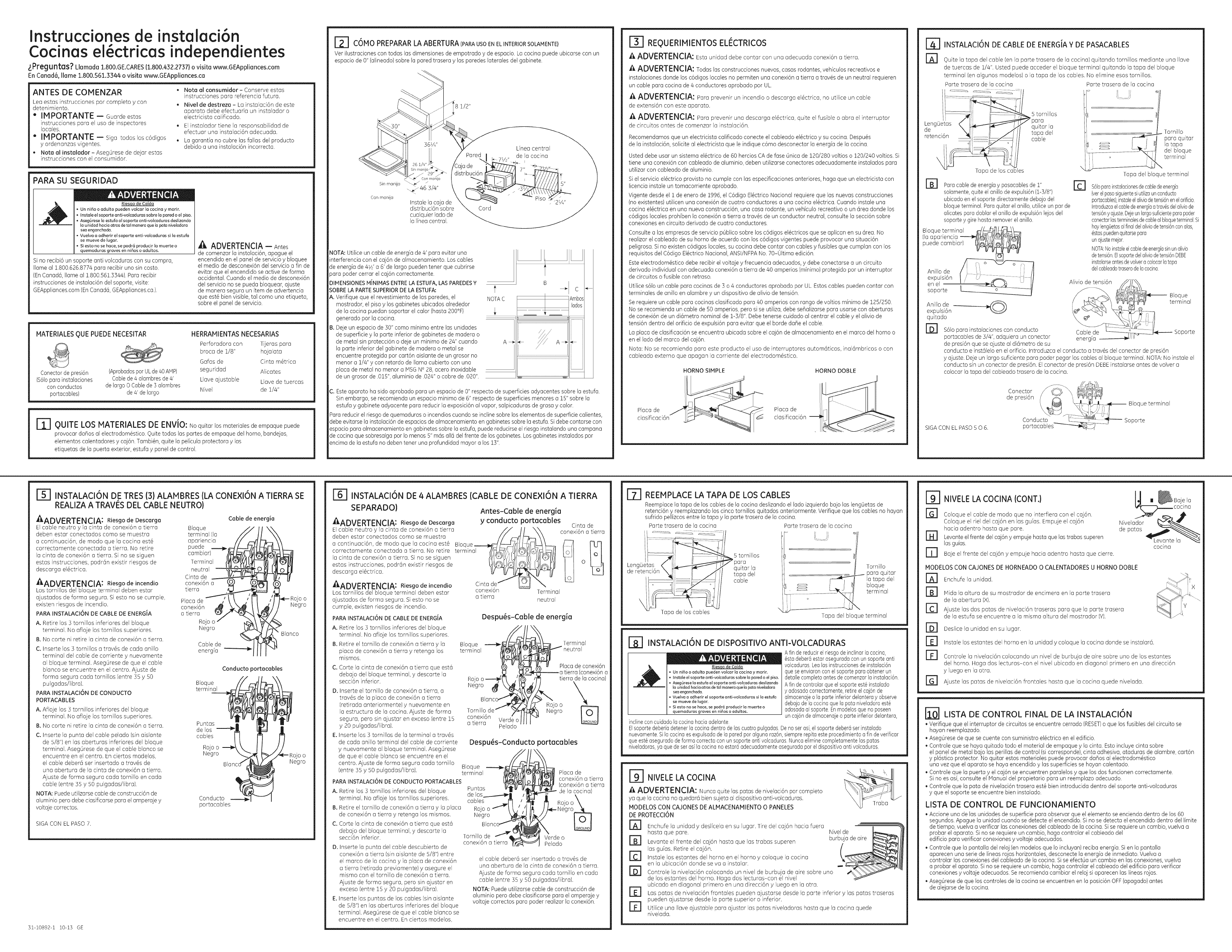
lnstrucciones de instalaci6n
Cocinas el6ctricas independientes
zPreguntas? Uarnada 1.800.GE.CARES (1.800.432.2737} o visita www.GEAppliances.com
En Canad6, Ilarne 1.800.561.3344 o visita www.GEAppliances.ca
ANTES DE COMENZAR
Lea estas instrucciones par completo ycon
detenimiento.
" IMPORTANTE -- Guarde estas
instrucdones pard el usa de inspectores
locales.
"IMPORTANTE -- Siga todos los c6digos
yordenanzas vigentes.
, Nota al instalador- AsegOrese de dejar estas
instrucciones con el consumidor.
, Nota al consumidor- Conserve estas
instrucdones pard referenda futura.
, Nivel de destreza - La instalaci6n de este
aparato debe efectuafla un instalador o
electricista caJificado.
, Elinstalador tiene Jaresponsabilidad de
efectuar una instalaci6n adecuada.
, La garant[a no cubre las fallas del producto
debido a una instalaci6n incorrecta.
PARA SU SEGURIDAD
Riesqo de Caida
• Un nifio o adulto pueden volcar la cocina y morir.
• Instale el soporte anti-volcaduras sabre la pared o el piso.
Asegdrese la estufa al soporte anti-volcaduras deslizando
la unidad hacia atras de tal manera que la pata niveladora
sea enganchada.
Vuelva a adherir el soporte anti-volcaduras si la estufa
se mueve de lugar.
Si esto no se hace, se podr6 producir la muerte o
quemaduras graves en nifios o adultos.
Si no recibi6 un soporte anti volcaduros con su compro,
Ilome al 1.800.626.8774 para recibir uno sin costa.
(En Canadd, Ilome ol 1.800.561.3344). Paro recibir
instrucciones de instoloci6n del soporte, visite:
GEApplionces.com (EnConadd, GEApplionces.co.).
,_ ADVERTENCIA -- Antes
de comenzor Io instoloci6n, apogue el
encendido en el panel de servicio ybloquee
el media de desconexi6n del servicio o fin de
evitar que el encendido se active de forma
occidental. Cuondo el media de desconexi6n
del servicio no se pueda bloquear, ajuste
de monero segura un item de advertencia
que est6 bien visible, tal coma uno etiqueto,
sabre el panel de servicio.
MATERIALESQUE PUEDE NECESITAR HERRAMIENTASNECESARIAS
_. Perforadora con Tijeras pard
broca de 1/8" hojalata
Galas de Cinta mdtrica
Conectorde presi6n (Aprobadospar ULde 40 AMP) seguridad Alicates
(Sdtoparo instalociones Cablede 4 atambresde 4' Llave ajustable Llave de tuercas
con conductos de largo O Cablede 3alambres
portacables) de 4' de largo Nivel de i/4"
r_ QUITE LOS HATERIALES DE ENVIO: Noquitar los materiabsdeempaquepuede
provocar dafios al electrodomdstico. Quite todas los partes de empaque del homo, bandejas,
elementos calentadores ycaj6n. Tambidn, quite la pelicula protectora ylos
etiquetas de la puerta exterior, estufa ypanel de control.
r=r_121C0MOPREPARARLA ABERTURA(PARAUSOENEL INTERIORSOLAMENTE}
Ver ilustraciones con todas los dimensiones de empotrado yde espacio. La cocina puede ubicarse con un
espacio de 0" (alineado) sabre la pared trasera ylos paredes laterales del gabinete.
:8 1/2"
Sin manila "_/ z
._. 463/4"
Con manila Instale la caja de
distfibuci6n sabre
cualquier 1adode
la lined central.
Lfnea central
Pared m de la cocina X
]de __7' _'1
Cord
NOTA: Utilice un cable de energ[a de 4' para evitar uno
interferencia con el caj6n de almacenamiento. Loscables
de energia de 4W a 6' de largo pueden tener que cubrirse
para poder cerrar el caj6n correctamente.
DIMENSIONES MINIMAS ENTRE LA ESTUFA,LASPAREDES Y
SOBRE LAPARTE SUPERIORDE LA ESTUFA:
A, Verifique que el revestimiento de los paredes, el
mostrador, el piso ylos gabinetes ubicados alrededor
de la cocina puedan soportar el color (hasta 200°F)
generado par la cocina.
B. Deje un espocio de 30" coma minima entre las unidades
de superficie yla porte inferior de gabinetes de madera o
de metal sin protecci6n o deje un minima de 24" cuando
la porte inferior del gabinete de madera o metal se
encuentre protegida par cart6n aislante de un grosor no
menor a 1/4" ycon retardo de llama cubierto con una
placa de metal no menor a jVlSGN° 28, acero inoxidable
de un grosor de .015",aluminio de .024"o cobre de .020".
NOTA C
A _
C, Esteaparoto ha sido aprobado para un espacio de 0" respecto de superficies adyacentes sabre la estufo.
Sinembargo, se recomienda un espacio minima de 6" respecto de superficies menores a 15" sabre la
estufa ygabinete adyacente pard reducir la exposici6n al vapor, salpicaduras de grasa ycolor.
Pard reducir el riesgo de quemaduras o incendios cuando se incline sabre los elementos de superficie calientes,
debe evitarse la instalaci6n de espacios de almacenamiento en gabinetes sabre la estufa. Si debe contarse con
espacio para almacenamiento en gabinetes sabre la estufa, puede reducirse el riesgo instalando una campana
de cocina que sobresalga par Io menos 5" m6s all6 del frente de los gabinetes. Losgabinetes instalados par
encima de la estufa no deben tener una profundidad mayor a los 13".
REQUERIMIENTOS EU]CTRICOS
A ADVERTENCIA: Esta unidad debe cantor con una adecuada conexi6n a tierra.
A ADVERTENCIA: Todas las construcciones nuevas, casas rodantes, veh[culos recreativos e
instalaciones donde los c6digos locales no permiten una conexi6n a tierra a trovds de un neutral requieren
un cable para cocina de 4 conductores oprobodo par UL.
A ADVERTENCIA: Para prevenir un incendio o descarga eldctrica, no utilice un cable
de extensi6n con este aparato.
A ADVERTENCIA: Para prevenir una descarga eldctrica, quite el fusible o abra el interruptor
de circuitos antes de comenzar la instalaci6n.
Recomendamos que un electricista calificado conecte el cobleodo el@trico ysu cocina. Despuds
de la instalaci6n, solicite al electricista que le indique c6mo desconectar la energia de la cocina.
Usted debe usar un sistema el_ctrico de 60 hercios CA de fase Onico de 120/280 voltios o 120/240 voltios. Si
tiene una conexi6n con cableodo de oluminio, deben utilizarse conectores odecuadomente instolodos para
utilizor con cableodo de aluminio.
Siel servicio el#ctrico provisto no cumple con las especificaciones onteriores, hago que un electricisto con
licencio instole un tomacorriente aprobado.
Vigente desde el i de enero de 1996, el C6digo El@trico Nacional requiere que los nuevas construcciones
(no existentes) utilicen una conexi6n de cuatro conductores a una cocina eldctrica. Cuando instale una
cocina eldctrica en una nueva construcci6n, una casa rodante, un vehiculo recreativo o un area donde los
c6digos locales prohiben la conexi6n a tierra a travds de un conductor neutral, consulte la secci6n sabre
conexiones en circuito derivado de cuatro conductores.
Consulte olas empresas de servicio p0blico sabre los c6digos eldctricos que se aplicon en su 6rea. No
realizar el cableado de su homo de acuerdo con losc6digos vigentes puede provocar una situaci6n
peligrosa. Sino existen c6digos locales, su cocina debe cantor con cables yfusibles que cumplan con los
requisitos del C6digo Eldctrico Nacional, ANSI/NFPANo. 70-01tima edici6n.
Esteelectrodomdstico debe recibir el voltaje yfrecuencia adecuados, ydebe conectarse aun circuito
derivado individual con adecuada conexi6n a tierra de 40 amperios (minima) protegido par un interruptor
de circuitos o fusible con retraso.
Utilice s61oun cable para cocinas de 3 o 4 conductores aprobado par UL Estoscables pueden contar con
terminales de anillo en alambre yun dispositivo de olivia de tensi6n.
Se requiere un cable pard cocinas clasificado pard 40 omperios con tango de voltios minima de 125/250.
No se recomienda un cable de 50 amperios, pero si se utiliza, debe seflalizarse pard usarse con aberturas
de conexi6n de un didmetro nominal de 1-3/8". Debe tenerse cuidado al centrar el cable yel olivia de
tensi6n dentro del orificio de expulsi6n pard evitar que el borde dafle el cable.
La placa de clasificaci6n se encuentro ubicada sabre el caj6n de almacenamiento en el marco del homo o
en el lado del marco del caj6n.
Nora: No se recomienda para este producto el usa de interruptores automdticos, inaJdmbricos o con
cableado externo qua apagan la corriente del electrodomdstico.
HORNO SIMPLE HORNO DOBLE
Placa de
dasificaci6n
Placa de
dasificaci6n
14.1 INSTALACION DE CABLEDE ENERGIAV DE PASACABLES
r_ Quite la tapa del cable (en la parte trasera de la cocina) quitando tornillos mediante una Ilave
de tuercas de 1/4". Usted puede acceder el bloque terminal quitando la tapa del bloque
terminal (en algunos modelos) ola tapa de los cables. No eFmine esos tornillos.
Parte trasera de la cocina Parte trasera de la cocina
5 tornillos
3ara
quitar la
tapa del
cable
\
Tapa de los cables
Para cable de energiaypasacablesde 1"
solamente,quite el anillo de expulsi6n (1-3/8")
ubicado en el soporte directamente debajo del
bloque terminal. Pard quitar el anillo,utilice un par de
alicates para doblar el anillo de expulsi6n lejosdel
soporte ygire hasta remover el anillo.
BIoque terminal
(la apariencia
puede cambiar
E1
Anillo de
expuisi6n
en el
soporte [
Tornillo
para quitar
la tapa
del bloque
terminal
Tapa del bloque terminal
S61oparainstalacionesdecabledeenergia
(verelpasosiguientesiutilizaunconducto
portacables),instaleelaliviodetensidnenelorificio
Introduzcaelcabledeenergiaatravdsdelaliviode
tensidnyajuste.Dejeunlargosufidenteparapoder
conectarlosterminalesdecableal bloqueterminalSi
haylengOetasalfinaldelaliviodetensi6nconalas,
6staspuedenquitarsepara
unajustemejor
NOTA:Noinstaleelcabledeenergiasinunolivia
detensidn.ElsoportedelaliviodetensidnDEBE
instalarseantesdevolvera colocarlatapa
delcableadotraserodelacocina
Anillo de
expulsi6n
quitado
r_ $61opara instalaciones con conducto
portacables de 3/4", adquiera un conector
de presi6n que se ajuste al di6metro de su
conducto e instdlelo en el orificio. Introduzca el conducto a travds del conector de presi6n
yajuste. Deje un largo suficiente para poder pegar los cables al bloque terminal. NOTA:No instale el
conducto sin un conector de presi6n. Elconector de presi6n DEBEinstalarse antes de volver a
colocar la tapa del cableado trasero de la codna.
SIGA CON EL PASO 50 6.
[_ INSTALACI6N DE TRES (3) ALAMBRES (LA CONE×I6N A TIERRA SE
REALIZA A TRAVES DEL CABLE NEUTRO)
A
_ADVERTENCIA: Riesgo de Descarga
El cable neutro yla cinta de conexi6n a tierra Bloque
deben estar conectados coma se muestra terminal fla
a continuaci6n, de modo que la cocina est# apariencia
correctamente conectada a tierra. No retire puede
la cinta de conexi6n a tierra. 8i no se siguen cambiar)
estas instrucciones, podrdn existir riesgos de Terminal
descarga eldctrica, neutral
Cinta de
conexi6n a
tierra
A
_ADVERTENCIA: Riesgo de incendio
Los tornillos del bloque terminal deben estar
ajustados de forma segura. Si esto no se cumple,
existen riesgos de incendio.
PARA INSTALACION DE CABLE DE ENERGJA
A. Retire 1as3 tornillos inferiores del bloque
terminal. No afloje los tornillos superiores.
B. No carte ni retire la cinta de conexi6n a tierra.
C. Inserte los 3 tornillos a travds de cada anillo
terminal del cable de corriente ynuevamente
al bloque terminal. Aseg0rese de que el cable
blanco se encuentre en el centro. Ajuste de
forma segura cada tornillos (entre 35 y50
pulgadas/libra).
PARA INSTALACI6N DE CONDUCTO
PORTACABLES
A. Afloje los 3 tornillos inferiores del bloque
terminal. No afloje los tornillos superiores.
B. No carte ni retire la cinta de conexi6n a tierra.
C. Inserte ]a punta del cable pelado (sin aislante
de 5/8") en las aberturas inferiores del bloque
terminal. AsegOrese de que el cable blanco se
encuentre en el centro. En ciertos modelos,
el cable deber6 ser insertado a travds de
una abertura de la cinta de conexi6n a tierra.
Ajuste de forma segura cada tornillo en cada
cable (entre 35 y 50 pulgadas/libra).
NOTA: Puede utilizarse cable de construcd6n de
aluminio pero debe dasificarse para el amperaje y
voltaje correctos.
Placa de
conexi6n
a tierra
Ro]o o
Negro
Cable de
energia
Cable de energia
o
Negro
Blanco
Conducto portacables
BIoque //_ MX\
termi
Puntas _ 1.1_1 m -
de los --'-"_ _ J
Rojoo-- \ I I //
Negro \-_ [_/'/z'_-_ Rojo o
.Bland Negro
Conducto _1 -_ I
portacables
SIGA CON EL PASO 7.
31-i0892-i i0-13 GE
| INSTALACI6N DE 4 ALAMBRES (CABLE DE CONEXI6N A TIERRA
SEPARADO} Antes-Cable de energia
AADVERTENCIA: Riesgo de Descarga y conducto portacables Cinta de
Elcableneutroylacintadeconexi6natierra _.__L_X_ conexi6natierra
deben estar conectados coma se muestra
a continuaci6n, de modo que la cocina est6 Bloque _
correctamente conectada a tierra. No retire terminal __
la cinta de conexi6n a tierra. Si no se siguen
estas instrucciones, podr(_n existir riesgos de O
descarga el6ctrica.
Cinta de _ _ "X
conexi6n Terminal
a tierra neutral
AADVERTENCIA: Riesgo de incendio
Los tornillos del bloque terminal deben estar
ajustados de forma segura. Siesto no se
cumple, existen riesgos de incendio.
PARA INSTALACI6N DE CABLE DE ENERGJA
A. Retire 1as3 tornillos inferiores del bloque
terminal. No afloje los tornillos superiores.
B. Retire el tornillo de conexi6n a tierra y la
placa de conexi6n a tierra yretenga los
mismos.
C. Carte la cinta de conexi6n a tierra que estd
deba]o del bloque terminal, y descarte Ja
secci6n inferior.
Despuds-Cable de energia
D. Inserte el tornillo de conexi6n a tierra, a
travds de la placa de conexi6n a tierra
(retirada anteriormente) y nuevamente en
la estructura de la cocina. Ajuste de forma
segura, pero sin ajustar en exceso (entre 15
y20 pulgadas/libra).
E, Inserte los 3 tornillos de la terminal a travds
de cada anillo terminal del cable de corriente
ynuevamente albloqueterminak Aseg0rese //ll
de qua el cable blanco se encuentre en el
centro. Ajuste de forma segura cada tornillo BIoque
(entre 35 ySOpuigadasllibra), terminal (_t_I_-
PARA INSTALAa6N DE CONDUCTO PORTACABLES Puntas _ _.t_
A. Retire los 3 tornillos inferiores del bloque de Ios......-.--_| /_#
terminal. No afloje los tornillos superiores, cables i_1 /
B. Retire el tornillo de conexi6n a tierra y la placa Rojo o "14_ / ,/ /Ill
de conexi6n a tierra y retenga los mismos. Negro _ /!_]
C. Carte la cinta de conexi6n a tierra que est6 Blanccr_'_f_._
debajo del bloque terminal, ydescarte la __
secci6n inferior. TornillOconexi6ndeatierra'/_'_
D. Inserte la punta de1cable descubierto de
conexi6n a tierra (sin aislante de 5/8'1 entre
el marco de la cocina yla placa de conexi6n
a tierra (retirada previamente) y asegure el
mismo con el tornillo de conexi6n a tierra.
Ajuste de forma segura, pero sin ajustar en
exceso (entre 15 y20 pulgadas/libra).
E, Inserte las puntas de los cables (sin aislante
de 5/8") en los aberturas inferiores del bloque
terminal. Aseg@resede que el cable blanco se
encuentre en el centro. En ciertos modelos,
Terminal
Placa de conexi6n
[conexi6n a
tierra de la cocino)
Rojo o _
Negro
Despuds-Conducto portacables
,,)
conexi6n a tierra
(conexi6n a tierra
_ Je la cocina
i _) Rojoo X
_,_- Negro_
Verde o
Pelado
el cable deber6 ser insertado a travds de
una abertura de la cinta de conexi6n a tierra.
Ajuste de forma segura cada tornillo en cada
cable (entre 35 y50 pulgadas/libra).
NOTA: Puede utilizarse cable de construcci6n de
aluminio pero debe clasificarse pard el amperaje y
voltaje correctos pard poder realizar la conexi6n.
r_ REEMPLACE LA TAPA DE LOS CABLES
Reemplace la tapa de los cables de la cocina deslizando el lado izquierdo bajo las lengLietas de
retenci6n yreemplazando los cinco tornillos quitados anteriormente. Verifique que los cables no haydn
sufrido pellizcos entre la tapa yla parte trasera de la cocina.
Parte trasera de la cocina Parte trasera de la cocina
_5 tornillos
pard ................................................................
quitar la
tapa del
cable
Tornillo
pard quitar
la tapa del
bloque
terminal
\
Tapa de los cables Tapa del _,q_o_ueterminal
E_ INSTALACI6N DE DISPOSITIVO ANTI-VOLCADURAS
Riesqo de Calda
• Un ni_o o adulto pueden volcar la cocina y morir.
• Instale el soporte anti-volcaduras sabre la pared o el piso.
• Aseg_rese la estufa al soporte anti-volcaduras deslizando
la unidad hacia atras detal manera que la pata niveladora
sea enganchada.
• Vuelva a adherir el soporte anti-volcaduras si la estufa
se mueve de lugar.
•Si esto no se hace, se podr6 producir la muerte o
quemaduras graves en niBos o adultos.
inclineconcuidadoIo cocinahacia adelante
A fin de reducirelriesgo de indinarla cocina,
6stodeber6estar aseguradacon un soporteanti
volcaduros Lealos instruccionesde instolacidn
qua seenvioronconel soporteporoobtenerun
detollecompbto antes de comenzorla instoladdn
A fin de controlarqueel soporteest@instolado
y adosodocorrectamente,retire elcaj6n de
olmocenojeola parte inferiordelonteroy observe
debajo de lacocina que Io pata niveladoraest@
odosadaol soporte Enmodelosque no poseen
un cajdn de olmocenojeo porte inferiordelantera,
Elsoportedeberiodetenerla cocinadentrode lascuatropulgados De no serosf,el soportedeber6serinstalodo
nuevamenteSi Io cocinaesexpulsadade Io paredpar olguna rozdn,siemprerepitaeste procedimientoa fin de verificar
queest@aseguradode forma correctaconun soporteantivolcaduros Nuncaeliminecompletamentelas potas
nivelodoras,ya quede ser asi la cocinanoestara adecuadamenteosegurodopar eldispositivoantivolcaduras
r_ NIVELE LA COCINA
A ADVERTENCIA: Nunca quite lasparas de nivelad6n par completo
ya que la codna no quedard bien sujeta al dispositivo antFvolcaduras.
MODELOS CON CAJONES DE ALMACENAMIENTO O PANELES
DE PROTECCI6N
B3
B]
El
F6q
j_
Enchufe la unidad y deslfcela en su lugar. Tire del caj6n hacia fuera
hasta que pare. Nivelde
burbuja de dire
Levante el frente del caj6n hasta que las trabas superen
las guias. Retire el caj6n.
Instale los estantes del homo en el homo ycoloque la cocina
en la ubicaci6n donde se va a instalar.
Controle la nivelaci6n colocando un nivel de burbuja de aire sabre uno
de los estantes del horno. Haga dos lecturas-con el nivel
ubicado en diagonal primero en una direcci6n yluego en la otra.
Las paras de nivelaci6n frontales pueden ajustarse desde la parte inferior ylas patas traseras
pueden ajustarse desde la parte superior o inferior.
Utilice una Ilave ajustable para ajustar las patas niveladoras hasta que la codna quede
nivelada.
rgl NIVELELA COCINA {CONT.} 1_ Im_Baje ]a
_'I'-'_ co clna
r_ Coloque el cable de modo que no interfiera con el caj6n. _j_v_tda_r_ _--
Coloque el riel del ca]6n en las guias. Empu]e el ca]6n
hacia adentro hasta que pare.
JHJ Levante el frente del caj6n yempuje hostaque lostrabossuperen L'_evante I_ -_
lasQUidS. codna
D Bah el frente del caj6n y empuje hacia adentro hasta que cierre.
MODELOS CON CAJONES DE HORNEADO O CALENTADORES U HORNO DOBLE
r_ Enchufe la unidad.
rB1 Mida la altura de su mostrador de encimera en la parte trasera
de la abertura (×).
Ajuste las dos patas de nivelaci6n traseras pard que la parte trasera
de la estufa se encuentre a la misma altura del mostrador (Y).
@
r-F]
Deslice la unidad en su lugar.
Instale los estantes del homo en la unidad y coloque la cocina donde se instalard.
Controle la nivelaci6n colocando un nivel de burbuja de aire sabre uno de 1asestantes
del homo. Haga dos lecturas-con el nivel ubicado en diagonal primero en una direcci6n
yluego en la otto.
Ajuste las patas de nivelaci6n frontales hasta que la cocina quede nivelada.
Y
r_ INSTALACI6N
LISTA DE CONTROL FINAL DE LA
VerifJqueque el interruptor de circuitos se encuentre cerrodo (RESET)o que los fusJblesdeJcJrcuJtose
hayon reemplazodo.
Aseg0rese de que se cuente con sumJnJstroel_ctrico en el edJfJcJo.
Controle que se hoya quitado todo el material de empaque yla cJnta.Esto incluye cJnta sobre
el paneJ de metal ba]o las perJllasde control (sJcorresponde), cJnta adhesJvo,ataduras de alombre, cart6n
ypl6stico protector. No quitor estos materJoles puede provocar doflos al eJectrodom_stico
uno vez que el aparato se haya encendido ylas superficies se hayan caJentado.
Controle que la puerta yel caj6n se encuentren paralelos yque Josdos funcionen correctamente.
Si no es osi, consulte eJManual deJpropJetarJopara un reemplazo odecuado.
Controle que la pata de nivelaci6n trasera est6 bien introducJda dentro deJsoporte anti-volcoduras
yque eJsoporte se encuentre bien instaJado.
LISTA DE CONTROL DE FUNCIONAMIENTO
AccJone una de las unJdadesde superficJe para observar que eJelemento se enciendo dentro de los 60
segundos. Apague Io unidad cuando sedetecte eJencendido. SJno se detecta el encendido dentro del limJte
de tiempo, vuelva a verificar los conexiones del cableado de la cocina. Si se requiere un cambio, vuelva a
probar el aparato. Sino se requiere un cambio, haga controlar el cableado del
edificio para verificar conexiones yvoltaje adecuados.
, Controle que la pantalla del reloj (en modelos que Io incluyan) reciba energia. Sien la pantalla
aparecen una serie de I[neasrajas horizontales, desconecte la energia de inmediato. Vuelva a
controlar las conexiones del cableado de la cocina. Sise efect0a un cambio en losconexiones, vuelva
a probar el aparato. Sino se requiere un cambio, haga controlar el cableado del edificio para verificar
conexiones yvoltaje adecuados. Se recomienda cambiar el reloj si aparecen los I[neasrajas.
, Aseg0rese de que los controles de la cocina se encuentren en la posici6n OFF(apagado) antes
de alejarse de la cocina.
