GENERAL TOOLS and INSTRUMENTS DCS400T Wireless Video Transmitter User Manual
GENERAL TOOLS & INSTRUMENTS COMPANY LLC Wireless Video Transmitter Users Manual
Users Manual
Wireless video Transmitter/
Wireless video Receiver
Model: DCS400T/ DCS400R
Operation Manual

1
Wireless Video Transmitter/
Wireless Video Receiver
Model: DCS400T/ DCS400R
Overview
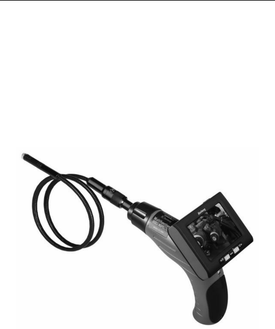
DCS400T/ DCS400R Multifunction video inspection has been designed as a user friendly and economical
way of solving hidden problems and increasing productivity. (eg. Inspect vent pipe and system of air conditioner,
machine equipment, engine and so on).
The product has a high clarity color LCD of 3.5 ’’ size. The camera head is connected to the probe and
with adjustable LED lights, which helps you to reach gaps and holes.The camera head has equipped with several
accessories, which makes it flexible. The magnetic tip is used to pick up small metal objects. The mirror tip is
easy to view the 90 ° angle. The hook is used to grab onto objects.
DCS400T/ DCS400R can take a photo wirelessly .It has built-in polymer lithium battery, also could use
AC adapter for charging with LED indicator. The screen can detach from grip, the back inside magnet facilitate
hands-free operation, having functions of Micro SD interfaceTV output interfaceUSB interface, supporting
cameravideoimage zoomrotationcomputer connection .etc. It has the advantages of small sizeclear image
stable performanceeasy operation and portability. It is widely used in applications such as the industry, the
building, the aviation, the vehicles maintenance.
Safety Instructions
Failure to follow the instructions listed below may result in electric shock or personal injury.
Read and understand all instructions prior to any operation.
Do not remove any labels from the tool.
Keep the work area clean and well lit, cluttered and dark areas may cause accidents.
Do not operate the tool with the presence of flammable/explosive gases.
Do not use the product around corrosive chemicals, which can ruin the picture quality.
Keep bystanderschildren and visitors away while operating the tool.
Stay alert, watch what you are doing and use common sense. A moment of inattention will result in serious
personal injury.
Do not overreach. Keep proper footing and balance all the time.
Always wear protective eyewear. Dust masknon-skid safety shoeshard hat or hearing protection must be used
for appropriate conditions.
Do not place this product on any unstable cart or surface. The product may fall causing serial injury to a person
or serious damage to the product.
For safety please always keep the video inspection away from any kind of liquid. Liquid increases the risk of
electrical shock and damage to the product.
2
Do not use this device for personal or medical use.
The unit is not shock-resistant. Do not use it as a hammer or drop it.
Battery precautions
Please use the standard factory power adapter, otherwise will destroy the inside battery.
Plese completely exhaust the power for the first time. And we recommend full charging and full discharging
for the first three times. And the charging time should not less than 12 hours. Fully activate the battery could play
maximum capacity of the built-in battery.
The charging and discharging time differs because the different power from the factory.
Please always keep the charging connector away from the metal and oily objects.
Please fully charging the battery before it is not for use, to make sure the high performance while using.
Don’t compress and puncture the inside battery.
Please stop operating if the inside battery is broken.
Don’t throw the product into fire, which will cause explosion.
Please dispose the battery properly. High temperature will cause the battery to explode. Please follow the local
regulations for disposing the old battery.
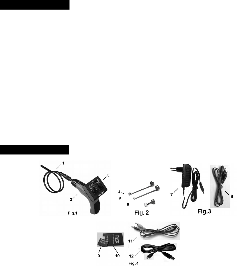
Product Configures
1Camera head and Probe
2The grip
3LCD Screen
4Magnetic tip
5Hook tip
6Mirror tip
7DC adapter
8One into two cable
9Micro SD memory card
10Micro SD to SD transition pocket
3
11TV cable
12USB cable
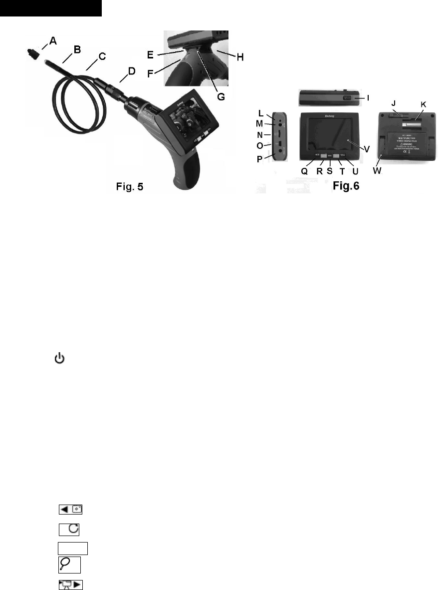
Tool components
ACamera protection
BCamera head
CProbe
DProbe connector
EPower indicator——Green lights means normal power; Red light means low battery.
FSwitch / Wheel button to adjust the LED brightness
GCharging light indicator
HCharging interface
I
JLock buckle
KSignal connector slot
LCharging light indicator
MCharging interface
NMicro SD socket
OUSB interface
PVideo Out
Q
R
SMENU
T
U
VLCD screen
4
WBase stand—facilitate hands-free operation
Descriptions for keys
Keys View mode Playback mode Menu set
Switch into playback
mode; Hold for 3s to
turn off the unit.
Switch into view mode; Hold for 3s
to turn off the unit.
Hold for 3s to turn off the
unit.
MENU Switch into menue set.
Switch into current file
operation,delete singleall
format
the memory card .etc
Set functionsset date and
time
Take a photo
yourself
Show the last photo or video; Moving to left;
Take a video Show the next photo or video; Moving to right
Image rotation Playpause the video file; Moving up / progressive
increase data and time;
Image magnify Stop video file; View six files or
six folders.
Moving down / progressive
decrease data and time;
Operation Instructions
Battery Charging
1Connect the DC cable to the grip or screen.
2Plug the AC plugs to household power outlet.
3The LED L turns red ,means charging.
4The LED L turns green, means fully charging
5Pull out the AC plug of adapter.
NotesIf you want to charge both the grip and screen, please use one to two cable. One end to the adapter, and
the other end to screen and grip.
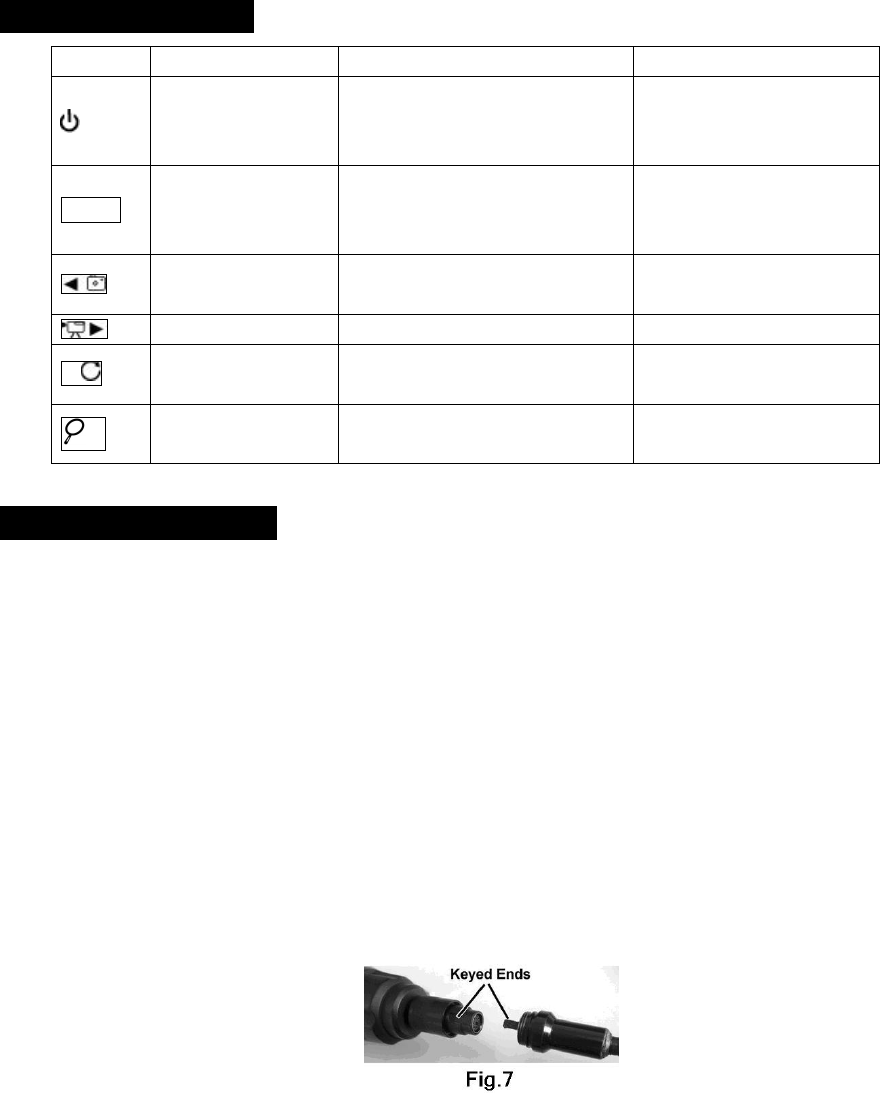
Connect the display unit to camera head and probe
The inspecting grip must be connected to the camera head and probe. To connect the probe to the grip, make
sure the keyed ends are properly aligned. (Fig7). Once they are aligned, finger tighten the nut.
Accessories installation
If you need to use the three accessories as FIG2 (magnetic tiphook tipmirror tip), please accord the steps
followed to connect.
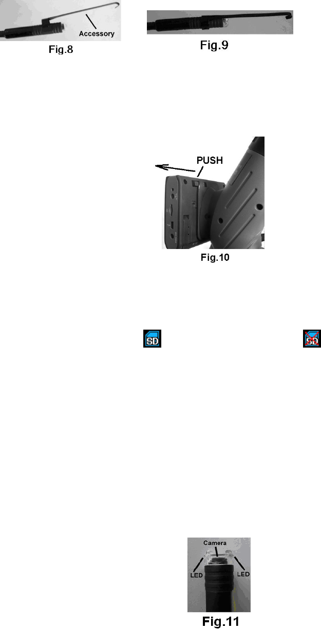
5
As showed in Fig 8, hold the camera head .Slip the semicircle end of the accessory over the flats of camera
head . Then rotate the accessory 90°to fix ,as shown in Fig9.
Connect the grip to screen
The product can work both the grip detach from screen and the grip attach with screen; Slide the slot at the
back screen into the slot of grip in the left direction until you hear the locking sound, which means connection is
finished. Press the lock buckler and slide to the right direction to detach the screen (FIG.10).
NoteThe wireless function is off while the product works with screen on the grip, which ensures the image
quality not interfered by outside.
Install Micro SD card
When the SD card inserted correctly, display on the screen; Otherwise display .
U-disk function to computer
The USB interface on the screen could connect to computer for use. When insert the memory card, it can be
considered as a U-disk; When connect the USB2.0 cable to computer and power on, the LCD displays”MSDC” ,
now the screen can be used as U-disk.
Video output
If you want to view image from television, please connect the VIDEO OUT of screen to VIDEO IN of
television by video out cable, now the screen is off.
How to work
1How to operate the grip
aRoll the button on the grip towards the probe directtion to power on.
bContinue to roll the button to adjust the brihtness of the camera LEDS (FIG.11).
6
2How to view the screen
aInsert the Micro SD to slot of memory card correctly.
bPress to enter view mode, the screen automatically find the image signal. When the same receiving
and transmission frequency occures, it is time to view image.The default chanel is CH12414MHZ
c Press to take a photo (but no function key if no card), the files with be stored in memory card
itself .
dPress to start record image (but no function key if no card), with red icon on the up screen, the
files with be stored in memory card itself .
ePress for image rotation, every press to rotate 180°.
fPress for zoom from 1 to 3.2 times with corresponding number indicator.
gPress MENU to enter menu set.
hPress to enter playback mode (with indicators if no card or no files).
iHold for 3s to turn off the product.
NoteThe screen turn off itself if no signals in 3 minutes.
TipsWhen the system is on work ( especially in video status), HotSwappable of SD card will damage the
stored files or damage SD card, please carefully operate.
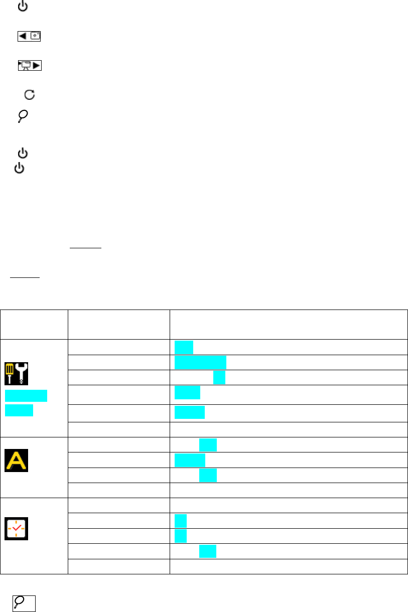
3How to set screen Menu
aIn view status, press MENU to set menu.
bSelect the menu by pressing the four direction keys.
cPress MENU to confirm the selection.
dPress EXIT back to the last menu until enter view mode.
eAs showed in the followed table for set ( The color selection is factory set).
Function
Menu
Menu Selection Selection Parameter
Advanced
Setting
Tuner Channel CH1CH2CH3CH4EXIT
Photo Quality High QualityStandard QualityLow QualityEXIT
Movie Quality QVGAD1EXIT
TV Output Standard NTSCPALEXIT
Language EnglishFrenchSpanish
EXIT
Auto Capture
Auto Capture ONOFFEXIT
Master Capture Photo 1Photo 3Movie 5sMovie 10sEXIT
File OverWrite Setting ONOFFEXIT
EXIT
Set Time/Date
Set Time/Date YY/MM/DD
Photo TimeStamp OnOffEXIT
Moive TimeStamp OnOffEXIT
Resume to factory set Yes No
EXIT
4How to operate Playback modeNo selection if no memory card.
aPress to display the inside six images, press again to display display different folders.

7
bPress MENU to scan files or folders.
cPress or to view the last or next image.
dIf it is video file, press to play video, press again to pause; Press to stop.
ePress MENU to play files, press direction keys to select delete singleall or format the momery card.
fSelect EXIT to return to last menu until to playback mode.
gPress to return to view mode.
Notes: While play video, press to play and pause video; Press once again to resume to play; Press
to stop and exit for other operations.
5This product is designed for hard-to reach distance inspection. Typical applications include HVAC inspection
car inspectioncircuitryvessel and aircraft. While in operation, the product is easy to extend ahead. If there is
distance limitation, the accessories could be used to pick up the ring or screws on the floor.
Operation Pecautions:
aPlease read the safety instructions carefully, choose desirable work area for fear causing danger.
bThe probe is flexible to help you operate in hard-to–reach areas. Please don’t insert or bend by force.. Please
do not overbend any part of the probe.Normally, the bending radius should more than 5cm to prevent from
causing permanent damage to the probe.
cDon’t use the probe or camera head to modify surroundings, clear pathways or clogged areas. It couldn’t be
used as a fishing rod or tape.
dThe hand-held display unit is not waterproof .The camera head and its cover are waterproof, but not
acid-proof or fireproof. Don’t touch with these materials or they will ruin the camera head’s protective plastic.
Avoid submersing the camera head into corrosive, oily places or high-temperature objects.
eDon’t place the inspection into anything or anywhere that may contain a live electrical charge. Please check
following methods to avoid injury.
For walls:For inspecting the inside walls, be sure to shut off the circuit breaker to the whole house
before using the tool.
For pipes:If you suspect a metal pipe could contain an electrical charge, have a qualified electrician
to check the pipe before using. A ground circuit, in some cases, can be returned to the cast
aluminium pipes and cause them to be charged.
For automobilesBe sure the automobile is not running during inspection. Metal and liquid under the
hood may be hot. Don’t get oil or gas on the imager head.
Operation Notes
Please don’t operate this product unless the manual has been read and proper training has been completely.
The red LED will on when low battery of the inside battery of grip; The “ ”displays if low battery of
screen.

8
Don’t immerse the grip inspection into water, which will result in electric shock and damage.
Only while the product is assembled well, the camera head is water-proof, but the grip and the screen isn’t
water-proof.
Don’t use the product if white dew forms inside the camera head.
If the tool couldn’t work well after turning it on. Please stop use and have the unit checked by a
qualified technician.
Store idle product out of reach of children and other untrained persons. The tool is dangerous in the hands of
untrained users.
Maintain the inspection tool with care. If the tool is dropped, check for the breakage ,which may affect the
tools’s operation. If it is damaged, have the tools serviced before using. Many accidents are caused by poorly
maintained products.
Use only accessories that are recommended by the manufacturer for your product. Accessories are suitable for
the tool, but may become hazardous when used on another product.
Dry your hands before turning the tool ON or OFF.
Protect against excessive heat. The product should be kept away from heat sources, such as radiatorsheat
registersstoves or other products (including amplifiers) that produce heat. Don’t use the tool near moving
machinery or areas where the temperature is exceed 45 .
Please cover the camera protection while not in use.
Store the product in ventilated and dry places.
Maintenance Instructions
Product service must be performed only by qualified personnel. Performed by untrained personnel could result
in injury.
When servicing the product, only use identical replacement parts. Use of authorized parts or failure to follow
maintenance instructions may create a risk of electrical shock or injury.
Don’t attempt to disassemble the product other than the needs specified on this manual.
Provide proper cleaning: don’t use acetone to clean the product. Gently clean the LCD with a soft dry cloth.
Upon completion of any service or repair, please ask the service technician to check if the tool is in proper
condition.
Stop using the unit if it starts smoking or emitting noxious fumes.
Please ask qualified person under the following conditions:
aIf liquid has been spilled or objects have fallen into product.
bIf product doesn’t operate normally even if you have followed the operation instructions.
cIf the product has been dropped or damaged in any way.
9
dWhen the product exhibits a distinct change in performance.
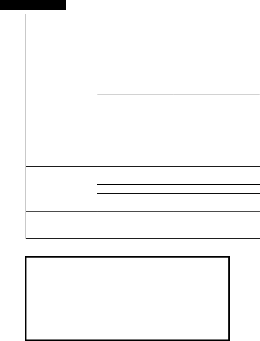
Trouble Shootings
Problems Causes Solutions
Can’t charge.
Adapter didn’t connect well
with the product.
Please check and try again.
The connect or or cable is
broken.
Replace and try again.
Dead battery Ask a technician to replace the
batter y.
The screen is on but
without image or shows
“No Signal”
1Different chanel set
between the grip and screen. Set the same chanel.
2The probe is loosed. Check and connect again.
3Stains on the camera head. Check if exists stains
LED lighting appears to be
dimmer at maximum;
Display changes from
black to white, after one
moment the color screen
shut off itself.
Low battery Use adapter for charging
The product couldn’t
power on.
The circuit is in protection
status.
Use adapter for charging to
release.
Low energy of inside battery Use adapter for charging
Dead battery Ask a technician to replace the
batter y.
Unusual display or invalid
keys
Interference to the screen or
voltage fluctuation.
Please use the reposition key
inside the hole below the stand
base.
Cautions
Don’t drop the product or use by force.
Don’t disassemble the product to avoid failure.
Don’t place the product with corrosive gas or objects.
Don’t expose the product in vibrative high or low temperature.
Store the product in a safe area.
Don’t immerse the product into water, which will result in damage to product.
Please charge the inside battery every three month ifno use for long time.

10
Technical Specifications
Name Wireless radio transmitter/wireless radio
receiver
Model DCS400T/ DCS400R
Recommended use Indoor
Viewable angle 60°
Focal length 50mm
Diameter of camera head 12mmor other size
Image display 3.5TFT/LCD
Image storage media 2G Micro SD card (Support up to 16G
LCD Resolution 320×240 pixels
Wireless
transmission
frequency
Emission frequency 2414MHz
Receiving frequency 2414MHz2432MHz2450MHz2468MHz
Wireless transmission distance Up to 10M; If no obstacles, will more than
10M
Accessories
Magnet tiphook tipmirror tipMicro SD
cardone to two cableMicro SD memory
cardMicro SD to SD transition pocket
TV cableUSB cable
Probe length 100cm or your requirements
Probe and camera head protection IP67
Light source High lighting LED
Adapter INPUT AC 100240V5060Hz
OUTPUT DC 5.5V 1.5A
Inside battery Polymer Lithium battery
Battery
capacity
Grip 1400mAh
Screen 1350mAh
Charging time of inside battery About 3.5 hours
Battery life About 2 hours
Operating temperature 045
Operating humidity RH 5%95% non-condensing
Storage temperature -20+6085%w/o battery
Dimension Grip 215mm×175mm×50mm
Screen 100mm×82mm×26mm
Weight Grip About 228 gw/o probe
Screen About 175 g

11
Warranty
The product is warranted to be free from defects in materials and workmanship for a period of one year
from the date of purchase.
Notice: The warranty does not apply to the following conditions:
Disassembling the laser tool will void the warranty.
We are not responsible for any damage resulting from abrasion, water, dropping or disassembling.
TipsMost parts of the product could be recycled, please refer to your local regulations for disposing of them
instead of throwing into the dustbin.
Warning
This device complies with Part 15 of the FCC Rules. Operation is subject to the following two conditions:
(1) This device may not cause harmful interference and
(2) This device must accept any interference received, including interference that may cause undesired operation
Changes or modifications not expressly approved by the manufacturer responsible for compliance could void the
user’s authority to operate the equipment.
NOTE: This equipment has been tested and found to comply with the limits for a Class B digital device, pursuant to
part 15 of the FCC Rules. These limits are designed to provide reasonable protection against harmful interference
in a residential installation. This equipment generates uses and can radiate radio frequency energy and, if not
installed and used in accordance with the instructions, may cause harmful interference to radio communications.
However, there is no guarantee that interference will not occur in a particular installation. If this equipment does
cause harmful interference to radio or television reception, which can be determined by turning the equipment off
and on, the user is encouraged to try to correct the interference by one or more of the following measures:
—Reorient or relocate the receiving antenna.
—Increase the separation between the equipment and receiver.
—Connect the equipment into an outlet on a circuit different from that to which the receiver is connected.
—Consult the dealer or an experienced radio/TV technician for help.