GENIE Garage Door Opener Manual L0910369
User Manual: GENIE GENIE Garage Door Opener Manual GENIE Garage Door Opener Owner's Manual, GENIE Garage Door Opener installation guides
Open the PDF directly: View PDF ![]() .
.
Page Count: 32

!!
Check your ceiling where the power
head of your new unit will be mounted.
Plan how you will be mounting the power head.
It is possible that ceiling joists may not be in the
exact position needed with respect to the garage
door operator. In any case, it may be necessary
to add an additional bracket and fasteners (not
included with your new door operator kit).
You need a 110-120 Volt power supply
available. If you plan to plug the unit into a
standard electrical outlet, is one available? The
outlet should be no more than about 3 feet from the
power head once it is mounted. (The cord is 4 ft, in
length.) SEE WARNING BELOW.
Check the wail directly above the garage
door. The door operator's header bracket
must be securely fastened to this wall. Insure
that the structure will provide a strong mounting
location.
Check to see if the mounting location
for the Safe-T-Beam ® System (STB) is
clear from obstruction and has a wood
surface available for attaching the STB
brackets. The brackets may also be attached to
concrete if necessary but extra tools and special
fasteners (not supplied) will be required.
s_"esws _;i_be th_"o_ 9h yo_ _"oc_:s Gene/3e_-:s e_"
Is your garage door made of
light-weight steel, aluminum, fiberglass
or glass panels? Additional support bracing
must be added to these type doors, If this is the
case, please contact the door distributor or
manufacturer so that they can furnish you with a
"bracing kit."
To avoid damage to your door and/or
operator, make sure you disable any door
locks prior to installing your operator.
Insure that your door is properly balanced
and moving freely. SEE WARNING BELOW.
(NOT SHOWN) If your garage does not have
a separate entry door, you might want to
consider an emergency release kit (GER-2) for
installation on your garage door. See page 30.
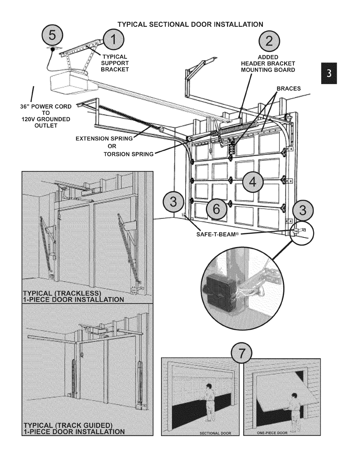
TYPICAL SECTIONAL DOOR iNSTALLATiON
/
36" POWER CORD
TO
120V GROUNDED
OUTLET
SUPPORT
BRACKET
EXTENSION SPRING
OR
TORSION SPRING
ADDED
HEADER BRACKET
MOUNTING BOARD
BRACES
SAFE-T=BEAM®

OVERVIEW OF
POTENTIAL HAZARDS
Garagedoorsarelarge,heavyobjectsthatmovewiththehelpof springs
underhightensionandelectricmotors.Sincemovingobjects,springsunder
tension,andelectricmotorscan causeinjuries,yoursafetyandthesafetyof
othersdependon youreadingtheinformationinthismanual.Ifyouhave
questionsordo notunderstandtheinformationpresented,callyournearest
servicerepresentative
In thissectionandthosethatfollow,the wordsDanger,Warning,and
Cautionareusedto emphasizeimportantsafetyinformation.
Theword:
_,DANGERmeansthatsevereinjuryordeathwill resultfromfailure
tofollowinstructions.
_,WARNINGmeansthatsevereinjuryor deathcanresultfromfailure
tofollowinstructions.
_.CAUTION meansthatpropertydamageorinjurycanresultfromfailure
tofollowinstruction.
Theword#,;OTli_is usedto indicateimportantstepsto befollowed
orimportantconsiderations.
Safe-T-Beam ® (STB) Non-Contact Reversing System
IMPORTANT
INSTALLATION
INSTRUCTIONS
Toreducethe risk of
severe injuryor death:
1. READAND FOLLOWALL SAFETY,INSTALLATIONAND
OPERATIONINSTRUCTIONS.If you haveanyquestionsor
do notunderstandan instruction,callyour service
representative.
2. Do Not installoperatoron animproperlybalanceddoor.An
improperlybalanceddoorcouldcausesevereinjury.Repairs
and adjustmentsto cables,springassembly,andother
hardwaremust bemadeby a trainedservicepersonusing
propertoolsandinstructions.
3. Removeall ropesand disableall locksconnectedto the door
before installingoperator.
4. Installdooroperator7feet or moreabovethe floor. Mountthe
emergencyreleaseknob6 feetabove thefloor.
5. Do Notconnecttheoperatorto the sourceof poweruntil
instructedto doso.
6. Locatethe controlbutton:
• Withinsightof door.
• At a minimumheightof 5 feet,so small childrencannot
reachit.
. Awayfrom all movingpartsof thedoor.
InstalltheentrapmentWARNINGlabelnextto thewallbuttonor
console.Installthe emergencyreleasetag on,or nextto, the
emergencyrelease
Theoperatormustreversewhenthedoorcontactsa 1-1/2inch
highobjecton thefloor at the centerof thedoorway.Thisis about
thesize of a 2" x 4" boardlaidflat.
Places an invisible beam across door opening that reverses the door during down travel to the fully open
position if anything passes through beam.
Safe-T-Reverse ® Contact Reversing System
Automatically stops and reverses a closing door within 2 seconds of contact with an object.
Safe-T-Stop ® Timed Reversed System
Automatically opens a closing door, if door does not close within 30 seconds.
Force Guard ® Control
Used to set the force required for opening and closing door. For maximum safety, set the minimum force
required to fully open and close door.
Automatic Lighting System
One or two light bulbs (depending on model) up to 100 Watts max. each are used for safer entries and exits.
The light turns on when door is activated and automatically turns off 4.5 minutes later.
Manual Emergency Release
Allows the garage door to be opened or closed manually for emergencies or maintenance.

@@
@remotes
vary by model
_ Immmm
i!_L _ _ ,, .:i :i_:L:,_I
, _ "., !i¸¸ _ :Lui
@
FASTENERS -Shown full size. See Parts List for description.
Bolt, #10-24 x 1/2"
--'m
Bolt, 5/16"-18 x 1/2"
Phillips Hex Head Screw, No. 10 x 1-1/4"
1/4"-20 x 3/4"
Self-Drilling Screw
Bolt, 3/8"-16 x 7/8"
Insulated Staple
Pan Head Screw #6 x 1-1/4"
Pan Head
Phillips Screw
No. 8 x 5/8"
aa _ _ D
Hex Head Screw
Lag Screw, 1/4" x 2" Clevis Pin No. 8 x 3/4"
Speed Nut Cotter Pin
m
Z
Cold Head Pin
Ii


.Fasten rail to power head.
•Align mounting holes of sprocket saddle, rail
and power head frame.
•Insert the two (2) 5/16" x 1/2" hex head
screws[112], then two (2) No. 10-24 x 1/2" hex
head screws [69].
•Tighten screws.
_:opower h®<_;_d_o py_:w de p_'_perwhe ,J_ssen'MF_g "
• @Fs? ......... ,_,
6. Use adjusting bolt to set chain tension (Fig. 1-4)
• Chain should sag slightly but not so much that it
drags on the rail.
IMPORTANT
iNSTALLATION
INSTRUCTIONS
To reduce the risk of
severeinjuryor death:
1. READANDFOLLOWALL SAFETY,INSTALLATIONAND
OPERATIONINSTRUCTIONS.If you haveanyquestionsor
do notunderstandan instruction,callyourservice
representative.
2. Do Not installoperatoron an improperlybalanceddoor.An
improperlybalanceddoorcouldcausesevereinjury.Repairs
and adjustmentsto cables,springassembly,and other
hardwaremust be madebya trainedservicepersonusing
propertoolsandinstructions.
3. Removeall ropesand disableall locksconnectedto thedoor
before installingoperator.
4. Installdooroperator7feet or moreabove thefloor.Mountthe
emergencyreleaseknob6 feetabove thefloor.
5. Do Not connecttheoperatorto the sourceof poweruntil
instructedto doso.
6. Locatethecontrolbutton:
• Withinsight of door.
. Ata minimumheightof5 feet,so smallchildrencannot
reachit.
. Awayfrom all movingpartsof the door.
7. InstalltheentrapmentWARNINGlabelnext to thewall buttonor
console.Installthe emergencyreleasetag on,or nextto, the
emergencyrelease.
8. Theoperatormustreversewhenthedoorcontactsa 1-1/2inch
highobjecton thefloor at the centerof thedoorway.Thisis about
the sizeof a 2" x 4" boardlaidflat.
Track Guided Doors
SEE SECTION 2A
Section Door With 1-Piece Door With
Curved Track Hardware Horizontal Track Hardware
/_/ StraightTrack
] (HorizontalOnly)
'U"
Trackless Doors
SEE SECTION 2B.
1-Piece Door
Jamb TypeHardware
(No Track)
yi:÷-
iT"
"U"
1-Piece Door
Pivot Type Hardware
(No Track)
"U"

1. Establish center line of door and header (Fig. 2-1).
•Close door,
•Measure door width. Mark center.
•Use straight edge to draw vertical line "V."
- down door about 6".
- on top of door.
- up header about 20".
2. Establish Header Bracket position (Fig. 2-2).
•Watch top edge of door as you raise it.
•Stop door when top edge reaches highest point
of travel.
•Measure distance from top edge of door to floor.
•Add 2-1/2" to this measurement.
•Close door.
•Mark header at this height.
•If door spring is in the way, mark header 2-1/2"
above the spring.
•Draw horizontal line "H" across line "V" at this
point (Fig 2-1).
NO_E:: _:_!_d_,rbf_'._cl<eJmus_ be _/_i,_s_>2,,4/2 >_bow_,
hi_i_hpo#:_ _of d_:>o__w'e £ can be _:nsS3_edhi_i_hef £
doo_ sphr £ Ls M_'hes,;':_y_Do No move _'hesph,n£
Line "V"
(Vertical Center Line
of Door) Line "H" Can Be
Spring
Line "H"
Door
Header Inside of Door
Mark
Header
Or
Above
Spring
Header
Door
NOTE: Line "H" Can Be
Drawn Above Spring
Spring Line "H"
Add 2-1/2"
Minimum High Point
,Of Door Travel
Door Track
Measure To Floor

3. install header bracket (Fig. 2-3)
•Place bracket so:
- center hole is on line "V."
- all holes are on line "H."
• Mark hole positions "A" and "B."
• Drill 5/32" holes at marked positions.
• Fasten bracket to header using two (2) 1/4" x 2"
lag screws [79].
4. Attach channel/rail assembly to header
bracket (Fig. 2-4).
•Fasten header end of the channel/rail to the
Header bracket with cold header pin [82].
•Install speed nut [81].
•Support power head above floor, use:
- rope.
- ladder with cardboard packing.
- wood.
5. Level rail assembly and power head (Fig. 2-5).
•Raise and support power head above door tracks.
•Open door.
•Level channel/rail assembly and
support temporarily.
•Center channel/rail assembly and power head
on line "V" of door.
should be h_ve ff pess£_Fe ff necessuy, po_<_,r
head may be moun_,d fo_,r: _,,fo'_:_,yermouni',ed,
mevi_ £ doer must no _'ouc_ c_ anne_'_/ assembJy_
6. Mount power head
(See Section 2 MOUNTING METHODS).
•Be sure channel/rail assembly and power head
are on door center line (Line "V').
•Check the illustrations. Decide which mounting
method you will use. Materials for mounting are
not included.
•After power head is installed, remove
supporting material.
•Close door.
7. Install door braces (See CAUTION below).
T-rail shown. Channel
attachment is same.
Header
Bracket
Speed nut
[81]
Cold header
Header
Door
Supportifyto
clearsprmg
Power Head
Channel/Rail
Assembly \
Center Line

Top of Door
@
Top of Door
8. Install door bracket (Fig. 2-6).
,Contact door manufacturer.
9. Install door arms (Fig. 2-7).
• Attach straight door arm to carriage.
- slip straight door arm into slot at bottom of
carriage as shown.
- secure with clevis pin [90] and cotter pin [89].
• Attach short end of curved door arm to door
bracket as shown.
- slip short end of curved door arm into slot in
door bracket.
- secure with clevis pin and cotter pin.
• Release carriage (See emergency release tag).
- slide carriage towards closed door.
- stop carriage 14" minimum from door.
10. Join door arm sections (Fig. 2-8).
Use two (2) 3/8" x 7/8" hex bolts [91], and hex
flange nuts [92].
- use any two holes as far apart as possible.
- slide carriage back and forth as needed to
align holes.
•Tighten hex nuts securely.
11. Adjust emergency release cord length.
•Mount the emergency release knob 6 feet from
the floor.
•Retie overhand knot and trim excess cord.
DO NOT plug power cord into outlet.
Go to Section 3-SAFE-T-BEAM ®
SYSTEM INSTALLATION.
I
I
I
OR
Top of Door
14" MIN. %
Straight door arm
Curved door arm
Straight door arm
Curved door arm [92]
3/8-16 nut

1. Establish center (ine of door and header (Fig. 2-9).
•Close door.
•Measure door width. Mark center.
•Use straight edge to draw vertical line "V."
- down door about 6."
- on top of door.
- up header about 20".
2. Determine door rise (Fig. 2-10).
•Open door to highest point of travel.
•Measure distance from top of door to floor.
•Subtract the actual height of door. The remainder
is the door rise in inches as shown in TABLE A.
TABLE A
Door rise
in inches
Up to 4"
4" to 8"
8"to 12"
Locate header bracket above
top edge of CLOSED door
Upto 10"
10" to 15"
15" to 20"
.Locate header bracket (Fig. 2-9).
•Use TABLE A to determine header
bracket position.
• Draw horizontal line "H" across line "H" at
this point.
.. install header bracket (Fig. 2-11).
• Place header bracket so,
- center hole is on line "V."
- all holes are on line "H."
•Mark hole positions ("A" and "B").
•Drill 5/32" holes at marked positions.
•Fasten header bracket to header with two (2)
1/4"x 2" lag screws [79].
Line "V"
(Vertical centerline of door) See
I
I
Inside of door
Top of door
Door rise
?
Highest point Highest point Door rise
of trave, of traveL._ _
Floor

5. Install door braces
(See CAUTION below).
Attach channel/rail assembly to header
bracket (Fig. 2-13).
•Fasten header end of the channel/rail to the
header bracket with pin.
•Install speed nut onto pin (Fig, 2-14).
•Place cardboard packing under power head. Use
additional support if needed.
.
Establish power head mounting height (Fig. 2-15).
•Power head should be at door height above floor
or higher.
•Temporarily support power head in this position,
Use
.
Header
Door
bracket
Power head
(Protected by cardboard
or packing)
-rope.
- ladder with cardboard packing.
- wood.
Critical height is point where the rail/channel attaches to power head.
CORRECTf
m
.......!ii!_i'ii_i_!ii!'i_i!7!i!!'i_i!!J!_i_i!!i!i'i:ii!i!!_i_i!!i!!'i_i!!i!i_i_i_!i!!'i:i!!i!!_i_i_!i!!'i:i!!i!!_i_i_!i!!'i:i!!i!!_i_i_!i!!'i:i!!i!!_i_i_!i!!'i:i!!i!!_i_i_!i!!'i:i!!i!!_i_i_!i!!'i:i!!i!!_i_i_!i!!'i:i!!i!!_i_i_!i!!'i:i!!i!!_i_i_!i!!'i:i!!i!!_i_i_!i!!'i:i!!i!!_i_i_!i!!'i:i!!i!!_i_i_!i!!'i:i!!i!!_i_i_!i!!'i:i!!i!!_i_i_!i!!'i:i!!i!!_i_i_!i!!'i:i!!i!!_i_!_!!_:_!!_!!_i_!_!!_:_!!_!!_i_!_!!_:_!!_!!_i_!_!!_!_!!_!_!_!!_!!_i_i_!_!_!!_!_i!_!!_i_!!_i_!!_i!_i:_i!_!!_i_i!i!7_i!_!!_i_!!_i!_!!_!!_i_!!_i!_i!_!_i_!!ii!_i!_!!_i_!_!!_i_i7!_i_!!_i!_i!_!_i_!!ii!_i!_!!_i_!_!!_i_i7!_i_!!_i!_i!_!_i_!!ii!_i!_!!_i_!_!!_i_i7!_i_!!_i!_i!_!_i_!!ii!_i!_!!_i_!_!!_i_i7!_i_!!_i!_i!_!_i_!!ii7_i!_!!_i_i!_!!_:_

9. Mount power head (See Section 2 ALTERNATE
MOUNTING METHODS).
•Be sure rail assembly and power head are on
door center line (line "V').
•Check the illustrations. Decide which mounting
method you will use. Materials for mounting are
not included.
•After power head is installed, remove
supporting material.
•Close door.
10. Join door arms exactly as shown (Fig. 2-16).
•Overlap arms by two (2) holes.
•Install two (2) 3/8" x 7/8" hex bolts, and hex
flange nuts.
,, Tighten hex nuts securely.
11. install assembled door arms (Fig. 2-17).
•Attach straight end of assembled door arms to
door bracket.
-slip straight door arm into slot in door bracket.
-secure with clevis pin [90] and cotter pin [89].
, Release carriage (See emergency release tag).
•Slide carriage toward door.
•Attach short end of curved door arm to carriage.
- slip curved door arm into slot in carriage.
- secure with clevis pin and cotter pin.
12. Adjust emergency release cord length.
•Mount the emergency release knob 6 feet from
the floor.
•Retie overhand knot and trim excess cord.
ht door arm
[91]
,, Bolt, 3/8-16 x 7/8"
/"
[92]e' ,-"
3/8-16 nut O/
Curved door arm
Clevis pin
Cotter pin

Fs F_s _ ;ed
.Mounting brackets.
• Mark both sides of garage door frame or wall 5"
above floor (Fig. 3-1).
• Hold bracket against door frame or wall.
- Check if brackets extend out from wall far
enough, so tongue of bracket is beyond door,
tracks or any door hardware.
- If not:
a. STB bracket extensions are available at
local dealer.
b. Blocks of wood, etc. may be substituted
for extensions.
• Center bracket on your mark (Fig. 3-2).
• Fasten each with 2 screws [127].
[127] #10-16xi-1/4,,
2, Mounting STB source and sensor.
• If garage has only one garage door.
- Determine which side of garage receives
most direct sunlight (Fig. 3-4).
- Red LED should always be on sunny side
whenever possible (Fig. 3-4).
• For multiple doors.
- Preventing crossed signals is critical.
- Place source and sensor modules on
adjacent doors facing in opposite directions
(Fig. 3-4).
• Slide source/sensor onto tongue of bracket
until it clicks into place (Fig. 3°3).
,Wiring.
• Routewire using either method shown(Fig. 3-5).
• Securely fasten wires to wall as you go.
- Use insulated staples (included).
[128] Insulated staple
- Staples should be snug only.
ONE DOOR
GARAGE
TWO DOOR
GARAGE
THREEDOOR
GARAGE
Dashed Line = striped wire
Solid Line = white wire
Source
A
1
I
Power
Head
I i.
Source
Power
Head

•Make wire attachments at STB's.
- Splitting and stripping wire ends to be
connected as shown (Fig. 3-6).
- Loosen terminal screws.
- Insert wire under flat plate and tighten screw. It
does not matter which wire, white or striped,
goes on which terminal (Fig. 3-7).
•Make wire attachments at power head.
- For ProMax. STB's are connected to terminals
#2 and #3 on power head (Fig. 3-8).
- For Stealth. STB's are connected to
terminals #3 and #4 on power head (Fig. 3-8).
4. Check the following.
• Insure that no part of door or its hardware is in
path between lenses of source and sensor.
• Insure that tops of lenses are between 5"-6"
above the floor (Fig. 3-9). The brackets are
flexible and can be adjusted slightly if needed.
DO NOT _LUG N_TT,!
To correct the problem - the brackets are
flexible and can be adjusted slightly to bring
the system into alignment.
When the STB's are in alignment the red LED
will stop blinking and stay on.
SOURCE (RED LED) SENSOR (GREEN LED) INDICATED CONDITION REQUIRED ACTION
ON _ ON NORMALOPERATION NONE REQUIRED
1.POWER HEADNOT POWERED 1.CHECK BREAKERS,FUSES, PLUGS
O OFF O OFF 2.WIRING FROM POWERHEAD BAD 2.CHECK WIRING FOROBVIOUSSHORTS
1.WIRINGTO SOURCE MISSING OR BAD 1.CHECK WIRING
OFF ON
lit 2. POWERHAS BEENINTERRUPTED 2. REMOVEPOWERAND REAPPLY
1.BEAM NOT ALIGNED 2. BEAMOBSTRUCTED 1.CHECKALIGNMENT 2. CHECK FOROBSTRUCTION
2 BLINKS, PAUSE(REPEAT) _ ON &SENSOR DEFECTIVE &CALL CUSTOMERSERVICE
1.WIRETO SENSORMISSINGOR BAD 1.CHECK WIRING
2 BLINKS, PAUSE(REPEAT) O OFF 2.SENSOR DEFECTIVE 2.CALL CUSTOMERSERVICE
Du_o_"_'"_,PAUSE(REPEAT) _ ON 1.SENSORRECEIVINGINTERFERENCE 1.ATTEMPTTODETERMINESOURCEOFINTERFERENCE3 2.CALL CUSTOMERSERVICE
1. SOURCENOT SENDING PULSES 1.CALL CUSTOMERSERVICE
4 BLINKS, PAUSE(REPEAT) _ ON 2.SOURCE DEFECTIVE 2.CALL CUSTOMERSERVICE
NOTE: IF OPERATING PROBLEM EXISTS, THE DOOR CAN BE CLOSED IF YOU: 1. DISCONNECT THE STB SYSTEM FROM THE OPERATOR AND 2. HOLD WALL CONTROL BUTTON
DOWN UNTIL DOOR IS CLOSED. (REMOTE CONTROL & WIRELESS KEYPAD WILL NOT WORK WITHOUT STB)
CUSTOMER SERVICE: 1.800.354.3643 or www.geniecompany.com

.
.
3.
.
5.
Run wire from power head to wall control.
, Place the wall control:
- In sight of door.
- At least 5 feet from floor, so small children can
not reach it.
- Away from moving parts of door and
door hardware.
• Use staples to fasten wire to ceiling and wall.
Remove 1/2" insulation from each wire
(Fig. 3-6)(pg. 19).
Attach wires to terminals (Stealth Fig. 4-1a)
(MAX Fig. 4-1b).
•Loosen, but Do Not remove screw from terminal.
For Stealth.
- Connect striped wires to terminal "2" on power
head and "B" on wall control.
- Connect white wire to terminal "1" on power
head and "W" on wall control.
For MAX.
- Connect striped wires to terminal "1" on power
head and "B" on wall control.
- Connect white wire to terminal "2" on power
head and "W" on wall control.
Mount wall control (Fig. 4-2).
• Use two pan head screws.
Mount entrapment warning label.
• Remove protective backing and stick near
wall control.
• Use tacks or staples to permanently mount Label.
• Make sure everyone reads and follows WARNINGS.
Vacation Locking Switch
-LOCKdisablescontrolsafterdooris completely closed
-UNLOCKallowscontrolsto worknormally
Independent Light Control
- Controls door operator lights from inside garage
- Energy-Saver shut-off turns off light 5 minutes after
door activation
_>d_': O_TLYONE OF'_>UR_LL CON'_'_OLSM_Y BE 7_E
L GH TYPS B)S_ have a _jh_,d wa] ¢0 _9[;,_3Ayou
Power head _ Striped
terminalsl lLZ,:,_l] i ,4J_l
/I '-=_ I I I I_I wall
............................ /I If_l ,_ I WhiteI I _B_ button
..............................._ <'_/._.,.. il"f_l _-I H4_JIterminals
_IT AD JUSTbI_E_ _j_
) ¢_ console
terminals
Front view of
power head
power head Back view
terminals
Wall button Wall console
J OR
/
pan head screws
Lighted Button
- Shows system is powered
- Lights when Security Lock
Switch is in UNLOCK position
when Security Lock
Switch is in LOCK position
Door Control Button
- Open and closes door from
inside garage
ii i ii i:i !!!iii !!iii !!iii !!iii i!!i

1. Check local building codes.
•Some building codes require direct wiring to a
branch circuit. If direct wiring is NOT required,
plug door operator into grounded outlet
(Fig. 6-1).
2. Return to Section 3 for SAFE-T-BEAM ®System
alignment and troubleshooting.
1. Disconnect the power cord from the branch
circuit mains.
2. Remove bottom cover from power head.
• Remove four (4) hex head screws from front
and rear covers.
• Slide bottom cover off.
3. Remove existing power cord from power head.
• Disconnect three power cord wires.
• Remove and discard power cord.
• Remove 7/8" diameter knock-out plug.
• Install a suitable entrance bushing.
4. Install permanent wiring to power head.
For Stealth--connect permanent wiring to
internal terminal block.
• Connect white supply line to silver terminal.
• Connect black supply line to brass terminal.
• Connect ground wire to green wire location
(GROUND).
For ProMax--connect permanent wiring.
• Make connections with UL recognized wire nuts.
• Connect white supply line to white wire.
• Connect black supply line to black wire.
• Connect ground wire to green wire location
(GROUND).
• Wires inside operator are to be a minimum of
6 inches.
5. Replace power head bottom cover.
• Replace and tighten four (4) hex head screws.
cover i:_ on po_:,r head befio_,!_ope_d<on
Operator
power cord
Grounded
outlet
Fig. 5-1

Before starting main limit switch settings, LOCK
carriage onto rail assembly (See emergency
release tag).
1. Raise the door until the carriage engages with
the inner-slide/bullet.
2. Set "OPEN" limit switch (Fig 6-1).
•Locate limit set switch on back of power head.
•Push and hold limit set switch until door moves
to the fully open position.
- release the limit set switch.
-"OPEN" limit switch is set.
NO_!:" !_dooy 's_'..#::_s_:mdfcdusc*s _o mov_ u_:?_d/:us_>
"OP FORC.,/_Z_ pSee Sec_-o-n 7,_FORC;E
3. Set "CLOSE" limit switch (Fig. 6-1).
•Push and hold limit set switch until door contacts
the ground and stops.
- release limit set switch.
-"CLOSE" limit is set.
NOTE; Ydoor s_ps and f_@,_,ses_'omove d%>_,'_
adjust CLOSE FORCE* _ee Section 7,FORCE
A©JUS 7_ia_d t2_ens_ea_' se_ing t7_[t sw _'ch
NOX{!; Do Not pus_ the l_m_ set s hagai_ _<_ur
S,',_<_hsam seL S;ght a<,:O_:us#_,entmay be need_;_dbi_<
_;ee Secth:;_n8,,_NE L _VT SWTFC_WADJUS
STEALTH

During the following steps, the motor protector may
open. Wait about 20 minutes for protector to reset.
C'LOSS_ pos _on befon_ s_'U_g OP_ FOF_CS
STEALTH
1. Adjust the "OPEN" Force (Fig. 7-1).
•Locate screw on back of power head marked
"OPEN FORCE."
, Gently turn screw counterclockwise until it stops.
NON_ L_o eHeT hsyequ _<ed_o u_"_'__d]_usd_g sc_q_J_
• Operate door using wall control.
• If door does not completely open, turn "OPEN
FORCE" screw clockwise slightly.
• Activate door using wall control.
• Repeat force adjustment until door will
completely open.
NOH!k Se_m nh_.:_umh:_ce required _orose doo_ c_e;_
• Close door, use wall control.
2. Adjust the "CLOSE FORCE" (Fig. 7-1). Use wal
control to run door to the fully OPEN position
before starting "CLOSE FORCE" adjustment.
• Locate screw on back of power head marked
"CLOSE FORCE."
, Gently turn screw counterclockwise until it stops.
NON_; £11h;,eR%_rlhsyequimd _o _u_'nad]_usdn£ sc_q_.
• Operate door using wall control.
• If door does not completely close, turn "CLOSE
FORCE" screw clockwise slightly.
• Operate door using wall control.
•Repeat force adjustment until door will
completely close.
NO77£/Set _'hemb_h,_um lome mquh,_d 8o make _'he
door dose Smal/e£ S'_enumber _'he smal/e£ _'he
lo_ee
PRO MAX
3. [ CONTACT REVERSE J(Fig. 7-2)
Fine adjustments for limit switches (see Section 8)
MUST BE completed before starting CONTACT
REVERSE.
•Open door, use wall control.
•Place a2 by 4 board laid flat in center of doorway.
• Close door.
• Door MUST stop and reverse to open position. If it
does not, repeat fine adjustments for down limit
switch and "CLOSE FORCE" adjustment until the
door will reverse to the open position.
If door does not reverse, decrease "CLOSE FORCE"
until door reverses.

During the following steps, the motor protector may
open. Wait about 20 minutes for protector to reset.
1. Adjusting the "OPEN" limit switch (Fig. 8-1).
•Run door to open position by pushing wall control,
•Locate curved "OPEN" limit adjustment slot on
back of power head.
•Look into slot for pinion screw.
•Insert a screwdriver and turn pinion screw.
- clockwise to open more.
- counterclockwise to open less.
2. Test door operator. Use wall control to run
door open and close.
3. Repeat step as necessary to properly set
"OPEN" limit switch.
4. Adjust the "CLOSE" limit switch (Fig. 8-1).
•Run door fully closed by pushing wall control.
•Locate curved "CLOSE" limit adjustment slot on
back of power head.
•Look into slot for pinion screw.
•Insert a screwdriver and turn pinion screw.
- counterclockwise to close more.
- clockwise to close less.
5. Test door operator. Use wall control to run door
open and close
6. Repeat step as necessary to properly set
"CLOSE" limit switch
7. Perform CONTACT REVERSE
conSuL
Remo_J;, con#_<:4s net w<c:_¢_kJ SA_s ma]Y:_,nc_/en
1. Program one-button remote (Fig. 9-1)
•Locate learn code button and learn indicator on
power head.
- Remove lens cover on back of power head.
•Press and release learn code button on
power head.
- LED on power head blinks 2 times per second.
(continued on next page)

• Press and release a remote control button.
- LED on power head stops blinking.
• Press and release same remote button again.
- LED goes out. Remote is now programmed.
2. Program multi-button remote control
• Repeat step 1 ("program one-button remote" for
each button).
3. Operate remote control
• Point remote control at door
- Door moves
• Press button again
- Door stops
• Press button again
- Door reverses
cose cyc÷
4. Erasing aJJreceiver memory
• Press and hold learn code button on
power head
- 10 seconds or until light goes out
- Memory is erased
• Program door operator again
• Press remote control button once within
30 seconds
- LED on power head stays lit
• Press remote control button again
- LED on power head goes out and remote
control is programmed
secon@ py_;_g,/_;.#_mmF_'_gh,s_ss e4 Ffpy_s_gy_;_mm_;g
Learn
indicator
Radio
Learn
o
1. Turn remote control upside down (Fig. 10-1)
2. Battery replacement (your remote control is
battery powered).
•Gently push straight IN on tab as shown
(Fig. 10-1).
- use ball point pen, coin or small screwdriver.
- battery cover snaps open.
• Install new battery in same position.
-use A23, _,EIIEREAD[ 12 Volt battery.
3. Attach visor clip to remote control (Fig. 10-2)
•Slide visor clip into back of case until it snaps
into place.
4. Remote control operation
•Point remote control at the garage door and
press the button. Door will move.
•Press remote control button again and door
will stop.
•Press remote control button again and the door
will move the other way. The door automatically
stops at the end of the open or close cycle.
Visor clip
"_-_ Battery
__ cover
_/Battery

1. install light bulb(s) into socket(s).
Do Not use short neck bulb(s).
•Use bulb(s) rated for:
- rough service.
- vibration.
- appliances.
•100 watt maximum.
2. Bend two (2) slotted tabs up. This will activate
the "living hinge" of the lens (Fig. 11-1).
3. Start two (2) No. 8 x 3/4" hex head screws into
bottom holes of panel (Fig. 11-2).
•Slide slotted tabs up behind hex head screws.
•Tighten hex head screws.
4. Align lens holes and holes of panel.
• Insert and tighten a No. 8 x 5/8" pan head
screw into each round lens hole and tighten,
Bend tabs up (2)_,__
Slotted t_
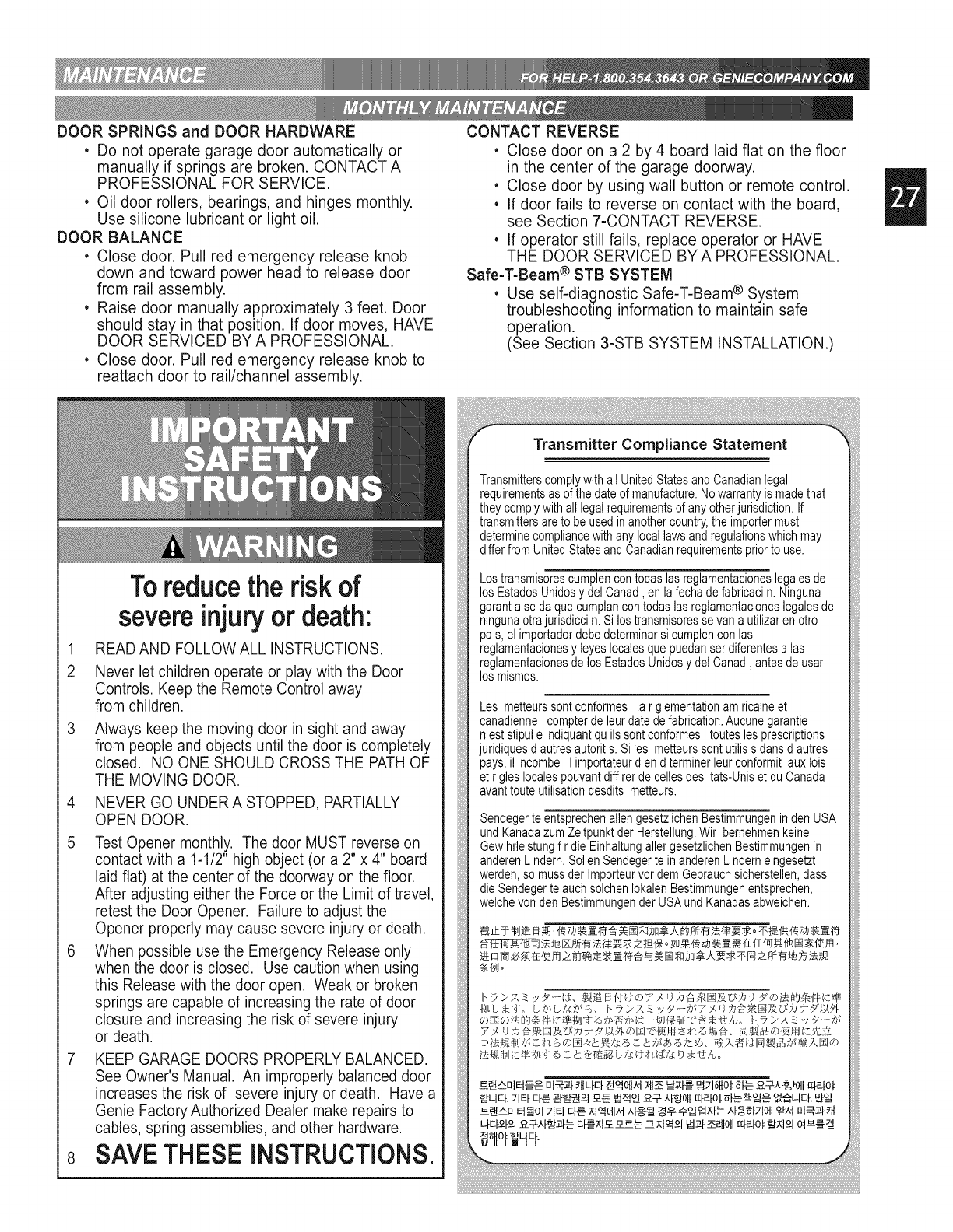
DOOR SPRINGS and DOOR HARDWARE
• Do not operate garage door automatically or
manually if springs are broken. CONTACT A
PROFESSIONAL FOR SERVICE.
• Oil door rollers, bearings, and hinges monthly.
Use silicone lubricant or light oil.
DOOR BALANCE
• Close door. Pull red emergency release knob
down and toward power head to release door
from rail assembly.
• Raise door manually approximately 3 feet. Door
should stay in that position. If door moves, HAVE
DOOR SERVICED BY A PROFESSIONAL.
• Close door. Pull red emergency release knob to
reattach door to rail/channel assembly.
Toreducethe risk of
CONTACT REVERSE
• Close door on a 2 by 4 board laid flat on the floor
in the center of the garage doorway.
• Close door by using wall button or remote control.
• If door fails to reverse on contact with the board,
see Section 7-CONTACT REVERSE.
• If operator still fails, replace operator or HAVE
THE DOOR SERVICED BYA PROFESSIONAL.
Safe-T-Beam ® STB SYSTEM
• Use self-diagnostic Safe-T-Beam ® System
troubleshooting information to maintain safe
operation.
(See Section 3-STB SYSTEM INSTALLATION.)
1
2
4
5
severeinjuryor death:
READ AND FOLLOW ALL INSTRUCTIONS.
Never let children operate or play with the Door
Controls. Keep the Remote Control away
from children.
Always keep the moving door in sight and away
from people and objects until the door is completely
closed. NO ONE SHOULD CROSS THE PATH OF
THE MOVING DOOR.
NEVER GO UNDER A STOPPED, PARTIALLY
OPEN DOOR.
Test Opener monthly. The door MUST reverse on
contact with a 1-1/2" high object (or a 2" x 4" board
laid flat) at the center of the doorway on the floor.
After adjusting either the Force or the Limit of travel,
retest the Door Opener. Failure to adjust the
Opener properly may cause severe injury or death.
When possible use the Emergency Release only
when the door is closed. Use caution when using
this Release with the door open. Weak or broken
springs are capable of increasing the rate of door
closure and increasing the risk of severe injury
or death.
7 KEEP GARAGE DOORS PROPERLY BALANCED.
See Owner's Manual. An improperly balanced door
increases the risk of severe injury or death. Have a
Genie Factory Authorized Dealer make repairs to
cables, spring assemblies, and other hardware.
8 SAVETHESE INSTRUCTIONS.
Transmitter Compliance Statement
Transmitterscomplywithall UnitedStatesandCanadianlegal
requirementsasof the dateof manufacture.Nowarrantyis madethat
theycomplywithall legalrequirementsof any otherjurisdiction.If
transmittersare to be usedin anothercountry,the importermust
determinecompliancewithanylocallawsandregulationswhichmay
differfromUnitedStatesandCanadianrequirementspriorto use.
Lostransmisorescumplencontodaslasreglamentacioneslegalesde
losEstadosUnidosy delCanad, en lafechadefabricacin. Ninguna
garanta se daque cumplancontodaslasreglamentacioneslegalesde
ningunaotrajurisdiccin. Si lostransmisoressevan a utilizaren otro
pas,el importadordebedeterminarsi cumplencon las
reglamentacionesy leyeslocalesquepuedanserdiferentesa las
reglamentacionesdelos EstadosUnidosydel Canad, antesde usar
losmismos.
Les metteurssontconformes la r glementationam ricaineet
canadienne compterde leurdatedefabrication.Aucunegarantie
nest stipule indiquantquils sontconformes touteslesprescriptions
juridiquesd autresautorits. Si les metteurssontutiliss dansd autres
pays,il incombe I importateurden d terminerleurconformitaux lois
et r gleslocalespouvantdiff rerde cellesdes tats-Uniset du Canada
avanttouteutilisationdesdits metteurs.
Sendegerte entsprechenallen gesetzlichenBestimmungeninden USA
undKanadazumZeitpunktderHerstellung.Wir bernehmenkeine
Gewhrleistungf r die EinhaltungallergesetzlichenBestimmungenin
anderenL ndern.SollenSendegerte inanderenL nderneingesetzt
werden,so mussder Importeurvordem Gebrauchsicherstellen,dass
dieSendegerte auchsolchenIokalenBestimmungenentsprechen,
welchevondenBestimmungenderUSAundKanadasabweichen.
_o
_ _ o _g___ o,_7_

Use this guide to correct problems with your door
operator. If these solutions do not work,
call Customer Service.
PROBLEM
Operator does not run
from wall control.
Door starts down, then
stops before it's closed.
Door will only run closed.
Remote control has
less than 25 feet
operating range.
Operator runs, but door
does not move.
Noisy operation.
Lights will not go out.
SOLUTIONS
Check lock switch on wall console (See section 4).
Check the power source.
•Plug a lamp into outlet used for power head. If lamp works, power source is OK. If not, check fuse
or circuit breaker.
•If power is OK:
- Check connections at power head terminals.
- Check connections at walt control.
- Motor protector may be open. Wait about 20 minutes for protector to reset.
Check CLOSE limit switch setting (See Section 8)
Check for shorted wires
Check OPEN limit switch for short and proper wiring.
Check force adjustment (See section 7).
Check for broken door spring.
Relocate remote control inside car.
Point remote control at door.
Replace battery.
Do Not attempt to retune remote controls.
Make sure carriage is engaged.
Check force adjustment (See Section 7).
Be sure all fasteners are tight.
Be sure door is in good repair, properly lubricated and balanced (See Monthly Maintenance section).
Check wiring.
Disconnect & reconnect wires on wall control.
Non-compatible walt control.

.....__ .... ....¢_°_o..... _
c _ _o_&&wt_1__o_ _
PURPLE _ REEN
WHITE I _ BLUE
I t
• I_- ON MODEL,S THAT HAVE ONLY ONE LIGHT THE WHITE WIRE F ROM POSITION #
UGHT THE BLUE WIRE F ROM POSlT_ON #11 AND THE LIGHT SOCKET ITSELF WILL BE OMITTED
I
MOTOR
ORANGE I GREEN
BLABN i PROTECTOR I MGTGB 11/
BEO i_ .........
0R_HOE L................... J
WIRE TO
WHITE _ _- _ _- HAVE OS SYSEEM
POWER
WHITE _ BLUE _ ON MODELS THAT HAVE ONLY ONE LIGHT,
/THE WHITE WIRE FROM POSITION #B THE
LIGHT BLUE WIRE FROM POSITION #12 AND THE
_E LIGHT SOCKET ITSELF WILL BE 0MrlTED
I I
WHITE

(GIT-I}l-Button RemoteControlwith Intellicode -Allowsremoteoperation of garagedoor.
Controlador remote de lujo con Intellicode - Proporci6naroperaci6nremotede la puertadel garaje.
T_i_commandede luxe avecIntellicode - Permettreoperation _loign"de porte degarage. P/N 33069 R $36•50
(GIT-2)2-Button Remote Controlwith lntellicode - Allowsremoteoperation of 2 garagedoors.
Controladorremote de 2 funcionescon Intellicode - Proporci6naroperaci6nremotededos laspuertasdel garaje.
T_l_commande_ 2fonctions aveclntellicode - Permettreoperation _loign' deux portes
degarage. P/N 33069S $45.00
(G[T-3) 3-Button Remote Control with Intellicode - Allowsremoteoperation of 3garagedoors.
Controladorremote de 3 funcionescon Intellicode - Proporci6naroperaci6nremotedetres laspuertasdel garaje.
T_l_commande_3fonctions avecIntellicode -Permettreoperation_loign'troisportes
degarage. PIN 33069T $50.00
(GPWC-2WLB} Lighted Wall Console- OperatesGarageDoor.Independentlight control.Securityvacationlock.
Consolede pared de 3funciones - Accionalapuerta delgaraje.Controldeluz independiente.Cerradurade
seguridadparavacaciones.
Consolemurale _trois fonctions - Actionnela portede garage.Commanded'_clairageind@endante.
Interrupteurde verrouillagedes_curit_. PIN 34292R $16.18
(G_[-3) 3-ButtonMini RemoteControl with Intellicode"- Fitseasilyinto pocketor purse.
MJnicontrolador remote de 3funciones con Intellicode - Cavef_cilmenteen el boMIo ocartera.
Mini t_l_commande _3fonctions avecIntellicode - seglissedansla poche devestonou lesach main.
PIN 34901R $40.00
(GW_P} WirelessKeypad EntrySystem- OperatesIntellicode GarageDoor Openerswithout RemoteControlor key.
Sistemade entrada per tedado num_rico inal_mbdco-Accionalosabridoresde puertasde garajeIntellicode sin Jill
control remoteo llave. _
Syst_med'ouvre-porte de garage_ clavier sansill- Actionnelosouvre-portede garageavecIntellicode sans _
t_l_commandeni cl_. P/N 35282R $52.00
(GLU-3}I14oz.TubesScrewDriveLubricant(3}- Ensuresproperequipmentwearprotection.
114once Lubdcante de tornil[o accionar (3}- AseguracomponentecorrectoprotecciOnperdeterioro.
Laonza 114Lubricant de la vis(3}- Garantircomponentexactparsyst_meddenseversuser. P/N 35164 R $5•00
(6WB) Universal WallRutton - Providesadditionalconvenientinsideoperation of door.
Rot6n de pared universal- Proporcionaoperaci6nconvenientede lapuerta des@ elinterior.
Routon mural unJversel- ActionneI'ouvre-portede I'int_rieurdu garage. P/N 34960 R $3.75
(GPS-5)Perfect Stop- Ensuresperfectparking.
StopPerfecto- Asegurael estacionamientoperfecto.
Butoir PerfectStop- Permetde stationnerh la perfectiondens legarage. PIN 34964 R $4.00
(6SXL-8) ExceleraterScrewDrive ExtensionKit- An Extensionthat increasesthe travelof aScrewDriveOpener
to accommodateaneight foot door.
Elextensi6ndeslizante de ExceleratorScrewDrive- Unaextensi6nparaaumentarlacarreradeun abridor
deslizabledetornillo,paraacomodarunapuertade8 pies(2,43m).
N_cessairede ral!ongedu ExceleratorScrewDrive- Rallongedeprolongeantla coursede I'ouvre-porteScrew
Drivepour uneporte de2,4m (8 pi)de hauteur. PIN 33523R $31.15
(LCGX-8} ChainGlideTM ExtensionKit- An Extensionthat increasesthe travelof aChainGlideOpenerto
accommodatean eight foot door.
Juego de extensi6nde cadenadeslizable - Unaextensi6nparaaumentarlaIongitudde labarandadeChain
Glide,paraacomodarunapuerta de8 pies(2,43m).
N_cessaire de proiongement du coulisseau - Rallongedeprolongeantlacoursede I'ouvre-porte
ChainGlidepour uneporte de2,4 m (8pi) dehauteur. PIN 00001085 $30.00
(GSX-8) ScrewDrive ExtensionKit- Eighteeninch Extensionto increasetravel of ScrewDriveOperatorto accommodate
eight foot door.
Juegode extensi6n deslizante de ScrewDrive- Unaextensi6nde 18 pulgadaspara aumentarla carrerade un abridor
deslizabledetomillo, paraacomodaruna puerta de 8 pies (2,43m.).
N_cessairede raJlongedu ScrewDrive- Rallongede 30dm (I 8 po) prolongeantla , _s" ;,_o
coursedeI'ouvre-porte ScrewDrive pour une porte de 2,4m (8pi) de hauteur.(GIRU-1T)
UniversalConversionKit- Convertsany GarageDoor Openerto a secureradiosignal
system.Kit includesa RemoteControl,Receiverand Transformer. PIN 33523S $36.35
(60 WATT} Enhanced/RoughServiceLight Bulb- Ensuresproperequiment comparability /%
BombJllade 60varies - Aseguracomponentecorrectode sistema
r_dairagede 60 WATT-Garantircomponentexactparsyst_me P/N 26210A.S $2.73
(GE_-2) Emergency Release Kit- Provides access to garage from outside in the event of
an electrical power failure
Juego de pica-porte de pestillo - Permitir entrtada desde per fuera de garaje porque corte
de electrico
N_cessaires de D_denchement de secours - Le n_cessaire de d_clenchement
de secours est con_upour vous permettre d'acc_der _votre garage depuis
I'ext_rieur en cas de panne de courant et Iorsqu'il PIN 34963R $20.00
ST_ Adapter Brackets (2) - Used in conjunction with standard STB Brackets.They provide _a
additional clearance and mounting options _
El adaptador pone entre par_ntesJs (2) - Usado en uni6n con par_ntesis uniformes de
montar de STB,ellos proporcionan el espacio libre adicional junto con mortar las opciones
Crochets d'adaptateur (2) - Utilis_ conjointement avec STBstandard monter les crochets,
ils fournissent le d_gagement suppl_mentaire avec mentor d'options PIN 34439R.S $4.37
How many?
sQuantos?
Comment
beaucoup_
No C.O•D. shipments. Please include check or money
order, made payable to The Genie Company. Do not
send cash. Allow 3-4 weeks for delivery.
1-800-354-3643. Please have part number and credit
card ready. Mail Order Form to: Genie Company,
Alliance, Ohio 44601. We accept Visa or Mastercard
on phone orders only.
Please add local sales tax if you reside in one of the states listed.
California, Connecticut, Florida, Georgia, Illinois, Indiana,
Maryland, Massachusetts, Michigan, New Jersey, New York,
Ohio, Tennessee, Virginia, Wisconsin
TOTAL ORDER $
SHIPPING & HANDLING $ 5,00
STATE SALES TAX $
GRAND TOTAL $
No se aceptan pedides de page contra entrega (COD).
Sirvase incluir su cheque o giro postal, ta cuenta
pagadera hecha a The Genie Company. No envie
dinero en elective. Concedanos 3 a 4 semanas para la
entrega. 1-800-354-3643. Sirvase tener listos los
nOmeros del modelo y de la tarjeta de cr_dito. Enviar
hacer un pedido de mercancia a: Genie Company,
Alliance, Ohio 44601.Aceptamos pedidos telef6nicos de
Visa o Mastercard.
Sirvase agregar el impuesto de ventaslocalsi usted resideen
unode lossiguientes estados:
California, Connecticut, Florida, Georgia, Illinois, Indiana,
Maryland, Massachusetts, Michigan, New Jersey, New York,
Ohio, Tennessee, Virginia, Wisconsin
TOTAL DELPEDIDO $
FLETE Y MANEJO $ 5,00
IMPUESTO DE VENTAS ESTATAL $
GRAN TOTAL $
u"__;t " @ s*_ '_;;: .... ,4
Pasd'exp@ditioncentre remboursement. Veuillez inclure un
ch@queou un mandat bancaire, le payable fait B The Genie
Company. N'envoyez pas d'argent comptant. Accordez de 3
4 semaines pour la Iivraison. 1-800-354-3643.Ayez sous la
main le num@o de la piece et celui de la carte de credit. Mettre
5 la poste le arrngement _: Genie Company, Alliance, Ohio
44601. Nous acceptons les commandos par t616phoneavec
paiement par carte de credit Visa ou Mastercard.
Veuiliez indiquer les taxes de vente locales si vous r_sidez dans run
des _tats r_pertori_s ci-dessous.
California, Connecticut, Florida, Georgia, Illinois, Indiana,
Maryland, Massachusetts, Michigan, New Jersey, New York,
Ohio, Tennessee, Virginia, Wisconsin
COMMANDETOTALE $
MANUTENTION ETEXPEDITION $ 5,00
TAXE DE VENTE $
TOTAL GLOBAL $
SHP OR{I}ERTO:
EHVAR I,;t/_RO£_'_C£ COH:
EXP_£}ER_£RC/•{AH!I}SE POUR:
NAME /NOMBRE /HeM
ADDRESS /DIRECCION /ADRESSE
CITY /CIUDAD /VILLE
STATE /ESTADO /ETAT
ZIP /CODIGO POSTAL /CODE POSTAL
(Prices subject to change without notice)
(Valoran el cambio con sujeci6n a sin nota)
(Los prix assujettissent pour changer sans la notification)

NAME
NAME
NAME
NAME
NAME
NAME
COMPANY,
COMPANY,
COMPANY,
COMPANY,
COMPANY,
COMPANY,
NUMBER
NUMBER
NUMBER
NUMBER
NUMBER
NUMBER

@
22790 Lake Park Blvd. •Alliance, Ohio USA • 44601
What is covered: Any defect in material and workmanshipfrom personal, normal household use in accordancewith the Owner's Manual
For how long:
300 Series - Motor 5 years and all other parts 3 years.
500 Series - Motor Lifetime*and all other parts 5 years.
1200 Series - Motor Lifetime*and all other parts 5 years.
*Lifetime warranty =warranted for as long as you own your home.
Who gets the warranty: This warranty is limitedto the consumer who originally purchased the product.
Geographic scope: This warranty applies only to Genie products purchased in the UnitedStates, Canada or Mexico.
What we will do: If your Genie product is defective,we will repair it or, at our option, replace it at no charge to you. If we repair your Genie product,we
may use new or reconditionedreplacementparts. If we choose to replaceyour Genie product,we may replace it with a new or reconditionedone of the
same or similardesign.
Limitations: IMPLIEDWARRANTIES,INCLUDINGTHOSEOF FITNESSFORA PARTICULARPURPOSEANDMERCHANTABILITY(AN UNWRITTEN
WARRANTYTHAT THE PRODUCT IS FITFOR ORDINARYUSE),ARE LIMITEDTO ONE YEAR FROM THE DATEOF PURCHASE. GENIEWILL
NOTPAYFOR:LOSS OF TIME; INCONVENIENCE;LOSS OF USE OF YOUR GENIEPRODUCTOR PROPERTYDAMAGECAUSED BYYOUR
GENIE PRODUCTOR ITS FAILURETO WORK;ANY SPECIAL, INCIDENTALOR CONSEQUENTIALDAMAGES;ORANY DAMAGESRESULTING
FROM MISUSE OR MODIFICATIONOF YOUR GENIEPRODUCT.
Some states and provincesdo not allow limitationson how long an implied warranty lasts or the exclusion of incidental or consequentialdamages, so
the above exclusions maynot apply to you.
How to obtain warranty service: To obtain warranty service for your Genie product,you mustprovide proof of the date and place of purchase of
the product.
1. Do-It-Yourself-Service.Call the Genie ConsumerConnection toll free at 1-800-354.3643a TrainedGenierepresentativeswill assist you in diagnosing the
problemand will arrange to supplyyou with the required partsfor do-it-yourself repairs.Trained service representativesare available Monday-Friday,
8:00 a.m. -8:00 p.m., Eastern Time,and on Saturday,11:00a.m. to 5:00 p.m., Eastern Time(subject to holidays).
2. Service From Authorized Dealers. Youalso may obtain warranty service by calling the Genie Consumer Connection at 1.800.654.3643before reaching
any agreementon service. If warranty service is provided by an authorizeddealer, Genie will provideall required parts under warrantyat no charge to
you, butthe dealers are independentbusiness peopleand may rendera benchor service callcharge for their services. Geniewill not reimburseyou or
otherwise be responsiblefor those charges.
We suggestthat you retainyour original packing material in the event you needto ship your Genie product. Besure to includeyour name, address,
telephone number,proof of date and placeof purchaseand a description of the operating problem.After repairingor, at our option, replacing,your Genie
product,we will ship it to your home at no cost to youfor parts and labor,but you will haveto paya minimumof $5.00 for shipping and handling
charges.
Yourchoice of any one of the above-describedservice options is your exclusive remedy under this warranty.
What this warranty does not cover: This warranty does not cover batteries (which are considered replaceableparts), installation,commercial use,defects
resulting from accidents,damage while in transitto our service locationor damageresultingfrom alterations, misuseor abuse, lack of proper
maintenance,unauthorizedrepair or modification of the product,affixingof any attachmentnot provided with the product, fire, flood, or acts of God, or
other failure to follow the Owner's Manual.
This warranty is the only one we will give on your Genie product,and it sets forth all our responsibilitiesregarding your Genie product.Thereare
no other express warranties.
State and province rights: Thiswarranty givesyou specific legal rights,and you may also have other rights which vary from state to state and provinceto
province.
Manufacturedunderoneor moreof thefollowingU.S.patents:3,898,582/4,041,259/4,048,630/4,064,487/4,103,238/5,222,403
OtherPatentsappliedfor
CORRESPONDENCE WITH FACTORY MUST INCLUDE DATE /MFG. NO.
(LOCATED UNDER LENS OF POWER HEAD)
Customer Service Or Visit Our Website
ttp c Jm
SAVE THESE iNSTRUCTiONS
