GIANT ALARM SYSTEM JJRCF Remote control& receiver for car User Manual
GIANT ALARM SYSTEM CO., LTD Remote control& receiver for car
User Manual

Page 1 of 3
User Manual

Page 2 of 3
Remote Control System Specification
Revision 7, 1 May 08 (Preliminary, not released for production)
1Key Fob Transmitte
r
,
Giant Alarm System Co. Model JJ-RC-F with EV1527
Two buttons with one button designating up symbol
and the other a down symbol (see Remote Specifications)
2Receiver Configuration;
Giant Alarm System Co. Model JJ-JS-06 with EV1527
Regeneration type frequency selection
- Nominal 12 V input to receiver..
- Operating temperature range: -5C to 75C
- Manufacture is to provide assurance of FCC approval
- Output rating: 12V 2 Amp minimum rating
12V 1 Amp maximum load
Operation Specification
Transmitter input Receiver output
To Moto
r
(transmitter has two buttons)
A
B
No buttons pushed 0 V 0
V
Both Buttons pushed 0 V 0
V
"A" button pushed and held + 12V - 12
V
"B" button pushed and held - 12
V
+ 12
V
(see A & B labels on picture below)
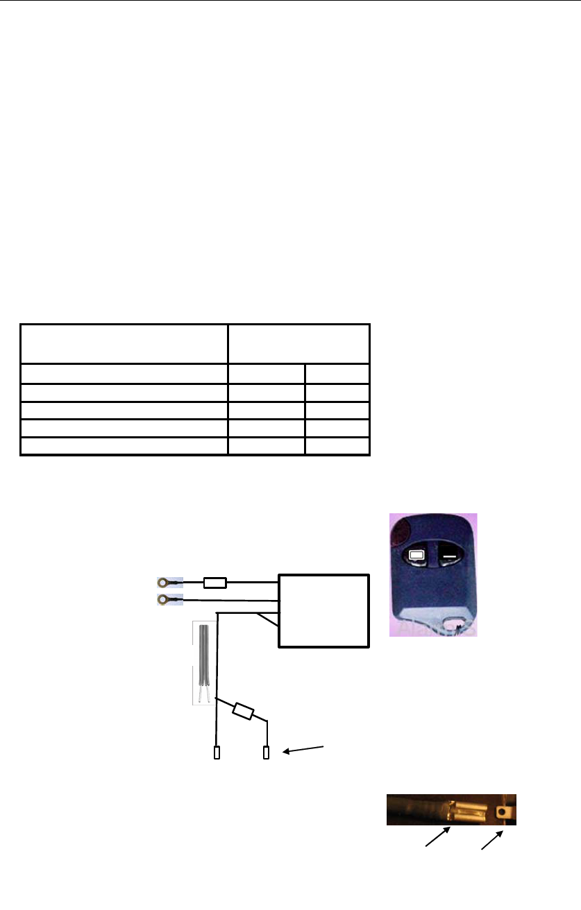
3 Receiver leads
6mm ring terminal +
6mm ring terminal -
Terminal
Mating Tab
Altec Products Inc.
14050 Lincoln St. NE, Ham Lake MN 55304
Phone 763 785 9035 www.altecproducts.com
Fax 763 785 9084
5 A Fuse
Battery Input Leads:
120 cm (47") inch
leads to battery
Output leads to motor:
150 cm (59") lead length
20 Gage, two strand wire
Receiver
Red
Black
Transmitter Buttons
A B
Resister Button "A" is Up, wire "A" is + and "B" -
Bottom "B" Is DOWN, wire "A" is - and "B" +
A B
Black Black with
wire white
stripe
Wire Specifications:
All wire is 20 gage (8mm) or larger, two
conductor, 105 deg C rated, minimum
insulation thickness of .50mm (.020 inch)
Two Conductor
(See layout
for button
detail
)
two push-on terminal receptacles to
fit 2.79mm wide x 0.51mm thick x
5.4mm long tab on motor supplied by
Altec

Page 3 of 3
NOTE: The manufacturer is not responsible for any radio or TV interference
caused by unauthorized modifications to this equipment.Such modifications
could void the user’s authority to operate the equipment.
Federal Communications Commission (FCC) Statement
NOTE: This equipment has been tested and found to comply with the limits for
a Class B digital device, pursuant to Part 15 of the FCC Rules. These limits are
designed to provide reasonable protection against harmful interference in a
residential installation.
This equipment generates, uses and can radiate radio frequency energy and, if
not installed and used in accordance with the instructions, may cause harmful
interference to radio communications. However, there is no guarantee that
interference will not occur in a particular installation. If this equipment does
cause harmful interference to radio or television reception, which can be
determined by turning the equipment off and on, the user is encouraged to try
to correct the interference by one or more of the following measures:
-- Reorient or relocate the receiving antenna.
-- Increase the separation between the equipment and receiver.
-- Connect the equipment into an outlet on a circuit different from that to which
the receiver is connected.
-- Consult the dealer or an experienced radio/TV technician for help.