GIGA BYTE TECHNOLOGY
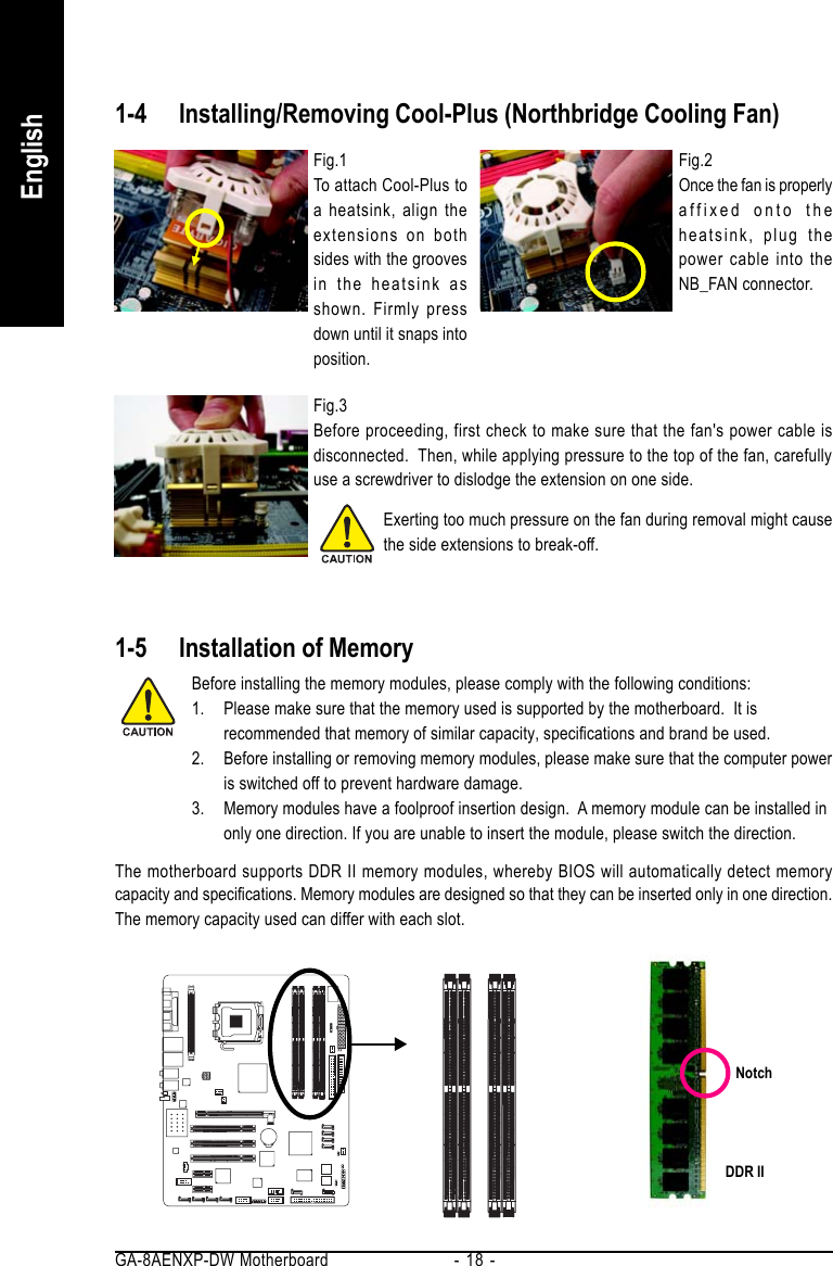
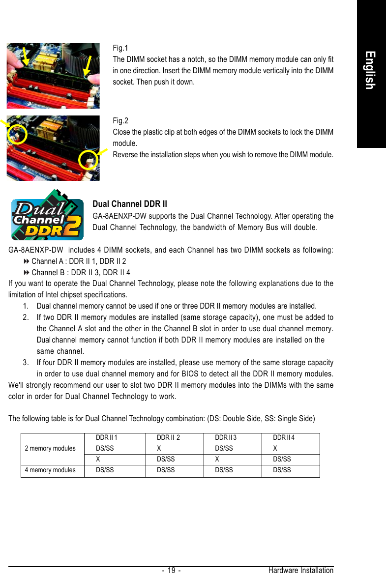
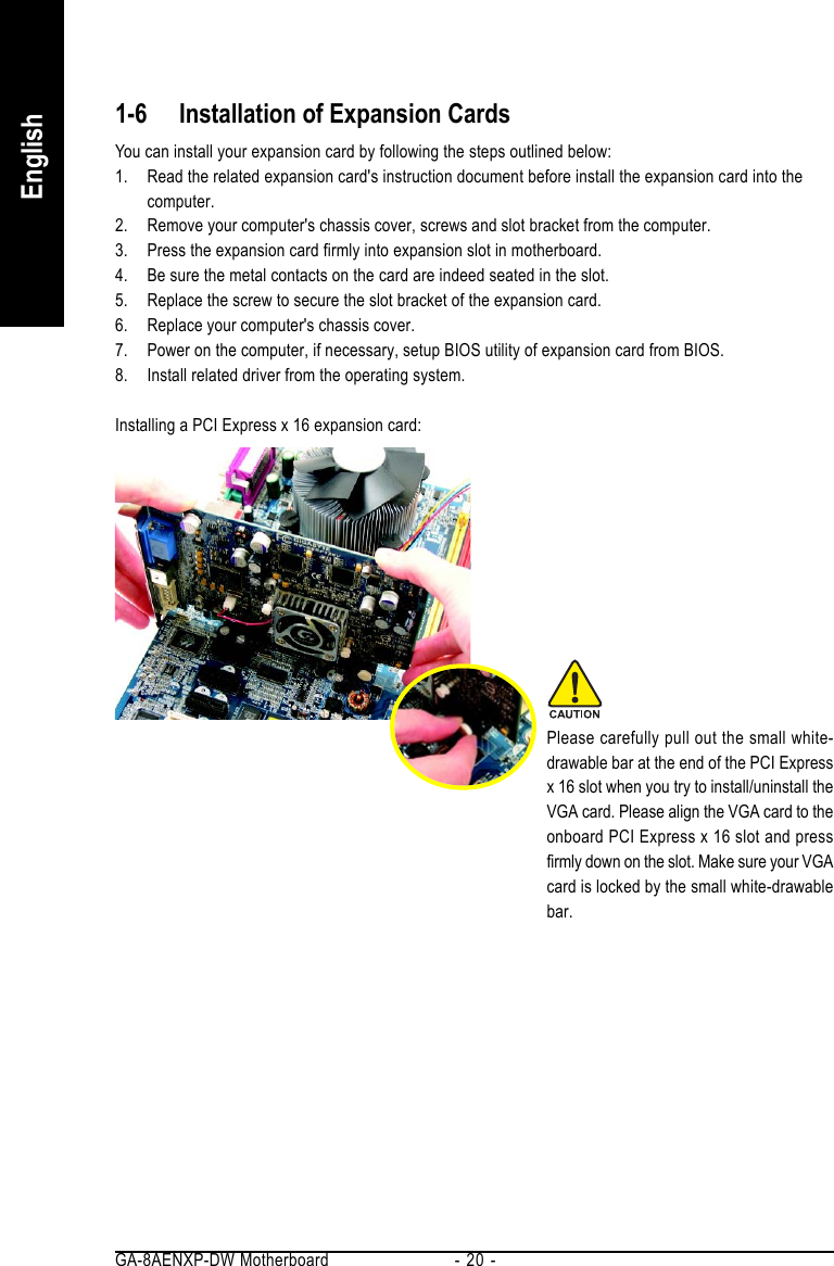
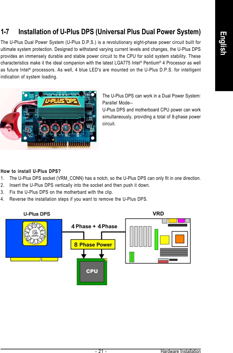
 GA-8AENXP-DW Wireless Lan Motherboard User Manual GA 8AENXP DW UserMan

GIGA-BYTE TECHNOLOGY CO., LTD. Wireless Lan Motherboard GA 8AENXP DW UserMan

Contents

Users Manual Part 1

GA-8AENXP-DWIntel® Pentium® 4 LGA775 Processor MotherboardUser's ManualRev. 100112ME-8AENXPDW-1001
MotherboardGA-8AENXP-DWJan. 15, 2005Jan. 15, 2005
Important Safety InformationRead and follow all instructions marked on the product and in the documentation before you operateyour system. Retain all safety and operating instructions for future use.1. The product should be operated only from the type of power source indicated on the rating label.2. If your computer has a voltage selector switch, make sure that the switch is in the proper positionfor your area. The voltage selector switch is set at the factory to the correct voltage.3. The plug-socket combination must be accessible at all times because it serves as the maindisconnecting device.4. All product shipped with a three-wire electrical grounding-type plug only fits into a grounding-typepower outlet. This is a safety feature. The equipment grounding should be in accordance with localand national electrical codes. The equipment operates safely when it is used in accordance with itsmarked electrical ratings and product usage instructions.5. Use only the power cord and batteries indicated in this manual. Do not dispose of batteries in a fire.They may explode. Check with codes for possible special disposal instructions.6. Do not use this product near water or a heat source.7. Set up the product on a stable work surface or so as to ensure stability of the system.8. Openings in the case are provided for ventilation. Do not block or cover these openings. Makesure you provide adequate space around the system for ventilation when you set up your workarea. Never insert objects of any kind into the ventilation openings.9. To avoid electrical shock, always unplug all power cables and modem cables from the wall outletsbefore removing covers.10. Allow the product to cool before removing covers or touching internal components.Battery safety information1. The lithium battery on the system board of the computer contains lithium and can explode if notproperly used, handled, or disposed of. Do not: (1) throw or immerse into water, (2) heat to morethan 100 deg C (212 deg F), or (3) repair or disassemble.2. Dispose of it as required by local ordinances or regulations.Radio equipment safety information1. Keep the radio components at least 20 cm from a pacemaker, as otherwise the proper operation ofthe pacemaker may be impaired by radio waves.2. The transmitted radio waves can cause an unpleasant humming in hearing aids.3. Do not let the radio components work near flammable gases or into hazardous environments (e.g.paintshops), as the transmitted radio waves can cause an explosion or a fire.
Federal Communications Commission (FCC) StatementThis device complies with Part 15 of the FCC Rules. Operation is subject to the following twoconditions:(1) this device may not cause harmful interference, and(2) this device must accept any interference received, including interference that may cause undesiredoperation.This equipment has been tested and found to comply with the limits for a Class B digital device,pursuant to Part 15 of the FCC Rules. These limits are designed to provide reasonable protectionagainst harmful interference in a residential installation. This equipment generates, uses, and can radiateradio frequency energy and, if not installed and used in accordance with the instructions, may causeharmful interference to radio communications. However, there is no guarantee that interference will notoccur in a particular installation. If this equipment does cause harmful interference to radio or televisionreception, which can be determined by turning the equipment off and on, the user is encouraged to tryto correct the interference by one or more of the following measures:xxxxxReorient or relocate the receiving antenna.xxxxxIncrease the separation between the equipment and receiver.xxxxxConnect the equipment into an outlet on a circuit different from that to which thereceiver is connected.xxxxxConsult a dealer or experienced TV/radio technician for help.Properly shielded and grounded cables and connectors must be used in order to meet FCC emissionlimits. Neither the Dealer nor the Manufacturer are responsible for any radio or television interferencecaused by using other than recommended cables and connectors or by unauthorized changes ormodifications to this equipment. Unauthorized changes or modifications could void the user's authorityto operate the equipment.Canadian Department of Communications Compliance StatementThis digital apparatus does not exceed the Class B limits for radio noise emissions from digitalapparatus as set out in the radio interference regulations of Industry Canada.Le present appareil numerique n'emet pas de bruits radioelectriques depassant les limites applicablesaux appareils numeriques de Classe B prescrites dans le reglement sur le brouillage radioelectriqueedicte par Industrie Canada.
European Community Directive Conformance Statement: R&TTE DirectiveThis wireless LAN card has been approved in accordance with Council Decision 99/5/EC on radioequipment and terminal telecommunication equipment (R&TTE Directive 1999/5/EC) as per* EN 60950 Safety of Information Technology equipment* EN 300 328 Technical requirements for radio equipment* EN 301 489 EMC requirements for radio equipmentThis equipment is is suitable for is suitable for use in all the European Community Member States.Contact the corresponding government office of the respective country for current information onpossible operating restrictions. If your country is not included in the list, then please contact thecorresponding supervisory authority as to whether the use of this product is permitted in your country.
Copyright© 2005 GIGA-BYTE TECHNOLOGY CO., LTD. All rights reserved.The trademarks mentioned in the manual are legally registered to their respective companies.NoticeThe written content provided with this product is the property of Gigabyte.No part of this manual may be reproduced, copied, translated, or transmitted in any form or by anymeans without Gigabyte's prior written permission. Specifications and features are subject tochange without prior notice.Product Manual ClassificationIn order to assist in the use of this product, Gigabyte has categorized the user manual in thefollowing:For quick installation, please refer to the "Hardware Installation Guide" included with theproduct.For detailed product information and specifications, please carefully read the "Product User Manual".For detailed information related to Gigabyte's unique features, please go to Gigabyte'swebsite under "Technology Guide" where information can be downloaded in .pdf format.For more product details, please click onto Gigabyte's website at www.gigabyte.com.tw
- 7 -Table of ContentsImportant Safety Information ........................................................................................... 3GA-8AENXP-DW Motherboard Layout .......................................................................... 9Block Diagram .............................................................................................................. 10Chapter 1 Hardware Installation .................................................................................. 131-1 Considerations Prior to Installation .................................................................. 131-2 Feature Summary .......................................................................................... 141-3 Installation of the CPU and Heatsink .............................................................. 161-3-1 Installation of the CPU ......................................................................................... 161-3-2 Installation of the Heatsink .................................................................................. 171-4 Installing/Removing Cool-Plus (Northbridge Cooling Fan) .............................. 181-5 Installation of Memory .................................................................................... 181-6 Installation of Expansion Cards ...................................................................... 201-7 Installation of U-Plus DPS (Universal Plus Dual Power System) ................. 211-8 I/O Back Panel Introduction ........................................................................... 221-9 Connectors Introduction .................................................................................. 23Chapter 2  BIOS Setup................................................................................................ 35The Main Menu (For example: BIOS Ver. : F1) ....................................................... 362-1 Standard CMOS Features ............................................................................. 382-2 Advanced BIOS Features .............................................................................. 402-3 Integrated Peripherals ..................................................................................... 422-4 Power Management Setup ............................................................................. 462-5 PnP/PCI Configurations ................................................................................. 472-6 PC Health Status ........................................................................................... 482-7 MB Intelligent Tweaker(M.I.T.) ....................................................................... 502-8 Select Language ............................................................................................. 522-9 Load Fail-Safe Defaults ................................................................................... 522-10 Load Optimized Defaults ................................................................................. 532-11 Set Supervisor/User Password ..................................................................... 532-12 Save & Exit Setup ......................................................................................... 542-13 Exit Without Saving ....................................................................................... 54
- 8 -Chapter 3 Drivers Installation ...................................................................................... 553-1 Install Chipset Drivers .................................................................................... 553-2 Software Applications ..................................................................................... 563-3 Driver CD Information .................................................................................... 563-4 Hardware Information ..................................................................................... 573-5 Contact Us ..................................................................................................... 57Chapter 4  Appendix ................................................................................................... 594-1 Unique Software Utilities ................................................................................ 594-1-1 EasyTune 5 Introduction ..................................................................................... 604-1-2 Xpress Recovery Introduction ........................................................................... 614-1-3 Flash BIOS Method Introduction ........................................................................ 644-1-4 Serial ATA BIOS Setting Utility Introduction ...................................................... 754-1-5 Configuring the Onboard Wireless LAN ............................................................ 874-1-6 2- / 4- / 6- / 8- Channel Audio Function Introduction ...................................... 894-2 Troubleshooting ............................................................................................... 94
- 9 -GA-8AENXP-DW Motherboard LayoutATX_12VCPU_FANVRM_CONNIntel 925XPCIE_16NB_FANCODECIRIT8712FSATA3_SBSATA2_SBSATA0_SIIIntel ICH6RSiI3114MainBIOSBackupBIOSPCIE_1PCIE_2PCI1PCI2F1_1394F2_1394F_USB2F_USB1SATA1_SBSATA0_SBTSB82AA2TSB81BA3 PDC 20779BATPWR_FANATXIDE1FDDCLR_CMOSSYS_FANSATA1_SIISATA2_SIISATA3_SIIGA-8AENXP-DWMSLGA775AUDIO1SPDIF_ILPTUSBLAN2USBLAN1AZALIA_FPCD_INSPDIF_OAUDIO2F_PANELPWR_LEDKBPCI3Marvell8053WDSIWSMASATA0_PR SATA1_PRMarvell8053CIIDE2Atheros WLANCOMADDRII1DDRII2DDRII3DDRII4
- 10 -Block Diagram(Note) To use a DDRII 711 memory module on the motherboard, you must install an 1066MHz FSBprocessor and overclock in BIOS. To use a DDRII 600 memory module on the motherboard,you must install an 800MHz FSB processor and overclock in BIOS.Line-OutMICLGA775ProcessorCPUCLK+/-(266/200/133MHz)PCI Express x1633MHzHostInterfaceIntel925XMCH MCHCLK (266/200/133MHz)66MHz48MHzDDRII 711/600/533/400MHz(Note)DIMM24MHz33MHzIT 8712FATA33/66/100 IDEChannelIntelICH6R14.318MHzDual BIOSCODECLine-InPCICLK(33MHz)3 PCIPCI Bus3 IEEE1394bSPDIF InSPDIF Out2 PCI Express x 1 PortsPCI Express x 1 Bus8 USBPortsDual Channel MemoryFloppyPS/2 KB/MouseLPT PortCOM PortTSB82AA2TSB81BA3SiI3114Side Speaker OutCenter/Subwoofer Speaker OutSurround Speaker OutPCI-ECLK(100MHz)PCI-ECLK(100MHz)Marvell8053RJ454 Serial ATAMarvell8053RJ454 Serial ATA2 Serial ATA IIPDC20779ATA33/66/100/133 IDE ChannelAtherosAR2414ASMA
- 11 -
- 12 -
Hardware Installation- 13 -English1-1 Considerations Prior to InstallationPreparing Your ComputerThe motherboard contains numerous delicate electronic circuits and components which canbecome damaged as a result of electrostatic discharge (ESD).  Thus, prior to installation, pleasefollow the instructions below:1. Please turn off the computer and unplug its power cord.2. When handling the motherboard, avoid touching any metal leads or connectors.3. It is best to wear an electrostatic discharge (ESD) cuff when handling electronic components(CPU, RAM).4. Prior to installing the electronic components, please have these items on top of an antistaticpad or within a electrostatic shielding container.5. Please verify that you the power supply is switched off before unplugging the power supplyconnector from the motherboard.Installation Notices1. Prior to installation, please do not remove the stickers on the motherboard.  These stickersare required for warranty validation.2. Prior to the installation of the motherboard or any hardware, please first carefully read theinformation in the provided manual.3. Before using the product, please verify that all cables and power connectors are connected.4. To prevent damage to the motherboard, please do not allow screws to come in contact withthe motherboard circuit or its components.5. Please make sure there are no leftover screws or metal components placed on the motherboardor within the computer casing.6. Please do not place the computer system on an uneven surface.7. Turning on the computer power during the installation process can lead to damage to systemcomponents as well as physical harm to the user.8. If you are uncertain about any installation steps or have a problem related to the use of theproduct, please consult a certified computer technician.Instances of Non-Warranty1. Damage due to natural disaster, accident or human cause.2. Damage as a result of violating the conditions recommended in the user manual.3. Damage due to improper installation.4. Damage due to use of uncertified components.5. Damage due to use exceeding the permitted parameters.6. Product determined to be an unofficial Gigabyte product.Chapter 1Hardware Installation
GA-8AENXP-DW Motherboard - 14 -EnglishCPU Supports the latest Intel® Pentium® 4 LGA775 CPUSupports 1066/800/533MHz FSBL2 cache varies with CPUChipset Northbridge: Intel® 925XE Express ChipsetSouthbridge: Intel® ICH6RMemory 4 DDR II DIMM memory slots (supports up to 4GB memory) (Note 1)Supports dual channel DDR II 711/600/533/400 unbuffered DIMM(Note 2)Supports 1.8V DDR II DIMMSlots 1 PCI Express x 16 slot2 PCI Express x 1 slots3 PCI slotsIDE Connections 1 port from ICH6R (IDE1) (UDMA 33/ATA 66/ATA 100), allows connection of2 IDE devices1 port from PDC20779 (IDE2)(UDMA 33/ATA 66/ATA 100/ATA 133), allowsconnection of 2 IDE hard drivesFDD Connections 1 FDD connection, allows connection of 2 FDD devicesOnboard SATA 4 SATA ports from ICH6R controller (SATA0_SB, SATA1_SB, SATA2_SB,SATA3_SB);4 SATA ports from SiI3114 controller (SATA0_SII, SATA1_SII, SATA2_SII,SATA3_SII)2 SATA II ports from PDC20779 controller (SATA0_PR, SATA1_PR)Peripherals 1 parallel port supporting Normal/EPP/ECP mode8 USB 2.0/1.1 ports (rear x 4, front x 4 via cable)3 IEEE1394b ports (requires cable)Onboard COMA connection1 front audio connector1 IR connector1 PS/2 keyboard port1 PS/2 mouse portOnboard LAN Onboard Marvell 8053 chip (10/100/1000 Mbit) (LAN1/LAN2)2 RJ45 portsOnboard Audio ALC880 CODECSupports Jack Sensing functionSupports 2 / 4 / 6 / 8 channel audioSupports Line In ; Line Out (Front Speaker Out) ; MIC ; Surround SpeakerOut (Rear Speaker Out) ; Center/Subwoofer Speaker Out ; Side SpeakerOut connectionSPDIF In/Out connectionCD In connection1-2 Feature Summary(Note 1) Due to standard PC architecture, a certain amount of memory is reserved for system usageand therefore the actual memory size is less than the stated amount. For example, 4 GB ofmemory size will instead be shown as 3.xxGB memory during system startup.(Note 2) To use a DDRII 711 memory module on the motherboard, you must install an 1066MHz FSBprocessor and overclock in BIOS. To use a DDRII 600 memory module on the motherboard,you must install an 800MHz FSB processor and overclock in BIOS.
Hardware Installation- 15 -EnglishI/O Control IT8712FHardware Monitor System voltage detectionCPU temperature detectionCPU / System / Power fan speed detectionCPU warning temperatureCPU / System / Power fan failure warningCPU smart fan controlOnboard SATA RAID Onboard ICH6R chipset (SATA0_SB, SATA1_SB, SATA2_SB, SATA3_SB)- supports data striping (RAID 0) or mirroring (RAID 1) function- supports data transfer rate of up to 150 MB/s- supports hot plugging function- supports a maximum of 4 SATA connections- supported on the Win 2000/XP operating systemsOnboard Silicon Image SiI3114 chipset (SATA0_SII, SATA1_SII, SATA2_SII, SATA3_SII)- supports data striping (RAID 0), mirroring (RAID 1) orstriping + mirroring (RAID 0+1)- supports data transfer rate of up to 150 MB/s- supports hot plugging function- supports a maximum of 4 SATA connections- supported on the Win 2000/XP/NT/98/Me operating systemsOnboard Promise PDC20779 chipset (SATA0_PR, SATA1_PR)- supports data striping (RAID 0), mirroring (RAID 1)- supports data transfer rate of up to 300 MB/s- supports hot plugging function- supports a maximum of 2 SATA II connections- supported on the Win 2000/XP operating systemsOnboard Wireless LAN supports IEEE 802.11b, 802.11g standards, Atheros Super G mode- up to 11Mbps/54Mbps/108Mbps wireless data transmission- frequency band: 2400 - 2483.5 MHz- Modulation technology: OFDM/DSSS- Modulation techniques: BPSK, QPSK, 16 QAM, 64 QAM, DBPSK,DQPSK, CCK- ouput level: 20dBm (maximum) @ antenna connectorBIOS Use of licensed AWARD BIOSSupports Dual BIOS/Q-FlashAdditional Features Supports U-Plus DPSSupports @BIOSSupports EasyTune 5 (Note)Overclocking Over Voltage via BIOS (CPU/ FSB/DDR II/ PCI-E)Over Clock via BIOS (CPU/ DDR II/ PCI-E)Form Factor ATX form factor; 30.5cm x 24.4cm(Note) EasyTune 5 functions may vary depending on different motherboards.
GA-8AENXP-DW Motherboard - 16 -English1-3 Installation of the CPU and HeatsinkBefore installing the CPU, please comply with the following conditions:1. Please make sure that the motherboard supports the CPU.2. Please take note of the one indented corner of the CPU.  If you install the CPU in the wrongdirection, the CPU will not insert properly.  If this occurs, please change the insert directionof the CPU.3. Please add an even layer of heat sink paste between the CPU and heatsink.4. Please make sure the heatsink is installed on the CPU prior to system use, otherwiseoverheating and permanent damage of the CPU may occur.5. Please set the CPU host frequency in accordance with the processor specifications.  It is notrecommended that the system bus frequency be set beyond hardware specifications since itdoes not meet the required standards for the peripherals.  If you wish to set the frequencybeyond the proper specifications, please do so according to your hardware specificationsincluding the CPU, graphics card, memory, hard drive, etc.HT functionality requirement content :Enabling the functionality of Hyper-Threading Technology for your computer system requires allof the following platform components:- CPU: An Intel® Pentium 4 Processor with HT Technology- Chipset: An Intel® Chipset that supports HT Technology- BIOS: A BIOS that supports HT Technology and has it enabled- OS: An operation system that has optimizations for HT Technology1-3-1 Installation of the CPUFig. 1Gently lift the metallever located on theCPU socket to theupright position.Metal Lever Fig. 2Remove the plasticcovering on the CPUsocket.Fig. 4Once the CPU isproperly inserted,please replace theplastic covering andpush the metal leverback into its originalposition.Fig. 3Notice the small goldcolored triangle locatedon the edge of the CPUsocket.  Align theindented corner of theCPU with the triangle and gently insert the CPU intoposition. (Grasping the CPU firmly between yourthumb and forefinger, carefully place it into the socketin a straight and downwards motion. Avoid twisting orbending motions that might cause damage to the CPUduring installation.)
Hardware Installation- 17 -English1-3-2 Installation of the HeatsinkFig.1Please apply an even layer of heatsink paste onthe surface of the installed CPU.The heatsink may adhere to the CPU as a result of hardening of the heatsink paste. To preventsuch an occurrence, it is suggested that either thermal tape rather than heat sink paste be used forheat dissipation or using extreme care when removing the heatsink.Fig. 6Finally, please attach the power connector of theheatsink to the CPU fan header located on themotherboard.Fig. 3Place the heatsink atop the CPU and make surethe push pins aim to the pin hole on themotherboard. Pressing down the push pinsdiagonally.Fig. 2(Turning the push pin along the direction of arrow isto remove the heatsink, on the contrary, is to install.)Please note the direction of arrow sign on the malepush pin doesn't face inwards before installation. (Thisinstruction is only for Intel boxed fan)Fig. 4Please make sure the Male and Female push pin arejoined closely. (for detailed installation instructions,please refer to the heatsink installation section of theuser manual)Male Push PinFemale Push PinThe top of Female Push PinFig. 5Please check the back of motherboard afterinstalling. If the push pin is inserted as the picture,the installation is complete.
GA-8AENXP-DW Motherboard - 18 -EnglishBefore installing the memory modules, please comply with the following conditions:1. Please make sure that the memory used is supported by the motherboard.  It isrecommended that memory of similar capacity, specifications and brand be used.2. Before installing or removing memory modules, please make sure that the computer poweris switched off to prevent hardware damage.3. Memory modules have a foolproof insertion design.  A memory module can be installed inonly one direction. If you are unable to insert the module, please switch the direction.NotchDDR II1-5 Installation of MemoryThe motherboard supports DDR II memory modules, whereby BIOS will automatically detect memorycapacity and specifications. Memory modules are designed so that they can be inserted only in one direction.The memory capacity used can differ with each slot.1-4 Installing/Removing Cool-Plus (Northbridge Cooling Fan)Fig.1To attach Cool-Plus toa heatsink, align theextensions on bothsides with the groovesin the heatsink asshown. Firmly pressdown until it snaps intoposition.Fig.2Once the fan is properlyaffixed onto theheatsink, plug thepower cable into theNB_FAN connector.Fig.3Before proceeding, first check to make sure that the fan's power cable isdisconnected.  Then, while applying pressure to the top of the fan, carefullyuse a screwdriver to dislodge the extension on one side.Exerting too much pressure on the fan during removal might causethe side extensions to break-off.
Hardware Installation- 19 -EnglishFig.1The DIMM socket has a notch, so the DIMM memory module can only fitin one direction. Insert the DIMM memory module vertically into the DIMMsocket. Then push it down.Fig.2Close the plastic clip at both edges of the DIMM sockets to lock the DIMMmodule.Reverse the installation steps when you wish to remove the DIMM module.Dual Channel DDR IIGA-8AENXP-DW supports the Dual Channel Technology. After operating theDual Channel Technology, the bandwidth of Memory Bus will double.GA-8AENXP-DW  includes 4 DIMM sockets, and each Channel has two DIMM sockets as following:Channel A : DDR II 1, DDR II 2Channel B : DDR II 3, DDR II 4If you want to operate the Dual Channel Technology, please note the following explanations due to thelimitation of Intel chipset specifications.1. Dual channel memory cannot be used if one or three DDR II memory modules are installed.2. If two DDR II memory modules are installed (same storage capacity), one must be added tothe Channel A slot and the other in the Channel B slot in order to use dual channel memory.Dualchannel memory cannot function if both DDR II memory modules are installed on thesame channel.3. If four DDR II memory modules are installed, please use memory of the same storage capacityin order to use dual channel memory and for BIOS to detect all the DDR II memory modules.We'll strongly recommend our user to slot two DDR II memory modules into the DIMMs with the samecolor in order for Dual Channel Technology to work.The following table is for Dual Channel Technology combination: (DS: Double Side, SS: Single Side)2 memory modules4 memory modulesDDR II 1 DDR II  2 DDR II 3 DDR II 4DS/SS X DS/SS XX DS/SS X DS/SSDS/SS DS/SS DS/SS DS/SS
GA-8AENXP-DW Motherboard - 20 -English1-6 Installation of Expansion CardsYou can install your expansion card by following the steps outlined below:1. Read the related expansion card's instruction document before install the expansion card into thecomputer.2. Remove your computer's chassis cover, screws and slot bracket from the computer.3. Press the expansion card firmly into expansion slot in motherboard.4. Be sure the metal contacts on the card are indeed seated in the slot.5. Replace the screw to secure the slot bracket of the expansion card.6. Replace your computer's chassis cover.7. Power on the computer, if necessary, setup BIOS utility of expansion card from BIOS.8. Install related driver from the operating system.Installing a PCI Express x 16 expansion card:Please carefully pull out the small white-drawable bar at the end of the PCI Expressx 16 slot when you try to install/uninstall theVGA card. Please align the VGA card to theonboard PCI Express x 16 slot and pressfirmly down on the slot. Make sure your VGAcard is locked by the small white-drawablebar.
Hardware Installation- 21 -English1-7 Installation of U-Plus DPS (Universal Plus Dual Power System)The U-Plus Dual Power System (U-Plus D.P.S.) is a revolutionary eight-phase power circuit built forultimate system protection. Designed to withstand varying current levels and changes, the U-Plus DPSprovides an immensely durable and stable power circuit to the CPU for solid system stability. Thesecharacteristics make it the ideal companion with the latest LGA775 Intel® Pentium® 4 Processor as wellas future Intel® processors. As well, 4 blue LED's are mounted on the U-Plus D.P.S. for intelligentindication of system loading.The U-Plus DPS can work in a Dual Power System:Parallel Mode--U-Plus DPS and motherboard CPU power can worksimultaneously, providing a total of 8-phase powercircuit.How to install U-Plus DPS?1. The U-Plus DPS socket (VRM_CONN) has a notch, so the U-Plus DPS can only fit in one direction.2. Insert the U-Plus DPS vertically into the socket and then push it down.3. Fix the U-Plus DPS on the motherbard with the clip.4. Reverse the installation steps if you want to remove the U-Plus DPS.
GA-8AENXP-DW Motherboard - 22 -English1-8 I/O Back Panel IntroductionPS/2 Keyboard and PS/2 Mouse ConnectorTo install a PS/2 port keyboard and mouse, plug the mouse to the left port (green) and the keyboard tothe right port (purple).Parallel PortThe parallel port allows connection of a printer, scanner and other peripheral devices.SPDIF_O (SPDIF Out)The SPDIF output is capable of providing digital audio to external speakers or compressed AC3data to an external Dolby Digital Decoder.SPDIF_I (SPDIF In)Use SPDIF In  feature only when your device has digital output function.LAN Port 1/LAN Port 2The provided Internet connection is Gigabit Ethernet (PCI Express Gigabit), providing data transferspeeds of 10/100/1000Mbps.USB portBefore you connect your device(s) into USB connector(s), please make sure your device(s) suchas USB keyboard, mouse, scanner, zip, speaker...etc. have a standard USB interface. Also makesure your OS supports USB controller. If your OS does not support USB controller, please contactOS vendor for possible patch or driver upgrade. For more information please contact your OS ordevice(s) vendors.Line InDevices like CD-ROM, walkman etc. can be connected to Line In jack.Line Out (Front Speaker Out)Connect the stereo speakers, earphone or front surround speakers to this connector.MIC InMicrophone can be connected to MIC In jack.Rear Speaker OutConnect the rear surround speakers to this connector.Center/Subwoofer Speaker OutConnect the Center/Subwoofer speakers to this connector.Side Speaker OutConnect the side surround speakers to this connector.
Hardware Installation- 23 -English1-9 Connectors IntroductionYou can use audio software to configure 2-/4-/6-/8-channel audio functioning.WDSI (Wireless LAN LED)Indicate the data activity status with the onboard wireless LAN . The led blinks every few secondswhen the onboardwireless LAN is on but has no data receiving/transimtting activity. The led staysoff when the onboard wireless LAN is off. The led blinks quickly when the onboard wireless LANis receiving/transmitting data.WSMA (Wireless LAN Antenna Port)Connect the dipolar antenna for the onboard wireless LAN.1) ATX_12V2) ATX (Power Connector)3) CPU_FAN4) SYS_FAN5) PWR_FAN6) NB_FAN7) FDD8) IDE1/IDE29) SATA0_SB/SATA1_SB/SATA2_SB/SATA3_SB10) SATA0_SII/SATA1_SII/SATA2_SII/SATA3_SII11) SATA0_PR/SATA1_PR12) PWR_LED13) COMA14) F_PANEL15) AZALIA_FP16) CD_IN17) F_USB1 / F_USB218) F1_1394 / F2_139419) IR20) CLR_CMOS21) CI22) BAT1347171862589121516201910 14112221813
GA-8AENXP-DW Motherboard - 24 -English1/2) ATX_12V/ATX (Power Connector)With the use of the power connector, the power supply can supply enough stable power to all thecomponents on the motherboard. Before connecting the power connector, please make sure that allcomponents and devices are properly installed.  Align the power connector with its proper location onthe motherboard and connect tightly.The ATX_12V power connector mainly supplies power to the CPU. If the ATX_12V power connectoris not connected, the system will not start.Caution!Please use a power supply that is able to handle the system voltage requirements.  It isrecommended that a power supply that can withstand high power consumption be used (300W orgreater).  If a power supply is used that does not provide the required power, the result can lead to anunstable system or a system that is unable to start.Please remove the small cover on the motherboard before plugging in while the ATX powersupplier is 24 pins; Otherwise, please do not remove it.Pin No. Definition1GND2GND3 +12V4 +12VPin No. Definition13.3V23.3V3GND4VCC5GND6VCC7GND8 Power Good9 5V SB(stand by +5V)10 +12V11 +12V12  3.3V(Only for 24pins ATX)13 3.3V14 -12V15 GND16 PS_ON(soft On/Off)17 GND18 GND19 GND20 -5V21 VCC22 VCC23 VCC24 GND13242413121
Hardware Installation- 25 -English3/4/5) CPU_FAN / SYS_FAN / PWR_FAN (Cooler Fan Power Connector)The cooler fan power connector supplies a +12V power voltage via a 3-pin/4-pin(only for CPU_FAN)power connector and possesses a ful-proof connection design.Most coolers are designed with color-coded power connector wires. A red power connector wireindicates a positive connection and requires a +12V power voltage. The black connector wire is theground wire (GND).Please remember to connect the power to the cooler to prevent system overheating and failure.Caution!Please remember to connect the power to the CPU fan to prevent CPU overheating and failure.6)  NB_FAN (Chip Fan Connector)If you installed wrong direction, the chip fan will not work. Sometimes will damage the chip fan.(Usually black cable is GND)Pin No. Definition1 +12V2GNDPin No. Definition1GND2 +12V3 Sense4 Speed Control(Only for CPU_FAN)1CPU_FANPWR_FAN11SYS_FAN1
GA-8AENXP-DW Motherboard - 26 -English7) FDD (FDD Connector)The FDD connector is used to connect the FDD cable while the other end of the cable connects to theFDD drive. The types of FDD drives supported are: 360KB, 720KB, 1.2MB, 1.44MB and 2.88MB.Please connect the red power connector wire to the pin1 position.8) IDE1/2 (IDE Connector)An IDE device connects to the computer via an IDE connector. One IDE connector can connect to oneIDE cable, and the single IDE cable can then connect to two IDE devices (hard drive or optical drive). Ifyou wish to connect two IDE devices, please set the jumper on one IDE device as Master and the otheras Slave (for information on settings, please refer to the instructions located on the IDE device).123334123940123940
Hardware Installation- 27 -English9) SATA0_SB/SATA1_SB/SATA2_SB/SATA3_SB (Serial ATA Connector, Controlled by ICH6R)10) SATA0_SII/SATA1_SII/SATA2_SII/SATA3_SII (Serial ATA Connector, Controlled by SiI3114)Serial ATA can provide 150MB/s transfer rate. Please refer to the BIOS setting for the Serial ATAand install the proper driver in order to work properly.Pin No. Definition1GND2TXP3TXN4GND5RXN6RXP7GND17SATA_SB(Controlled by ICH6R)SATA_SII(Controlled by SiI3114)11) SATA0_PR/SATA1_PR (Serial ATA II Connector, Controlled by PDC20779)Serial ATA II can provide 300MB/s transfer rate. Please refer to the BIOS setting for the Serial ATAII and install the proper driver in order to work properly.Pin No. Definition1GND2TXP3TXN4GND5RXN6RXP7GND17SATA_PR(Controlled by PDC20779)17
GA-8AENXP-DW Motherboard - 28 -English12) PWR_LEDPWR_LED is connect with the system power indicator to indicate whether the system is on/off. Itwill blink when the system enters suspend mode.Pin No. Definition1MPD+2MPD-3MPD-113) COMA (COMA Connector)Be careful with the polarity of the COMA connector. Check the pin assignments while you connectthe COMB cable. Please contact your nearest dealer for optional COMA cable.Pin No. Definition1 NDCDA-2NSINA3NSOUTA4 NDTRA-5GND6 NDSRA-7 NRTSA-8 NCTSA-9 NRIA-10 No Pin21109
GA-8AENXP-DW Motherboard - 29 -English14)  F_PANEL (Front Panel Jumper)Please connect the power LED, PC peaker, reset switch and power switch etc of your chassisfrontpanel to the F_PANEL connector according to the pin assignment below.HD (IDE Hard Disk Active LED) Pin 1: LED anode(+)(Blue) Pin 2: LED cathode(-)SPEAK (Speaker Connector) Pin 1: VCC(+)(Amber) Pin 2- Pin 3: NCPin 4: Data(-)RES (Reset Switch) Open: Normal Operation(Green) Close: Reset Hardware SystemPW (Power Switch) Open: Normal Operation(Red) Close: Power On/OffMSG (Message LED/Power/Sleep LED) Pin 1: LED anode(+)(Yellow) Pin 2: LED cathode(-)NC (Purple) NC121920HD-HD+RES+RES-NCSPEAK-MSG-MSG+PW-PW+SPEAK+Message LED/Power/Sleep LEDPower SwitchSpeaker ConnectorIDE Hard DiskActive LEDReset Switch
Hardware Installation- 30 -English16) CD_IN (CD In Connector)Connect CD-ROM or DVD-ROM audio out to the connector.Pin No. Definition1 CD-L2GND3GND4 CD-R15) AZALIA_FP (Front Audio Panel Connector)This connector is supported to connect HD(High Definition) Audio and AC'97 Audio. Check the pinassignment carefully while you connect the audio panel cable, incorrect connection between the cableand connector will make the device unable to work or even damage it. For optional audio panel cable,please contact your local dealer.12910Pin No. Definition1 MIC2_L2GND3 MIC2_R4-ACZ_DET5 Line2_R6 FSENSE17 FAUOIO_JD8No Pin9 LINE2_L10 FSENSE2Pin No. Definition1MIC2GND3MIC Power4N/A5 Line Out (R)6N/A7N/A8No Pin9 Line Out (L)10 N/AHD Audio: AC'97 Audio:HD Audio is the default setting for this connector. To enable AC'97 Audio, from BIOS settings,set Front Panel Type under Integrated Peripherals to AC97.1

Navigation menu