GIGA BYTE TECHNOLOGY GA-8AENXP-DW Wireless Lan Motherboard User Manual GA 8AENXP DW UserMan
GIGA-BYTE TECHNOLOGY CO., LTD. Wireless Lan Motherboard GA 8AENXP DW UserMan
UserManual.wiki
>
GIGA BYTE TECHNOLOGY
>
GA-8AENXP-DW User Manual
>
Users Manual Part 2
Contents
1.
Users Manual Part 1
2.
Users Manual Part 2
Users Manual Part 2
Navigation menu
Upload a User Manual
Namespaces
Wiki Guide
HTML
PDF
Info
Views
User Manual
Discussion / Help
Navigation

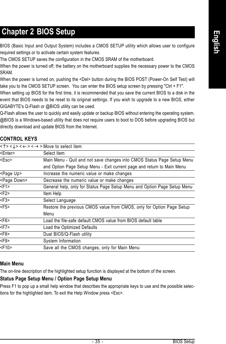
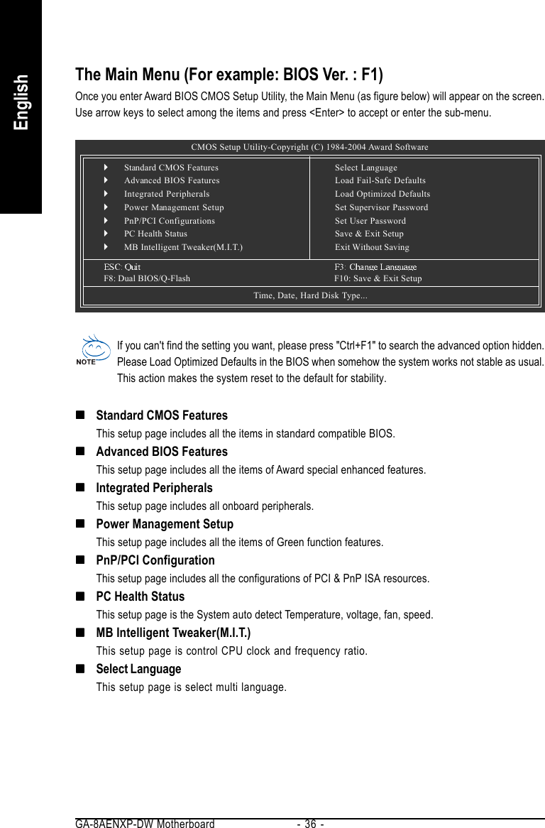
![GA-8AENXP-DW Motherboard - 38 -English2-1 Standard CMOS FeaturesDateThe date format is <week>, <month>, <day>, <year>.Week The week, from Sun to Sat, determined by the BIOS and is display onlyMonth The month, Jan. Through Dec.Day The day, from 1 to 31 (or the maximum allowed in the month)Year The year, from 1999 through 2098TimeThe times format in <hour> <minute> <second>. The time is calculated base on the 24-hour military-time clock. For example, 1 p.m. is 13:00:00.IDE Channel 0 Master, SlaveIDE HDD Auto-Detection Press "Enter" to select this option for automatic device detection.IDE Device Setup. You can use one of three methods:• Auto Allows BIOS to automatically detect IDE devices during POST(default)• None Select this if no IDE devices are used and the system will skip the automaticdetection step and allow for faster system start up.• Manual User can manually input the correct settings.Access Mode Use this to set the access mode for the hard drive. The four options are:CHS/LBA/Large/Auto(default:Auto)IDE Channel 2/3 Master, SlaveIDE HDD Auto-Detection Press "Enter" to select this option for automatic device detection.Extended IDE Drive. You can use one of two methods:• Auto Allows BIOS to automatically detect IDE devices during POST(default)• None Select this if no IDE devices are used and the system will skip the automaticdetection step and allow for faster system start up.Access Mode Use this to set the access mode for the hard drive. The two options are:Large/Auto(default:Auto)CMOS Setup Utility-Copyright (C) 1984-2004 Award SoftwareStandard CMOS FeaturesDate (mm:dd:yy) Wed, Oct 27 2004Time (hh:mm:ss) 22:31:24`IDE Channel 0 Master [None]`IDE Channel 0 Slave [None]`IDE Channel 2 Master [None]`IDE Channel 2 Slave [None]`IDE Channel 3 Master [None]`IDE Channel 3 Slave [None]Drive A [1.44M, 3.5"]Drive B [None]Floppy 3 Mode Support [Disabled]Halt On [All, But Keyboard]Base Memory 640KExtended Memory 511MTotal Memory 512MKLJI: Move Enter: Select +/-/PU/PD: Value F10: Save ESC: Exit F1: General HelpF3: Language F5: Previous Values F6: Fail-Safe Defaults F7: Optimized DefaultsItem HelpMenu Level`Change the day, month,year<Week>Sun. to Sat.<Month>Jan. to Dec.<Day>1 to 31 (or maximumallowed in the month)<Year>1999 to 2098](https://usermanual.wiki/GIGA-BYTE-TECHNOLOGY/GA-8AENXP-DW.Users-Manual-Part-2/User-Guide-517657-Page-8.png)
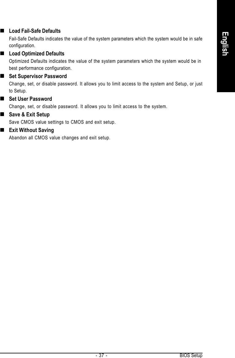
![GA-8AENXP-DW Motherboard - 40 -English2-2 Advanced BIOS FeaturesHard Disk Boot PrioritySelect boot sequence for onboard(or add-on cards) SCSI, RAID, etc.Use < > or < > to select a device, then press<+> to move it up, or <-> to move it down the list. Press<ESC> to exit this menu.First / Second / Third Boot DeviceFloppy Select your boot device priority by Floppy.LS120 Select your boot device priority by LS120.Hard Disk Select your boot device priority by Hard Disk.CDROM Select your boot device priority by CDROM.ZIP Select your boot device priority by ZIP.USB-FDD Select your boot device priority by USB-FDD.USB-ZIP Select your boot device priority by USB-ZIP.USB-CDROM Select your boot device priority by USB-CDROM.USB-HDD Select your boot device priority by USB-HDD.LAN Select your boot device priority by LAN.Disabled Select your boot device priority by Disabled." # " System will detect automatically and show up when you install the Intel® Pentium® 4processor with HT Technology.CMOS Setup Utility-Copyright (C) 1984-2004 Award SoftwareAdvanced BIOS Features`Hard Disk Boot Priority [Press Enter]First Boot Device [Floppy]Second Boot Device [Hard Disk]Third Boot Device [CDROM]ROM Boot Priority [SCSI]Password Check [Setup]# CPU Hyper-Threading [Enabled]Limit CPUID Max. to 3 [Enabled]No-Execute Memory Protect (Note) [Disabled]CPU Enhanced Halt (C1E) (Note) [Disabled]CPU Thermal Monitor 2(TM2) (Note) [Disabled]KLJI: Move Enter: Select +/-/PU/PD: Value F10: Save ESC: Exit F1: General HelpF3: Language F5: Previous Values F6: Fail-Safe Defaults F7: Optimized DefaultsItem HelpMenu Level`Select Hard Disk BootDevice Priority(Note) This item will show up when you install a processor that supports this function.](https://usermanual.wiki/GIGA-BYTE-TECHNOLOGY/GA-8AENXP-DW.Users-Manual-Part-2/User-Guide-517657-Page-10.png)
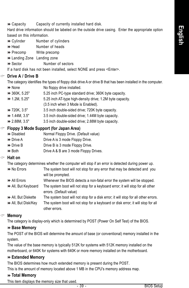
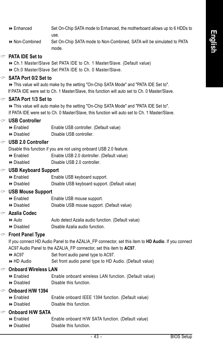
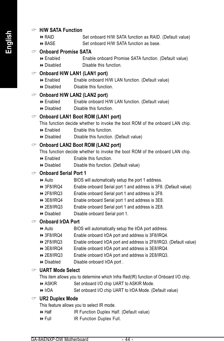
![GA-8AENXP-DW Motherboard - 42 -English2-3 Integrated PeripheralsOn-Chip Primary PCI IDEEnabled Enable onboard 1st channel IDE port. (Default value)Disabled Disable onboard 1st channel IDE port.SATA RAID / AHCI ModeRAID Select onboard Serial ATA function as RAID. (Default value)AHCI Support hotplug function under OS. WinXP, 2000 only.Disabled Select onboard Serial ATA function as ATA.On-Chip SATA ModeDisabled Disable this function.Auto BIOS will detect automatically. (Default value)Combined Set On-Chip SATA mode to Combined, you can use up to 4 HDDs on the motherboard;2 for SATA and the other for PATA IDE.CMOS Setup Utility-Copyright (C) 1984-2004 Award SoftwareIntegrated PeripheralsOn-Chip Primary PCI IDE [Enabled]SATA RAID/AHCI Mode [RAID]x On-Chip SATA Mode Autox PATA IDE Set to Ch.0 Master/SlaveSATA Port 0/2 Set to Ch.2 Master/SlaveSATA Port 1/3 Set to Ch.3 Master/SlaveUSB Controller [Enabled]USB 2.0 Controller [Enabled]USB Keyboard Support [Disabled]USB Mouse Support [Disabled]Azalia Codec [Auto]Front Panel Type [HD Audio]Onboard Wireless LAN [Enabled]Onboard H/W 1394 [Enabled]Onboard H/W SATA [Enabled]H/W SATA Function [RAID]Onboard Promise SATA [Enabled]Onboard H/W LAN1 [Enabled]Onboard H/W LAN2 [Enabled]KLJI: Move Enter: Select +/-/PU/PD: Value F10: Save ESC: Exit F1: General HelpF3: Language F5: Previous Values F6: Fail-Safe Defaults F7: Optimized DefaultsItem HelpMenu Level`If a hard diskcontroller card isused, set at Disabled.[Enabled]Enable on-chip IDEport.[Disabled]Disable on-chip IDEport.CMOS Setup Utility-Copyright (C) 1984-2004 Award SoftwareIntegrated PeripheralsKLJI: Move Enter: Select +/-/PU/PD: Value F10: Save ESC: Exit F1: General HelpF3: Language F5: Previous Values F6: Fail-Safe Defaults F7: Optimized DefaultsItem HelpMenu Level`Onboard LAN1 Boot ROM [Disabled]Onboard LAN2 Boot ROM [Disabled]Onboard Serial Port 1 [3F8/IRQ4]Onboard IrDA Port [2F8/IRQ3]UART Mode Select [IrDA]UR2 Duplex Mode [Half]Onboard Parallel Port [378/IRQ7]Parallel Port Mode [SPP]x ECP Mode Use DMA 3](https://usermanual.wiki/GIGA-BYTE-TECHNOLOGY/GA-8AENXP-DW.Users-Manual-Part-2/User-Guide-517657-Page-12.png)
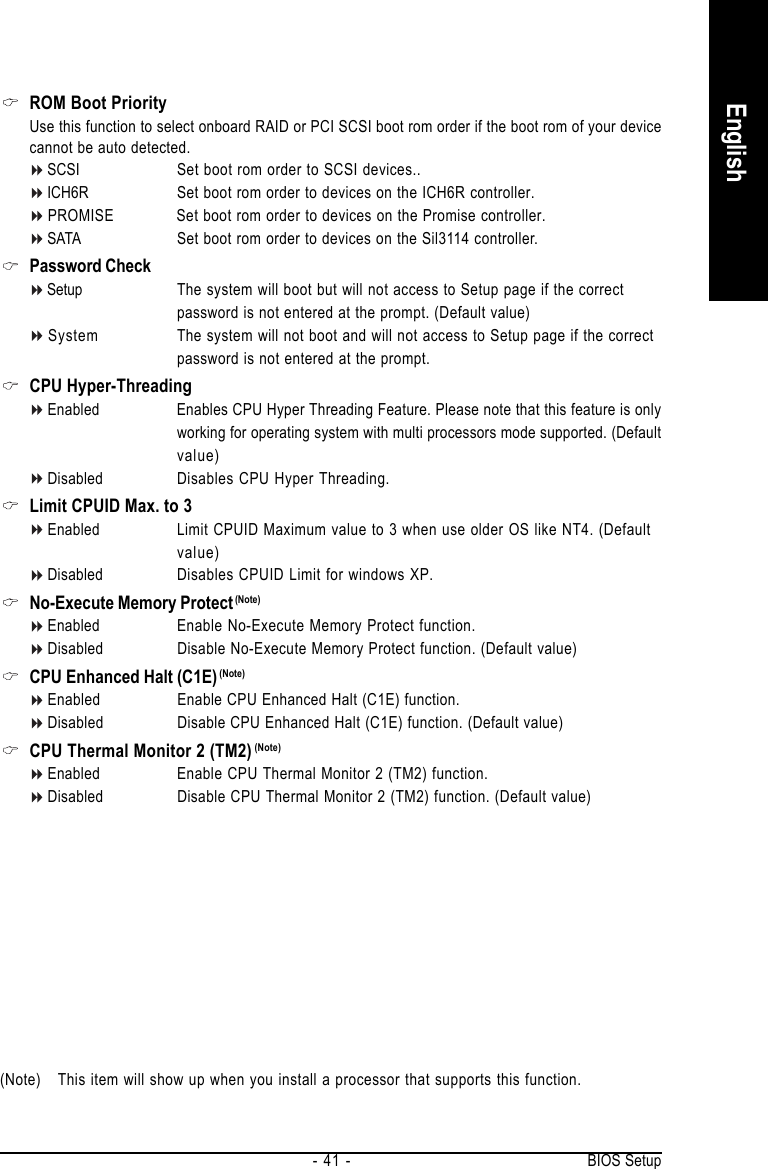
![GA-8AENXP-DW Motherboard - 46 -English2-4 Power Management SetupACPI Suspend TypeS1(POS) Set ACPI suspend type to S1/POS(Power On Suspend). (Default value)S3(STR) Set ACPI suspend type to S3/STR(Suspend To RAM).Soft-Off by PWR-BTTNInstant-Off Press power button then Power off instantly. (Default value)Delay 4 Sec. Press power button 4 seconds to Power off. Enter suspend if button is pressed lessthan 4 seconds.PME Event Wake UpDisabled Disable this function.Enabled Enable PME Event Wake up. (Default value)Power On by RingDisabled Disable Power on by Ring function.Enabled Enable Power on by Ring function. (Default value)Resume by AlarmYou can set "Resume by Alarm" item to enabled and key in Date/Time to power on system.Disabled Disable this function. (Default value)Enabled Enable alarm function to POWER ON system.If RTC Alarm Lead To Power On is Enabled.Date (of Month) Alarm : Everyday, 1~31Time (hh: mm: ss) Alarm : (0~23) : (0~59) : (0~59)Power On By MouseDisabled Disabled this function. (Default value)Double Click Double click on PS/2 mouse left button to power on the system.CMOS Setup Utility-Copyright (C) 1984-2004 Award SoftwarePower Management SetupACPI Suspend Type [S1(POS)]Soft-Off by PWR-BTTN [Instant-Off]PME Event Wake Up [Enabled]Power On by Ring [Enabled]Resume by Alarm [Disabled]x Date (of Month) Alarm Everydayx Time (hh:mm:ss) Alarm 0 : 0 : 0Power On By Mouse [Disabled]Power On By Keyboard [Disabled]x KB Power ON Password EnterAC BACK Function [Soft-Off]KLJI: Move Enter: Select +/-/PU/PD: Value F10: Save ESC: Exit F1: General HelpF3: Language F5: Previous Values F6: Fail-Safe Defaults F7: Optimized DefaultsItem HelpMenu Level`](https://usermanual.wiki/GIGA-BYTE-TECHNOLOGY/GA-8AENXP-DW.Users-Manual-Part-2/User-Guide-517657-Page-16.png)
![BIOS Setup- 47 -English2-5 PnP/PCI ConfigurationsPCI 1 IRQ AssignmentAuto Auto assign IRQ to PCI 1. (Default value)3,4,5,7,9,10,11,12,14,15 Set IRQ 3,4,5,7,9,10,11,12,14,15 to PCI 1.PCI 2 IRQ AssignmentAuto Auto assign IRQ to PCI 2. (Default value)3,4,5,7,9,10,11,12,14,15 Set IRQ 3,4,5,7,9,10,11,12,14,15 to PCI 2.PCI 3 IRQ AssignmentAuto Auto assign IRQ to PCI 3. (Default value)3,4,5,7,9,10,11,12,14,15 Set IRQ 3,4,5,7,9,10,11,12,14,15 to PCI 3.CMOS Setup Utility-Copyright (C) 1984-2004 Award SoftwarePnP/PCI ConfigurationsPCI 1 IRQ Assignment [Auto]PCI 2 IRQ Assignment [Auto]PCI 3 IRQ Assignment [Auto]KLJI: Move Enter: Select +/-/PU/PD: Value F10: Save ESC: Exit F1: General HelpF3: Language F5: Previous Values F6: Fail-Safe Defaults F7: Optimized DefaultsItem HelpMenu Level`Power On By KeyboardPassword Enter from 1 to 5 characters to set the Keyboard Power On Password.Disabled Disabled this function. (Default value)Keyboard 98 If your keyboard have "POWER Key" button, you can press the key to power onthe system.KB Power ON PasswordWhen "Power On by Keyboard" set at Password, you can set the password here.Enter Input password (from 1 to 5 characters) and press Enter to set the KeyboardPower On password.AC BACK FunctionSoft-Off When AC-power back to the system, the system will be in "Off" state.(Default value)Full-On When AC-power back to the system, the system always in "On" state.Memory When AC-power back to the system, the system will return to the Last statebefore AC-power off.](https://usermanual.wiki/GIGA-BYTE-TECHNOLOGY/GA-8AENXP-DW.Users-Manual-Part-2/User-Guide-517657-Page-17.png)
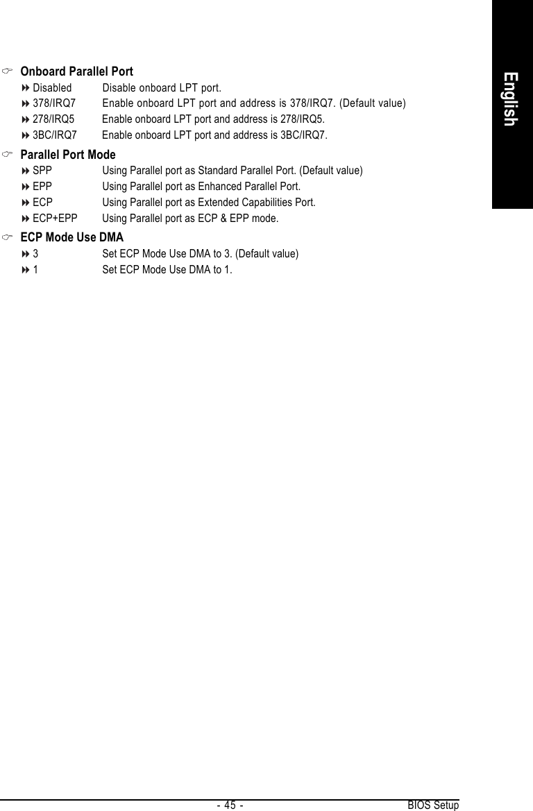
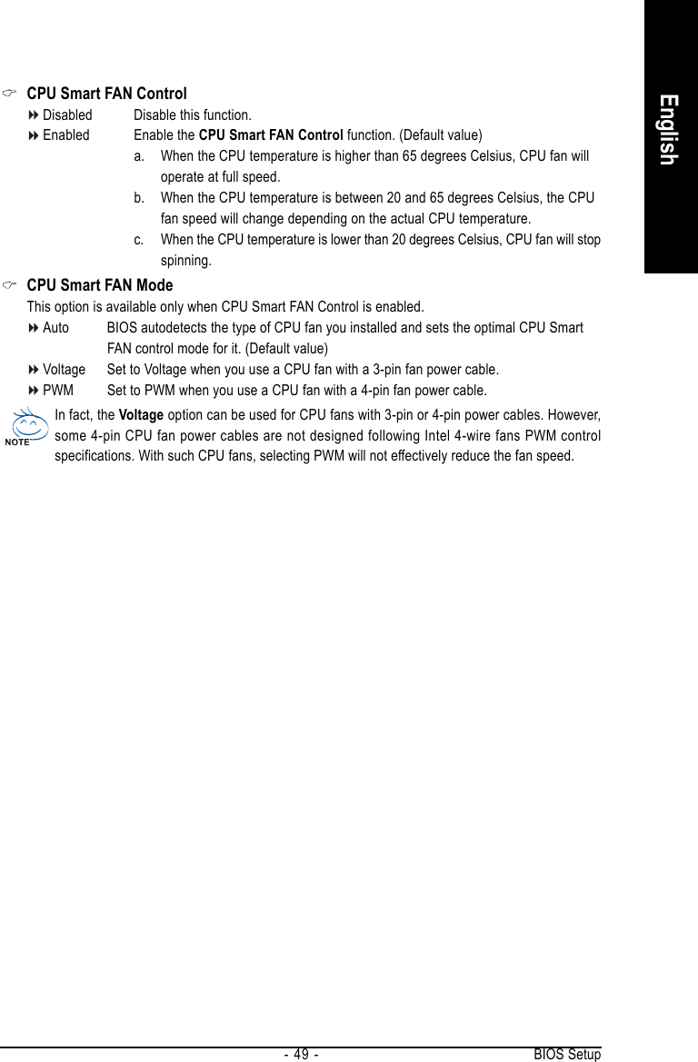
![GA-8AENXP-DW Motherboard - 48 -English2-6 PC Health StatusReset Case Open StatusDisabled Don't reset case open status. (Default value)Enabled Clear case open status at next boot.Case OpenedIf the case is closed, "Case Opened" will show "No". If the case has been opened, "Case Opened" willshow "Yes". If you want to reset "Case Opened" value, set "Reset Case Open Status" to Enabled thensave BIOS setup and restart your system.Current Voltage(V) Vcore / DDR18V / +3.3V / +12VDetect system's voltage status automatically.Current CPU TemperatureDetect CPU temperature automatically.Current CPU/POWER/SYSTEM FAN Speed (RPM)Detect CPU/POWER/SYSTEM fan speed status automatically.CPU Warning Temperature60oC / 140oF Monitor CPU temperature at 60oC / 140oF.70oC / 158oF Monitor CPU temperature at 70oC / 158oF.80oC / 176oF Monitor CPU temperature at 80oC / 176oF.90oC / 194oF Monitor CPU temperature at 90oC / 194oF.Disabled Disable this function. (Default value)CPU/POWER/SYSTEM FAN Fail WarningDisabled Fan warning function disable. (Default value)Enabled Fan warning function enable.CMOS Setup Utility-Copyright (C) 1984-2004 Award SoftwarePC Health StatusReset Case Open Status [Disabled]Case Opened NoVcore OKDDR18V OK+3.3V OK+12V OKCurrent CPU Temperature 33oCCurrent CPU FAN Speed 4687 RPMCurrent POWER FAN Speed 0 RPMCurrent SYSTEM FAN Speed 0 RPMCPU Warning Temperature [Disabled]CPU FAN Fail Warning [Disabled]POWER FAN Fail Warning [Disabled]SYSTEM FAN Fail Warning [Disabled]CPU Smart FAN Control [Enabled]CPU Smart FAN Mode [Auto]KLJI: Move Enter: Select +/-/PU/PD: Value F10: Save ESC: Exit F1: General HelpF3: Language F5: Previous Values F6: Fail-Safe Defaults F7: Optimized DefaultsItem HelpMenu Level`](https://usermanual.wiki/GIGA-BYTE-TECHNOLOGY/GA-8AENXP-DW.Users-Manual-Part-2/User-Guide-517657-Page-18.png)
![GA-8AENXP-DW Motherboard - 50 -English2-7 MB Intelligent Tweaker(M.I.T.)CMOS Setup Utility-Copyright (C) 1984-2004 Award SoftwareMB Intelligent Tweaker(M.I.T.)CPU Clock Ratio [15X]Robust Graphics Booster [Auto]C.I.A. 2 [Disabled]CPU Host Clock Control [Disabled]x CPU Host Frequency(Mhz) 200x PCI Express Frequency(Mhz) AutoMemory Frequency For [Auto]Memory Frequency (Mhz) 533DIMM OverVoltage Control [Normal]PCI-E OverVoltage Control [Normal]FSB OverVoltage Control [Normal]CPU Voltage Control [Normal]Normal CPU Vcore 1.3875VKLJI: Move Enter: Select +/-/PU/PD: Value F10: Save ESC: Exit F1: General HelpF3: Language F5: Previous Values F6: Fail-Safe Defaults F7: Optimized DefaultsItem HelpMenu Level`Set CPU Ratio if CPURatio is unclockedCPU Clock RatioThis setup option will automatically assign by CPU detection.The option will display "Locked" and read only if the CPU ratio is not changeable.Robust Graphics BoosterSelect the options can enhance the VGA graphics card bandwidth to get higher performance.Auto Set Robust Graphics Booster to Auto. (Default value)Fast Set Robust Graphics Booster to Fast.Turbo Set Robust Graphics Booster to Turbo.C.I.A.2C.I.A.2 (CPU Intelligent Accelerator 2) is designed to detect CPU loading during software programexecuting, and automatically adjust CPU computing power to maximize system performance.Disabled Disable this function. (Default value)Cruise Set C.I.A.2 to Cruise. Automatically increase CPU frequency(5%,7%) by CPUloading.Sports Set C.I.A.2 to Sports. Automatically increase CPU frequency(7%,9%) by CPUloading.Racing Set C.I.A.2 to Racing. Automatically increase CPU frequency(9%,11%) by CPUloading.Turbo Set C.I.A.2 to Turbo. Automatically increase CPU frequency(15,17%) by CPUloading.Full Thrust Set C.I.A.2 to Full Thrust. Automatically increase CPU frequency(17%,19%) byCPU loading.Warning: Stability is highly dependent on system components.Incorrect using these features may cause your system broken. For power end-user use only.](https://usermanual.wiki/GIGA-BYTE-TECHNOLOGY/GA-8AENXP-DW.Users-Manual-Part-2/User-Guide-517657-Page-20.png)

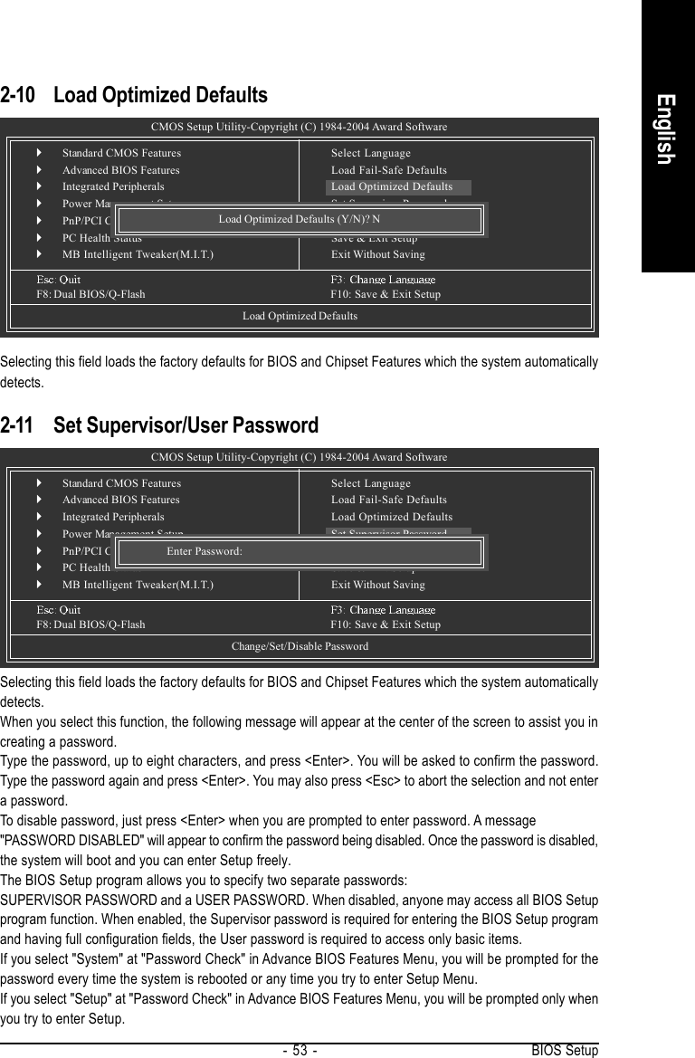
![GA-8AENXP-DW Motherboard - 52 -English2-9 Load Fail-Safe DefaultsFail-Safe defaults contain the most appropriate values of the system parameters that allow minimum systemperformance.CMOS Setup Utility-Copyright (C) 1984-2004 Award Software`Standard CMOS Features`Advanced BIOS Features`Integrated Peripherals`Power Management Setup`PnP/PCI Configurations`PC Health Status`MB Intelligent Tweaker(M.I.T.)Esc: QuitF8: Dual BIOS/Q-Flash F10: Save & Exit SetupLoad Fail-Safe DefaultsSelect LanguageLoad Fail-Safe DefaultsLoad Optimized DefaultsSet Supervisor PasswordSet User PasswordSave & Exit SetupExit Without SavingLoad Fail-Safe Defaults (Y/N)? N2-8 Select LanguageMulti-language supports 7 languages. There are English, French, German, Spanish, Traditional Chinese,Simplified Chinese, and Japanese.CMOS Setup Utility-Copyright (C) 1984-2004 Award Software`Standard CMOS Features`Advanced BIOS Features`Integrated Peripherals`Power Management Setup`PnP/PCI Configurations`PC Health Status`MB Intelligent Tweaker(M.I.T.)F8: Dual BIOS/Q-Flash F10: Save & Exit SetupSelect LanguageLoad Fail-Safe DefaultsLoad Optimized DefaultsSet Supervisor PasswordSet User PasswordSave & Exit SetupExit Without SavingSelect LanguageEnglish.........................[]Francais.......................[ ]Deutsch.......................[ ]Espanol........................[ ].....................[ ].....................[ ].........................[ ]KL: Move ENTER: AcceptESC: AbortCPU Voltage ControlSupports adjustable CPU Vcore from 0.8375V to 1.6000V. (Default value: Normal)Normal CPU VcoreDisplay your CPU Vcore voltage.](https://usermanual.wiki/GIGA-BYTE-TECHNOLOGY/GA-8AENXP-DW.Users-Manual-Part-2/User-Guide-517657-Page-22.png)

![Appendix- 69 -English3. Press Y button on your keyboard after you are sure to update BIOS. Then it will begin to update BIOS. The progress of updating BIOS will be displayed.Dual BIOS UtilityBoot From...................................... Main BiosMain ROM Type/Size...................... SST 49LF004A 512KBackup ROM Type/Size.................. SST 49LF004A 512KWide Range Protection DisableBoot From Main BiosAuto Recovery EnableHalt On Error Disable Copy Main ROM Data to BackupLoad Default SettingsSave Settings to CMOSQ-Flash UtilityLoad Main BIOS from FloppyLoad Backup BIOS from FloppySave Main BIOS to FloppySave Backup BIOS to FloppyEnter : Run KL:Move ESC:Reset F10:Power Off!! Copy BIOS completed - Pass !!Please press any key to continuePlease do not take out the floppy disk when it begins flashing BIOS.4. Press any keys to return to the Q-Flash menu when the BIOS updating procedure is completed.You can repeat Step 1 to4 to flash the backupBIOS, too.Dual BIOS UtilityBoot From...................................... Main BiosMain ROM Type/Size...................... SST 49LF004A 512KBackup ROM Type/Size.................. SST 49LF004A 512KWide Range Protection DisableBoot From Main BiosAuto Recovery EnableHalt On Error Disable Copy Main ROM Data to BackupLoad Default SettingsSave Settings to CMOSQ-Flash UtilityLoad Main BIOS from FloppyLoad Backup BIOS from FloppySave Main BIOS to FloppySave Backup BIOS to FloppyEnter : Run KL:Move ESC:Reset F10:Power OffAre you sure to RESET ?[Enter] to continure or [Esc] to abort...5. Press Esc and then Y button to exit the Q-Flash utility. The computer will restart automatically afteryou exit Q-Flash.After system reboots, you may find the BIOS version on your boot screen becomes the one you flashed.Intel i875P AGPset BIOS for 8KNXP Ultra FbaCheck System Health OK , VCore = 1.5250Main Processor : Intel Pentium(R) 4 1.6GHz (133x12)<CPUID : 0F27 Patch ID : 0027>Memory Testing : 131072K OKMemory Frequency 266 MHz in Single ChannelPrimary Master : FUJITSU MPE3170AT ED-03-08Primary Slave : NoneSecondary Master : CREATIVEDVD-RM DVD1242E BC101Secondary Slave : NonePress DEL to enter SETUP / Dual BIOS / Q-Flash / F9 For Xpress Recovery09/23/2003-i875P-6A79BG03C-00Award Modular BIOS v6.00PG, An Energy Star AllyCopyright (C) 1984-2003, Award Software, Inc.The BIOS filebecomes Fba afterupdating.](https://usermanual.wiki/GIGA-BYTE-TECHNOLOGY/GA-8AENXP-DW.Users-Manual-Part-2/User-Guide-517657-Page-39.png)
![GA-8AENXP-DW Motherboard - 72 -English3. Press Y button on your keyboard after you are sure to update BIOS.Then it will begin to update BIOS. The progress of updating BIOS will be shown at the same time.Q-Flash Utility V1.30 Flash Type/Size.................................SST 49LF003A 256KKeep DMI Data EnableUpdate BIOS from FloppySave BIOS to FloppyEnter : Run KL:Move ESC:Reset F10:Power OffUpdating BIOS Now>>>>>>>>>>>>>>>>>>>.........................Don't Turn Off Power or Reset SystemDo not trun off power orreset your systemat this stage!!4. Press any keys to return to the Q-Flash menu when the BIOS updating procedure is completed.Q-Flash Utility V1.30 Flash Type/Size.................................SST 49LF003A 256KKeep DMI Data EnableUpdate BIOS from FloppySave BIOS to FloppyEnter : Run KL:Move ESC:Reset F10:Power Off!! Copy BIOS completed - Pass !!Please press any key to continue5. Press Esc and then Y button to exit the Q-Flash utility. The computer will restart automatically afteryou exit Q-Flash.Q-Flash Utility V1.30 Flash Type/Size.................................SST 49LF003A 256KKeep DMI Data EnableUpdate BIOS from FloppySave BIOS to FloppyEnter : Run KL:Move ESC:Reset F10:Power OffAre you sure to RESET ?[Enter] to continure or [Esc] to abort...After system reboots, you may find the BIOS version on your boot screen becomes the one you flashed.Intel 845GE AGPSet BIOS for 8GE800 F4Check System Health OKMain Processor : Intel Pentium(R) 4 1.7GHz (100x17.0)<CPUID : 0F0A Patch ID : 0009>Memory Testing : 122880K OK + 8192K Shared MemoryPrimary Master : FUJITSU MPE3170AT ED-03-08Primary Slave : NoneSecondary Master : CREATIVEDVD-RM DVD1242E BC101Secondary Slave : NonePress DEL to enter SETUP / Q-Flash03/18/2003-I845GE-6A69YG01C-00Award Modular BIOS v6.00PG, An Energy Star AllyCopyright (C) 1984-2003, Award Software, Inc.The BIOS filebecomes F4 afterupdating6. Press Del to enter BIOS menu after system reboots and "Load BIOS Fail-Safe Defaults". See howto Load BIOS Fail-Safe Defaults, please kindly refer to Step 6 to 7 in Part One.Congratulation!! You have updated BIOS successfully!!](https://usermanual.wiki/GIGA-BYTE-TECHNOLOGY/GA-8AENXP-DW.Users-Manual-Part-2/User-Guide-517657-Page-42.png)
![GA-8AENXP-DW Motherboard - 76 -EnglishPlease follow the steps below to construct a complete RAID array:1) Have ready your hard drives for RAID construction.Note: To achieve best performance, it is recommended that the hard drives used are of similar makeand storage capacity.2) Please attach the hard drive connectors to their appropriate location on the motherboard ie. IDE, SCSI,or SATA.3) Enter the motherboard BIOS and locate RAID setup (Please refer to the section on Integrated Peripherals).4) Enter RAID setup in the BIOS and select the RAID type (For instance, enter Ctrl + I to select Intel RAID;Ctrl + S to select Silicon Image).5) Complete driver installation.6) Complete RAID utility installation.More information on steps 4 and 5 is provided. (For more detailed setup information, please visit "Support\Motherboard\ Technology Guide section" on our website at http:\\www.gigabyte.com.tw to read or downloadthe information you need.) Sections below introduce the steps to configure Intel and Promise RAID BIOS.A. Configuring the Intel RAID BIOSThe Intel RAID BIOS setup lets you choose the RAID array type and which hard drives you want to make partof the array.Entering the RAID BIOS Setup1. After rebooting your computer, wait until you see the RAID software prompting you to press Ctrl + I. TheRAID prompt appears as part of the system POST and boot process prior to loading the OS. You have a fewseconds to press Ctrl + I before the window disappears.Press Ctrl + I. The Intel RAID Utility - Create RAID Volume window appears (as Figure below).Intel(R) Application Accelerator RAID Option ROM v4.0.6180Copyright(C) 2003-04 Intel Corporation. All Rights Reversed.RAID Volumes :None Defined.Physical Disks :Port Driver Model Serial # Size Type/Status(Vol ID)0 ST3120026AS 3JT354CP 111.7GB Non-RAID Disk1 ST3120026AS 3JT329JX 111.7GB Non-RAID DiskPress <CTRL - I> to enter Configuration UtilityIntel(R) Application Accelerator RAID Option ROM v4.0.6180Copyright(C) 2003-04 Intel Corporation. All Rights Reversed.[ MAIN MENU ]1. Create RAID Volume 2. Delete RAID Volume 3. Reset Disks to Non-RAID 4. Exit[ DISK/VOLUME INFORMATION ]RAID Volumes :None Defined.Physical Disks :Port Driver Model Serial # Size Type/Status(Vol ID)0 ST3120026AS 3JT354CP 111.7GB Non-RAID Disk1 ST3120026AS 3JT329JX 111.7GB Non-RAID Disk[KL]-Select [ESC]-Exit [ENTER]-Select Menu](https://usermanual.wiki/GIGA-BYTE-TECHNOLOGY/GA-8AENXP-DW.Users-Manual-Part-2/User-Guide-517657-Page-46.png)
![Appendix- 77 -EnglishCreate RAID VolumePress Enter under Create RAID Volume to set up RAID.Intel(R) Application Accelerator RAID Option ROM v4.0.6180Copyright(C) 2003-04 Intel Corporation. All Rights Reversed.[ CREATE VOLUME MENU ][ HELP ]Enter a string between 1 and 16 characters in length that can be usedto uniquely identify the RAID volume. This name is case sensitive andcan not contain special characters.[KL]-Change [TAB]-Next [ESC]-Previous Menu [ENTER]-SelectName : RAID_Volume0RAID Level : RAID0(Stripe)Disks : Select DisksStrip Size : 128KBCapacity : 223.5 GBCreate VolumeAfter entering the Create Volume Menu, you can set disk name with 1~16 letters (letters cannot be specialcharacters) under Name item.After setting disk name, press Enter to select RAID Level.Intel(R) Application Accelerator RAID Option ROM v4.0.6180Copyright(C) 2003-04 Intel Corporation. All Rights Reversed.[ CREATE VOLUME MENU ][ HELP ]Choose the RAID level best suited to your usage model.RAID0(Stripe)- Creates a volume where equal portions of the volumeare spread across all the disks. This creates a volumewith higher performance by accessing all disks at once.RAID1(Stripe)- Creates a volume where a redundant copy of the data isstored on each disk. This creates a volume protectedfrom a single hard disk failure.[KL]-Change [TAB]-Next [ESC]-Previous Menu [ENTER]-SelectName : RAID_Volume0RAID Level : RAID0(Stripe)Disks : Select DisksStrip Size : 128KBCapacity : 223.5 GBCreate VolumeThere are two RAID levels: RAID0(Stripe) and RAID1(Mirror). After selecting the RAID level, press Enter toselect Strip Size.](https://usermanual.wiki/GIGA-BYTE-TECHNOLOGY/GA-8AENXP-DW.Users-Manual-Part-2/User-Guide-517657-Page-47.png)
![GA-8AENXP-DW Motherboard - 78 -EnglishThe KB is a unit of Strip Size. You can set disk block size with this item.The disk block size can be set from 4KB to 128KB. After you set disk block size, press Enter to set diskCapacity.Intel(R) Application Accelerator RAID Option ROM v4.0.6180Copyright(C) 2003-04 Intel Corporation. All Rights Reversed.[ CREATE VOLUME MENU ][ HELP ]Choose the RAID level best suited to your usage model.The following are typical values:16KB - Best for sequential transfers64KB - Good general purpose strip size128KB - Best performance for most desktops and workstations[KL]-Change [TAB]-Next [ESC]-Previous Menu [ENTER]-SelectName : RAID_Volume0RAID Level : RAID0(Stripe)Disks : Select DisksStrip Size : 128KBCapacity : 223.5 GBCreate VolumeIntel(R) Application Accelerator RAID Option ROM v4.0.6180Copyright(C) 2003-04 Intel Corporation. All Rights Reversed.[ CREATE VOLUME MENU ][ HELP ]Enter the volume capacity. The default value indicates themaximum volume capacity using the selected disks. If lessthan the maximum capacity is chosen, creation of a secondvolume is needed to utilize the remaining space.[KL]-Change [TAB]-Next [ESC]-Previous Menu [ENTER]-SelectName : RAID_Volume0RAID Level : RAID0(Stripe)Disks : Select DisksStrip Size : 128KBCapacity : 223.5 GBCreate VolumePress Enter to enter Create Volume after setting disk capacity.](https://usermanual.wiki/GIGA-BYTE-TECHNOLOGY/GA-8AENXP-DW.Users-Manual-Part-2/User-Guide-517657-Page-48.png)
![Appendix- 79 -EnglishPress Enter under the Create Volume item.Intel(R) Application Accelerator RAID Option ROM v4.0.6180Copyright(C) 2003-04 Intel Corporation. All Rights Reversed.[ CREATE VOLUME MENU ][ HELP ]Press "ENTER" to Create the specified volume[KL]-Change [TAB]-Next [ESC]-Previous Menu [ENTER]-SelectName : RAID_Volume0RAID Level : RAID0(Stripe)Disks : Select DisksStrip Size : 128KBCapacity : 223.5 GBCreate VolumeAn alert bar will be displayed warning you that all data on selected disks will be lost. Please press Y tocomplete the set-up of RAID.Intel(R) Application Accelerator RAID Option ROM v4.0.6180Copyright(C) 2003-04 Intel Corporation. All Rights Reversed.[ CREATE VOLUME MENU ][ HELP ]Press "ENTER" to Create the specified volume[KL]-Change [TAB]-Next [ESC]-Previous Menu [ENTER]-SelectName : RAID_Volume0RAID Level : RAID0(Stripe)Disks : Select DisksStrip Size : 128KBCapacity : 223.5 GBCreate VolumeWARNING : ALL DATA ON SELECTED DISKS WILL BE LOST.Are you sure you want to creat this volume? (Y/N) :](https://usermanual.wiki/GIGA-BYTE-TECHNOLOGY/GA-8AENXP-DW.Users-Manual-Part-2/User-Guide-517657-Page-49.png)
![GA-8AENXP-DW Motherboard - 80 -EnglishAfter the completion, you will see the detailed information about the RAID, such as RAID level, disk blocksize, disk name and disk capacity, etc.Intel(R) Application Accelerator RAID Option ROM v4.0.6180Copyright(C) 2003-04 Intel Corporation. All Rights Reversed.[ MAIN MENU ]1. Create RAID Volume 2. Delete RAID Volume 3. Reset Disks to Non-RAID 4. Exit[ DISK/VOLUME INFORMATION ]RAID Volumes :ID Name Level Strip Size Status Bootable0 RAID_Volume0 RAID(Stripe) 128KB 223.5GB Normal YesPhysical Disks :Port Driver Model Serial # Size Type/Status(Vol ID)0 ST3120026AS 3JT354CP 111.7GB Member Disk(0)1 ST3120026AS 3JT329JX 111.7GB Member Disk(0)[KL]-Select [ESC]-Exit [ENTER]-Select MenuDelete RAID VolumeIf you want to delete a RAID volume, please select the Delete RAID Volume option. Press Enter key andfollow the instructions on the screen.Intel(R) Application Accelerator RAID Option ROM v4.0.6180Copyright(C) 2003-04 Intel Corporation. All Rights Reversed.[ MAIN MENU ]1. Create RAID Volume2. Delete RAID Volume 3. Reset Disks to Non-RAID 4. Exit[ DISK/VOLUME INFORMATION ]RAID Volumes :ID Name Level Strip Size Status Bootable0 RAID_Volume0 RAID(Stripe) 128KB 223.5GB Normal YesPhysical Disks :Port Driver Model Serial # Size Type/Status(Vol ID)0 ST3120026AS 3JT354CP 111.7GB Member Disk(0)1 ST3120026AS 3JT329JX 111.7GB Member Disk(0)[KL]-Select [ESC]-Exit [ENTER]-Select Menu](https://usermanual.wiki/GIGA-BYTE-TECHNOLOGY/GA-8AENXP-DW.Users-Manual-Part-2/User-Guide-517657-Page-50.png)
![Appendix- 81 -EnglishB. Configuring the Promise PDC20779 RAID BIOSThe Promise PDC20779 RAID BIOS setup lets you choose the RAID array type and which hard drivesyou want to make part of the array.Entering the RAID BIOS Setup1. After rebooting your computer, wait until you see the RAID software prompting you to press Ctrl + F.The RAID prompt appears as part of the system POST and boot process prior to loading the OS. Youhave a few seconds to press Ctrl + F before the window disappears.Press <Ctrl> + <F>. The Promise RAID Utility window appears (as Figure below).FastTrak 779 (tm) BIOS Version 2.00.0.24Copyright (c) 2003 Promise Technology, Inc.Updated in 2004No Array is defined..............................Press <Ctrl-F> to enter FastBuild (tm) Utility orPress [ESC] to continue bootingFastBuild (tm) 2.03 (c) 2003-2005 Promise Technology, Inc.Auto Setup..................................................[ 1 ]View/Change Drives Assignments............[ 2 ]Define Array.............................................[ 3 ]Delete Array............................................. [ 4 ]Rebuild Array............................................[ 5 ][ Main Menu] ][ Keys Available]Press 1..5 to Select Options [ESC] ExitMain MenuThis is the first option screen when you enter the FastBuild Setup.To create a new array automatically, press <1>. Promise recommends this option for most users.To manually create an array, press <3> to enter the Define Array window. If you wish to specify blocksize, you must create the array manually.To view the disk drivers assigned to arrays, press <2> to enter the View Drive Assignments window.To delete an array, press <4> to enter the Delete Array window.To recover from an error in a mirrored (RAID 1) disk array, press <5> to enter the Rebuild Array window.](https://usermanual.wiki/GIGA-BYTE-TECHNOLOGY/GA-8AENXP-DW.Users-Manual-Part-2/User-Guide-517657-Page-51.png)
![GA-8AENXP-DW Motherboard - 82 -EnglishCreate Arrays AutomaticallyTo create a new array automatically, press 1 to enter the Auto Setup window. The Auto Setup selectionfrom the Main Menu can intuitively help create your disk array. It will assign all available drivesappropriate for the disk array you are creating.FastBuild (tm) 2.03 (c) 2003-2005 Promise Technology, Inc.Mode.......................................................................... StripeSpare Drive................................................................ 0Drives Used in Array................................................ 2Array Disk Capacity (size in MB)............................. 240068[ Auto Setup Options Menu] ]Optimize Array for: Performance[ Array Setup Configuration] ][ Keys Available][I, , Space] Change Option [ESC] Exit [CTRL-Y] SaveUnder the Optimized Array for setting, use the LEFT ARROW <I> or SPACEBAR key to selectPerformance (RAID 0) or Security (RAID 1). Press CTRL and Y to save the configuration.Performance: Under the Performance setting (RAID 0), FastTrak assigns two drives to a single Stripedarray. If you want a one-drive array or you want to specify block size, please go to the Define Arraywindows.Security: Under the Security setting (RAID 1), FastTrak assigns two drives to a single Mirrored array.](https://usermanual.wiki/GIGA-BYTE-TECHNOLOGY/GA-8AENXP-DW.Users-Manual-Part-2/User-Guide-517657-Page-52.png)
![Appendix- 83 -EnglishCreate Arrays ManuallyTo create a new array manually, press 3 to enter the Define Array window. The Define Array selectionfrom the Main Menu allows users to begin the process of manually defining the drive elements andRAID levels for one or multiple disk arrays attached to the Promise PDC20779 controller.Halt on ErrorWhen enabled, if the RAID controller detects an error, the boot process will stop when the FastTrakBIOS appears and wait for your input. At that point, you can press <Ctrl>+<F> to enter the FastBuildutility or press <ESC> to continue booting.When disabled, the FastTrak BIOS will appear and show the Critical array, but the computer willcontinue booting if you take no action.Use arrow keys [KL] to move to a logical disk set and press ENTER to enter the Define Array Menu.RAID Mode: Use Space key to change your selection between Stripe (RAID 0) or Mirror (RAID 1)FastBuild (tm) 2.03 (c) 2003-2005 Promise Technology, Inc.[ Define Array Menu][ Drives Assignments] ][ Keys Available] ]Logical Disk No RAID Mode Total Drv StatusLogical Disk 1 Stripe 0 FunctionalStripe Block: 64KB Gigabyte Rounding: OFF[K] Up [L] Down [ESC] Exit [Space] Change Option [Ctrl-Y] SaveChannel:ID Drive Model Capacity (MB) Assignment1:SATA ST3120026AS 120034 N2:SATA ST3120026AS 120034 NFastBuild (tm) 2.03 (c) 2003-2005 Promise Technology, Inc.[ Define Array Menu] ]Halt On Error: Disabled[ Keys Available] ][K] Up [L] Down [ESC] Exit [Enter] Select [Space] Change HOE OptionLogical Disk No RAID Mode Total Drv Capacity (MB) StatusLogical Disk1 ---- ---- ----- ----Logical Disk2 ---- ---- ----- ----Logical Disk3 ---- ---- ----- ----Logical Disk4 ---- ---- ----- ----](https://usermanual.wiki/GIGA-BYTE-TECHNOLOGY/GA-8AENXP-DW.Users-Manual-Part-2/User-Guide-517657-Page-53.png)
![GA-8AENXP-DW Motherboard - 84 -EnglishStripe Block: For striped (RAID 0) arrays, you can manually select the stripe block size. Press theSpace bar to scroll through choices from 32 to 128KB. The default is 64KB.Gigabyte Rounding: The Gigabyte Rounding feature is designed for Mirrored (RAID 1) arrays in whicha drive has failed and the user cannot replace the drive with the same capacity or larger.In the following procedure, we'll create RAID 0 as an example.1. Under the RAID Mode section, press the Spacebar to select Stripe.2. Set the Stripe Block size. 64K is the default.3. Under the Drive Assignments section, press the [KL] key to highlight a drive.4. Press the Spacebar to change the Assignment option to Y. This action adds the drive to the diskarray. Assign from one or two drives. If you assign only one drive, there will be no performancebenefit. The Total Drv section will show the number of disks assigned.5. Press <Ctrl>+<Y> keys to save the information. The window below will appear.6. Press <Y> to create and quick initialize the array or press <N> to create it only.7. Press <Esc> if you want to exit the RAID BIOS utility.Do you want to do quick initializeor create only? (Yes/No)Y-Create and Quick InitializeN-Create OnlyView Drive AssignmentsThe View Drive Assignments option in the Main Menu displays whether drives are assigned to a diskarray or are unassigned.Under the Assignment column, drives are labeled with their assigned disk array or shown as Spare ifunassigned.FastBuild (tm) 2.03 (c) 2003-2005 Promise Technology, Inc.[ View/Change Drives Assignments ]Mode (D=DMA, U=UDMA)[ Keys Available] ][K ,L,Space] Change Option [CTRL-Y] Save [ESC] ExitChannel:ID Drive Model Capacity (MB) Assignment Mode1:SATA ST3120026AS 120034 Logical Disk 1 U62:SATA ST3120026AS 120034 Logical Disk 1 U6](https://usermanual.wiki/GIGA-BYTE-TECHNOLOGY/GA-8AENXP-DW.Users-Manual-Part-2/User-Guide-517657-Page-54.png)
![Appendix- 85 -EnglishDelete an ArrayThe Delete Array menu option allows for deletion of disk array assignments.1. To delete an array, highlight the array you wish to delete and press the <Del> key.2. The View Array Definition Menu will appear (as shown below) showing which drives are assignedto this array. Press <Ctrl>+<Y> if you are sure to delete the array or other keys to abort.Deleting an existing disk array could result in loss of data. Record all arrayinformation including the array type, the disk members, and stripe block size incase you wish to undo a deletion.FastBuild (tm) 2.03 (c) 2003-2005 Promise Technology, Inc.[ Delete Array Menu] ][ Keys Available] ][K] Up [L] Down [ESC] Exit [Del] DeleteLogical Disk No RAID Mode Total Drv Capacity (MB) StatusLogical Disk1 Stripe 2 240068 FunctionalLogical Disk2 ---- ---- ----- ----Logical Disk3 ---- ---- ----- ----Logical Disk4 ---- ---- ----- ----FastBuild (tm) 2.03 (c) 2003-2005 Promise Technology, Inc.[ View Array Definition Menu][ Drives Assignments] ]Logical Disk No RAID Mode Total Drv Capacity (MB) StatusLogical Disk 1 Stripe 2 240068 FunctionalStripe Block: 64KB Gigabyte Rounding: OFFChannel:ID Drive Model Capacity (MB)1:SATA ST3120026AS 1200342:SATA ST3120026AS 120034Are you sure you want to delete this array?Press Ctrl-Y to Delete, or others to abort...3. Press <Y> to confirm yes to the following warning message and continue array deletion.4. At th next prompt, press <Ctrl>+<Y> to remove the boot sector or any keys to abort. When the arrayis deleted, the screen will return to Delete Array Menu. Press <Esc> if you want to exit the RAIDBIOS utility.Do you want to clear boot sector that willdelete any existing data on your hard disks?Y - Clear boot sector / N - Delete only](https://usermanual.wiki/GIGA-BYTE-TECHNOLOGY/GA-8AENXP-DW.Users-Manual-Part-2/User-Guide-517657-Page-55.png)