GIGA BYTE TECHNOLOGY GN-WI01GS Mini PCI Wireless Adapter User Manual GN WI01GS Manual
GIGA-BYTE TECHNOLOGY CO., LTD. Mini PCI Wireless Adapter GN WI01GS Manual
Contents
- 1. Users Manual 1
- 2. Users Manual 2
Users Manual 2
16
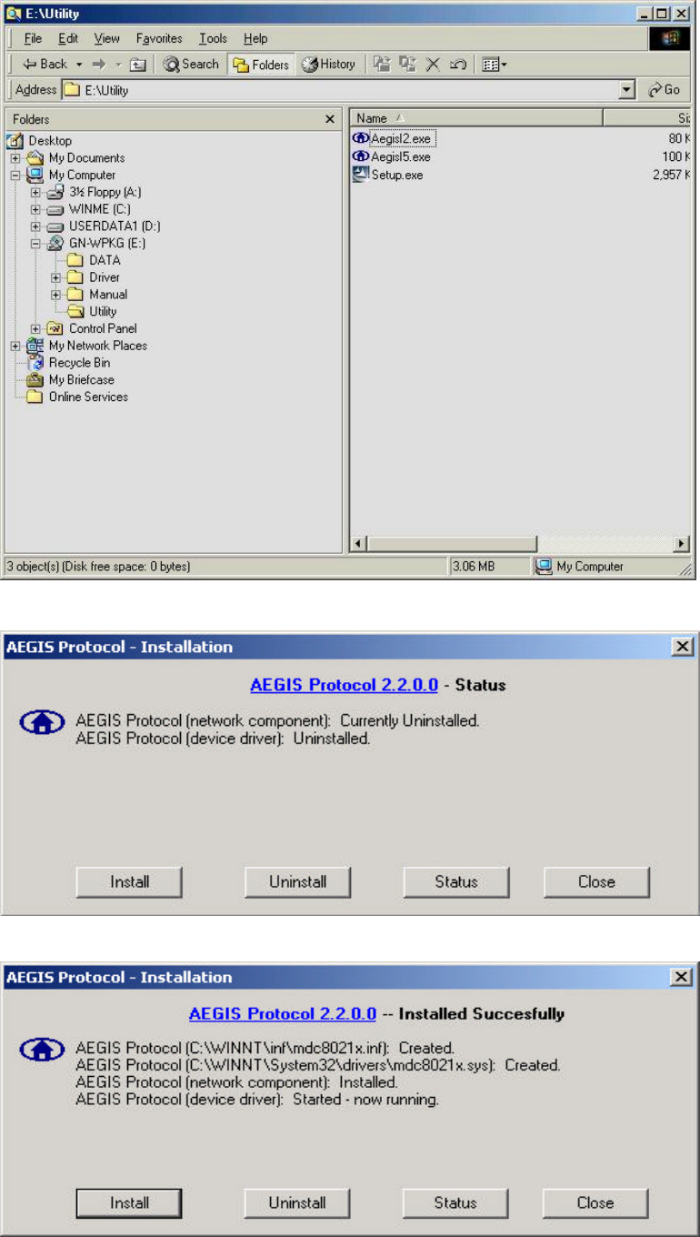
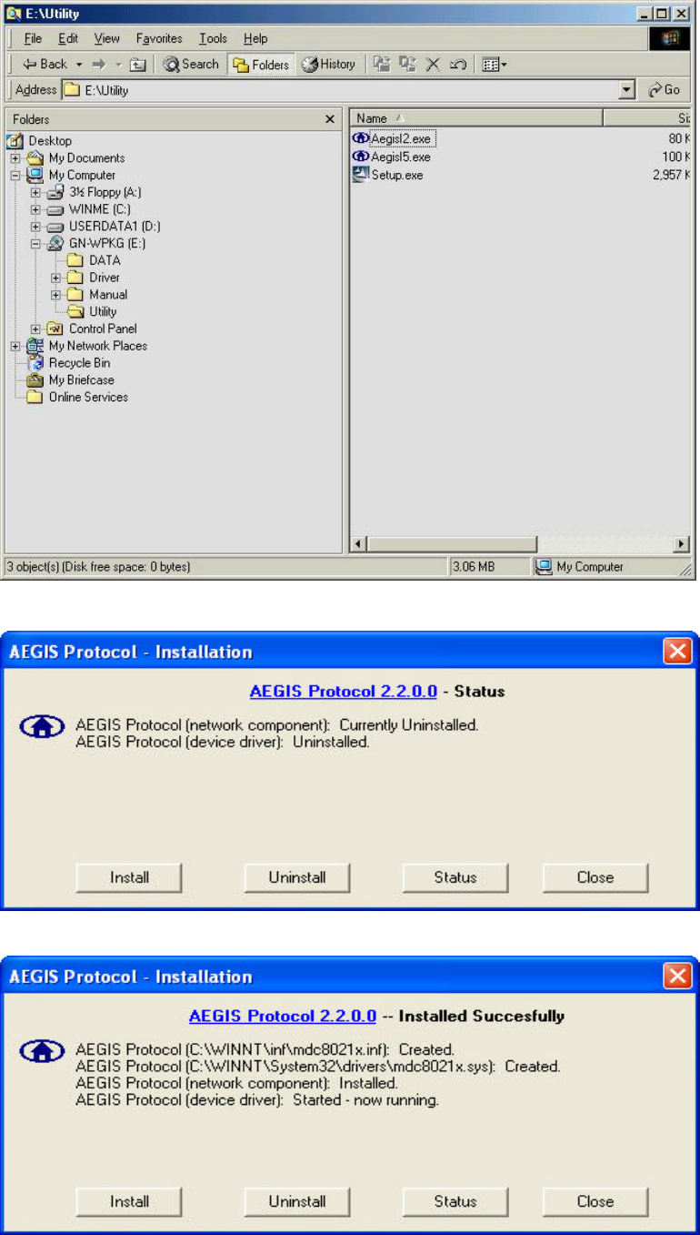
Step 10: Run “CD-ROM:\\Utility \AegisI2.exe” of the installation CD.
Step 11: Click “Install”.
Step 12: Click “Close”. Windows may reboot after the installation.
17
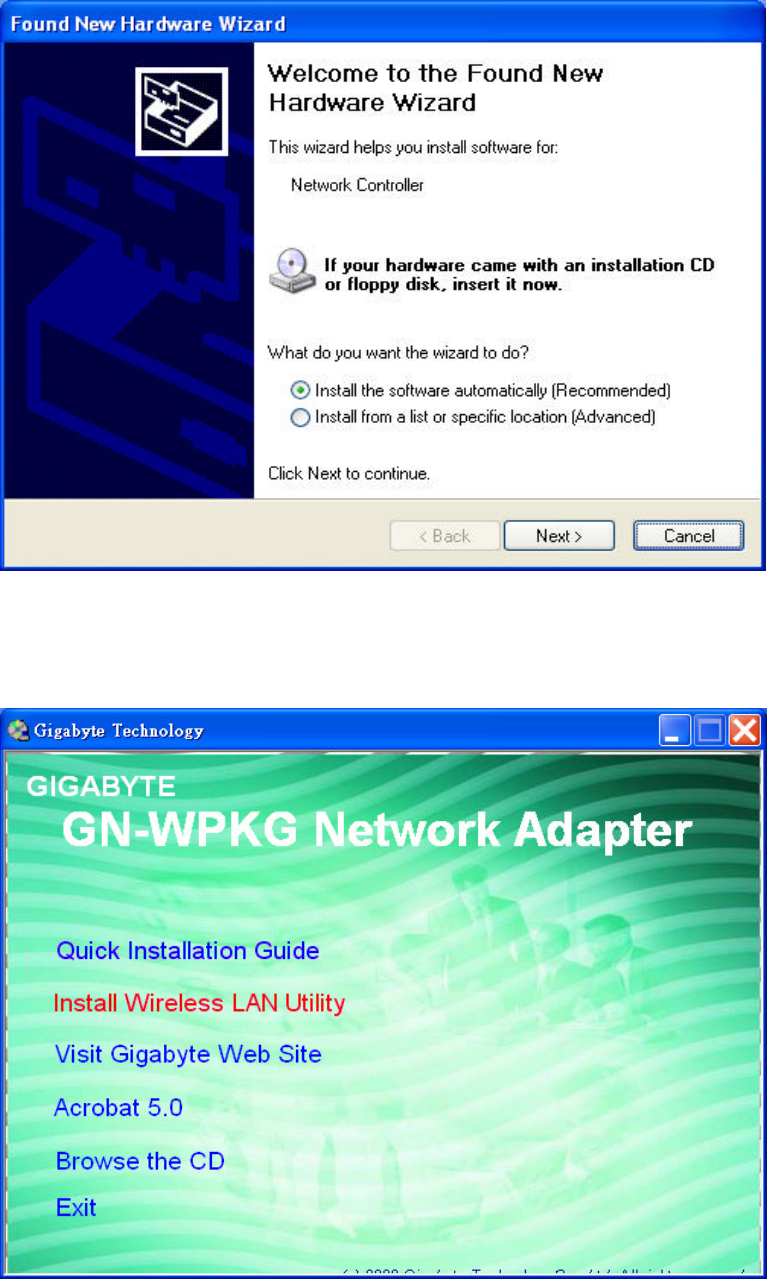
2-5. Installing The Driver & Utility (Win XP)
Step 1: Click “Cancel” for automatic installation.
Step 2: Insert the installation CD into the CD-ROM drive. The following window will pop
up.
Step 3: Click “Install Wireless LAN Utility”.
18
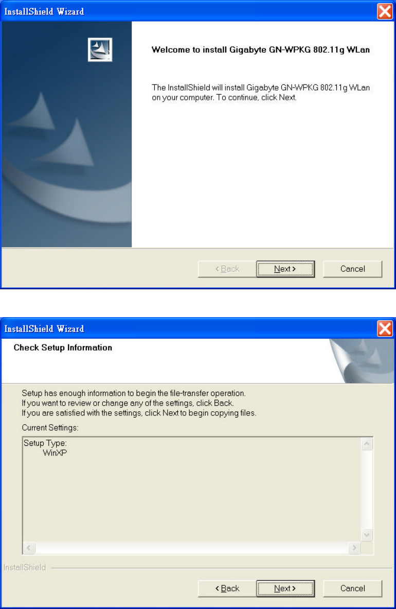
Step 4: Click “Next”.
Step 5: Click “Next”.
19
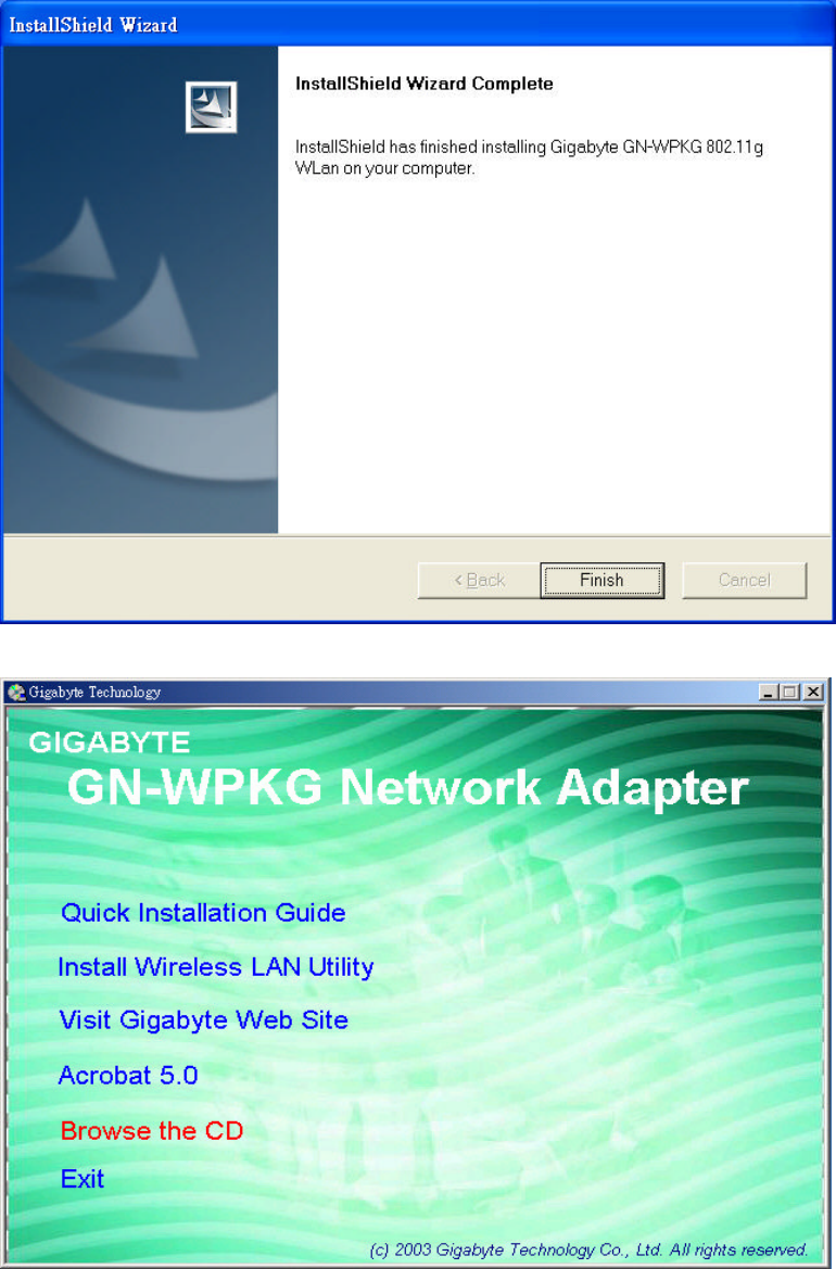
Step 6: Click “Finish”.
Step 7: To install 802.1X authentication function, click “Browse the CD”.
20
Step 8: Run “CD-ROM:\\Utility \AegisI5.exe” of the installation CD.
Step 9: Click “Install”.
Step 10: Click “Close”. Windows may reboot after the installation.
21
Chapter 3 Using the Utility
The Configuration & Monitor Utility is a powerful application that helps you to
configure the network card and monitor the statistics of the communication link. This
application permits the configuration for parameters while the card is operating. It also
offers more configuration options and supports Windows 98SE/Me/2000/XP. It appears as
an icon in the task bar at the bottom right corner of screen whenever the card is operating
(see Figure 3-1). The icon can tell you the received signal strength by four small lights.
You can open it by double-clicking on this icon.
Figure 3-1. The icon of the Configuration & Monitor Utility
You may double click this icon to open the utility or go to Windows Start menu, select
Programs, GIGA-BYTE 802.11 WLAN, GN-WI01GS and then GN-WI01GS Utility.
Note: You can use the utility to change configuration when the WLAN card is operating.
You have to use the network configuration tool provided by the operation system when the
WLAN card is not in use.
3-1.“Profile” Setting
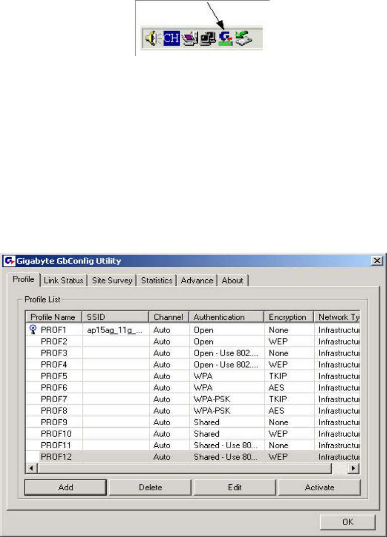
The “Profile” tab shows you the current association information about the profile. (see
Figure 3-2).
Figure 3-2. Current profile
22
Description of items in Figure 3-2 is as follows:
Profile Name: You can save various wireless settings for different environments.
: In use.
SSID: Displays the SSID of the WLAN card or Access Point.
Channel: Shows which channel is current in use.
Authentication: Authentication types currently in use include “OPEN”, “WPA”,
“WPA-PSK” and “Shared”.
Encryption: Four encryption types currently used in the profile include “None”, “WEP”,
“AES” and “TKIP”.
Network Type: Informs you if an Access Point (infrastructure) or other access points
(802.11 Ad Hoc) is connected. When it is 802.11 Ad Hoc, we can select a channel for all
members in 802.11 Ad Hoc.
ADD: Add profile (see Figure 3-3).
DELETE: Delete the selected profile.
EDIT: Edit the selected profile.
ACTIVATE: Activate the selected profile.
3-1-1. Configuration
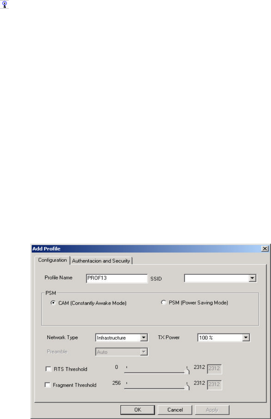
You can use ADD or EDIT button to set different configurations. (see Figure 3-3)
Figure 3-3. Configuration
23
Description of items in Figure 3-3 is as follows:
Profile Name: Users can save different profiles names for different configurations.
SSID: Select the AP detected by the system from the drop-down list or input a SSID.
Power Saving mode: Transceivers consume a lot of power in WLAN. Select “Power
Saving Mode” (PSM) to turn off transceivers when no data is transmitted or select CAM to
continuously turn on transceivers.
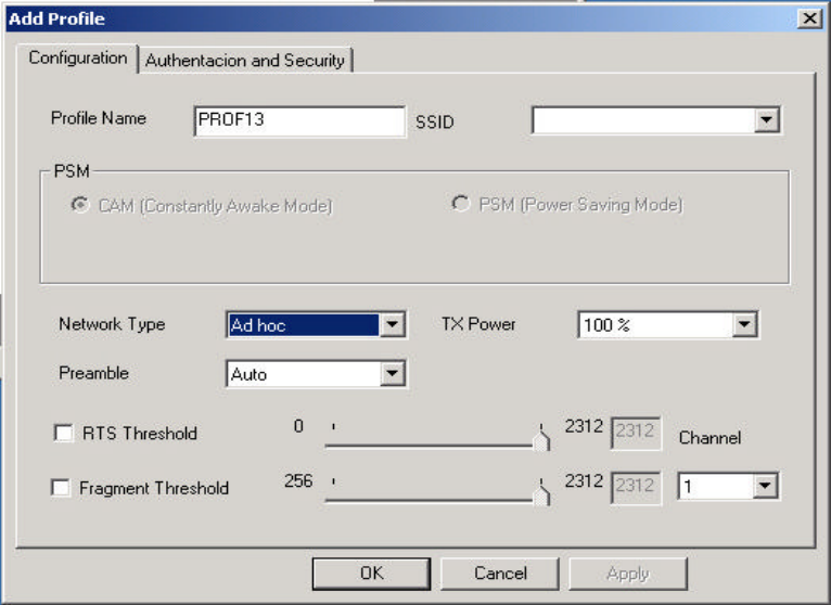
Network Type: “Infrastructure” and “802.11 Ad Hoc”. When the network type is
“Infrastructure”, PSM will function but not Preamble. On the contrary, when the network
type is “802.11 Ad Hoc”, Preamble will function but not PSM. Besides, Channel option will
appear (see Figure 3-4) and 802.1X Authentication will not function.
Figure 3-4
TX Power: Select percentage of transmitted power.
RTS Threshold: This is a mechanism implemented to prevent the “Hidden Node” problem,
“Hidden Note” is a situation in which two stations are within range of the same Access
Point, but are not within range of each other. Therefore, they are hidden nodes for each
other and can not detect each other. This mechanism is a way to prevent data collision
when WLAN equipments require transmission.
Fragment Threshold: Fragmentation mechanism is used for improving the efficiency
when high traffic flows along in the wireless network.
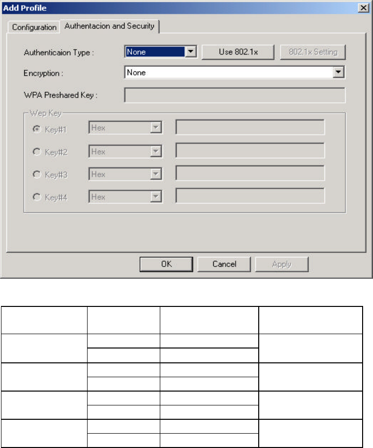
3-1-2. Authentication and Security:
If an authentication or security setting is configured in your Access Point or router, you
must enable this function to ensure successful connection. Use the following tab to
configure data security and ID authentication (see Figure 3-5). You may configure
different settings in the profile, including 802.11 Protocol Authentication and Security and
802.1X Protocol.
24
Figure 3-5. Authentication and Security
Table 3-1
Authentication
Security Secure Key
Setting Use 802.1X
None None None WEP Key Setting YES
None None Shared WEP Key YES
TKIP None WPA AES None YES
TKIP WPA-PSK Key WPA-PSK AES WPA-PSK Key NO
3-1-2-1. 802.11 Authentication and Security
Authentication: Before a station connects to a SSID, the authentication type used by the
SSID must be known. Authentication types include OPEN SYSTEM, WAP, WAP-PSK and
SHARED.
Security: To prevent unauthorized access to data transmitted on the network, WLAN card
provide a data encryption of high security. Another station have to use the same password
and encryption to connect with you. Different authentication types have different level of
security. Please refer to Table 3-1.
WEP encryption: Select one of the four keys as the default encrypted key.
Users have to set key the connected to AP access point. If WEP Key is set to be manually
connected to AP, no record will be kept. WEP Key can only be saved through the setting
of profile.
1. Select one Key #.
2. Select one data type (Hex or ASCII).
3. Enter password. Please enter 26 hexadecimal digits or 13 ASCII digits.
4. Click “OK to save the settings.
25
WPA-PSK encryption: Use WPA-PSK (Preshared Key) for WPA-PSK encryption (TKIP
and AES).
The system will read the Key with different types of encryption according to the length of
Preshared Key.
1. Enter Preshared Key. Please enter 64 hexadecimal digits or 8~63 ASCII digits.
2. Click “OK to save these settings.
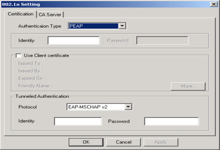
3-1-2-2. 802.1X Authentication
Click “Use 802.1X Authentication” and then “Enter 802.1X configuration”. When you
select this option, you may configure information about authentication, such as Tunnel
Protocol, ID and Password and Client Certificate or Certificate Chain. (see Figure 3-6 and
3-8)
Figure 3-6. 802.1X Authentication
Description of items in Figure 3-6 is as follows:
Authentication type: PEAP, TLS/Smart Card, TTLS, LEAP and MD5-Challenge.
Identity: Users’ accounts.
Password: Passwords for users’ accounts can be used when LEAP and MD5-Challenge
are selected as authentication types.
Use Client Certificate: This certificate is necessary for TLS and an option for PEPA and
TTLS. Check “Use Client Certificate” to confirm if the Client Certificate is correct in the
authentication process. Click “More” when selecting a Client Certificate (shown in Figure
3-7). Users can select one suitable certificate as Client Certificate.
Tunnel Authentication: PEPA and TTLS use two-step authentication method. The first
step is that Server sets up a Tunnel with its authentication. No option is need to be set for
Station with WLAN card. The second step is to confirm the validity of Station with assigned
26
authentication type in the Tunnel. Data needed for authentication includes Tunnel ID,
Tunnel Password, Client Certificate or Server Authentication.
Protocol: Use assigned authentication type in the safe tunnel.
Tunnel ID: Users’ accounts.
Password: Passwords for users’ accounts.
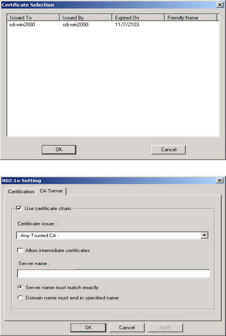
Figure 3-7. Client Certificate List
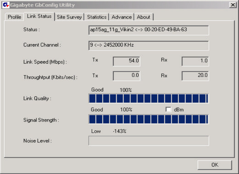
Figure 3-8. CA Server Setting
27
Description of items in Figure 3-8 is as follows:
CA Server is used when TLS, TTLS or PEAP is in use. The Client can verify if such server
is reliable and then transmit Client Certificate after the verification is confirmed. (if “Use
Client Certificate” is checked)
Verify CA server:
1. Confirm if the Server Certificate is issued by assigned certificate issuer. If “Allow
Intermediate Authentication” is checked, the server certificate can be issued by one
intermediate certificate issuer.
2. Check the server name of server certificate is the same as the name entered by the
user or belongs to the same domain.
Server Certificate: If “Server Certificate” is checked, it indicates that Client will confirm
whether CA server is reliable.
Certificate issuer: CA of a server certificate can be selected from certificate issuers on
the drop-down list.
Allow intermediate Certificates: When this option is checked, the certificate issuer can
be an issuer recognized by a specific certificate issuer. On the other hand, the server
certificate must be issued by a certificate issuer selected by the user.
Server name: This value can be a server name or the name of a domain where the server
is located.
Server name must match exactly: If this option is selected, the server name of server
certificate must be the same as “Server Name” or as the name of domain where the server
is located.
Domain name must end in specified name: If this option is selected, the certificate
issuer must be the domain or secondary domain entered in “Server Name”.
28
3-2.“Link Status” Setting
“Link Status” tab shows you the current association information about the card’s
connection with a wireless network. (see Figure 3-9)
Figure 3-9. Link Status
Description of items in Figure 3-9 is as follows:
Status: Shows current link status. “No Link” will appear on the screen when no connection
is available. Otherwise, SSID and BSSID of a link will appear.
Current Channel: The current channel number used by the WLAN card.
Link Speed: Transmission rate (transferring and receiving) at which data is transferred
between Stations with WLAN Card and AP. The speed will adjust according to different
modes (802.11b, 11g or mixed) or distance.
Throughput: displays the transmitting (Tx) and receiving (Rx) bytes per second.
Link Quality: Measures quality of the link according to the quality of received AP signal.
Signal Strength: Measures signal strength received by RF signal processor and displays
the signal strength in dBm.
Noise Level: Noise level during connection.
29
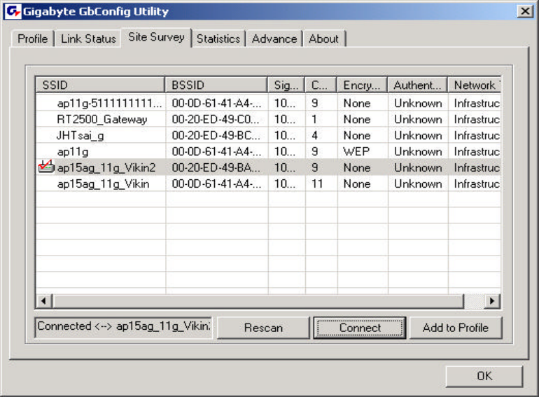
3-3.“Site Survey”
Setting “Site Survey” tab shows you the list of reachable access points and/or
peer-to-peer Stations. You can double click SSID that you want to connect or click
“Connect”. (see Figure 3-9)
Figure 3-10. Site Survey
Description of items in Figure 3-10 is as follows:
AP Account: Access Points’ accounts.
BSSID: Displays the MAC address of the Access Point or center station.
Signal Strength: Displays the strength of the signal from a station to the AP.
Channel: Displays the current channel number used by the Access Point.
Encryption: A security method used by the Access Point.
Authentication: The authentication type used by the Access Point.
Network Type: Informs you if an Access Point (infrastructure) or other stations (802.11 Ad
Hoc) is connected. When it is 802.11 Ad Hoc, we can select a channel for all members in
802.11 Ad Hoc.
RESCAN: Rescan the available network and then refresh the result.
Connect: Connects with a specific Access Point.
ADD PROFILE: Adds a specific Access Point into the profile.
30
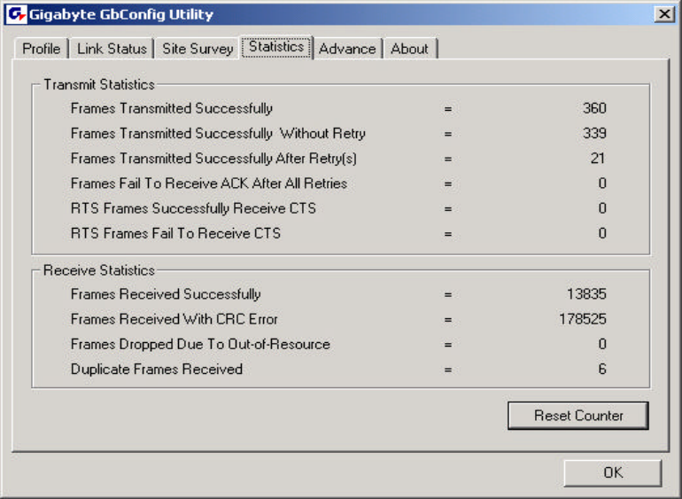
3-4.“Statistics” Setting
“Statistics” tab shows you the number of packets sent and received by the card (see
Figure 3-11)
Figure 3-11. Statistics
Description of items in Figure 3-11 is as follows:
Frames Transmitted Successfully: Number of frames transmitted successfully.
Frames Transmitted Successfully Without Retry: Number of frames transmitted
successfully, excluding packets transmitted successfully with more than one retry.
Frames Transmitted Successfully After Retry[s]: Number of frames transmitted
successfully with more than one retry.
Frames Fail To Receive ACK After All Retries: Number of frames failing to receive ACK
after many retries.
RTS Frames Successfully Receive CTS: Number of RTS frames successfully received
CTS (Clear To Send) from AP.
RTS Frames Fail To Receive CTS: Number of RTS frames fail to receive CTS from AP.
Frames Receive Successfully: Number of frames received successfully.
Frames Receive With CRC Error: Number of frames received with CRC Errors.
Frames Dropped Due TO Out-of-Resource: Number of frames dropped due to
out-of-resource.
Duplicate Frames Received: Number of duplicate frames received.
Reset Counter: Resets the counter to zero.
31
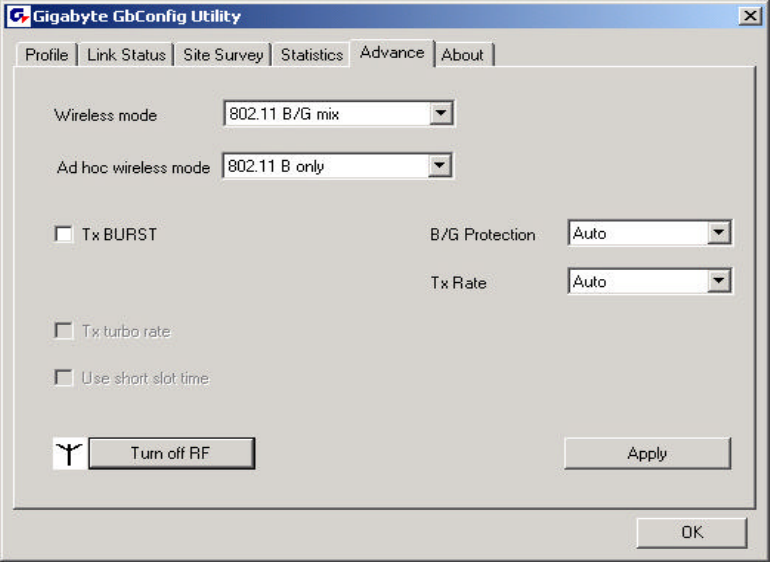
3-5.“Advance” Setting
“Advance” tab includes fields of various parameters to review or change drivers. Just
click “Apply” button to apply any parameter change to the driver in the tab. A reboot is not
needed for the WLAN card (see Figure 3-12)
Figure 3-12. Advance
Description of items in Figure 3-12 is as follows:
Wireless Mode: Sets infrastructure Protocols, including 802.11 B/G mix and 802.11 B
Only.
Ad Hoc Wireless Mode: Sets Ad Hoc Wireless Protocols, including 802.11 B/G mix,
802.11 B Only and 802.11 G Only.
TX Burst: The longest interval between frames is normally one DIFS while frames are
transmitted. When this setting is open, the longest interval between frames is one SIFS
that means the system is allowed to transmit higher capacity of data in one interval.
B/G Protection: 802.11b uses CCK modulation. 802.11g uses OFDM while CCK
modulation for 802.11b is compatible. To prevent data collision between two stations with
802.11b and 802.11g within range of the same Access Point, it is necessary to set 11B/G
Protection. This setting only functions when 802.11 B/G mix is selected as Wireless Mode.
Three setting are available: AUTO, EABLE and DISABLE.
This is a mechanism implemented to prevent the “Hidden Node” problem, “Hidden Note” is
a situation in which two stations are within range of the same Access Point, but are not
within range of each other. Therefore, they are hidden nodes for each other and can not
detect each other. This mechanism is a way to prevent data collision when WLAN
equipments require transmission.
TX Rate: This option adjusts settings of TX Rate according to the setting of “Infrastructure
Wireless Mode”.
Signal Control: To turn off transferring signals, click on “Turn Off RF” icon on the bottom
right corner of the screen. Click “Turn On RF” to transfer signal again.
TX Turbo rate and Use short slot time: currently does not support.
32
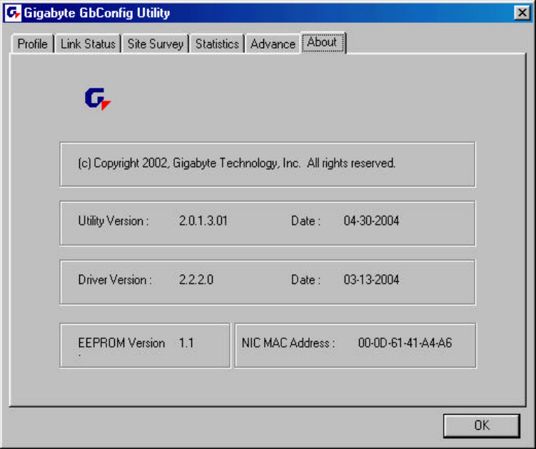
3-6.“About” Setting
“About” tab displays information about current drivers and physical MAC address (see
Figure 3-13).
Figure 3-13. About
33
Chapter 4 Troubleshooting
This troubleshooting guide provides answers to some common problems which you may
encounter while installing or using GIGABYTE WLAN card products. Contact the WLAN
Technical Support if you encounter problems not mentioned in this section.
u “802.1x”, “WPA” and “WPA-PSK” can not work
l Windows XP / 2000:
1. Run \Utility\AegisI5.exe. on the installation CD.
2. Click “Install”.
l Windows 98SE / ME:
1. Run \\Utility \AegisI2.exe on the installation CD.
2. Click “Install”.
u Cannot connect to an AP
l Make sure the SSID for the Wireless LAN Card is the same as the Access Point.
l Make sure the security settings are the same as that of Access Point. When WEP
or WPA encryption is enabled, check if the WEP or WPA keys for the WLAN and
AP are the same.
l Make sure if the MAC address of the WLAN card is added in the AP
Authorization Table.
u Can connect to an AP but cannot connect to the Internet
l Make sure the security settings are the same as that of Access Point. When WEP
or WPA encryption is enabled, check if the WEP or WPA keys for the WLAN and
AP are the same.
l Make sure the network configuration (IP address, subnet mask, gateway, and
DNS) of your computer are correct.
l Check the proxy server of the WEB browser is correctly set.
u Poor link quality and signal strength
l Keep the WLAN card away from microwave ovens and large metal objects to
avoid radio interference.
l Keep the distance between the WLAN card and the AP as close as possible.

34
Chapter 5 Specification
System
Host Interface MINI-PCI
Chipset Ralink MAC RT2561, Transceiver RT2527
Operating Voltages 3.3V+/-5%
Typical Power Transmitting: 370mA, Receiving: 220mA
RF – 802.11g (backward compatible to 802.11b)
Frequency Band 2412 ~ 2484 MHz (subject to local regulation)
Modulation Technology OFDM and DSSS
Modulation Techniques 64QAM, 16QAM, QPSK, BPSK, DBPSK, DQPSK, CCK
Data Rates 54, 48, 36, 24, 18, 12, 11, 9, 6, 5.5, 2, 1 Mbps, auto fallback
Output power Targeted at 17dBm @54Mbps, 19dBm @11Mbps
Receive Sensitivity Targeted at -71dBm @54Mbps; -84dBm@11Mbps
Antenna Connector Two RF connectors for support antenna diversity
Regulatory and Environmental Compliance
EMC certification FCC part 15 (USA)
Temperature Range Operating: 0 ~ 40 degree C, Storage: -20 ~ 65 degree C
Humidity 10% ~ 85% Non-condensing
Software
Driver Windows 98SE/Me/2000/XP
Security 64/128 bit WEP, WPA, WPA2, TKIP, 802.11i
Quality of Service (QoS) 802.11e, WMM
International Regulation 802.11d + h
Cisco Compliance CCX v1.0, v2.0, v3.0
Roaming Seamless roaming among 802.11b/g access points.
Management Utility Monitors the network situation.
Mechanical
Packaging Generic, Gigabyte, private labeling optional
Weight 12.0 ± 1.0g
Dimension 59.6mm*44.6mm*3.2mm ± 0.15mm
* Subject to change without notice.