GIGA BYTE TECHNOLOGY GN-WIAG02 IEEE 802.11b/g Wireless LAN Mini-PCI Card User Manual Anyplace Kiosk 4836 4838
GIGA-BYTE TECHNOLOGY CO., LTD. IEEE 802.11b/g Wireless LAN Mini-PCI Card Anyplace Kiosk 4836 4838
UserManual.wiki
>
GIGA BYTE TECHNOLOGY
>
GN-WIAG02 User Manual
>
manual
Contents
1.
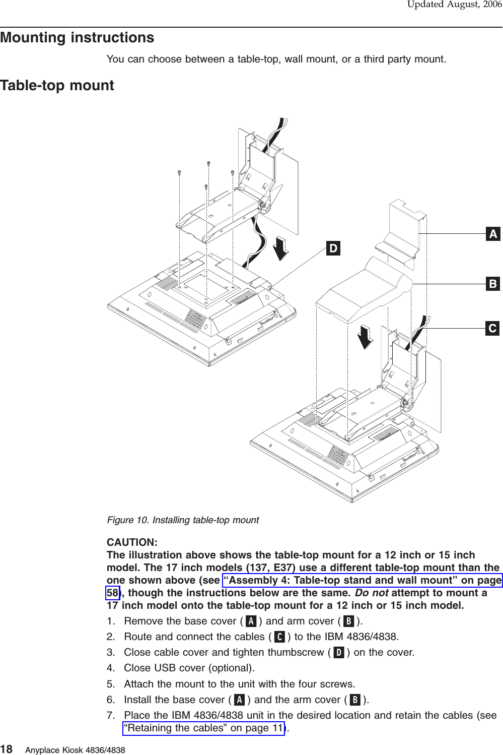
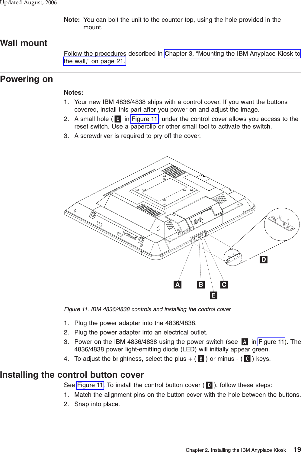
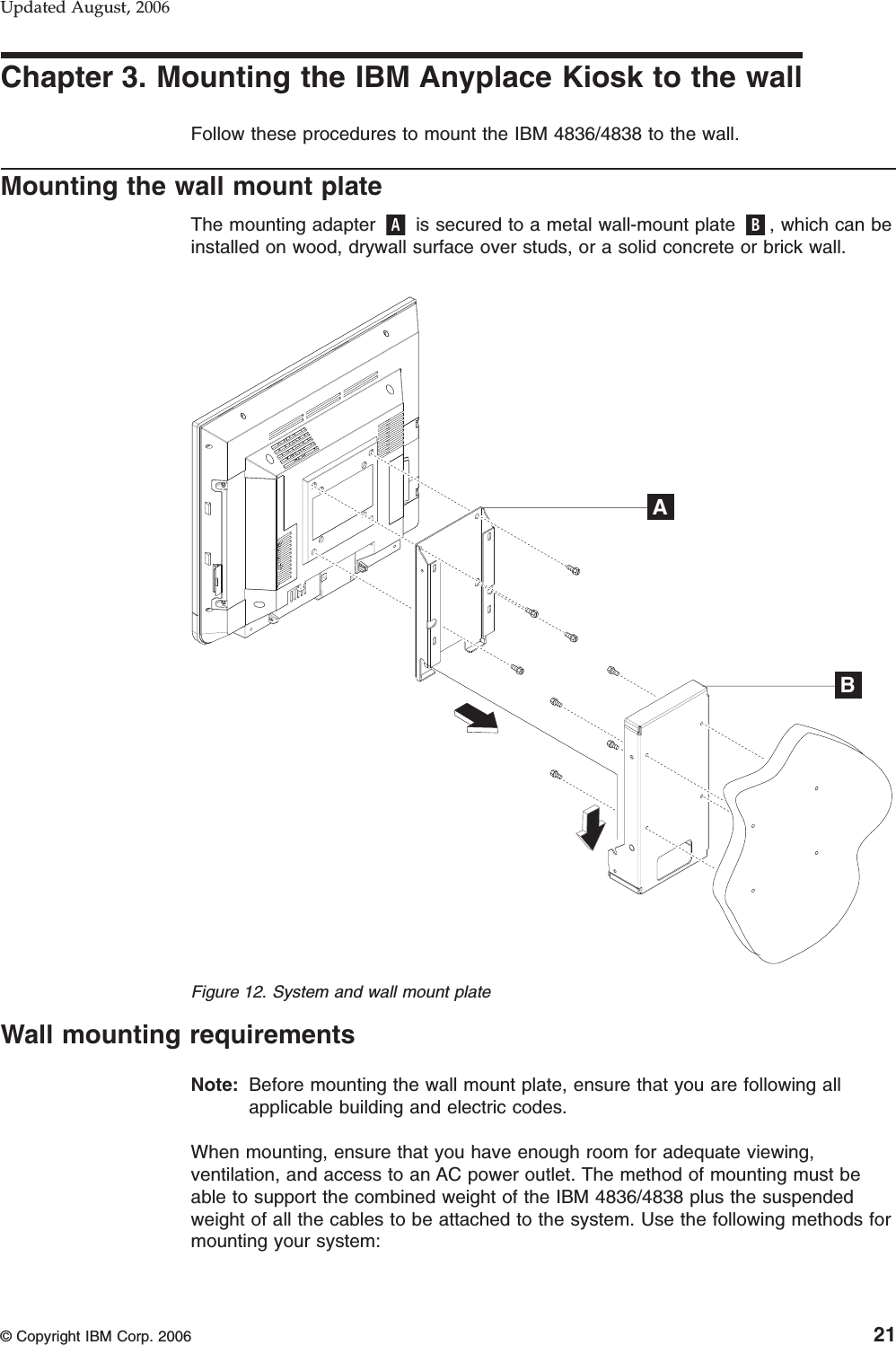
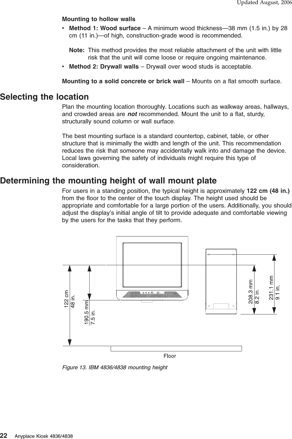
Users Manual
2.
manual
manual
Navigation menu
Upload a User Manual
Namespaces
Wiki Guide
HTML
PDF
Info
Views
User Manual
Discussion / Help
Navigation