GIGA BYTE TECHNOLOGY GN-WIAG02 IEEE 802.11b/g Wireless LAN Mini-PCI Card User Manual Anyplace Kiosk 4836 4838
GIGA-BYTE TECHNOLOGY CO., LTD. IEEE 802.11b/g Wireless LAN Mini-PCI Card Anyplace Kiosk 4836 4838
Contents
- 1. Users Manual
- 2. manual
manual
Anyplace Kiosk 4836/4838
Planning, Installation, and Service Guide
GA27-4347-01Updated August, 2006
Anyplace Kiosk 4836/4838
Planning, Installation, and Service Guide
GA27-4347-01Updated August, 2006

Note
Before using this information and the product it supports, be sure to read the general information in Appendix C, “Notices”
and the Appendix D, “Safety information.”
Second Edition (June 2006)
This edition applies to the IBM Anyplace Kiosk and to all subsequent releases and modifications until otherwise
indicated in new editions.
Current versions of Retail Store Solutions documentation are available on the IBM Retail Store Solutions Web site at:
http://www.ibm.com/solutions/retail/store/support/. Click Publications.
A form for reader’s comments is also provided at the back of this publication. If the form has been removed, address
your comments to:
IBM Corporation
Retail Store Solutions Information Development
Department ZBDA
PO Box 12195
Research Triangle Park, North Carolina 27709 USA
When you send information to IBM, you grant IBM a nonexclusive right to use or distribute whatever information you
supply in any way it believes appropriate without incurring any obligation to you.
© Copyright International Business Machines Corporation 2006. All rights reserved.
US Government Users Restricted Rights – Use, duplication or disclosure restricted by GSA ADP Schedule Contract
with IBM Corp.
Updated August, 2006

Contents
Figures . . . . . . . . . . . . . . . . . . . . . . . . . . . vii
Tables . . . . . . . . . . . . . . . . . . . . . . . . . . . .ix
About this guide . . . . . . . . . . . . . . . . . . . . . . . .xi
Who should read this guide . . . . . . . . . . . . . . . . . . . .xi
Related publications . . . . . . . . . . . . . . . . . . . . . . .xi
Accessibility . . . . . . . . . . . . . . . . . . . . . . . . . . xii
Tell us what you think . . . . . . . . . . . . . . . . . . . . . . xii
Summary of changes . . . . . . . . . . . . . . . . . . . . . . xiii
Update to GA27-4347-01 (January, 2007) . . . . . . . . . . . . . . . xiii
Update to GA27-4347-01 (August, 2006) . . . . . . . . . . . . . . . xiii
GA27-4347-01 (June, 2006) . . . . . . . . . . . . . . . . . . . . xiii
Update to GA27-4347-00 (June, 2005) . . . . . . . . . . . . . . . . xiii
Chapter 1. Introducing the IBM Anyplace Kiosk . . . . . . . . . . . .1
Architecture and attributes . . . . . . . . . . . . . . . . . . . . .2
Models and features . . . . . . . . . . . . . . . . . . . . . . .3
Optional features . . . . . . . . . . . . . . . . . . . . . . . .3
Configurations . . . . . . . . . . . . . . . . . . . . . . . . .4
Mounting options . . . . . . . . . . . . . . . . . . . . . . . .5
System software, touch drivers, and diagnostics . . . . . . . . . . . . .5
Supported operating systems . . . . . . . . . . . . . . . . . . . .5
Environmental requirements . . . . . . . . . . . . . . . . . . . .6
Power usage . . . . . . . . . . . . . . . . . . . . . . . . . .6
Calling for service . . . . . . . . . . . . . . . . . . . . . . . .6
Chapter 2. Installing the IBM Anyplace Kiosk . . . . . . . . . . . . .7
Rear view . . . . . . . . . . . . . . . . . . . . . . . . . . .8
Connectors . . . . . . . . . . . . . . . . . . . . . . . . . . .9
Installation steps . . . . . . . . . . . . . . . . . . . . . . . .10
Opening the cable covers . . . . . . . . . . . . . . . . . . . . .10
Retaining the cables . . . . . . . . . . . . . . . . . . . . . . .11
Installing the options . . . . . . . . . . . . . . . . . . . . . . .12
Installing the scanner . . . . . . . . . . . . . . . . . . . . .12
Installing the MSR (12 inch models) . . . . . . . . . . . . . . . .12
Installing the MSR (15 and 17 inch models) . . . . . . . . . . . . .14
Installing the upgrade options . . . . . . . . . . . . . . . . . . .16
Installing a hard drive . . . . . . . . . . . . . . . . . . . . .16
Installing additional memory . . . . . . . . . . . . . . . . . . .17
Mounting instructions . . . . . . . . . . . . . . . . . . . . . .18
Table-top mount . . . . . . . . . . . . . . . . . . . . . . .18
Wall mount . . . . . . . . . . . . . . . . . . . . . . . . .19
Powering on . . . . . . . . . . . . . . . . . . . . . . . . . .19
Installing the control button cover . . . . . . . . . . . . . . . . .19
Chapter 3. Mounting the IBM Anyplace Kiosk to the wall . . . . . . . .21
Mounting the wall mount plate . . . . . . . . . . . . . . . . . . .21
Wall mounting requirements . . . . . . . . . . . . . . . . . . .21
Selecting the location . . . . . . . . . . . . . . . . . . . . .22
Determining the mounting height of wall mount plate . . . . . . . . . .22
Wall mount plate mounting options . . . . . . . . . . . . . . . .23
Updated August, 2006
© Copyright IBM Corp. 2006 iii
||
!!
||
||
||
Attaching the wall mount plate . . . . . . . . . . . . . . . . . .23
Mounting to hollow walls . . . . . . . . . . . . . . . . . . . .24
Mounting to a concrete or brick wall . . . . . . . . . . . . . . . .26
Fastener types . . . . . . . . . . . . . . . . . . . . . . . .27
Chapter 4. Removing and replacing FRUs . . . . . . . . . . . . . .29
Reviewing the IBM 4836/4838 assembly . . . . . . . . . . . . . . .30
Before you begin . . . . . . . . . . . . . . . . . . . . . . .30
Removing the back cover . . . . . . . . . . . . . . . . . . . . .31
Removing the scanner and scanner window . . . . . . . . . . . . . .31
Removing the cable covers . . . . . . . . . . . . . . . . . . . .32
Removing the main shield . . . . . . . . . . . . . . . . . . . . .32
Removing the wireless card . . . . . . . . . . . . . . . . . . . .33
Locating and resetting the CMOS jumper . . . . . . . . . . . . . . .34
Removing the memory card . . . . . . . . . . . . . . . . . . . .34
Removing the hard drive fan . . . . . . . . . . . . . . . . . . . .35
Changing the battery . . . . . . . . . . . . . . . . . . . . . . .36
Removing the heat sink . . . . . . . . . . . . . . . . . . . . . .37
Removing the processor . . . . . . . . . . . . . . . . . . . . .38
Removing the hard disk drive and bracket . . . . . . . . . . . . . . .38
Removing the speakers . . . . . . . . . . . . . . . . . . . . . .39
Removing the system board . . . . . . . . . . . . . . . . . . . .40
Removing the control card . . . . . . . . . . . . . . . . . . . . .41
Removing the control buttons . . . . . . . . . . . . . . . . . .41
Removing the front panel card . . . . . . . . . . . . . . . . . . .42
Removing the backlight inverter card . . . . . . . . . . . . . . . . .43
Removing the LCD . . . . . . . . . . . . . . . . . . . . . . .44
Replacing the front bezel . . . . . . . . . . . . . . . . . . . . .46
Removing the mounting stand cover set . . . . . . . . . . . . . . .47
Removing the volume control card (Model 13V only) . . . . . . . . . . .48
Chapter 5. Troubleshooting problems . . . . . . . . . . . . . . .49
Appendix A. Field-replaceable units . . . . . . . . . . . . . . . .51
Assembly 1: 4836/4838 Models 132, E32, 13V, and W2D (12 inch) . . . . . .52
Assembly 2: 4836/4838 Models 135, E35, and W5D (15 inch) . . . . . . .54
Assembly 3: 4838 Models 137, E37, and W7D (17 inch) . . . . . . . . . .56
Assembly 4: Table-top stand and wall mount . . . . . . . . . . . . . .58
Power cords . . . . . . . . . . . . . . . . . . . . . . . . . .60
Appendix B. Product dimensions . . . . . . . . . . . . . . . . .61
12 inch models . . . . . . . . . . . . . . . . . . . . . . . . .61
15 inch models . . . . . . . . . . . . . . . . . . . . . . . . .62
17 inch models . . . . . . . . . . . . . . . . . . . . . . . . .63
Appendix C. Notices . . . . . . . . . . . . . . . . . . . . . .65
Anyplace Kiosk Class 2 laser notices . . . . . . . . . . . . . . . . .66
Class 2 laser notices . . . . . . . . . . . . . . . . . . . . . .66
Electronic emission notices . . . . . . . . . . . . . . . . . . . .68
Federal communications commission (FCC) statement . . . . . . . . .68
Industry Canada Class A emission compliance statement . . . . . . . .68
Avis de conformité aux normes d’Industrie Canada . . . . . . . . . .69
European Community (CE) mark of conformity statement . . . . . . . .69
Germany . . . . . . . . . . . . . . . . . . . . . . . . . .69
Australia / New Zealand . . . . . . . . . . . . . . . . . . . .70
Japanese power line harmonics compliance statement . . . . . . . . . .70
Updated August, 2006
iv Anyplace Kiosk 4836/4838
||
||
Japanese Voluntary Control Council for Interference (VCCI) statement . . . .70
Korean Communications Statement . . . . . . . . . . . . . . . . .70
Chinese Class A warning statement . . . . . . . . . . . . . . . . .71
Taiwanese Class A warning statement . . . . . . . . . . . . . . . .71
Taiwanese battery recycling statement . . . . . . . . . . . . . . . .71
Electrostatic discharge (ESD) . . . . . . . . . . . . . . . . . . .72
Regulatory notice for T60H786 or GN-WIAG02 IBM 802.11 b/g wireless LAN
mini PCI adapter . . . . . . . . . . . . . . . . . . . . . . .72
USA – Federal Communications Commission (FCC) . . . . . . . . . .72
Canada – Industry Canada (IC) Low Power License-Exempt Radio
Communication Devices (RSS-210) . . . . . . . . . . . . . . .73
Europe – EU declaration of conformity for IBM 11 b/g wireless LAN mini PCI
adapter . . . . . . . . . . . . . . . . . . . . . . . . . .74
Notice for users in Korea . . . . . . . . . . . . . . . . . . . .78
Notice for users in Singapore . . . . . . . . . . . . . . . . . .78
End of life disposal . . . . . . . . . . . . . . . . . . . . . .78
Mercury-added statement . . . . . . . . . . . . . . . . . . . .79
Macrovision copy protection technology . . . . . . . . . . . . . . . .79
Trademarks . . . . . . . . . . . . . . . . . . . . . . . . . .79
Appendix D. Safety information . . . . . . . . . . . . . . . . . .81
Glossary . . . . . . . . . . . . . . . . . . . . . . . . . . .87
Index . . . . . . . . . . . . . . . . . . . . . . . . . . . .95
Part number index . . . . . . . . . . . . . . . . . . . . . . .99
Updated August, 2006
Contents v
|
||
||
Updated August, 2006
vi Anyplace Kiosk 4836/4838

Figures
1. IBM Anyplace Kiosk Model 132 . . . . . . . . . . . . . . . . . . . . . . . . . .1
2. Rear view showing access doors, mounting holes, attachment holes . . . . . . . . . . . .8
3. IBM 4836/4838 connectors . . . . . . . . . . . . . . . . . . . . . . . . . . .9
4. Retaining the cables using cable ties . . . . . . . . . . . . . . . . . . . . . . .11
5. Installing the scanner . . . . . . . . . . . . . . . . . . . . . . . . . . . . .12
6. Installing the MSR (12 inch models) . . . . . . . . . . . . . . . . . . . . . . . .13
7. Installing the MSR (15 and 17 inch models) . . . . . . . . . . . . . . . . . . . . .15
8. Removing the hard drive cover . . . . . . . . . . . . . . . . . . . . . . . . . .16
9. Installing additional memory . . . . . . . . . . . . . . . . . . . . . . . . . . .17
10. Installing table-top mount . . . . . . . . . . . . . . . . . . . . . . . . . . . .18
11. IBM 4836/4838 controls and installing the control cover . . . . . . . . . . . . . . . .19
12. System and wall mount plate . . . . . . . . . . . . . . . . . . . . . . . . . .21
13. IBM 4836/4838 mounting height . . . . . . . . . . . . . . . . . . . . . . . . .22
14. Wall mount plate and wall cutout dimensions . . . . . . . . . . . . . . . . . . . .23
15. Exploded view of the IBM 4836/4838 assembly . . . . . . . . . . . . . . . . . . .30
16. Removing the back covers . . . . . . . . . . . . . . . . . . . . . . . . . . .31
17. Removing the main shield . . . . . . . . . . . . . . . . . . . . . . . . . . .32
18. Location of the CMOS jumper . . . . . . . . . . . . . . . . . . . . . . . . . .34
19. Removing the hard drive fan . . . . . . . . . . . . . . . . . . . . . . . . . .35
20. View of battery and heatsink . . . . . . . . . . . . . . . . . . . . . . . . . .36
21. Heat sink and processor . . . . . . . . . . . . . . . . . . . . . . . . . . . .37
22. Removing the hard disk drive and bracket . . . . . . . . . . . . . . . . . . . . .38
23. Removing the speakers . . . . . . . . . . . . . . . . . . . . . . . . . . . .39
24. Removing the system board . . . . . . . . . . . . . . . . . . . . . . . . . . .40
25. Removing the control card . . . . . . . . . . . . . . . . . . . . . . . . . . .41
26. Removing the front panel card . . . . . . . . . . . . . . . . . . . . . . . . . .42
27. Removing the backlight inverter card . . . . . . . . . . . . . . . . . . . . . . .43
28. Removing the LCD . . . . . . . . . . . . . . . . . . . . . . . . . . . . . .44
29. Replacing the LED assembly . . . . . . . . . . . . . . . . . . . . . . . . . .45
30. Replacing the front bezel . . . . . . . . . . . . . . . . . . . . . . . . . . . .46
31. Removing the stand cover set . . . . . . . . . . . . . . . . . . . . . . . . . .47
32. Removing the volume control card (Model 13V) . . . . . . . . . . . . . . . . . . .48
33. Dimensions for 12 inch models . . . . . . . . . . . . . . . . . . . . . . . . .61
34. Dimensions for 15 inch models . . . . . . . . . . . . . . . . . . . . . . . . .62
35. Dimensions for 17 inch models . . . . . . . . . . . . . . . . . . . . . . . . .63
36. Anyplace Kiosk Class 2 laser notices . . . . . . . . . . . . . . . . . . . . . . .66
37. Antenna operating range . . . . . . . . . . . . . . . . . . . . . . . . . . . .73
Updated August, 2006
© Copyright IBM Corp. 2006 vii
||
||
||
||
Updated August, 2006
viii Anyplace Kiosk 4836/4838

Tables
1. Summary of characteristics and weight by model . . . . . . . . . . . . . . . . . . .2
2. IBM Anyplace Kiosk models . . . . . . . . . . . . . . . . . . . . . . . . . . .3
3. IBM Anyplace Kiosk hardware options . . . . . . . . . . . . . . . . . . . . . . .3
4. Environmental requirements . . . . . . . . . . . . . . . . . . . . . . . . . . .6
5. Power usage . . . . . . . . . . . . . . . . . . . . . . . . . . . . . . . . .6
6. Connector location . . . . . . . . . . . . . . . . . . . . . . . . . . . . . . .9
7. Securing the wood support to the wood studs using lag screws . . . . . . . . . . . . . .25
8. Securing the wall mounting plate to a drywall surface . . . . . . . . . . . . . . . . .26
9. Fastener types . . . . . . . . . . . . . . . . . . . . . . . . . . . . . . .27
10. Power Cords . . . . . . . . . . . . . . . . . . . . . . . . . . . . . . . .60
Updated August, 2006
© Copyright IBM Corp. 2006 ix
Updated August, 2006
x Anyplace Kiosk 4836/4838

About this guide
This guide provides information on installing and servicing the IBM® Anyplace Kiosk
and is organized as follows:
v Chapter 1, “Introducing the IBM Anyplace Kiosk,” describes the features and
available options for the 4836/4838.
v Chapter 2, “Installing the IBM Anyplace Kiosk,” provides the installation steps for
the 4836/4838.
v Chapter 3, “Mounting the IBM Anyplace Kiosk to the wall,” describes the
procedures for mounting the 4836/4838 to the wall.
v Chapter 4, “Removing and replacing FRUs,” provides removal and replacement
procedures for the field-replaceable parts.
v Chapter 5, “Troubleshooting problems,” describes steps for diagnosing minor
problems.
v Appendix A, “Field-replaceable units,” describes the available FRU part numbers.
v Appendix B, “Product dimensions,” provides precise product size information for
all models.
v Appendix C, “Notices,” provides legal, emission, and country-specific information.
v Appendix D, “Safety information,” provides safety information for all common
languages.
Throughout this guide, the terms 4836/4838 and IBM 4836/4838 refer to the IBM
Anyplace Kiosk.
Who should read this guide
Personnel responsible for installing, maintaining, and using the IBM Anyplace Kiosk
should read this guide. Some chapters provide information that is intended for
trained, technical personnel.
Related publications
The following IBM publications, drivers, and service diskette information are
available from the IBM Retail Store Solutions Web site at: http://www.ibm.com/
solutions/retail/store/support/.
v IBM Safety Information – Read This First, GA27-4004
v IBM Anyplace Kiosk System Reference, available only on the web site.
Updated August, 2006
© Copyright IBM Corp. 2006 xi

Accessibility
Accessibility features help a user who has a physical disability, such as restricted
mobility or limited vision, to use the Anyplace Kiosk successfully. The following is a
high-level list of the accessibility features:
v All controls are located on the front of the machine, in easy reach.
v Industry-standard serial and USB ports allow alternative I/O devices.
v Manuals are available in PDF format and can be downloaded from the Web. See
“Related publications” on page xi for the Web address.
v Displays are driven at 60 Hz to eliminate problems caused by screen flicker.
Tell us what you think
Your feedback is important in helping to provide the most accurate and high-quality
information. Please take a few moments to tell us what you think about this book.
The only way for us to know if you are satisfied with our books, or how we might
improve their quality, is through feedback from customers like you. If you have any
comments about this book, fill out one of the forms at the back of this book and
return it by mail or by giving it to an IBM representative.
If applicable, include a reference to the specific location of the text on which you
are commenting. For instance, include the page or table number.
Between major revisions of this guide we may make minor technical updates. The
latest softcopy version of this guide is available on the Publications Web page:
http://www.ibm.com/solutions/retail/store/support/. Click Publications.
Updated August, 2006
xii Anyplace Kiosk 4836/4838

Summary of changes
Update to GA27-4347-01 (January, 2007)
Revised information related to the wireless card installation, parts, and regulations.
Update to GA27-4347-01 (August, 2006)
Added information for Windows® XP Professional for Embedded Systems (WEPOS)
models W2D, W5D, and W7D.
GA27-4347-01 (June, 2006)
This edition adds or changes the following information:
v IBM Anyplace Kiosk 4838 Model 137 and E37
v Mercury-added statement
v New part numbers for existing products that are manufactured using updated
methods or materials required in certain jurisdictions, such as the European
Union.
v Other edits based on user feedback.
Changed or new information is indicated by a revision bar (|) in the left margin.
Update to GA27-4347-00 (June, 2005)
This update adds the following information:
v IBM Anyplace Kiosk 4838 Models E32 and E35
v End of life disposal of the unit in accordance with the European WEEE Directive
and new Class 2 laser safety information
v Part numbers for several new field-replaceable units
v Chinese Class A warning statement
Updated August, 2006
© Copyright IBM Corp. 2006 xiii
|
|
!
!
!
|
|
|
|
|
|
|
|
|
Updated August, 2006
xiv Anyplace Kiosk 4836/4838
Chapter 1. Introducing the IBM Anyplace Kiosk
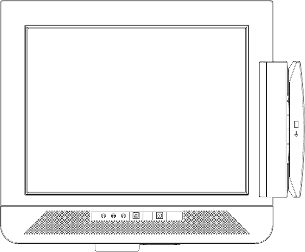
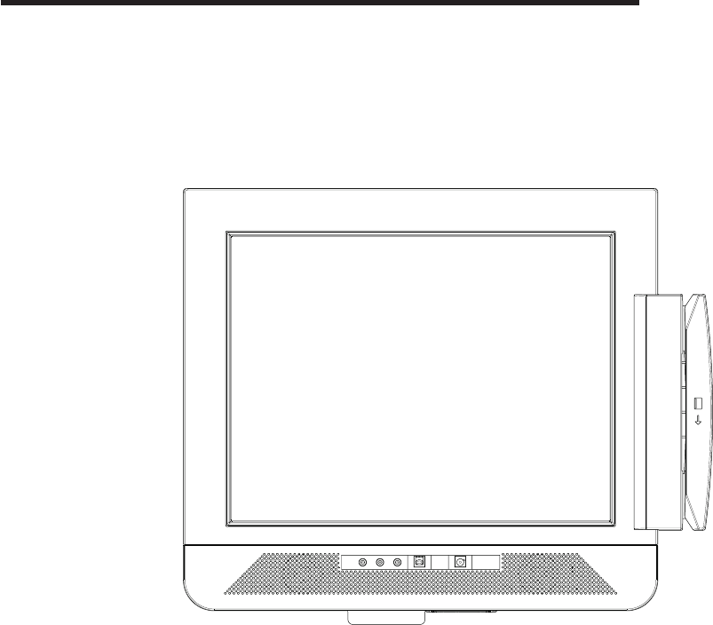
The IBM Anyplace Kiosk (see Figure 1) is a comprehensive and compact, touch
screen terminal for self-service applications. The rugged aspect of the 4836/4838
makes the product suitable for a wide variety of uses, such as retrieving
information, listening to music, or watching multimedia presentations.
To view the model dimensions, see Appendix B, “Product dimensions,” on page 61.
Figure 1. IBM Anyplace Kiosk Model 132
Updated August, 2006
© Copyright IBM Corp. 2006 1

Architecture and attributes
The IBM Anyplace Kiosk uses standard mobile technology within the design of a
customer service terminal. The typical configuration does not contain a keyboard or
mouse because all input is through the touch screen.
The IBM 4836/4838 contains the following key attributes:
v A 12 inch (800 x 600) or 15 inch (1024 x 768) dual-bulb backlit thin film transistor
(TFT) display or a 17 inch (1280 x 1024) quad-bulb backlit TFT display
v Infrared touch-screen system
v Presence detector
v Sealed display face that allows cleaning without the risk of fluids damaging the
chassis
v Intel® Celeron® M Processor 320 (1.3 GHz)
v Intel 855GME mobile chip set
v 2 SO-DIMM DDR memory sockets. Base memory size is 256 Megabytes, with 2
Gigabytes maximum memory.
v External, universal 16 VDC, 120 W power brick. Only use power bricks supplied
by IBM specifically for use with the Anyplace Kiosk.
v Two, 35 mm integrated speakers in specially designed, acoustically ported
enclosures to maximize both the volume and frequency response (except Model
13V)
v Headphone and microphone jack
v Hidden and optionally tamper-proof controls through a snap-on cover for power
on/off, brightness, and contrast
v Ethernet support (10/100 UTP)
v 2 PC USB 2.0 ports for attached input/output (I/O). (Each port can provide
500mA at +5V to external devices). Third party USB hubs can be connected for
additional USB ports.
v 1, 9-pin, non-powered EIA-232 port
v Mounting holes providing 75 x 75 and 100 x 100 mm spacing, which is
compatible with the VESA standard
Note: Power is not provided for any other external devices.
Table 1. Summary of characteristics and weight by model
Characteristics
Model 132, E32, 13V,
W2D
Model 135, E35,
W5D
Model 137, E37,
W7D
Options
Height 295 mm (11.6 in.) 340 mm (13.4 in.) 399 mm (15.7 in.) Scanner: 13 mm (.5
in.)
Width 319 mm (12.5 in.) 383 mm (15.1 in.) 427 mm (16.8 in.) MSR: 45 mm (1.8 in.)
Depth 72 mm (2.8 in.) 72 mm (2.8 in.) 80 mm (3.1 in.) n/a
Weight 4.5 kg (10 lbs.) 5.5 kg (12 lbs.) 7.3 kg (16 lbs.)
Updated August, 2006
2 Anyplace Kiosk 4836/4838
|
|
|
!
!
!
!
!
!
|
|||||
|
|||||
|||||
||||

Models and features
Table 2 describes some of the common 4836/4838 models. Administrative models
and other models that represent different service repair options are not listed. See
your IBM representative for a complete list.
Note: These models do not include the HDD, scanner, or MSR.
Table 2. IBM Anyplace Kiosk models
Model Number Description
Includes depot
maintenance
agreement,
which allows
you to return
the product to
an authorized
IBM repair
center.
Microsoft®
Windows®
Embedded
Point of
Service
preloaded.
Microsoft®
Windows® XP
Professional
for Embedded
Systems
12 inch Models
256 Megabytes
132 x
13V Without speakers.
With volume control.
x
E32 Same as Model 132 x
W2D Same as Model 132 x
15 inch Models
256 Megabytes
135 x
E35 Same as Model 135 x
W5D Same as Model 135 x
17 inch Models
256 Megabytes
137 x
E37 Same as Model 137 x
W7D Same as Model 137 x
Optional features
Table 3. IBM Anyplace Kiosk hardware options
Option Description
Hard disk drive 2.5 in., 40 Gigabyte
Memory Two SO-DIMM DDR memory sockets:
Base memory size is 256 Megabyte,
with 2 Gigabyte maximum memory
MSR ISO 3-track
Updated August, 2006
Chapter 1. Introducing the IBM Anyplace Kiosk 3
!
!
|
|
|
|
|||||
|||||
|||||

Table 3. IBM Anyplace Kiosk hardware options (continued)
Option Description
Bar code scanner Non-laser based, suitable for decoding labels
held up to 5 cm. - 13 cm. (2 in. - 5 in.) away.
Wireless LAN: 802.11 b/g wireless support
through mini-PCI adapter
A factory-only feature.
Note: The wireless solution is certified for
use only in certain countries. See
Appendix C, “Notices,” on page 65.
Configurations
Your sales representative can provide the latest available configurations.
Updated August, 2006
4 Anyplace Kiosk 4836/4838

Mounting options
These are the mounting options for the Anyplace Kiosk:
Wall mount
This mount minimizes protrusion from the wall, but does not have any tilt or
swivel capability.
Table mount
This mount allows the monitor to tilt up and down and rest on a table top.
The screw hole allows you to secure it to the table.
Compatible with VESA standard
This mount is compatible with any third-party mount with 75 x 75 mm or
100 x 100 mm mounting holes.
System software, touch drivers, and diagnostics
The IBM Anyplace Kiosk supports all standard PC-function drivers and provides
interfaces for the following I/O:
Touch screen
v Native mouse emulation
v JavaPOS compatible, OPOS
MSR
v Virtual EIA-232
v JavaPOS, OPOS
Scanner
v Virtual EIA-232
v JavaPOS, OPOS
Presence detector
JavaPOS, OPOS
The MSR and scanners are internally connected using the integrated USB channel.
However, to maximize compatibility with existing applications, the API provided to
applications is a virtual EIA-232 type of interface. For details, see the technical
references available at the IBM Retail Store Solutions Web site.
You can obtain software for your Anyplace Kiosk from the IBM Retail Store
Solutions Web site: http://www.ibm.com/solutions/retail/store/support/.
Supported operating systems
The IBM Anyplace Kiosk supports these operating systems:
v Windows XP, XPe, and 2000
v IBM Retail Store Solutions Linux® (IRES)
Updated August, 2006
Chapter 1. Introducing the IBM Anyplace Kiosk 5

Environmental requirements
Table 4 shows the humidity and temperature limits for the Anyplace Kiosk.
Table 4. Environmental requirements
Temperature (dry
bulb)
Maximum
temperature (wet
bulb) Relative humidity
Operating
5 to 40°C
(41° to 104° F)
27° C
(81° F)
8 to 80%
Power disconnected
0 to 52°C ( 32° to
126° F)
27° C
(81° F)
5 to 95%
Storage
0 to 60°C
(-32° to 140° F)
29° C
(84° F)
5 to 80%
Shipment
-40 to 60°C (-40° to
140° F)
29° C
(84° F)
5 to 100%
Small, variable-speed fans are used for processor and hard drive cooling when
temperatures exceed certain values. Ensure that the cooling vents are not blocked
by papers, signs, or other items.
Power usage
Table 5 shows the power consumption for the Anyplace Kiosk:
Table 5. Power usage
Description Amounts
Power consumption Off: 3W
Heat dissipation: Standby: 18W
On (idle/typical): 50W
On (maximum): 120W
Input voltage and current 100–240 V 50–60 Hz 1.4 A max: Input to power supply
Calling for service
When you call IBM for warranty information or service, be sure to have the following
information available:
v Machine type/model
v Serial number
You can locate this information on the lower-left edge at the rear of the machine.
Updated August, 2006
6 Anyplace Kiosk 4836/4838

Chapter 2. Installing the IBM Anyplace Kiosk
Rear view . . . . . . . . . . . . . . . . . . . . . . . . . . .8
Connectors . . . . . . . . . . . . . . . . . . . . . . . . . . .9
Installation steps . . . . . . . . . . . . . . . . . . . . . . . .10
Opening the cable covers . . . . . . . . . . . . . . . . . . . . .10
Retaining the cables . . . . . . . . . . . . . . . . . . . . . . .11
Installing the options . . . . . . . . . . . . . . . . . . . . . . .12
Installing the scanner . . . . . . . . . . . . . . . . . . . . .12
Installing the MSR (12 inch models) . . . . . . . . . . . . . . . .12
Installing the MSR (15 and 17 inch models) . . . . . . . . . . . . .14
Installing the upgrade options . . . . . . . . . . . . . . . . . . .16
Installing a hard drive . . . . . . . . . . . . . . . . . . . . .16
Installing additional memory . . . . . . . . . . . . . . . . . . .17
Mounting instructions . . . . . . . . . . . . . . . . . . . . . .18
Table-top mount . . . . . . . . . . . . . . . . . . . . . . .18
Wall mount . . . . . . . . . . . . . . . . . . . . . . . . .19
Powering on . . . . . . . . . . . . . . . . . . . . . . . . . .19
Installing the control button cover . . . . . . . . . . . . . . . . .19
This section describes procedures for setting up the Anyplace Kiosk product.
You should be familiar with the rear doors and connectors of the IBM 4836/4838
before you begin the installation steps.
Updated August, 2006
© Copyright IBM Corp. 2006 7
||
||
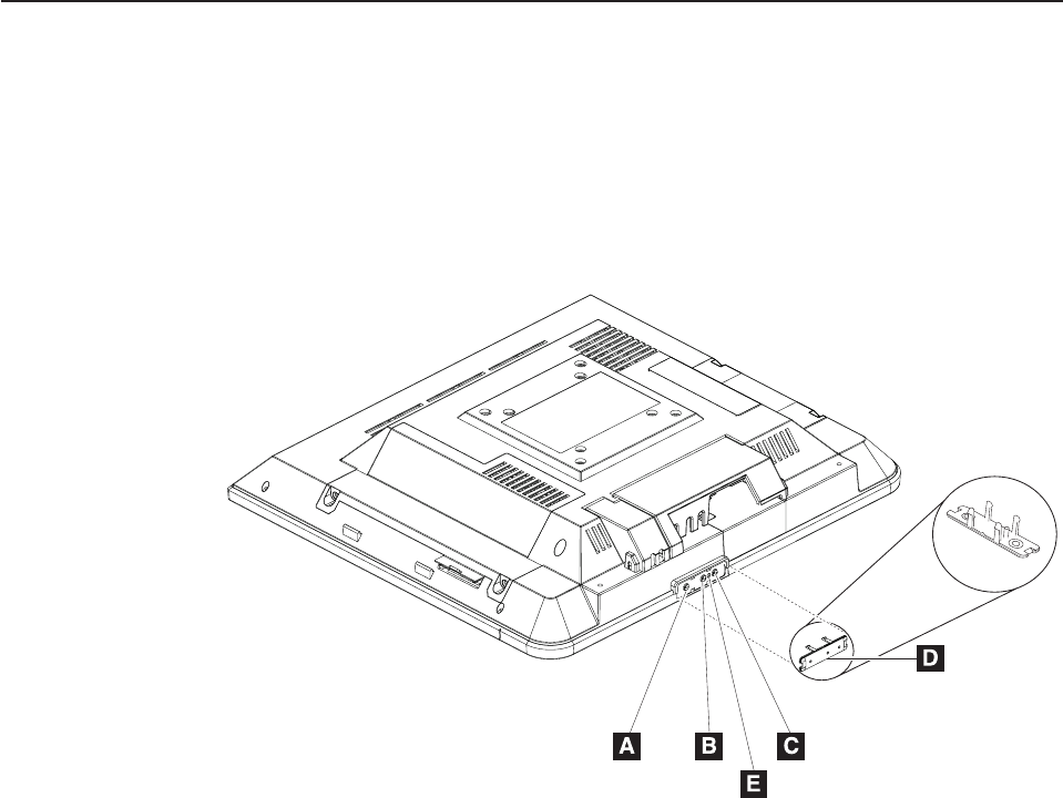
Rear view
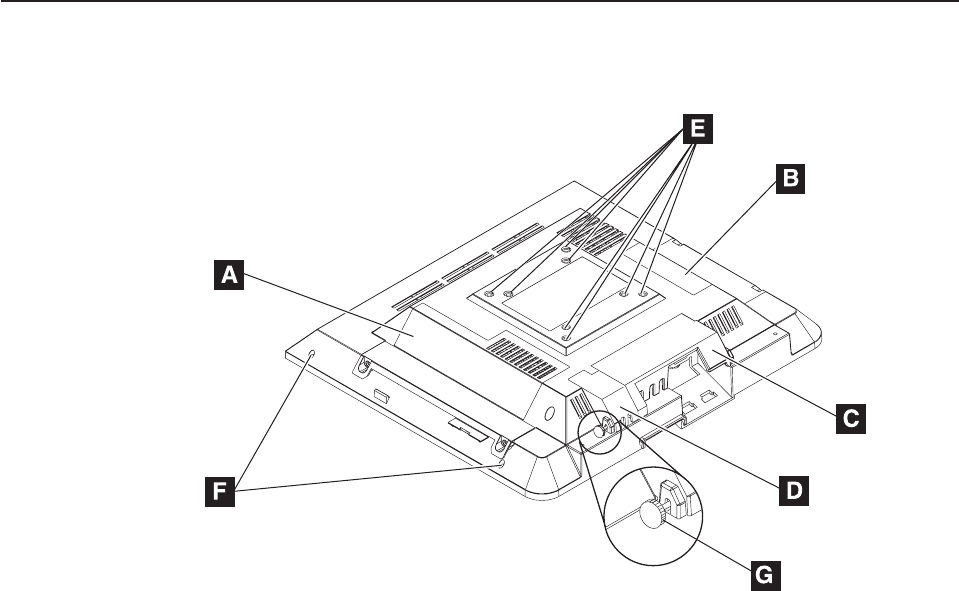
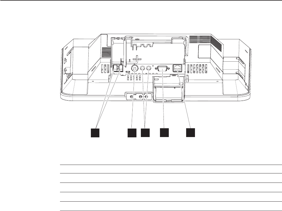
Figure 2 shows the rear view of the IBM 4836/4838.
A Hard drive door
B Memory door
C Cable cover
D USB cover
E Holes that allow for the following standard mounting screws:
v 100 mm x 100 mm (3.93 in. x 3.93 in.)
v 75 mm x 75 mm (2.75 in. x 2.75 in.)
Note: These holes allow for the standard M4 X 10 mm screws specified by
the VESA standard.
F Tapped holes that allow the attachment and display of marques,
announcements, sales promotions and other information.
Note: These holes allow for M3 screws that cannot protrude into the
machine more than 10 mm.
G Close up of cable cover thumbscrews
Figure 2. Rear view showing access doors, mounting holes, attachment holes
Updated August, 2006
8 Anyplace Kiosk 4836/4838

Installation steps
Follow these steps to install the IBM 4836/4838:
1. Install your options (except the MSR).
2. Route, connect and retain the cables. See “Retaining the cables” on page 11.
Be sure to route the cables through the mounting stand before connecting to the
unit.
3. Install the IBM 4836/4838 on your mounting option: table-top (see “Table-top
mount” on page 18) or wall (see “Wall mount” on page 19 or the third-party
mount instructions).
4. Install the optional MSR.
5. Power On the IBM 4836/4838. See “Powering on” on page 19.
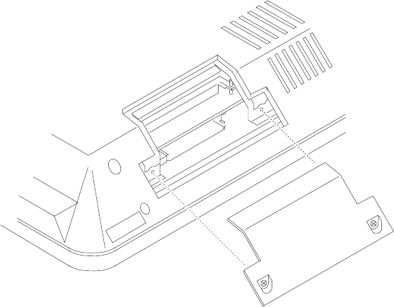
Opening the cable covers
The cable covers provide security and protection to the IBM 4836/4838 cable and
connections.
Note: You can use a screwdriver, if required, during these steps. The USB cover
can be opened independently of the cable cover.
1. Unscrew the USB cover thumbscrew.
2. Unscrew the cable cover thumbscrew.
3. Open both cable covers.
Updated August, 2006
10 Anyplace Kiosk 4836/4838
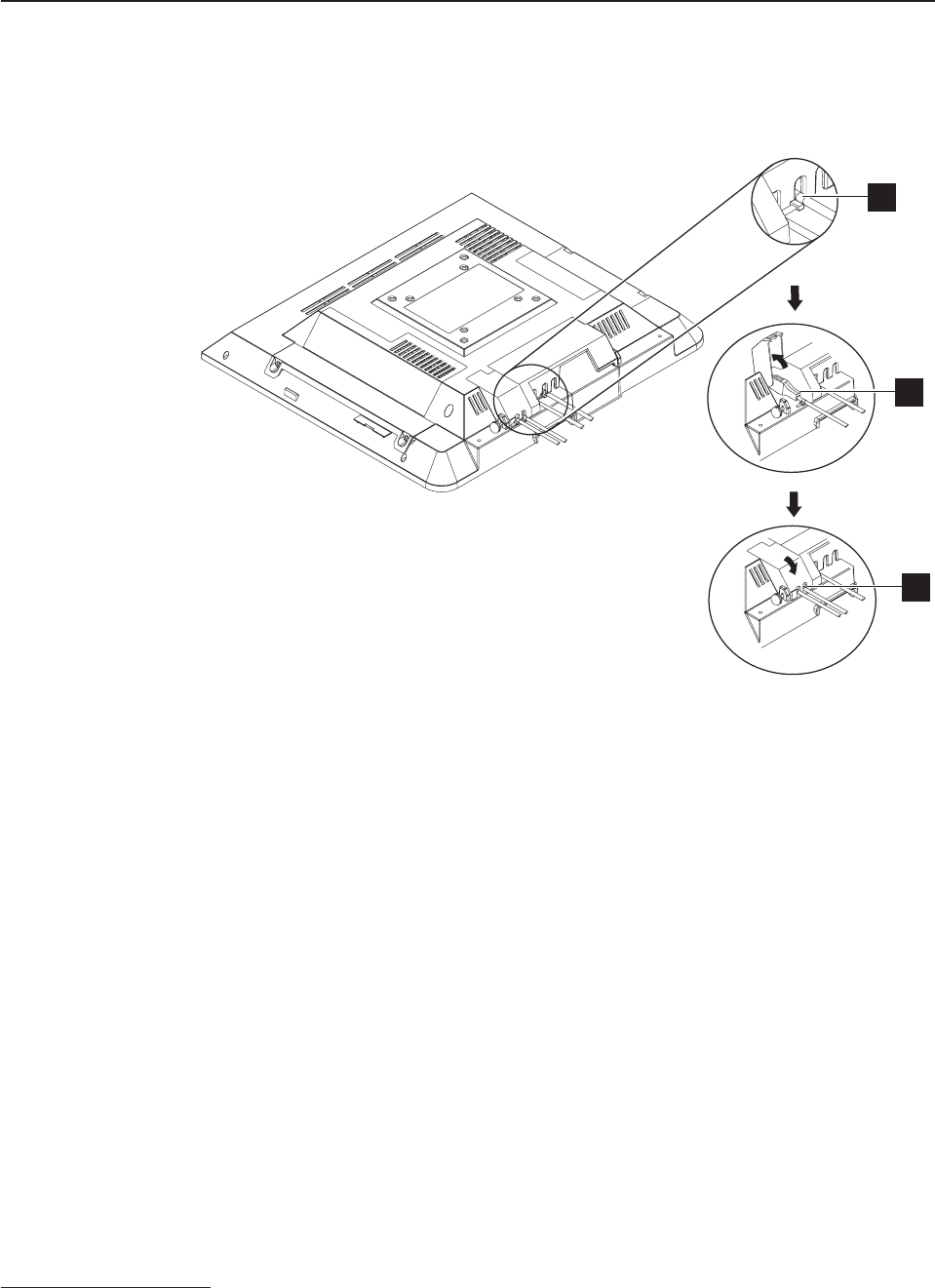
Retaining the cables
The EIA-232 cable is retained to the system unit with screws. The Ethernet cable is
retained by a snap on the connector. When closed, the cable cover retains the
power cable. See Figure 4.
You can retain the audio cables and USB cables by placing cable ties1 on the
outside of the covers. The slots in the cable covers retain the ties. Install the cable
ties as follows:
1. Plug each cable into its respective connector.
2. Install the cable ties to the cable just outside the cable cover as shown in A in
Figure 4.
Note: Ensure that the cable tie is tight and does not move.
3. Open the cable covers (B in Figure 4).
4. Place the cables with the cable ties inside of the cable covers.
5. Close and secure the cable covers with the cable ties inside of the covers (C
in Figure 4).
1. The cable ties are 5 mm (.2 in.) wide.
A
B
C
Figure 4. Retaining the cables using cable ties
Updated August, 2006
Chapter 2. Installing the IBM Anyplace Kiosk 11
Installing the options
The design of the IBM 4836/4838 allows you to install the hard drive, scanner, and
MSR without removing the external cover. Many upgrade features are
factory-installed. See Figure 2 on page 8 to identify the access doors.
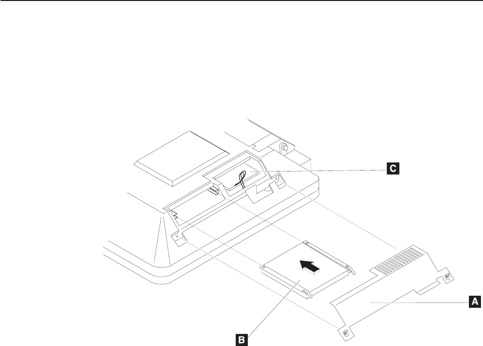
Installing the scanner
1. As shown in Figure 5, place the IBM 4836/4838 face down on a sturdy surface.
2. Lift the cable covers as described in “Opening the cable covers” on page 10.
3. Unfasten the screw (A) holding the scanner bay cover (B). Discard the
cover, but retain the screw for step 6.
4. Connect the scanner cable (C) to the connector (E).
5. Align the tabs (D) on the scanner with the adjacent slots on the cover and
slide into position.
6. Secure in place by inserting the screw (A).
Note: For best scanning results, hold the object to be scanned 2 to 4 inches away
from the scanner.
Note: For EIA-232 modes, the scanner may need to be configured. Refer to the
IBM Knowledge Base at the IBM Retail Store Solutions Web site
(http://www.ibm.com/store/support/) for details on configuring the scanner.
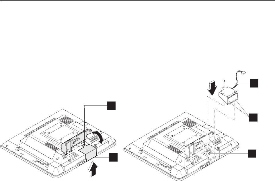
Installing the MSR (12 inch models)
Note: Install the MSR after you mount the IBM 4836/4838. See “Mounting
instructions” on page 18.
1. Remove the hard drive door by unfastening the two screws located on the door
and discard.
2. With the IBM 4836/4838 mounted onto the desired stand, locate the mounting
features for the MSR on the right side of the machine.
3. Align the MSR such that the connectors are slightly above their matching slots
on the 4836/4838. The ground strap should lie in the top of the rear cover
C
D
A
BE
Figure 5. Installing the scanner
Updated August, 2006
12 Anyplace Kiosk 4836/4838
|
|
|
|
|
|
|
|
|
opening. Slide the MSR downward into position, being careful not to pinch the
MSR cable. The ground strap should be on top of the main shield flange. See
1 in Figure 6.
4. Plug the USB cable into the connector. See 2 in Figure 6.
5. Install the hard drive door with MSR latching tab and secure the two screws.
See 3 in Figure 6.
1
2
3
Figure 6. Installing the MSR (12 inch models)
Updated August, 2006
Chapter 2. Installing the IBM Anyplace Kiosk 13
|
|
|
|
|
|
|
|
|
|
|
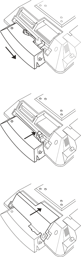
Installing the MSR (15 and 17 inch models)
Note: Install the MSR after you mount the IBM 4836/4838. See “Mounting
instructions” on page 18.
1. Remove the hard drive door by unfastening the two screws located on the door
and discard.
2. With the IBM 4836/4838 mounted onto the desired stand, locate the mounting
features for the MSR on the right side of the machine.
3. Align the MSR such that the connectors are slightly above their matching slots
on the 4836/4838. The ground strap should lie in the top of the rear cover
opening. Slide the MSR downward into position, being careful not to pinch the
MSR cable. The ground strap should slide under the pressure clip. See 1 in
Figure 7 on page 15.
Updated August, 2006
14 Anyplace Kiosk 4836/4838
|
|
|
|
|
|
|
|
|
|
|
|
|
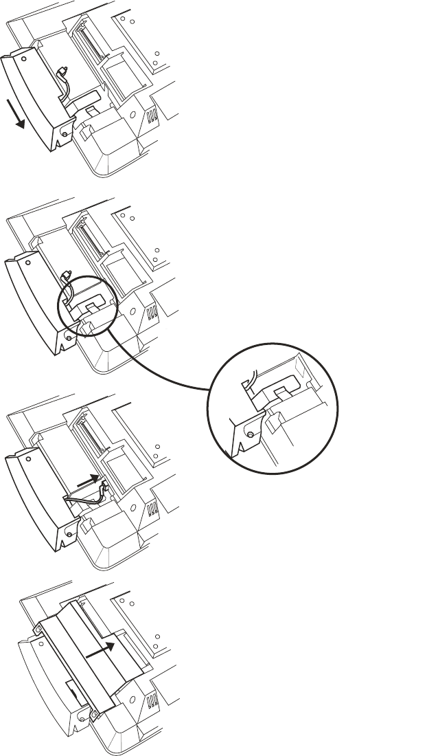
4. Slide the grounding strap under the grounding clip. See 2 in Figure 7.
5. Plug the USB cable into the connector. See 3 in Figure 7.
6. Install the hard drive door with MSR latching tab and secure the two screws.
See 4 in Figure 7.
1
2
3
4
Figure 7. Installing the MSR (15 and 17 inch models)
Updated August, 2006
Chapter 2. Installing the IBM Anyplace Kiosk 15
|
|
|
|
|
|
|
|
Installing the upgrade options
Note: Most internal upgrade options are ordered and arrive pre-installed. This
section is provided for technical personnel only.
Installing a hard drive
See Figure 2 on page 8 to identify the hard drive access door.
1. Place the IBM 4836/4838 face down on a sturdy surface.
2. Unfasten the two captured screws to remove the HDD door (A). See Figure 8.
3. Locate the slot and brackets and insert the hard drive (B).
Note: Note the optional wireless card (C). If ordered, this card is installed at the
factory. For removal and replacement procedures, see“Removing the
wireless card” on page 33.
Figure 8. Removing the hard drive cover
Updated August, 2006
16 Anyplace Kiosk 4836/4838
Installing additional memory
To install additional memory, refer to Figure 2 on page 8. This figure identifies the
memory access door.
1. Place the 4836/4838 face down on a sturdy surface.
2. See Figure 9. Remove the two captured screws on each side of the memory
door and pull to remove.
3. Insert the memory card into the brackets at an angle with the connector end
down.
4. Rotate the outer edge of the memory card downward until it snaps into place.
Note: You must remove the back cover if you are replacing both memory modules.
Figure 9. Installing additional memory
Updated August, 2006
Chapter 2. Installing the IBM Anyplace Kiosk 17
Mounting instructions
You can choose between a table-top, wall mount, or a third party mount.
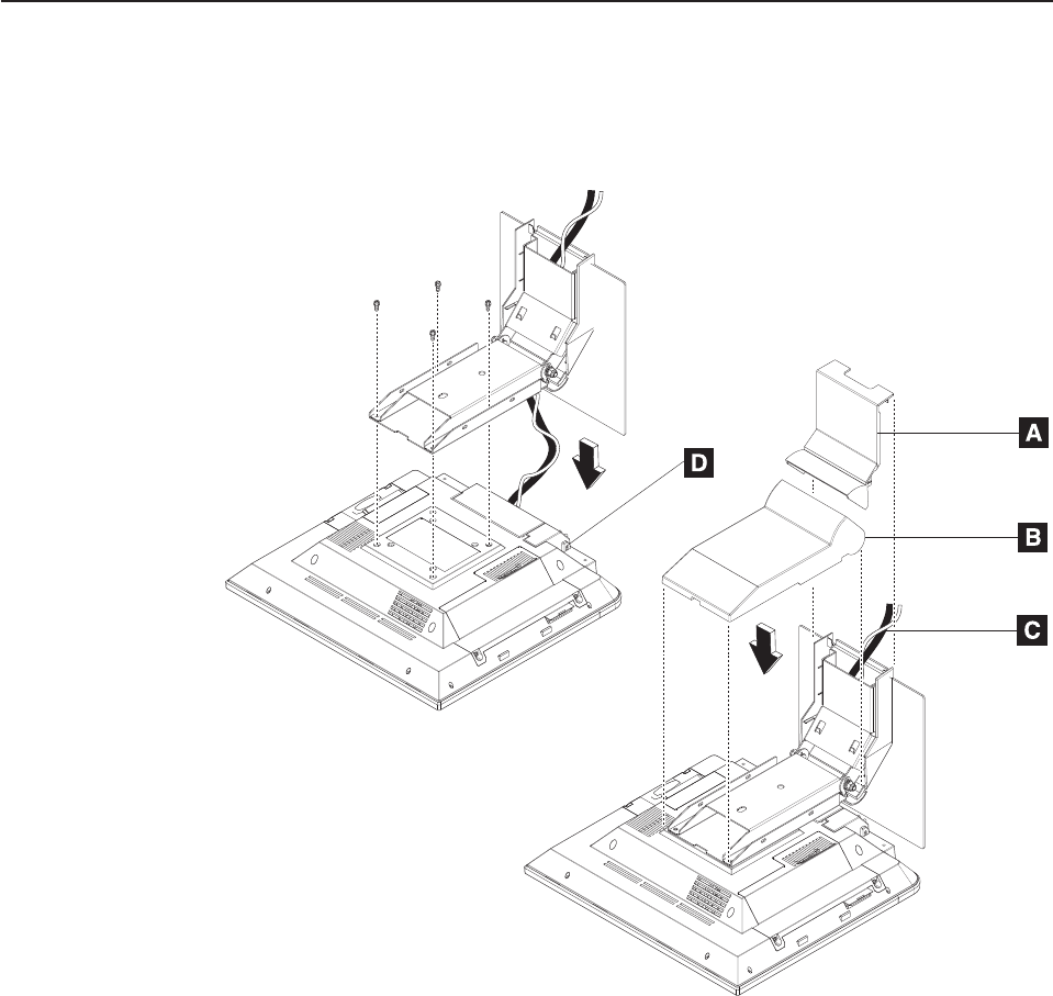
Table-top mount
CAUTION:
The illustration above shows the table-top mount for a 12 inch or 15 inch
model. The 17 inch models (137, E37) use a different table-top mount than the
one shown above (see “Assembly 4: Table-top stand and wall mount” on page
58), though the instructions below are the same. Do not attempt to mount a
17 inch model onto the table-top mount for a 12 inch or 15 inch model.
1. Remove the base cover (A) and arm cover (B).
2. Route and connect the cables (C) to the IBM 4836/4838.
3. Close cable cover and tighten thumbscrew (D) on the cover.
4. Close USB cover (optional).
5. Attach the mount to the unit with the four screws.
6. Install the base cover (A) and the arm cover (B).
7. Place the IBM 4836/4838 unit in the desired location and retain the cables (see
“Retaining the cables” on page 11).
Figure 10. Installing table-top mount
Updated August, 2006
18 Anyplace Kiosk 4836/4838
Note: You can bolt the unit to the counter top, using the hole provided in the
mount.
Wall mount
Follow the procedures described in Chapter 3, “Mounting the IBM Anyplace Kiosk to
the wall,” on page 21.
Powering on
Notes:
1. Your new IBM 4836/4838 ships with a control cover. If you want the buttons
covered, install this part after you power on and adjust the image.
2. A small hole (E in Figure 11) under the control cover allows you access to the
reset switch. Use a paperclip or other small tool to activate the switch.
3. A screwdriver is required to pry off the cover.
1. Plug the power adapter into the 4836/4838.
2. Plug the power adapter into an electrical outlet.
3. Power on the IBM 4836/4838 using the power switch (see A in Figure 11). The
4836/4838 power light-emitting diode (LED) will initially appear green.
4. To adjust the brightness, select the plus + (B) or minus - (C) keys.
Installing the control button cover
See Figure 11. To install the control button cover (D), follow these steps:
1. Match the alignment pins on the button cover with the hole between the buttons.
2. Snap into place.
Figure 11. IBM 4836/4838 controls and installing the control cover
Updated August, 2006
Chapter 2. Installing the IBM Anyplace Kiosk 19
Updated August, 2006
20 Anyplace Kiosk 4836/4838
Chapter 3. Mounting the IBM Anyplace Kiosk to the wall
Follow these procedures to mount the IBM 4836/4838 to the wall.
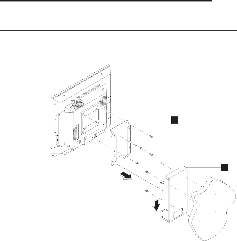
Mounting the wall mount plate
The mounting adapter A is secured to a metal wall-mount plate B, which can be
installed on wood, drywall surface over studs, or a solid concrete or brick wall.
Wall mounting requirements
Note: Before mounting the wall mount plate, ensure that you are following all
applicable building and electric codes.
When mounting, ensure that you have enough room for adequate viewing,
ventilation, and access to an AC power outlet. The method of mounting must be
able to support the combined weight of the IBM 4836/4838 plus the suspended
weight of all the cables to be attached to the system. Use the following methods for
mounting your system:
A
B
Figure 12. System and wall mount plate
Updated August, 2006
© Copyright IBM Corp. 2006 21
Mounting to hollow walls
v Method 1: Wood surface – A minimum wood thickness—38 mm (1.5 in.) by 28
cm (11 in.)—of high, construction-grade wood is recommended.
Note: This method provides the most reliable attachment of the unit with little
risk that the unit will come loose or require ongoing maintenance.
v Method 2: Drywall walls – Drywall over wood studs is acceptable.
Mounting to a solid concrete or brick wall – Mounts on a flat smooth surface.
Selecting the location
Plan the mounting location thoroughly. Locations such as walkway areas, hallways,
and crowded areas are not recommended. Mount the unit to a flat, sturdy,
structurally sound column or wall surface.
The best mounting surface is a standard countertop, cabinet, table, or other
structure that is minimally the width and length of the unit. This recommendation
reduces the risk that someone may accidentally walk into and damage the device.
Local laws governing the safety of individuals might require this type of
consideration.
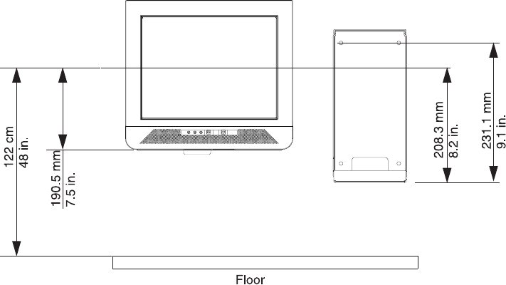
Determining the mounting height of wall mount plate
For users in a standing position, the typical height is approximately 122 cm (48 in.)
from the floor to the center of the touch display. The height used should be
appropriate and comfortable for a large portion of the users. Additionally, you should
adjust the display’s initial angle of tilt to provide adequate and comfortable viewing
by the users for the tasks that they perform.
Figure 13. IBM 4836/4838 mounting height
Updated August, 2006
22 Anyplace Kiosk 4836/4838
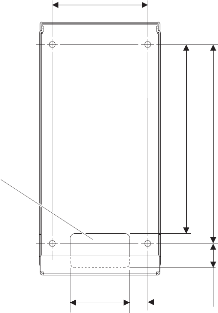
Wall mount plate mounting options
The wall mount plate and wall cutout dimensions are shown in Figure 14. The I/O
and power cables for the unit can be routed either through the wall behind the unit,
or out the bottom of the rear cover.
Note: Wall mount plate is not drawn to scale.
Attaching the wall mount plate
CAUTION:
The wall mount plate must be installed by an insured, qualified, professional
installer who is familiar with building construction methods, building
materials, building codes, electrical codes, fire codes, and local laws
governing public access areas.
It is imperative that the wall mount plate is attached securely and permanently to
the wall. The 4836/4838 weighs approximately 6.4 kg (14 lb.), and its weight is
centered approximately 75 mm (3 in.) away from the wall. In addition to this weight,
the wall mount plate must maintain secure and permanent attachment in the event
the unit is knocked, bumped, or otherwise abused. If the wall mount plate is not
securely attached to the wall, the unit might fall and be damaged, and may cause
injury to others.
98 mm
(3.87 in)
186.6 mm
(7.37 in)
200 mm
(7.87 in)
35 mm
(1.37 in)
60 mm
(2.37 in)
18 mm
(0.75 in)
Cable
Exit
Figure 14. Wall mount plate and wall cutout dimensions
Updated August, 2006
Chapter 3. Mounting the IBM Anyplace Kiosk to the wall 23
There is a wide variation of types of wall construction, age and condition. After
reviewing the conditions on site, the installer must make the final judgment as to the
suitability of the existing wall material to determine if additional bracing or supports
are required.
Attaching the wall mount plate involves making minor modifications to the building
construction. Be sure to observe proper safety precautions to prevent injury.
Unforeseen hazards, for example, natural gas and power lines, can exist when
drilling and cutting into walls.
Note: Compliance with local building codes, electrical codes and the governing
laws should take precedence over this set of instructions.
Fasteners are not included with the unit, and must be supplied by the installer. The
types of fasteners required are dependent on the type of wall construction. See
“Fastener types” on page 27 for detailed descriptions and pictures of the fasteners
discussed below. If the recommended size is not available, choose the next longer
or larger size. Choose fasteners that are rated either ”Medium Duty“ or ”Heavy
Duty.“ To assure proper fastener selection and installation, follow the fastener
manufacturer’s recommendations.
Mounting to hollow walls
Hollow walls include walls that are constructed of drywall board that is securely
fastened to wood studs. The studs must make up the main structure and strength of
the wall.
Method 1: Wood surface
Use this method if construction changes to the wall are permitted. This method will
provide the most reliable attachment of the unit to the wall with little risk that the
unit will ever come loose or require ongoing maintenance.
The drywall board is removed in an area approximately 30 cm (12 in.) high that
spans the space between two studs. The two wood studs can be cut back
approximately 38 mm (1.5 in.) by 28 cm (11 in.) high. A 38 mm (1.5 in.) thick by 28
cm (11 in.) high construction grade wood support is attached to the two wall studs
with six lag screws as shown in Table 7 on page 25. Install the Lag Screws directly
into the center of the studs without pre-drilling a hole. Do not use soap or other
lubricant on the screws during installation. The wood support material should be
either solid wood or plywood. After installation of the support, you can replace and
prepare the drywall board for final finishing.
Updated August, 2006
24 Anyplace Kiosk 4836/4838
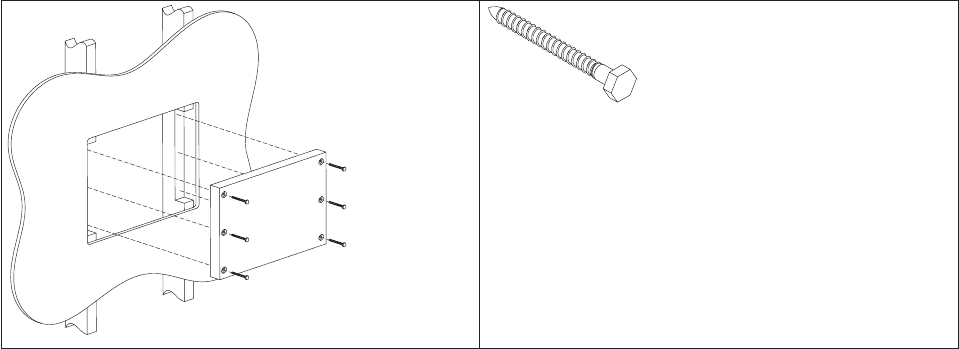
Table 7. Securing the wood support to the wood studs using lag screws
Lag screw
Screw size: 6.3 mm (0.25 in.) or nominal thread
diameter
Length: 60 mm (2.5 in.) minimum
Use a bubble level to assure that the wall mount plate is mounted squarely. Use six
wood screws to attach the wall mount plate to the wall. Center the wall mount plate
vertically on the wood support. Install the wood screws directly into the wood
support without pre-drilling a hole. Do not use soap or other lubricant on the screws
during installation. See “Fastener types” on page 27 for more information.
After installation, make sure that the screw heads are flush or below the outer
surface of the wall mount plate. Check to make sure that you firmly and securely
attach the wall mount plate to the wall.
Method 2: Drywall surface
Use this method if you cannot make construction changes to the wall. This method
provides a safe attachment of the unit to the wall. However, there is risk that the
wall mount plate and unit might become loose if it is struck with a high force. The
drywall must be at least 12.7 mm (0.5 in.) thick to use this method. Use a bubble
level to assure that you mount the wall mount plate squarely.
Install two ″Medium Duty″ or ″Heavy Duty″ fasteners. Use fasteners, which are
designed for drywall, in one side of the wall mounting plate B, as shown in
Table 8 on page 26. Depending on the type of fastener, portions of the fastener may
need to be installed into the wall first. You may possibly thread them through the
screw holes in the wall mount plate. The recommended types of drywall fasteners
are: self-drilling drywall anchor, hollow wall anchor, toggle bolt, self-drilling drywall
toggle bolt, and plastic toggle bolt. Use two wood screws A, as shown in Table 8
on page 26, to attach the wall mount plate to the stud. Install the Wood Screws
directly into the center of the stud without pre-drilling a hole. Do not use soap or
other lubricant on the screws during installation. See “Fastener types” on page 27
fastener descriptions and pictures at the end of this section for more information.
Updated August, 2006
Chapter 3. Mounting the IBM Anyplace Kiosk to the wall 25
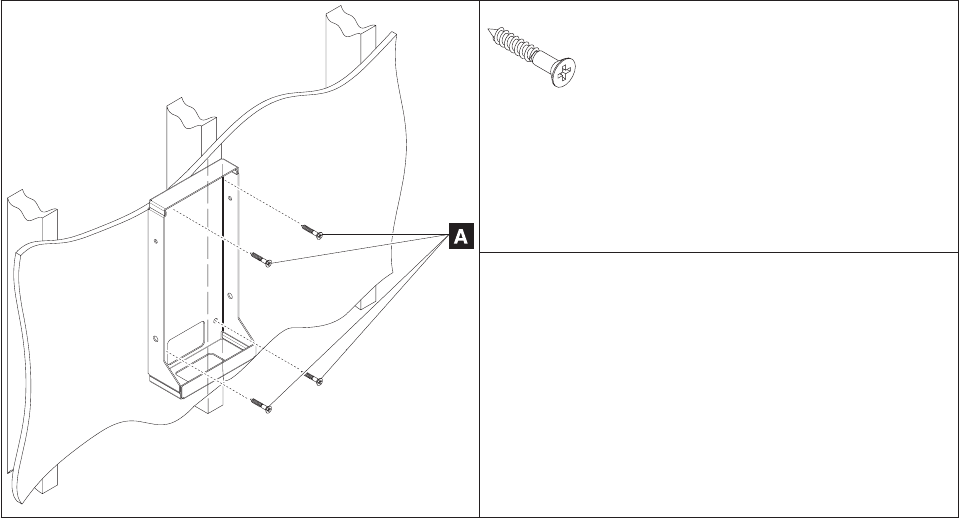
Table 8. Securing the wall mounting plate to a drywall surface. This figure shows wood screws (A); however, other
types of screws (B) can be used.
A
Wood screw
Size: #12 or 5.5 mm nominal thread diameter
Length: 38 mm (1.5 in.) minimum
Note: May be installed on either the right or left side.
B
v Self-drilling drywall anchor
v Hollow wall anchor
v Toggle bolt
v Plastic toggle bolt
v Self-drilling drywall toggle bolt
See Table 9 on page 27 for additional descriptions.
After installation, make sure the screw heads are flush or below the outer surface of
the wall mount plate. Check to make sure you firmly and securely attach the wall
mount plate to the wall.
Mounting to a concrete or brick wall
This mounting surface includes walls that are constructed of either brick wall and
mortar or solid concrete.
Due to the variable nature of laying bricks, and the variation in types of mortar
joints, most brick walls have an uneven surface. If possible, select a location on the
wall that allows all four corner screw holes to remain flat without warping the wall
mount plate. If this location is not possible, add a metal washer or other type of
shim under one or more screw holes. This addition allows the wall mount plate to
be mounted without warping it.
Use a bubble level to assure that you mount the wall mount plate squarely. Use
four concrete anchors to attach the wall mount plate to the wall. Use one concrete
anchor in each corner of the wall mount plate. See “Fastener types” on page 27 for
detailed fastener information to determine the types of fasteners that are suggested.
After installation, make sure that the screw heads are flush or below the outer
surface of the wall mount plate. Check to make sure that you attached the wall
mount plate firmly and securely to the wall.
Updated August, 2006
26 Anyplace Kiosk 4836/4838
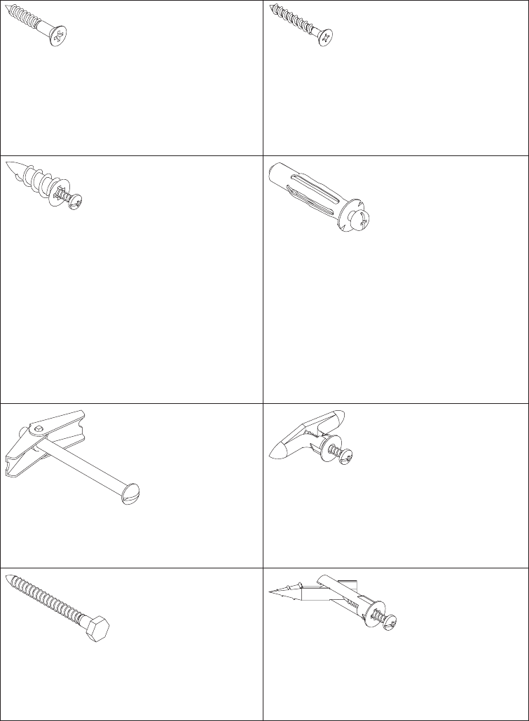
Fastener types
Table 9 lists the different fasteners that you can use to mount the wall mount plate.
The fasteners are not drawn to actual size.
Table 9. Fastener types
Wood screw
Size: #12 or 5.5 mm nominal thread
diameter
Length: 38 mm (1.5 in.) minimum
Concrete Anchor
Size: 5 mm (3/16 in.) nominal thread
diameter
Length: 32 mm (1.25 in.) minimum
Note: Fastener has a high/low
thread that cuts its own threads.
Self-Drilling Drywall Anchor
Screw size: #8 or 4 mm nominal
thread diameter
Types: E-Z Anchor 50# (22 kg)
pullout rating or Cobra WallDriller
Hollow Wall Anchor
Screw size: 5 mm (3/16 in.) nominal
thread diameter
Note: Metal casing size is
dependent on wall board thickness.
During installation, grip head of
metal casing with pliers when
initially tightening the screw to flare
the legs. "No drill" or "drive" types
are not recommended.
Toggle Bolt
Screw size: 5 mm (3/16 in.) nominal
thread diameter
Plastic Toggle Bolt
Screw size: #8 or 4 mm nominal
thread diameter
Note: Toggle size is dependent on
wall board thickness.
Lag Screw
Screw size: 6.3 mm (1/4-in.) or
nominal thread diameter
Length: 2.5 in. or 60 mm minimum
Self-Drilling Drywall Toggle Bolt
Screw size: #8 or 4-mm nominal
thread diameter
Updated August, 2006
Chapter 3. Mounting the IBM Anyplace Kiosk to the wall 27
Updated August, 2006
28 Anyplace Kiosk 4836/4838

Chapter 4. Removing and replacing FRUs
Reviewing the IBM 4836/4838 assembly . . . . . . . . . . . . . . .30
Before you begin . . . . . . . . . . . . . . . . . . . . . . .30
Removing the back cover . . . . . . . . . . . . . . . . . . . . .31
Removing the scanner and scanner window . . . . . . . . . . . . . .31
Removing the cable covers . . . . . . . . . . . . . . . . . . . .32
Removing the main shield . . . . . . . . . . . . . . . . . . . . .32
Removing the wireless card . . . . . . . . . . . . . . . . . . . .33
Locating and resetting the CMOS jumper . . . . . . . . . . . . . . .34
Removing the memory card . . . . . . . . . . . . . . . . . . . .34
Removing the hard drive fan . . . . . . . . . . . . . . . . . . . .35
Changing the battery . . . . . . . . . . . . . . . . . . . . . . .36
Removing the heat sink . . . . . . . . . . . . . . . . . . . . . .37
Removing the processor . . . . . . . . . . . . . . . . . . . . .38
Removing the hard disk drive and bracket . . . . . . . . . . . . . . .38
Removing the speakers . . . . . . . . . . . . . . . . . . . . . .39
Removing the system board . . . . . . . . . . . . . . . . . . . .40
Removing the control card . . . . . . . . . . . . . . . . . . . . .41
Removing the control buttons . . . . . . . . . . . . . . . . . .41
Removing the front panel card . . . . . . . . . . . . . . . . . . .42
Removing the backlight inverter card . . . . . . . . . . . . . . . . .43
Removing the LCD . . . . . . . . . . . . . . . . . . . . . . .44
Replacing the front bezel . . . . . . . . . . . . . . . . . . . . .46
Removing the mounting stand cover set . . . . . . . . . . . . . . .47
Removing the volume control card (Model 13V only) . . . . . . . . . . .48
Note: Procedures in this section should be performed by qualified service
personnel.
Updated August, 2006
© Copyright IBM Corp. 2006 29
Updated August, 2006
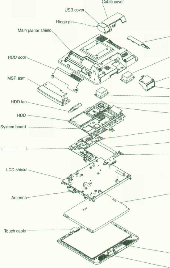
Reviewing the IBM 4836/4838 assembly
Figure 15 summarizes the field replaceable parts of the IBM 4836/4838 assembly.
The part number associated with each FRU is located in Appendix A,
"Field-replaceable units."
Backlight inverter card
Memory door
Speaker
•Scanner asm
Scanner window
Speaker
•Heatsink
Memory
Front panel card
Control panel cable
•Control panel card
LCD display
Front bezel with
touch system
Control buttons
Figure 15. Exploded view of the IBM 4836/4838 assembly
Before you begin
Always practice safety first. Before removing the back cover (or performing any
removal procedures), follow these steps;
1. Turn off power.
2. Remove the power cable.
3. Place the unit on a sturdy surface.
30 Anyplace Kiosk 4836/4838
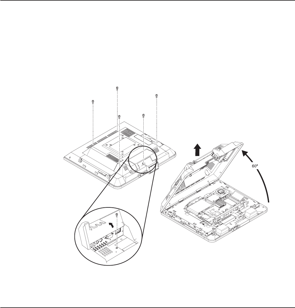
Removing the back cover
Follow these steps to remove the back cover:
1. Place the IBM 4836/4838 face down on a sturdy surface.
2. If installed, remove the MSR and scanner.
3. If installed, remove the button cover by prying under one end with a small
screwdriver.
4. Locate and unfasten the five captured screws (see Figure 16) that secure the
back cover.
5. Lift the cover to approximately a 60° angle (see Figure 16) to release the hooks
and reveal the main planar assembly.
Removing the scanner and scanner window
To remove the scanner, reverse the steps described in “Installing the scanner” on
page 12.
To remove the scanner window:
1. Using a small screwdriver, pry out the scanner window.
2. To replace, place the window in the correct position and snap into place.
Figure 16. Removing the back covers
Updated August, 2006
Chapter 4. Removing and replacing FRUs 31
Removing the cable covers
Follow these steps to remove and replace the cable covers:
1. Open the covers as described in “Opening the cable covers” on page 10.
2. Remove the hinge pin (see Figure 15 on page 30) and lift to remove the covers.
3. To replace, reverse these steps.
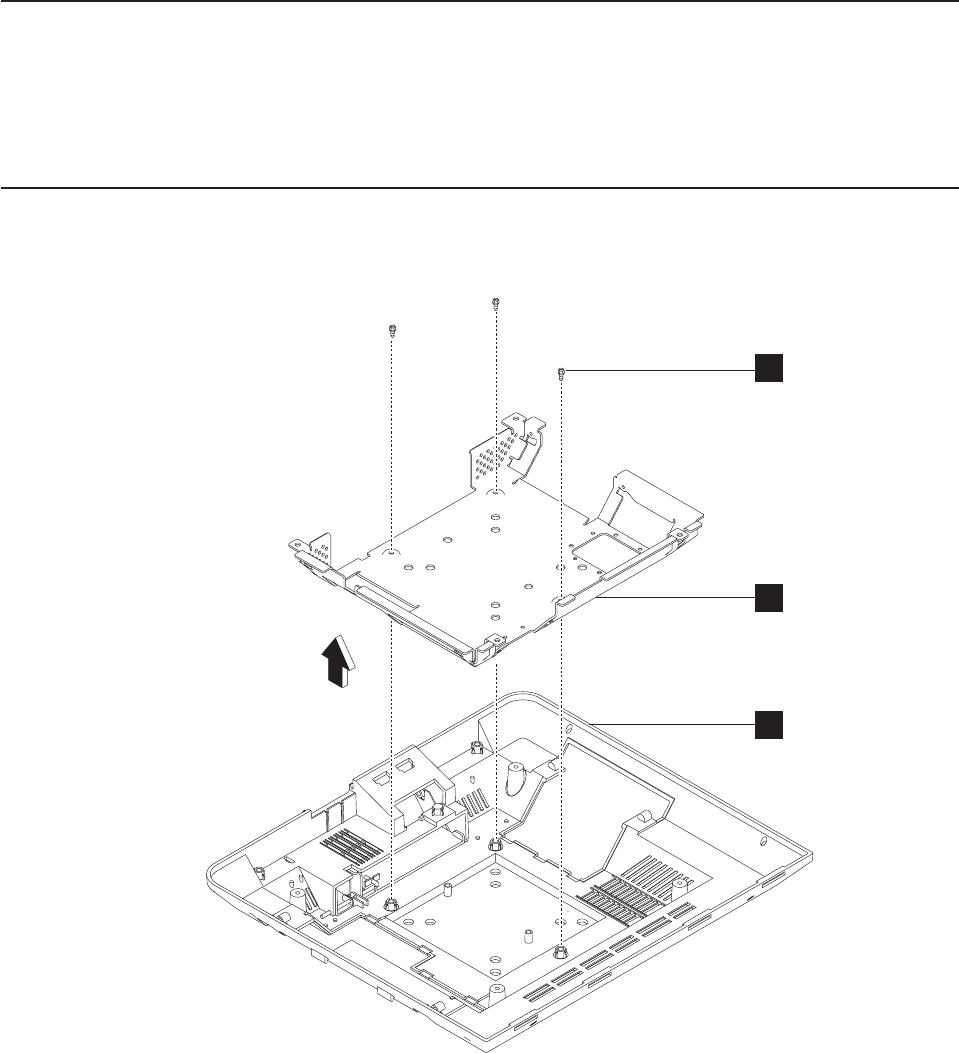
Removing the main shield
1. Remove the cover as described in “Removing the back cover” on page 31.
2. See Figure 17 and locate the main shield (B) that is attached to the back
cover (C).
3. Remove the three screws (A) that hold the shield and lift to remove.
4. To replace, reverse this procedure.
A
B
C
Figure 17. Removing the main shield
Updated August, 2006
32 Anyplace Kiosk 4836/4838

Removing the wireless card
Removal and replacement procedure for the wireless card (for service personnel
only), are included in hard copy format with the wireless card FRU.
Updated August, 2006
Chapter 4. Removing and replacing FRUs 33
|
|
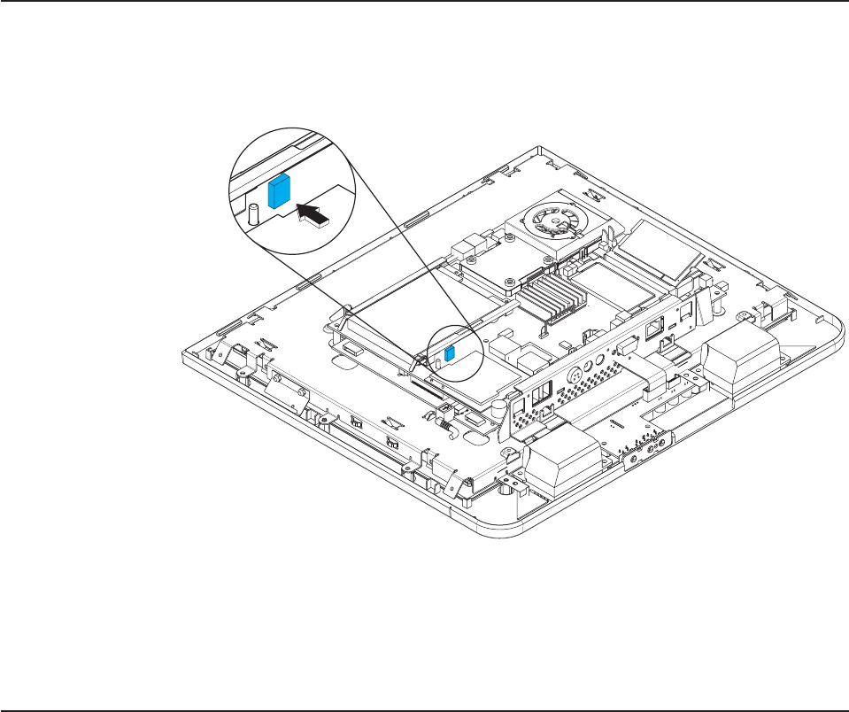
Locating and resetting the CMOS jumper
Follow these steps to locate and reset the CMOS jumper:
1. Remove the cover as described in “Removing the back cover” on page 31.
2. Locate the blue CMOS jumper on the main planar assembly. See Figure 18.
The jumper is located near the hard drive and beside the radio card.
3. Remove the jumper from the board and wait several seconds.
4. Reinstall jumper to reset defaults.
Removing the memory card
To remove the optional memory card, reverse the steps listed in “Installing
additional memory” on page 17. To remove the factory-installed memory, follow
these steps:
1. Remove the back cover as described in “Removing the back cover” on page 31.
2. Remove the memory card from its slot.
3. To replace the memory card, reverse these steps.
Figure 18. Location of the CMOS jumper
Updated August, 2006
34 Anyplace Kiosk 4836/4838
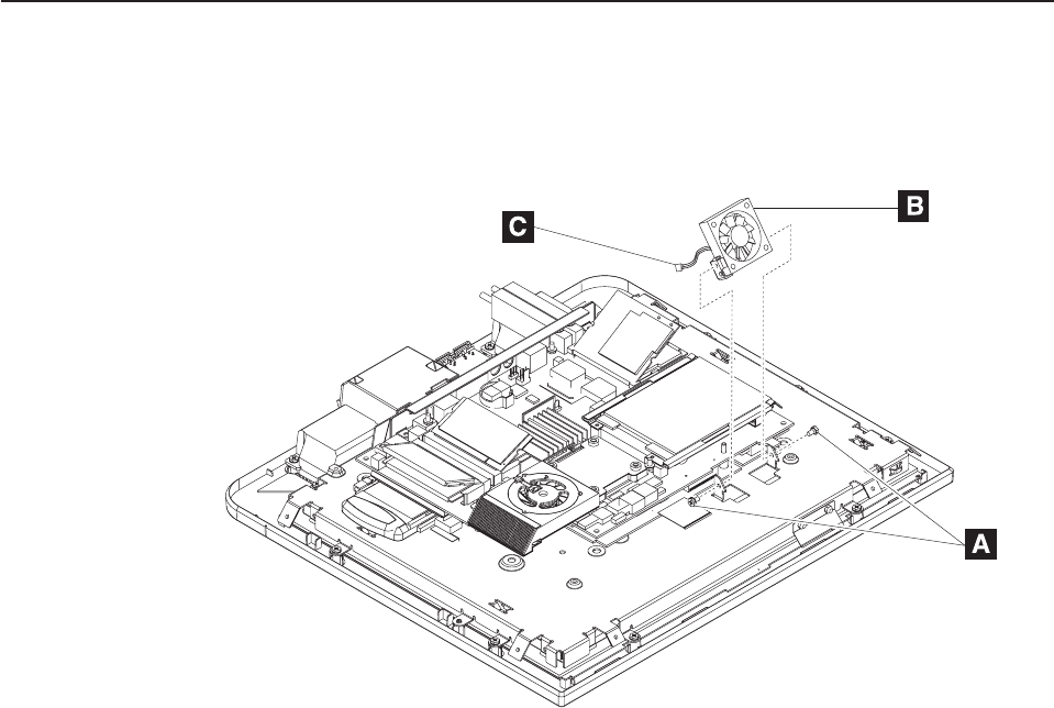
Removing the hard drive fan
To remove and replace the hard drive fan, follow these steps:
1. Remove the back cover as described in “Removing the back cover” on page 31.
2. Detach the fan connector (C in Figure 19) from the system board.
3. Using a Phillips screwdriver, remove the two screws located on each side of the
hard drive fan (A in Figure 19).
4. Lift the fan (B) from its housing.
5. To replace the hard drive fan, arrange the notches on the fan brackets under
the hooks of the mounting tabs. Then rotate the fan into place.
6. Replace the two screws.
7. Plug the fan connector (C) back into the system board.
Figure 19. Removing the hard drive fan
Updated August, 2006
Chapter 4. Removing and replacing FRUs 35
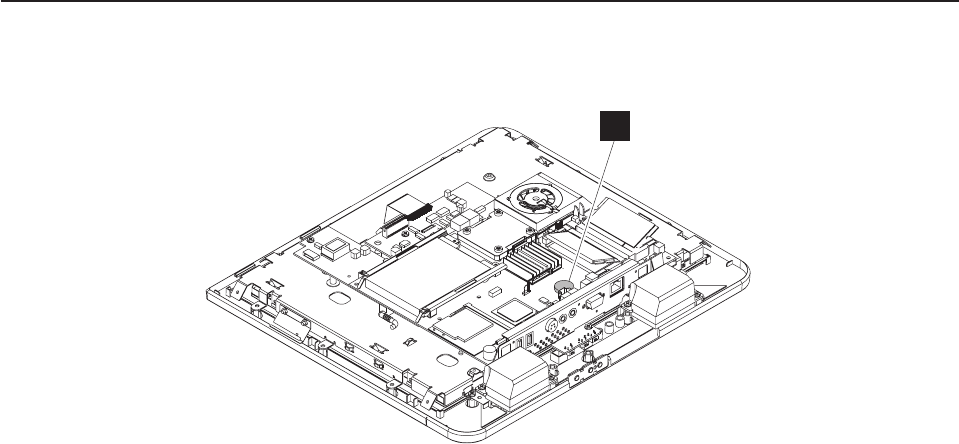
Changing the battery
1. Remove the back cover as described in “Removing the back cover” on page 31.
2. Locate the battery on the main planar assembly (B in Figure 20).
3. Using your finger, press on one of the tabs holding the coin battery, and the
battery pops out.
4. To replace the battery, align the battery underneath the tabs and press down.
B
Figure 20. View of battery and heatsink
Updated August, 2006
36 Anyplace Kiosk 4836/4838