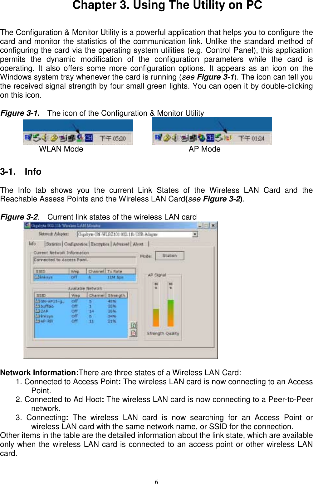
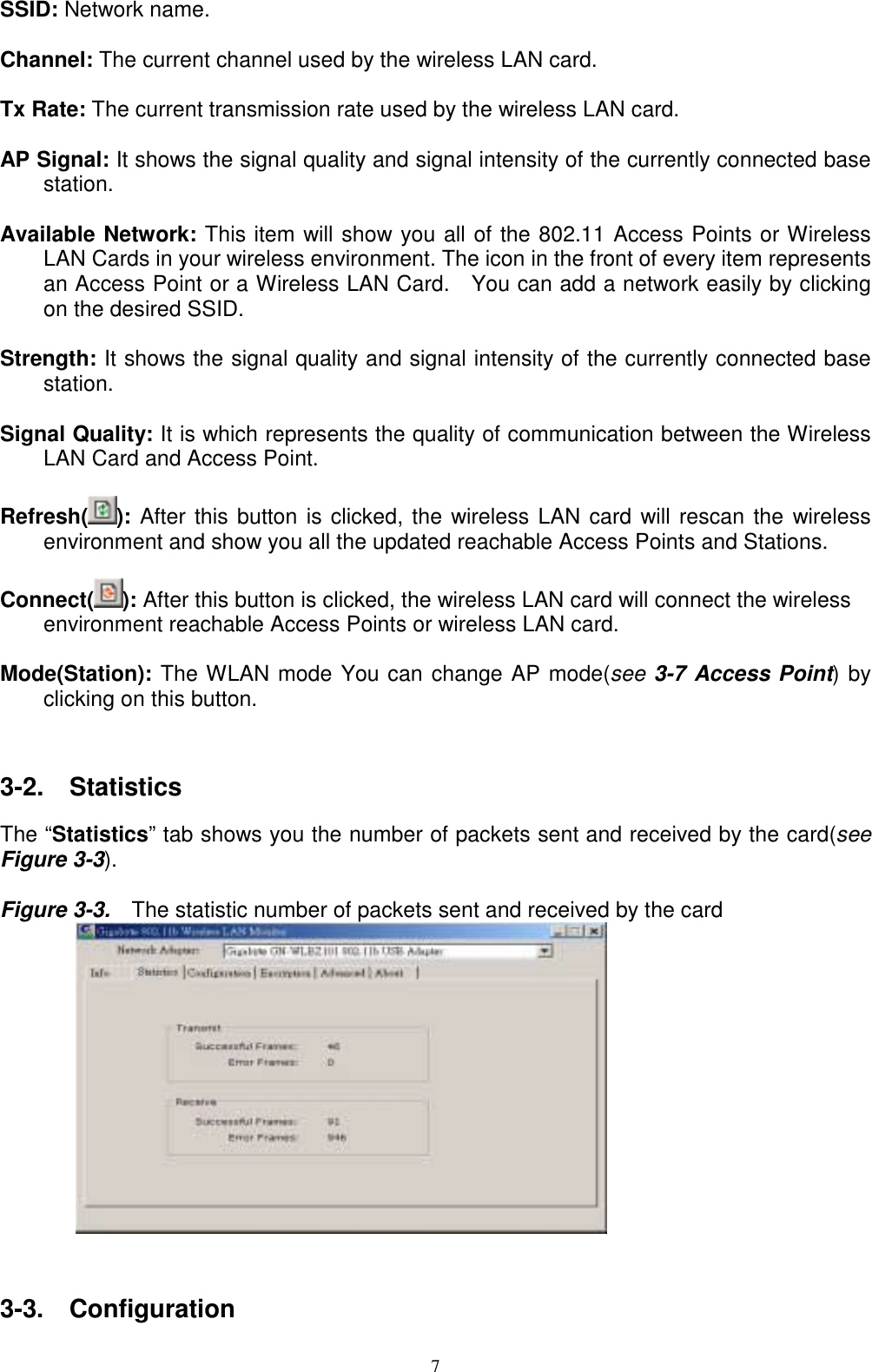
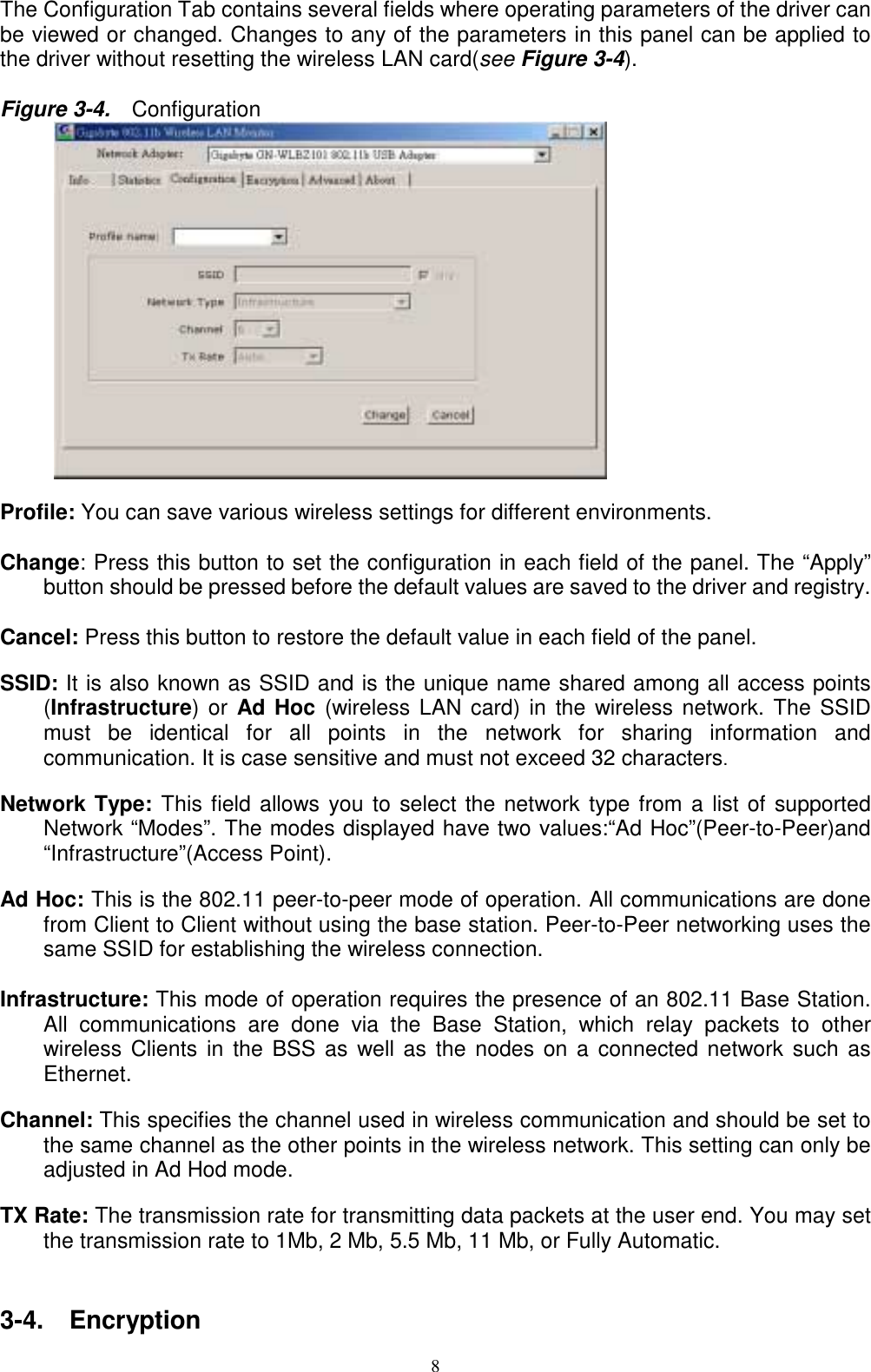
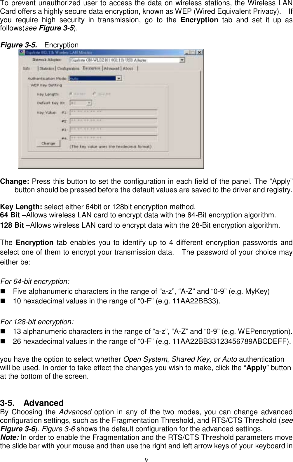
GIGA BYTE TECHNOLOGY GN-WLBZ201 IEEE 802.11b USB STICK Storage/Wireless LAN User Manual Manual revised

GIGA-BYTE TECHNOLOGY CO., LTD. IEEE 802.11b USB STICK Storage/Wireless LAN Manual revised

Manual revised

                                GN-WLBZ201IEEE 802.11b USB STICK Storage/Wireless LANCardUser’s Manual                                                http://www.gigabyte.com.twRev. 1.0 First Edition
Federal Communication Commission Interference StatementThis equipment has been tested and found to comply with the limits for a Class B digitaldevice, pursuant to Part 15 of the FCC Rules. These limits are designed to providereasonable protection against harmful interference in a residential installation. Thisequipment generates, uses and can radiate radio frequency energy and, if not installed andused in accordance with the instructions, may cause harmful interference to radiocommunications. However, there is no guarantee that interference will not occur in aparticular installation. If this equipment does cause harmful interference to radio ortelevision reception, which can be determined by turning the equipment off and on, the useris encouraged to try to correct the interference by one of the following measures:- Reorient or relocate the receiving antenna.- Increase the separation between the equipment and receiver.- Connect the equipment into an outlet on a circuit different from that to which the receiveris connected.- Consult the dealer or an experienced radio/TV technician for help.FCC Caution: any changes or modifications not expressly approved by the partyresponsible for compliance could void the user’s authority to operate this equipment.This device complies with Part 15 of the FCC Rules. Operation is subject to the followingtwo conditions: (1) This device may not cause harmful interference, and (2) this devicemust accept any interference received, including interference that may cause undesiredoperation.IMPORTANT NOTE:FCC Radiation Exposure Statement:This equipment complies with FCC radiation exposure limits set forth for an uncontrolledenvironment.This device complies with FCC RF Exposure limits set forth for an uncontrolledenvironment, under 47 CFR 2.1093 paragraph (d)(2).This transmitter must not be co-located or operating in conjunction with any other antennaor transmitter.
                                       ContentsCHAPTER 1. PRODUCT OVERVIEW 11-1. INTRODUCTION TO THE WIRELESS LAN CARD............................................................. 11-2. FEATURES................................................................................................................. 11-3. PHYSICAL DIMENSIONS/PACKAGING............................................................................ 11-4. LED INDICATING LIGHTS............................................................................................ 11-5. SYSTEM REQUIREMENTS............................................................................................ 21-6. WRITE-PROPECT FUNCTION....................................................................................... 2CHAPTER 2. INSTALLING THE WIRELESS LAN CARD 42-1. INSTALLING THE DRIVER & UTILITY FOR PC................................................................. 4CHAPTER 3. USING THE UTILITY ON PC 63-1.  INFO........................................................................................................................ 63-2.  STATISTICS.............................................................................................................. 73-3.  CONFIGURATION....................................................................................................... 73-4.  ENCRYPTION............................................................................................................ 83-5.  ADVANCED............................................................................................................... 93-6.  ABOUT................................................................................................................... 103-7.  ACCESS POINT (SUPPORTED UNDER WINDOWS XP).................................................. 103-8.  BRIDGE SETUP (SUPPORTED UNDER WINDOWS XP).................................................. 123-9.  IP SHARING (SUPPORTED UNDER WINDOWS 2000)................................................... 14CHAPTER 4. SPECIFICATION 16
1Chapter 1. Product Overview1-1.  Introduction to The Wireless LAN CardWLBZ201 is designed for product differentiation with 32M/64M/128M Bytes Flash memoryfor data backup。This wireless Local Area Network (LAN) card is composed of the IEEE802.11b MAC with USB STICK interface、Baseband、radio components and two built-inantennas。This product adopts the direct sequence spread spectrum (DSSS) technologyusing the DBPSK、DQPSK、and CCK modulations to provide a very stable wirelesscommunication quality and an excellent signal receiver capability。This product features the compact size、low power consumption and power managementfunctions and provides a high-speed wireless data communication。Therefore this productis ideally suitable for being integrated into the personal mobile and handheld platform。1-2. Features!  Flash Memory 32Mbytes /64Mbytes /128Mbytes.!  Two dimenional rotation of maximum 180 degree!  Conforms to IEEE 802.11b specification.!  Transmits data rate up to the maximum speed of 11Mbps.!  Dynamically scales the data rate to 11, 5.5, 2, and 1Mbps.!  Host Interface USB.! Built-in diversity antenna.!  Supports 64-bit /128-bit WEP encryption.!  Driver supports Windows 98SE/Me/2000/XP.!  Free Software Access Point.1-3. Physical Dimensions/PackagingDimensions: 126mm* 25mm* 16mmBefore the installation procedures, please ensure the components are not damaged duringthe shipping. The shipment of the GN-WLBZ201 includes:One GN-WLBZ201 Wireless LAN CardOne Installation CD (including User’s Guide and Driver)One User GuidePlease contact your local distributor or authorized reseller immediately for any missing ordamaged components. If you require returning the damaged product, you must pack it inthe original packing material or the warranty will be voided.1-4.  LED Indicating LightsThis wireless LAN card conforms to the USB standard. There are six LED-indicating lights
2One indicates R/W status. One indicates Link status and the others indicate the intensity ofreceived signals.  R/W::  This LED is blinks quickly when the card is flash memory Read or Write.****To prevent data loss and/or damage to WLAN Card, never remove WLAN Card from theUSB port while data is transferring.  Link:Blinking Slow   The card is scanning the network.Continuously On   The card is successfully connected to a network.Blinking Quickly   The data is being transmitted/received    LED Light   Condition R/W Link  Intensity of received signals:  This LED specifies the four conditions of “POOR”,“FAIR”, “GOOD”, and “EXCELLENT” .    LED Light     Condition of theReceiver POOR FAIR GOOD EXCELLENT1-5. System Requirements1-5-1. Supported Platform:       IBM PC/AT compatible computer1-5-2. Supported Operation System:      Windows 98SE/Me/2000/XP1-5-3. Software Access Point Supported Operation System:      Windows 2000/XP1-6. Write-Propect FunctionWhen the Write-Protect switch is set to Unlocked “ ”, you can read/write data
3from/into Flash Memory. When the Write-Protect switch is set to Locked “ ”, youcan’t write data into Flash Memory or format it. You can only read data fromFlash Memory. Please set the switch to Unlocked “” before format.
4Chapter 2. Installing the Wireless LAN Card2-1.  Installing The Driver & Utility for PCStep 1: Please make sure that you don’t plug your card yet.Step 2: Execute the setup.exe on our CD, and then the following window will pop up.Click “Install Wireless LAN Driver”.Step 3: Click “Yes”.Step 4: Please plug-in your “Gigabyte WLAN card device” ! and will install the device driverClick “Yes”, and then your installation is ok.
5
6Chapter 3. Using The Utility on PCThe Configuration & Monitor Utility is a powerful application that helps you to configure thecard and monitor the statistics of the communication link. Unlike the standard method ofconfiguring the card via the operating system utilities (e.g. Control Panel), this applicationpermits the dynamic modification of the configuration parameters while the card isoperating. It also offers some more configuration options. It appears as an icon on theWindows system tray whenever the card is running (see Figure 3-1). The icon can tell youthe received signal strength by four small green lights. You can open it by double-clickingon this icon.Figure 3-1.    The icon of the Configuration & Monitor Utility             WLAN Mode                           AP Mode3-1.  InfoThe Info tab shows you the current Link States of the Wireless LAN Card and theReachable Assess Points and the Wireless LAN Card(see Figure 3-2).Figure 3-2.  Current link states of the wireless LAN card      Network Information:There are three states of a Wireless LAN Card:1. Connected to Access Point: The wireless LAN card is now connecting to an AccessPoint.2. Connected to Ad Hoct: The wireless LAN card is now connecting to a Peer-to-Peernetwork.3. Connecting: The wireless LAN card is now searching for an Access Point orwireless LAN card with the same network name, or SSID for the connection.Other items in the table are the detailed information about the link state, which are availableonly when the wireless LAN card is connected to an access point or other wireless LANcard.
7SSID: Network name.Channel: The current channel used by the wireless LAN card.Tx Rate: The current transmission rate used by the wireless LAN card.AP Signal: It shows the signal quality and signal intensity of the currently connected basestation.Available Network: This item will show you all of the 802.11 Access Points or WirelessLAN Cards in your wireless environment. The icon in the front of every item representsan Access Point or a Wireless LAN Card.  You can add a network easily by clickingon the desired SSID.Strength: It shows the signal quality and signal intensity of the currently connected basestation.Signal Quality: It is which represents the quality of communication between the WirelessLAN Card and Access Point.Refresh( ): After this button is clicked, the wireless LAN card will rescan the wirelessenvironment and show you all the updated reachable Access Points and Stations.Connect( ): After this button is clicked, the wireless LAN card will connect the wirelessenvironment reachable Access Points or wireless LAN card.Mode(Station): The WLAN mode You can change AP mode(see 3-7 Access Point) byclicking on this button.3-2.  StatisticsThe “Statistics” tab shows you the number of packets sent and received by the card(seeFigure 3-3).Figure 3-3.    The statistic number of packets sent and received by the card       3-3.  Configuration
8The Configuration Tab contains several fields where operating parameters of the driver canbe viewed or changed. Changes to any of the parameters in this panel can be applied tothe driver without resetting the wireless LAN card(see Figure 3-4).Figure 3-4.    Configuration      Profile: You can save various wireless settings for different environments.Change: Press this button to set the configuration in each field of the panel. The “Apply”button should be pressed before the default values are saved to the driver and registry.Cancel: Press this button to restore the default value in each field of the panel.SSID: It is also known as SSID and is the unique name shared among all access points(Infrastructure) or Ad Hoc (wireless LAN card) in the wireless network. The SSIDmust be identical for all points in the network for sharing information andcommunication. It is case sensitive and must not exceed 32 characters.Network Type: This field allows you to select the network type from a list of supportedNetwork “Modes”. The modes displayed have two values:“Ad Hoc”(Peer-to-Peer)and“Infrastructure”(Access Point).Ad Hoc: This is the 802.11 peer-to-peer mode of operation. All communications are donefrom Client to Client without using the base station. Peer-to-Peer networking uses thesame SSID for establishing the wireless connection.Infrastructure: This mode of operation requires the presence of an 802.11 Base Station.All communications are done via the Base Station, which relay packets to otherwireless Clients in the BSS as well as the nodes on a connected network such asEthernet.Channel: This specifies the channel used in wireless communication and should be set tothe same channel as the other points in the wireless network. This setting can only beadjusted in Ad Hod mode.TX Rate: The transmission rate for transmitting data packets at the user end. You may setthe transmission rate to 1Mb, 2 Mb, 5.5 Mb, 11 Mb, or Fully Automatic.3-4.  Encryption
9To prevent unauthorized user to access the data on wireless stations, the Wireless LANCard offers a highly secure data encryption, known as WEP (Wired Equivalent Privacy).    Ifyou require high security in transmission, go to the Encryption  tab and set it up asfollows(see Figure 3-5).Figure 3-5.    Encryption     Change: Press this button to set the configuration in each field of the panel. The “Apply”button should be pressed before the default values are saved to the driver and registry.Key Length: select either 64bit or 128bit encryption method.64 Bit –Allows wireless LAN card to encrypt data with the 64-Bit encryption algorithm.128 Bit –Allows wireless LAN card to encrypt data with the 28-Bit encryption algorithm.The Encryption tab enables you to identify up to 4 different encryption passwords andselect one of them to encrypt your transmission data.    The password of your choice mayeither be:For 64-bit encryption:!  Five alphanumeric characters in the range of “a-z”, “A-Z” and “0-9” (e.g. MyKey)!  10 hexadecimal values in the range of “0-F” (e.g. 11AA22BB33).For 128-bit encryption:!  13 alphanumeric characters in the range of “a-z”, “A-Z” and “0-9” (e.g. WEPencryption).!  26 hexadecimal values in the range of “0-F” (e.g. 11AA22BB33123456789ABCDEFF).you have the option to select whether Open System, Shared Key, or Auto authenticationwill be used. In order to take effect the changes you wish to make, click the “Apply” buttonat the bottom of the screen.3-5.  AdvancedBy Choosing the Advanced  option in any of the two modes, you can change advancedconfiguration settings, such as the Fragmentation Threshold, and RTS/CTS Threshold (seeFigure 3-6). Figure 3-6 shows the default configuration for the advanced settings.Note: In order to enable the Fragmentation and the RTS/CTS Threshold parameters movethe slide bar with your mouse and then use the right and left arrow keys of your keyboard in
10order to select an exact number.Figure 3-6.    Advanced settings     3-6.  AboutBy choosing this option, you can view basic information about the utility like the Driver,Firmware and Application Version and this adapter’s MAC address(see Figure 3-7).Figure 3-7.    Version information and MAC address     3-7.  Access Point (Supported under Windows XP)The Info tab shows you the current Link States of the Assess Points and the Wireless LANCard (see Figure 3-8).
11Figure 3-8.  Current link states of the Access Point Mode      Access Point: The AP mode You can change WLAN mode(see 3-1 Info) by clicking onthis button.More Setting: You can set the configuration Access Point(see Figure 3-9) by clicking onthis button.WEP(ON/OFF): You can using WEP (Wired Equivalent Privacy) by clicking on this button.Figure 3-9.  configuration of the Access Point Mode      Change: Press this button to setting the default value in each field of the panel. The “Apply”button should be pressed before the default values are saved to the driver and registry.Channel: The current channel used by the Access Point.Basic Rate: The transmission rate for transmitting data packets at the user end. You mayset the transmission rate to 1Mb, 2 Mb, 5.5 Mb, 11 Mb.SSID: Network name.
12Hide SSID: Access Point disable their SSID broadcasting to prevent a wireless device fromfinding and accessing their networks.Tx Power: Transmitter Output power.MAC Address Filter: You can set the configuration MAC Address Filter(see Figure 3-10)by clicking on this button.Figure 3-10.  MAC Address Filter      Filter Type: There are three status of a Access Point:1. Disable: The Filter MAC Address function disable.2.  Accept: The Filter MAC Address (wireless LAN card) can connect to a AccessPoint.3.  Reject: The Filter MAC Address (wireless LAN card) can’t connect to a AccessPoint.3-8.  Bridge Setup (Supported under Windows XP)Step 1: Change to AP mode (see Figure 3-8).Step 2: 「Control Panel」run「Network Connections」 (see Figure 3-11).
13Figure 3-11.   Control Panel      Step 3: Setup Wireless LAN card(see Figure 3-12), Click ”Use Windows to configure” tocancel the schedule and Click「OK」.Figure 3-12.  Wireless Networks      Step 4::::  Select the network connections to be bridged. Press the 「「「「Ctrl」」」」  key while clickingthe network connection icons to select. Right-click on any selected network icon.Select  「「「「Bridge Connections」」」」(see Figure 3-13).Show Network Bridge(see Figure 3-14).
14Figure 3-13.  Bridge Connections      Figure 3-14.  Network Bridge      Step 5:::: Setup OK,Show Network Bridge windows(see Figure 3-15) and then your setupis ok.Figure 3-15.  Network Bridge Enabled      3-9.  IP Sharing (Supported under Windows 2000)Step 1: Change to AP mode (see Figure 3-8).Step 2: 「Control Panel」run「Network and Dial-up Connections」 (see Figure 3-16).
15Figure 3-16.   Control Panel      Step 3: Setup LAN card(see Figure 3-17), Click ”Enable Internet Connection Sharing forthis connection” and Click「OK」.Figure 3-17.  Local Area Connection Properties      Step 4::::  Show Local Network(see Figure 3-18). Click「「「「OK」」」」  and then your setup is ok.Figure 3-18.  Local Network
16Chapter 4. SpecificationSystemFlash Memory 32Mbytes /64Mbytes /128MbytesStandards IEEE 802.11b compliantHost Interface USB1.1Modulation 1Mbps: DBPSK; 2Mbps: DQPSK; 5.5 and 11 Mbps: CCKData Rate 1, 2, 5.5, 11 MbpsOperating Voltage 5VPower Tx 340mA; Rx 300 mA; Sleep 90 mAOperating Range Outdoor: 100 - 300m; Indoor: 30 - 100mRFFrequency Band 2.400 ~ 2.484 GHz (subject to local regulation)Radio Technology DSSS (Direct Sequence Spread Spectrum)11 Channels (US, Canada) 4 channels (France)Number of Channel 14 Channels (Japan) 13 Channels (Most European countries, ETSI)Peak Output power 16dBm@ Nominal Temp RangeReceive Sensitivity - 80dBm @ 11 Mbps date rate, 8% PERAntenna one built-in Chip antennaRegulatory and Environmental ComplianceFCC part 15 (USA) DGT (Taiwan)EMC certification CE  (Europe) TELEC (Japan)Temperature Range Operating: 0 ~ 50 degree C, Storage: -20 ~ 65 degree CHumidity Max. 90% Non-condensingSoftwareDriver Windows 98SE/ME/2000/XPRoaming Full mobility and seamless roamingAP Function Supported under Windows 2000/XPSecurity 64 and 128 bit WEPManagement Utility Monitors the network situation.MechanicalDimensions 126mm * 25mm * 16mmWeight 27 ± 1 gPackaging Generic, Gigabyte, private labeling optionalLED indicators Read/Write ,Link and intensity of received signalsNote: The specifications are subject to change without noticeGIGABYTE declares that GN-WLBZ201 (IEEE 802.11b USB STICK Storage /Wireless LAN Card ) ( FCC ID: JCK-GN-WLBZ201 ) is limited in CH1~CH11by specified firmware controlled in USA.

Navigation menu