GIGA BYTE TECHNOLOGY GN-WLBZ201 IEEE 802.11b USB STICK Storage/Wireless LAN User Manual Manual revised
GIGA-BYTE TECHNOLOGY CO., LTD. IEEE 802.11b USB STICK Storage/Wireless LAN Manual revised
Manual revised

GN-WLBZ201
IEEE 802.11b USB STICK Storage/Wireless LAN
Card
User’s Manual
http://www.gigabyte.com.tw
Rev. 1.0 First Edition
Federal Communication Commission Interference Statement
This equipment has been tested and found to comply with the limits for a Class B digital
device, pursuant to Part 15 of the FCC Rules. These limits are designed to provide
reasonable protection against harmful interference in a residential installation. This
equipment generates, uses and can radiate radio frequency energy and, if not installed and
used in accordance with the instructions, may cause harmful interference to radio
communications. However, there is no guarantee that interference will not occur in a
particular installation. If this equipment does cause harmful interference to radio or
television reception, which can be determined by turning the equipment off and on, the user
is encouraged to try to correct the interference by one of the following measures:
- Reorient or relocate the receiving antenna.
- Increase the separation between the equipment and receiver.
- Connect the equipment into an outlet on a circuit different from that to which the receiver
is connected.
- Consult the dealer or an experienced radio/TV technician for help.
FCC Caution: any changes or modifications not expressly approved by the party
responsible for compliance could void the user’s authority to operate this equipment.
This device complies with Part 15 of the FCC Rules. Operation is subject to the following
two conditions: (1) This device may not cause harmful interference, and (2) this device
must accept any interference received, including interference that may cause undesired
operation.
IMPORTANT NOTE:
FCC Radiation Exposure Statement:
This equipment complies with FCC radiation exposure limits set forth for an uncontrolled
environment.
This device complies with FCC RF Exposure limits set forth for an uncontrolled
environment, under 47 CFR 2.1093 paragraph (d)(2).
This transmitter must not be co-located or operating in conjunction with any other antenna
or transmitter.

Contents
CHAPTER 1. PRODUCT OVERVIEW 1
1-1. I
NTRODUCTION TO
T
HE
W
IRELESS
LAN C
ARD
............................................................. 1
1-2. F
EATURES
................................................................................................................. 1
1-3. P
HYSICAL
D
IMENSIONS
/P
ACKAGING
............................................................................ 1
1-4. LED I
NDICATING
L
IGHTS
............................................................................................ 1
1-5. S
YSTEM
R
EQUIREMENTS
............................................................................................ 2
1-6. W
RITE
-P
ROPECT
F
UNCTION
....................................................................................... 2
CHAPTER 2. INSTALLING THE WIRELESS LAN CARD 4
2-1. I
NSTALLING
T
HE
D
RIVER
& U
TILITY FOR
PC................................................................. 4
CHAPTER 3. USING THE UTILITY ON PC 6
3-1. I
NFO
........................................................................................................................ 6
3-2. S
TATISTICS
.............................................................................................................. 7
3-3. C
ONFIGURATION
....................................................................................................... 7
3-4. E
NCRYPTION
............................................................................................................ 8
3-5. A
DVANCED
............................................................................................................... 9
3-6. A
BOUT
................................................................................................................... 10
3-7. A
CCESS
P
OINT
(S
UPPORTED UNDER
W
INDOWS
XP).................................................. 10
3-8. B
RIDGE
S
ETUP
(S
UPPORTED UNDER
W
INDOWS
XP).................................................. 12
3-9. IP S
HARING
(S
UPPORTED UNDER
W
INDOWS
2000)................................................... 14
CHAPTER 4. SPECIFICATION 16
1
Chapter 1. Product Overview
1-1. Introduction to The Wireless LAN Card
WLBZ201 is designed for product differentiation with 32M/64M/128M Bytes Flash memory
for data backup。This wireless Local Area Network (LAN) card is composed of the IEEE
802.11b MAC with USB STICK interface、Baseband、radio components and two built-in
antennas。This product adopts the direct sequence spread spectrum (DSSS) technology
using the DBPSK、DQPSK、and CCK modulations to provide a very stable wireless
communication quality and an excellent signal receiver capability。
This product features the compact size、low power consumption and power management
functions and provides a high-speed wireless data communication。Therefore this product
is ideally suitable for being integrated into the personal mobile and handheld platform。
1-2. Features
! Flash Memory 32Mbytes /64Mbytes /128Mbytes.
! Two dimenional rotation of maximum 180 degree
! Conforms to IEEE 802.11b specification.
! Transmits data rate up to the maximum speed of 11Mbps.
! Dynamically scales the data rate to 11, 5.5, 2, and 1Mbps.
! Host Interface USB.
! Built-in diversity antenna.
! Supports 64-bit /128-bit WEP encryption.
! Driver supports Windows 98SE/Me/2000/XP.
! Free Software Access Point.
1-3. Physical Dimensions/Packaging
Dimensions: 126mm* 25mm* 16mm
Before the installation procedures, please ensure the components are not damaged during
the shipping. The shipment of the GN-WLBZ201 includes:
One GN-WLBZ201 Wireless LAN Card
One Installation CD (including User’s Guide and Driver)
One User Guide
Please contact your local distributor or authorized reseller immediately for any missing or
damaged components. If you require returning the damaged product, you must pack it in
the original packing material or the warranty will be voided.
1-4. LED Indicating Lights
This wireless LAN card conforms to the USB standard. There are six LED-indicating lights
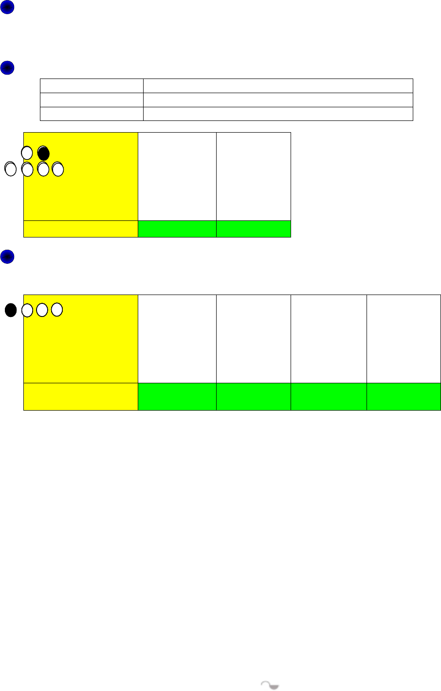
2
One indicates R/W status. One indicates Link status and the others indicate the intensity of
received signals.
R/W:
:
This LED is blinks quickly when the card is flash memory Read or Write.
*
**
*To prevent data loss and/or damage to WLAN Card, never remove WLAN Card from the
USB port while data is transferring.
Link:
Blinking Slow The card is scanning the network.
Continuously On The card is successfully connected to a network.
Blinking Quickly The data is being transmitted/received
LED Light
Condition R/W Link
Intensity of received signals:
This LED specifies the four conditions of “POOR”,
“FAIR”, “GOOD”, and “EXCELLENT” .
LED Light
Condition of the
Receiver POOR FAIR GOOD EXCELLENT
1-5. System Requirements
1-5-1. Supported Platform:
IBM PC/AT compatible computer
1-5-2. Supported Operation System:
Windows 98SE/Me/2000/XP
1-5-3. Software Access Point Supported Operation System:
Windows 2000/XP
1-6. Write-Propect Function
When the Write-Protect switch is set to Unlocked “ ”, you can read/write data

3
from/into Flash Memory. When the Write-Protect switch is set to Locked “ ”, you
can’t write data into Flash Memory or format it. You can only read data from
Flash Memory. Please set the switch to Unlocked “” before format.
4
Chapter 2. Installing the Wireless LAN Card
2-1. Installing The Driver & Utility for PC
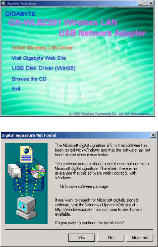
Step 1: Please make sure that you don’t plug your card yet.
Step 2: Execute the setup.exe on our CD, and then the following window will pop up.
Click “Install Wireless LAN Driver”.
Step 3: Click “Yes”.
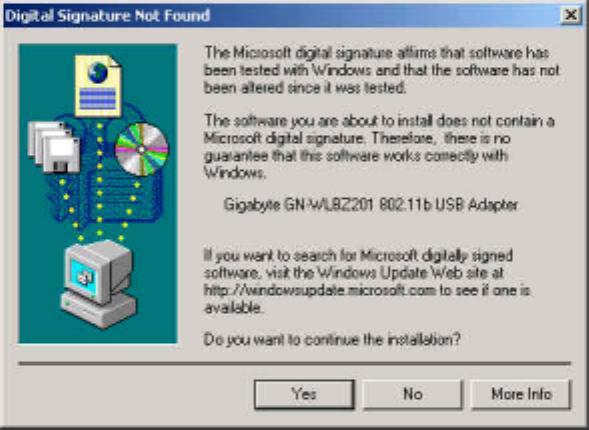
Step 4: Please plug-in your “Gigabyte WLAN card device” ! and will install the device driver
Click “Yes”, and then your installation is ok.
5
6
Chapter 3. Using The Utility on PC
The Configuration & Monitor Utility is a powerful application that helps you to configure the
card and monitor the statistics of the communication link. Unlike the standard method of
configuring the card via the operating system utilities (e.g. Control Panel), this application
permits the dynamic modification of the configuration parameters while the card is
operating. It also offers some more configuration options. It appears as an icon on the
Windows system tray whenever the card is running (see Figure 3-1). The icon can tell you
the received signal strength by four small green lights. You can open it by double-clicking
on this icon.
Figure 3-1. The icon of the Configuration & Monitor Utility
WLAN Mode AP Mode
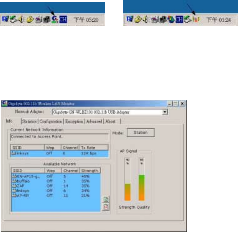
3-1. Info
The Info tab shows you the current Link States of the Wireless LAN Card and the
Reachable Assess Points and the Wireless LAN Card(see Figure 3-2).
Figure 3-2. Current link states of the wireless LAN card
Network Information:There are three states of a Wireless LAN Card:
1. Connected to Access Point: The wireless LAN card is now connecting to an Access
Point.
2. Connected to Ad Hoct: The wireless LAN card is now connecting to a Peer-to-Peer
network.
3. Connecting: The wireless LAN card is now searching for an Access Point or
wireless LAN card with the same network name, or SSID for the connection.
Other items in the table are the detailed information about the link state, which are available
only when the wireless LAN card is connected to an access point or other wireless LAN
card.
7
SSID: Network name.
Channel: The current channel used by the wireless LAN card.
Tx Rate: The current transmission rate used by the wireless LAN card.
AP Signal: It shows the signal quality and signal intensity of the currently connected base
station.
Available Network: This item will show you all of the 802.11 Access Points or Wireless
LAN Cards in your wireless environment. The icon in the front of every item represents
an Access Point or a Wireless LAN Card. You can add a network easily by clicking
on the desired SSID.
Strength: It shows the signal quality and signal intensity of the currently connected base
station.
Signal Quality: It is which represents the quality of communication between the Wireless
LAN Card and Access Point.
Refresh( ): After this button is clicked, the wireless LAN card will rescan the wireless
environment and show you all the updated reachable Access Points and Stations.
Connect( ): After this button is clicked, the wireless LAN card will connect the wireless
environment reachable Access Points or wireless LAN card.
Mode(Station): The WLAN mode You can change AP mode(see 3-7 Access Point) by
clicking on this button.
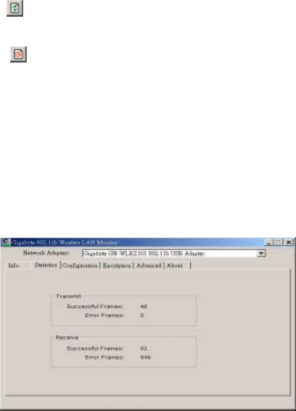
3-2. Statistics
The “Statistics” tab shows you the number of packets sent and received by the card(see
Figure 3-3).
Figure 3-3. The statistic number of packets sent and received by the card
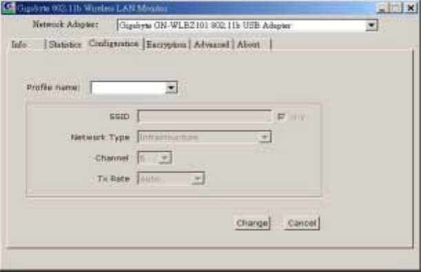
3-3. Configuration
8
The Configuration Tab contains several fields where operating parameters of the driver can
be viewed or changed. Changes to any of the parameters in this panel can be applied to
the driver without resetting the wireless LAN card(see Figure 3-4).
Figure 3-4. Configuration
Profile: You can save various wireless settings for different environments.
Change: Press this button to set the configuration in each field of the panel. The “Apply”
button should be pressed before the default values are saved to the driver and registry.
Cancel: Press this button to restore the default value in each field of the panel.
SSID: It is also known as SSID and is the unique name shared among all access points
(Infrastructure) or Ad Hoc (wireless LAN card) in the wireless network. The SSID
must be identical for all points in the network for sharing information and
communication. It is case sensitive and must not exceed 32 characters
.
Network Type: This field allows you to select the network type from a list of supported
Network “Modes”. The modes displayed have two values:“Ad Hoc”(Peer-to-Peer)and
“Infrastructure”(Access Point).
Ad Hoc: This is the 802.11 peer-to-peer mode of operation. All communications are done
from Client to Client without using the base station. Peer-to-Peer networking uses the
same SSID for establishing the wireless connection.
Infrastructure: This mode of operation requires the presence of an 802.11 Base Station.
All communications are done via the Base Station, which relay packets to other
wireless Clients in the BSS as well as the nodes on a connected network such as
Ethernet.
Channel: This specifies the channel used in wireless communication and should be set to
the same channel as the other points in the wireless network. This setting can only be
adjusted in Ad Hod mode.
TX Rate: The transmission rate for transmitting data packets at the user end. You may set
the transmission rate to 1Mb, 2 Mb, 5.5 Mb, 11 Mb, or Fully Automatic.
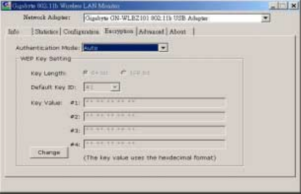
3-4. Encryption
9
To prevent unauthorized user to access the data on wireless stations, the Wireless LAN
Card offers a highly secure data encryption, known as WEP (Wired Equivalent Privacy). If
you require high security in transmission, go to the Encryption tab and set it up as
follows(see Figure 3-5).
Figure 3-5. Encryption
Change: Press this button to set the configuration in each field of the panel. The “Apply”
button should be pressed before the default values are saved to the driver and registry.
Key Length: select either 64bit or 128bit encryption method.
64 Bit –Allows wireless LAN card to encrypt data with the 64-Bit encryption algorithm.
128 Bit –Allows wireless LAN card to encrypt data with the 28-Bit encryption algorithm.
The Encryption tab enables you to identify up to 4 different encryption passwords and
select one of them to encrypt your transmission data. The password of your choice may
either be:
For 64-bit encryption:
! Five alphanumeric characters in the range of “a-z”, “A-Z” and “0-9” (e.g. MyKey)
! 10 hexadecimal values in the range of “0-F” (e.g. 11AA22BB33).
For 128-bit encryption:
! 13 alphanumeric characters in the range of “a-z”, “A-Z” and “0-9” (e.g. WEPencryption).
! 26 hexadecimal values in the range of “0-F” (e.g. 11AA22BB33123456789ABCDEFF).
you have the option to select whether Open System, Shared Key, or Auto authentication
will be used. In order to take effect the changes you wish to make, click the “Apply” button
at the bottom of the screen.
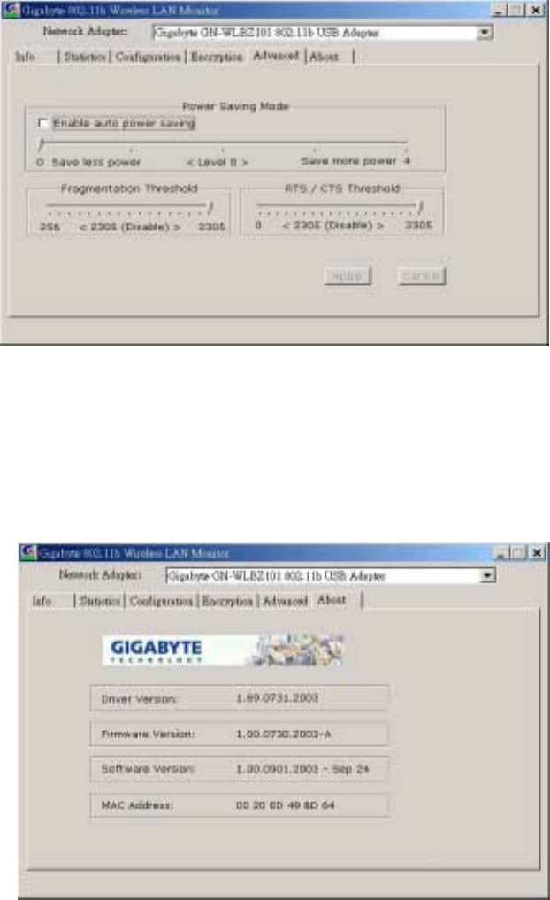
3-5. Advanced
By Choosing the Advanced option in any of the two modes, you can change advanced
configuration settings, such as the Fragmentation Threshold, and RTS/CTS Threshold (see
Figure 3-6). Figure 3-6 shows the default configuration for the advanced settings.
Note: In order to enable the Fragmentation and the RTS/CTS Threshold parameters move
the slide bar with your mouse and then use the right and left arrow keys of your keyboard in
10
order to select an exact number.
Figure 3-6. Advanced settings
3-6. About
By choosing this option, you can view basic information about the utility like the Driver,
Firmware and Application Version and this adapter’s MAC address(see Figure 3-7).
Figure 3-7. Version information and MAC address
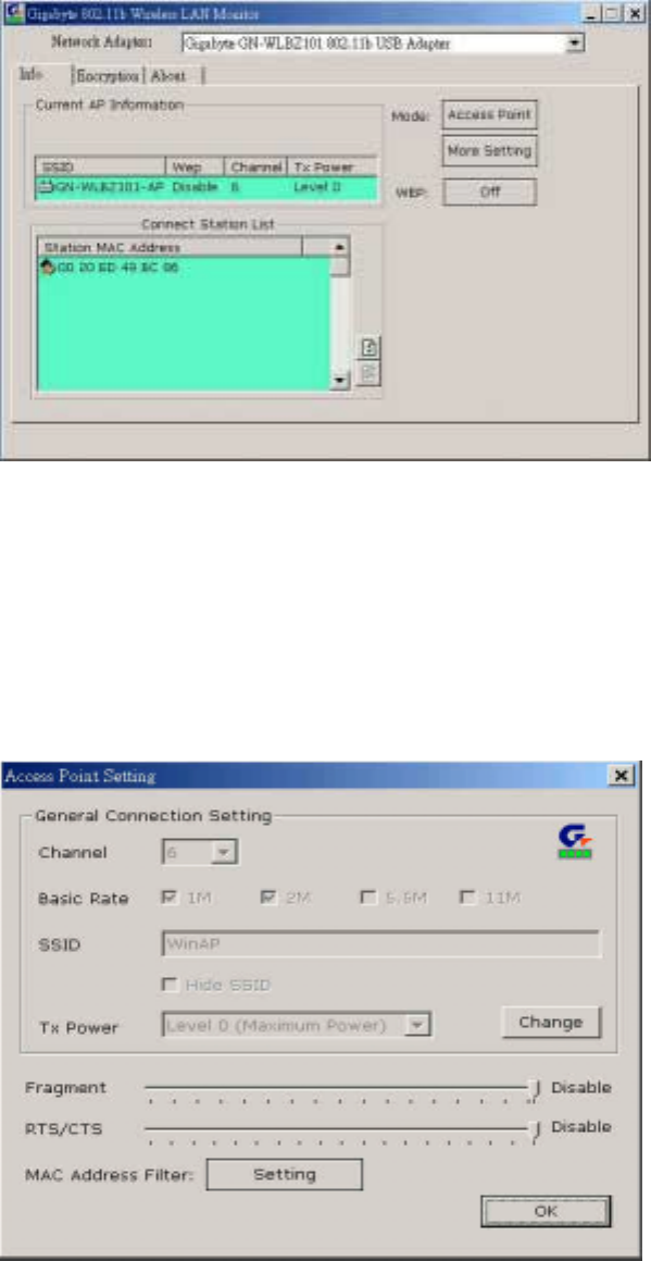
3-7. Access Point
(Supported under Windows XP)
The Info tab shows you the current Link States of the Assess Points and the Wireless LAN
Card (see Figure 3-8).
11
Figure 3-8. Current link states of the Access Point Mode
Access Point: The AP mode You can change WLAN mode(see 3-1 Info) by clicking on
this button.
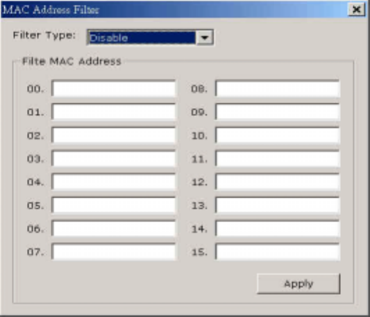
More Setting: You can set the configuration Access Point(see Figure 3-9) by clicking on
this button.
WEP(ON/OFF): You can using WEP (Wired Equivalent Privacy) by clicking on this button.
Figure 3-9. configuration of the Access Point Mode
Change: Press this button to setting the default value in each field of the panel. The “Apply”
button should be pressed before the default values are saved to the driver and registry.
Channel: The current channel used by the Access Point.
Basic Rate: The transmission rate for transmitting data packets at the user end. You may
set the transmission rate to 1Mb, 2 Mb, 5.5 Mb, 11 Mb.
SSID: Network name.
12
Hide SSID: Access Point disable their SSID broadcasting to prevent a wireless device from
finding and accessing their networks.
Tx Power: Transmitter Output power.
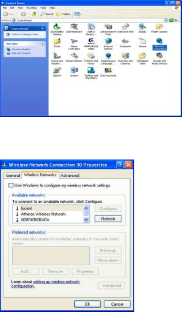
MAC Address Filter: You can set the configuration MAC Address Filter(see Figure 3-10)
by clicking on this button.
Figure 3-10. MAC Address Filter
Filter Type: There are three status of a Access Point:
1. Disable: The Filter MAC Address function disable.
2. Accept: The Filter MAC Address (wireless LAN card) can connect to a Access
Point.
3. Reject: The Filter MAC Address (wireless LAN card) can’t connect to a Access
Point.
3-8. Bridge Setup
(Supported under Windows XP)
Step 1: Change to AP mode (see Figure 3-8).
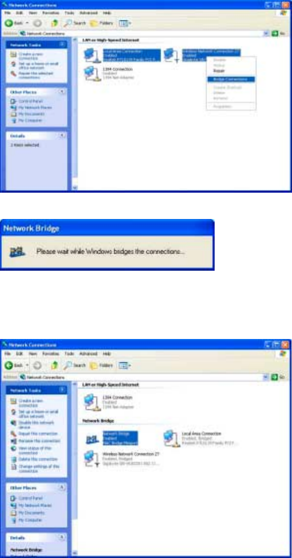
Step 2: 「Control Panel」run「Network Connections」 (see Figure 3-11).
13
Figure 3-11. Control Panel
Step 3: Setup Wireless LAN card(see Figure 3-12), Click ”Use Windows to configure” to
cancel the schedule and Click「OK」.
Figure 3-12. Wireless Networks
Step 4:
::
: Select the network connections to be bridged. Press the 「
「「
「Ctrl」
」」
」 key while clicking
the network connection icons to select. Right-click on any selected network icon.
Select 「
「「
「Bridge Connections」
」」
」(see Figure 3-13).
Show Network Bridge(see Figure 3-14).
14
Figure 3-13. Bridge Connections
Figure 3-14. Network Bridge
Step 5:
::
: Setup OK,Show Network Bridge windows(see Figure 3-15) and then your setup
is ok.
Figure 3-15. Network Bridge Enabled
3-9. IP Sharing
(Supported under Windows 2000)
Step 1: Change to AP mode (see Figure 3-8).
Step 2: 「Control Panel」run「Network and Dial-up Connections」 (see Figure 3-16).
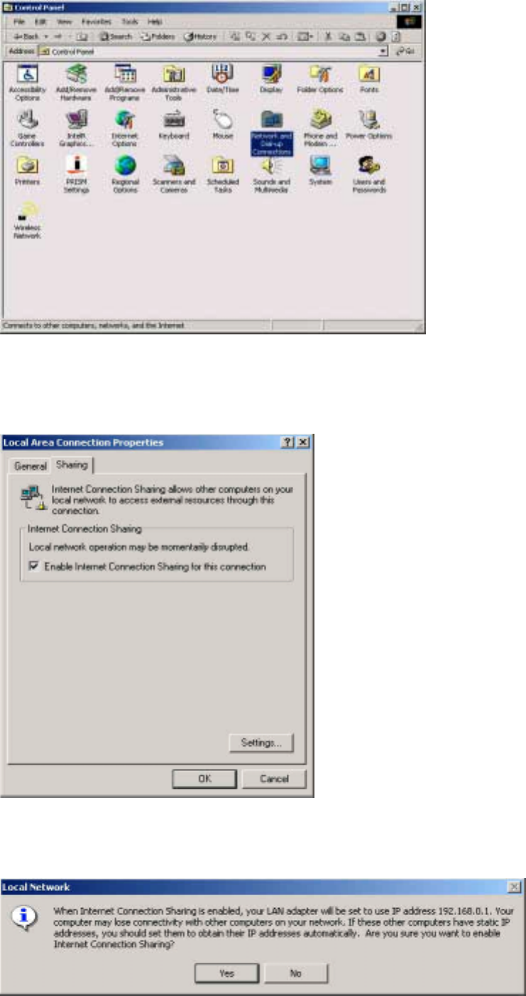
15
Figure 3-16. Control Panel
Step 3: Setup LAN card(see Figure 3-17), Click ”Enable Internet Connection Sharing for
this connection” and Click「OK」.
Figure 3-17. Local Area Connection Properties
Step 4:
::
: Show Local Network(see Figure 3-18). Click「
「「
「OK」
」」
」 and then your setup is ok.
Figure 3-18. Local Network

16
Chapter 4. Specification
System
Flash Memory 32Mbytes /64Mbytes /128Mbytes
Standards IEEE 802.11b compliant
Host Interface USB1.1
Modulation 1Mbps: DBPSK; 2Mbps: DQPSK; 5.5 and 11 Mbps: CCK
Data Rate 1, 2, 5.5, 11 Mbps
Operating Voltage 5V
Power Tx 340mA; Rx 300 mA; Sleep 90 mA
Operating Range Outdoor: 100 - 300m; Indoor: 30 - 100m
RF
Frequency Band 2.400 ~ 2.484 GHz (subject to local regulation)
Radio Technology DSSS (Direct Sequence Spread Spectrum)
11 Channels (US, Canada) 4 channels (France)
Number of Channel 14 Channels (Japan) 13 Channels (Most European countries, ETSI)
Peak Output power 16dBm@ Nominal Temp Range
Receive Sensitivity - 80dBm @ 11 Mbps date rate, 8% PER
Antenna one built-in Chip antenna
Regulatory and Environmental Compliance
FCC part 15 (USA) DGT (Taiwan)
EMC certification CE (Europe) TELEC (Japan)
Temperature Range Operating: 0 ~ 50 degree C, Storage: -20 ~ 65 degree C
Humidity Max. 90% Non-condensing
Software
Driver Windows 98SE/ME/2000/XP
Roaming Full mobility and seamless roaming
AP Function Supported under Windows 2000/XP
Security 64 and 128 bit WEP
Management Utility Monitors the network situation.
Mechanical
Dimensions 126mm * 25mm * 16mm
Weight 27 ± 1 g
Packaging Generic, Gigabyte, private labeling optional
LED indicators Read/Write ,Link and intensity of received signals
Note: The specifications are subject to change without notice
GIGABYTE declares that GN-WLBZ201 (IEEE 802.11b USB STICK Storage /
Wireless LAN Card ) ( FCC ID: JCK-GN-WLBZ201 ) is limited in CH1~CH11
by specified firmware controlled in USA.