GIGA TMS MINI400B Portable MSR Reader with Bluetooth User Manual Visio MINI400B User s Manual vsd
GIGA-TMS INC. Portable MSR Reader with Bluetooth Visio MINI400B User s Manual vsd
UserManual.wiki
>
GIGA TMS
>
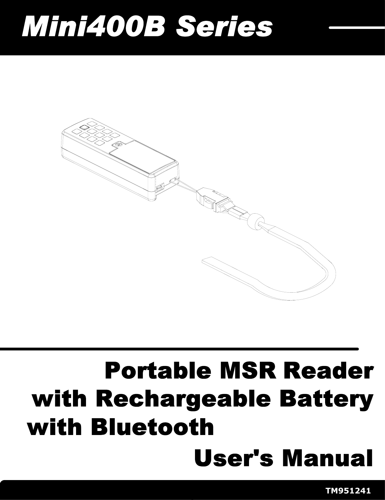
MINI400B User Manual
Users Manual
Navigation menu
Upload a User Manual
Namespaces
Wiki Guide
HTML
PDF
Info
Views
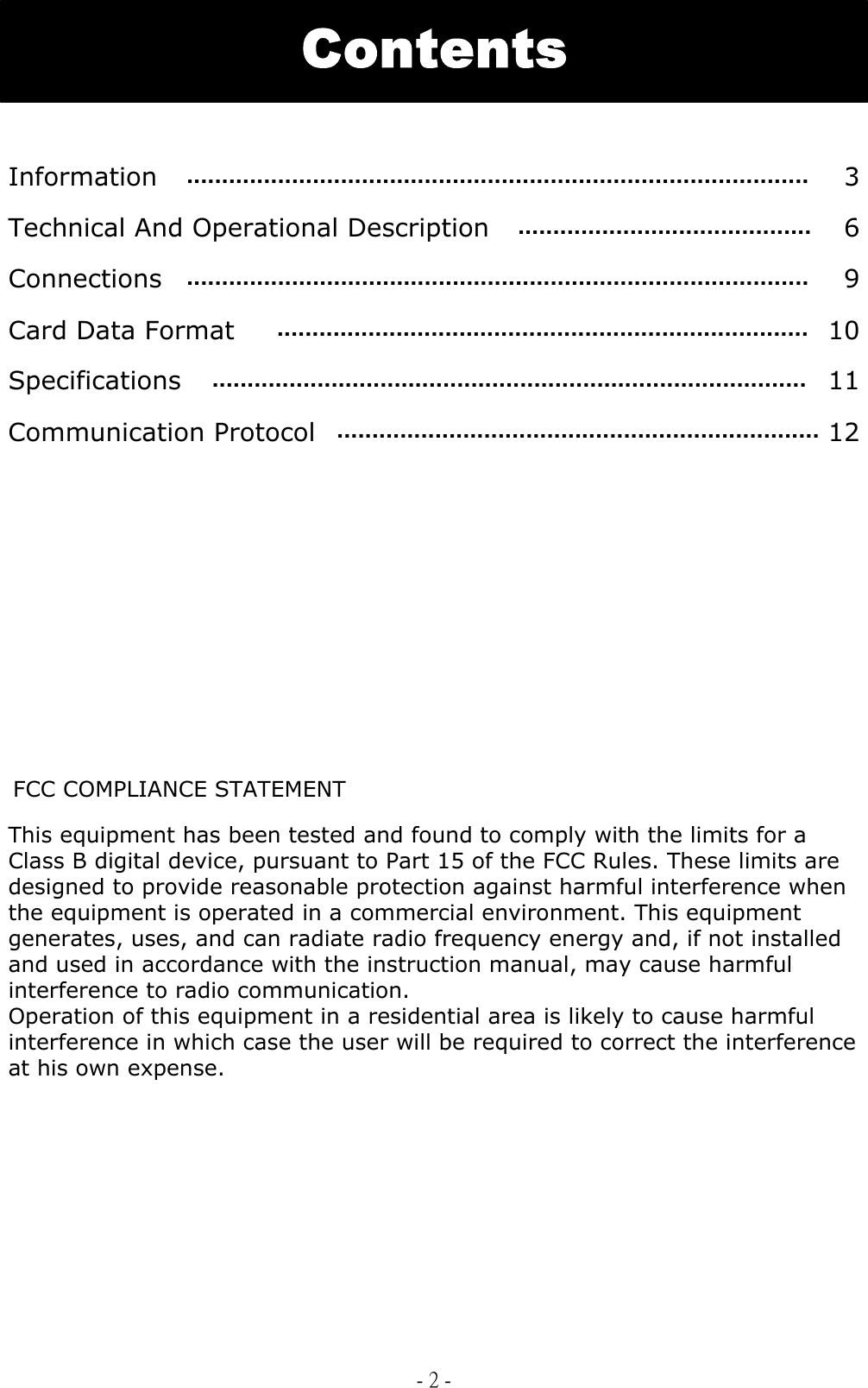
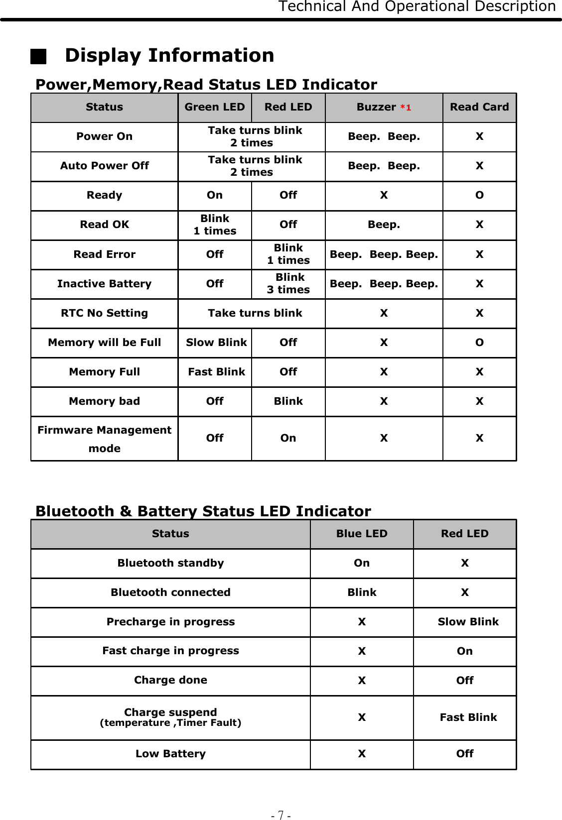
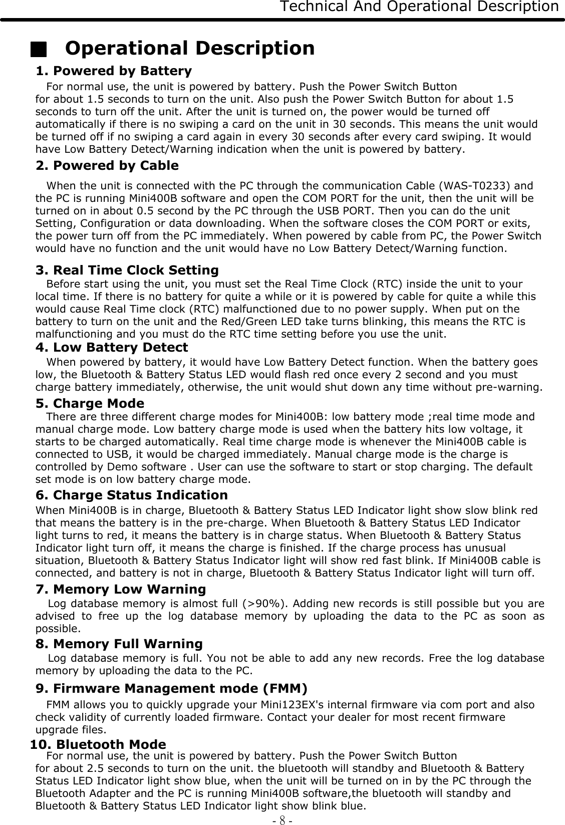
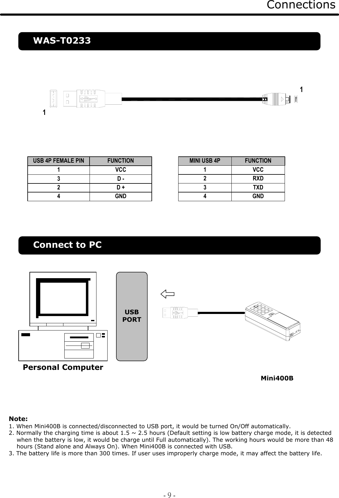
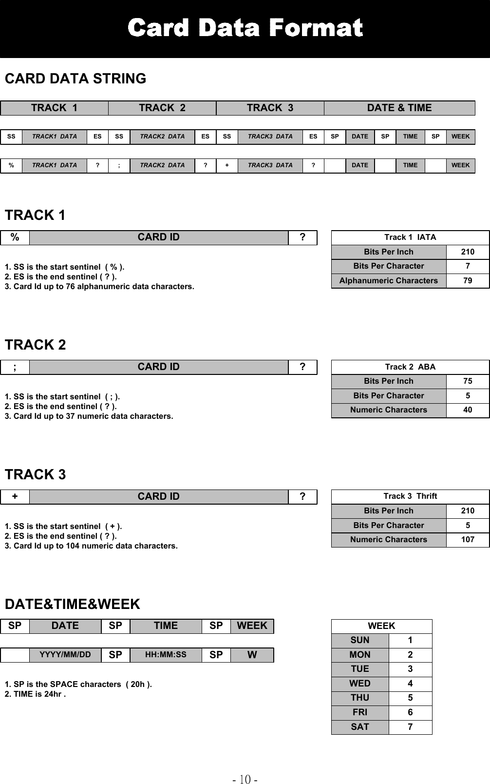
User Manual
Discussion / Help
Navigation